JP5351945B2 - Power monitoring and control device and control device for distributed power supply system - Google Patents
Power monitoring and control device and control device for distributed power supply system Download PDFInfo
- Publication number
- JP5351945B2 JP5351945B2 JP2011205144A JP2011205144A JP5351945B2 JP 5351945 B2 JP5351945 B2 JP 5351945B2 JP 2011205144 A JP2011205144 A JP 2011205144A JP 2011205144 A JP2011205144 A JP 2011205144A JP 5351945 B2 JP5351945 B2 JP 5351945B2
- Authority
- JP
- Japan
- Prior art keywords
- power supply
- power
- predetermined
- permission signal
- control device
- Prior art date
- Legal status (The legal status is an assumption and is not a legal conclusion. Google has not performed a legal analysis and makes no representation as to the accuracy of the status listed.)
- Expired - Fee Related
Links
- 238000012544 monitoring process Methods 0.000 title claims description 76
- 230000005540 biological transmission Effects 0.000 claims description 28
- 238000000034 method Methods 0.000 claims description 14
- 230000008054 signal transmission Effects 0.000 claims description 14
- 230000002265 prevention Effects 0.000 claims description 4
- 238000004891 communication Methods 0.000 description 21
- 238000001514 detection method Methods 0.000 description 15
- 238000010248 power generation Methods 0.000 description 8
- 238000005259 measurement Methods 0.000 description 7
- 238000010586 diagram Methods 0.000 description 4
- 230000000694 effects Effects 0.000 description 4
- 238000004590 computer program Methods 0.000 description 3
- 230000001360 synchronised effect Effects 0.000 description 3
- 230000005856 abnormality Effects 0.000 description 2
- 230000000903 blocking effect Effects 0.000 description 2
- 239000000446 fuel Substances 0.000 description 2
- 238000012545 processing Methods 0.000 description 2
- 238000007792 addition Methods 0.000 description 1
- 238000013459 approach Methods 0.000 description 1
- 238000006243 chemical reaction Methods 0.000 description 1
- 238000005516 engineering process Methods 0.000 description 1
- 230000010365 information processing Effects 0.000 description 1
- 238000012986 modification Methods 0.000 description 1
- 230000004048 modification Effects 0.000 description 1
- 238000000926 separation method Methods 0.000 description 1
- 238000011144 upstream manufacturing Methods 0.000 description 1
Images


Classifications
-
- H—ELECTRICITY
- H02—GENERATION; CONVERSION OR DISTRIBUTION OF ELECTRIC POWER
- H02J—CIRCUIT ARRANGEMENTS OR SYSTEMS FOR SUPPLYING OR DISTRIBUTING ELECTRIC POWER; SYSTEMS FOR STORING ELECTRIC ENERGY
- H02J13/00—Circuit arrangements for providing remote indication of network conditions, e.g. an instantaneous record of the open or closed condition of each circuitbreaker in the network; Circuit arrangements for providing remote control of switching means in a power distribution network, e.g. switching in and out of current consumers by using a pulse code signal carried by the network
- H02J13/00032—Systems characterised by the controlled or operated power network elements or equipment, the power network elements or equipment not otherwise provided for
- H02J13/00034—Systems characterised by the controlled or operated power network elements or equipment, the power network elements or equipment not otherwise provided for the elements or equipment being or involving an electric power substation
-
- H—ELECTRICITY
- H02—GENERATION; CONVERSION OR DISTRIBUTION OF ELECTRIC POWER
- H02J—CIRCUIT ARRANGEMENTS OR SYSTEMS FOR SUPPLYING OR DISTRIBUTING ELECTRIC POWER; SYSTEMS FOR STORING ELECTRIC ENERGY
- H02J13/00—Circuit arrangements for providing remote indication of network conditions, e.g. an instantaneous record of the open or closed condition of each circuitbreaker in the network; Circuit arrangements for providing remote control of switching means in a power distribution network, e.g. switching in and out of current consumers by using a pulse code signal carried by the network
- H02J13/00002—Circuit arrangements for providing remote indication of network conditions, e.g. an instantaneous record of the open or closed condition of each circuitbreaker in the network; Circuit arrangements for providing remote control of switching means in a power distribution network, e.g. switching in and out of current consumers by using a pulse code signal carried by the network characterised by monitoring
-
- H—ELECTRICITY
- H02—GENERATION; CONVERSION OR DISTRIBUTION OF ELECTRIC POWER
- H02J—CIRCUIT ARRANGEMENTS OR SYSTEMS FOR SUPPLYING OR DISTRIBUTING ELECTRIC POWER; SYSTEMS FOR STORING ELECTRIC ENERGY
- H02J3/00—Circuit arrangements for ac mains or ac distribution networks
- H02J3/001—Methods to deal with contingencies, e.g. abnormalities, faults or failures
- H02J3/0012—Contingency detection
-
- H—ELECTRICITY
- H02—GENERATION; CONVERSION OR DISTRIBUTION OF ELECTRIC POWER
- H02J—CIRCUIT ARRANGEMENTS OR SYSTEMS FOR SUPPLYING OR DISTRIBUTING ELECTRIC POWER; SYSTEMS FOR STORING ELECTRIC ENERGY
- H02J2310/00—The network for supplying or distributing electric power characterised by its spatial reach or by the load
- H02J2310/10—The network having a local or delimited stationary reach
-
- H—ELECTRICITY
- H02—GENERATION; CONVERSION OR DISTRIBUTION OF ELECTRIC POWER
- H02J—CIRCUIT ARRANGEMENTS OR SYSTEMS FOR SUPPLYING OR DISTRIBUTING ELECTRIC POWER; SYSTEMS FOR STORING ELECTRIC ENERGY
- H02J3/00—Circuit arrangements for ac mains or ac distribution networks
Landscapes
- Engineering & Computer Science (AREA)
- Power Engineering (AREA)
- Remote Monitoring And Control Of Power-Distribution Networks (AREA)
- Supply And Distribution Of Alternating Current (AREA)
Description
本発明は、電力監視制御装置及び分散型電源システムの制御装置に関する。 The present invention relates to a power monitoring control device and a control device for a distributed power supply system.
電力会社等の電力供給者から各需要家(個人住宅、ビルディング、工場等)に商用電源を供給するための経路及び電気設備を、電力系統と呼ぶ。通常の場合、一部の大規模需要家を除いて、各需要家は、電力系統からの商用電源のみを使用していた。 A path and electrical equipment for supplying commercial power from a power supplier such as an electric power company to each consumer (personal house, building, factory, etc.) are called a power system. In normal cases, except for some large-scale customers, each customer used only commercial power from the power grid.
しかし、近年は、太陽光発電、風力発電、ヒートポンプ、燃料電池等の、自然環境への負荷が少ないエネルギ源の普及が望まれている。それらの電源は各需要家毎に設けられるため、都市から離れた場所に集中して設けられる従来の大規模発電所に対して、分散型電源と呼ばれる。 However, in recent years, it has been desired to spread energy sources such as solar power generation, wind power generation, heat pumps, fuel cells, and the like that have a low load on the natural environment. Since these power sources are provided for each consumer, they are called distributed power sources for a conventional large-scale power plant that is concentrated in a place away from the city.
電力系統に障害が発生した場合、作業員の安全を確保すべく、電力系統に接続された分散型電源を全て一律に停止させる必要がある。そこで、分散型電源には、単独運転を防止するための装置が予め設けられている(特許文献1,2)。
When a failure occurs in the power system, all distributed power sources connected to the power system must be uniformly stopped to ensure the safety of workers. Therefore, a device for preventing isolated operation is provided in advance in the distributed power supply (
電力系統の故障に伴って、電力系統から分離された系統区間が生じる。近年では、分散型電源が普及しているため、系統区間での発電量と消費量とがバランスしない場合があると考えられる。そこで、分散型電源に設けられている単独運転防止装置を正常に動作させるための技術(特許文献1)、および、分散型電源が単独で運転していることを警告するための技術(特許文献2)が提案されている。 With the failure of the power system, a system section separated from the power system occurs. In recent years, since distributed power sources have become widespread, it is considered that the amount of power generated and the amount of consumption in the system section may not be balanced. Therefore, a technique for operating the isolated operation prevention device provided in the distributed power supply normally (Patent Document 1) and a technique for warning that the distributed power supply is operating independently (Patent Document 1) 2) has been proposed.
このように、従来技術では、電力系統の故障時に分散型電源の単独運転を防止することを前提にしているため、大規模な自然災害が発生した場合に、停電発生地域に分散している分散型電源を有効に活用できない。 In this way, the conventional technology is based on the premise of preventing isolated operation of a distributed power source in the event of a power system failure. Type power supply cannot be used effectively.
そこで、本発明の目的は、分散型電源システムを有効に活用することができるようにした電力監視制御装置及び分散型電源システムの制御装置を提供することにある。本発明の他の目的は、電力系統に障害が発生した場合に、安全を確保しつつ、分散型電源システムを有効に活用することができるようにした電力監視制御装置及び分散型電源システムの制御装置を提供することにある。 SUMMARY OF THE INVENTION An object of the present invention is to provide a power monitoring control device and a control device for a distributed power supply system that can effectively use a distributed power supply system. Another object of the present invention is to provide a power monitoring control device and a control of the distributed power supply system that can effectively use the distributed power supply system while ensuring safety when a failure occurs in the power system To provide an apparatus.
上記課題を解決すべく、本発明に係る電力監視制御装置は、電力系統を監視して制御する電力監視制御装置であって、所定の開閉器を操作することで電力系統から分離される所定の系統区間について、所定の系統区間に含まれる分散型電源システムによる所定の系統区間への電力供給を許可するための許可信号を、分散型電源システムに送信するか否かを判定するための独立運転判定部と、許可信号を分散型電源システムに送信するための許可信号送信部と、を備え、独立運転判定部は、電力系統から所定の系統区間への電力供給の停止を検出した場合に、許可信号を許可信号送信部から分散型電源システムに送信させるようになっている。 In order to solve the above-described problems, a power monitoring control device according to the present invention is a power monitoring control device that monitors and controls a power system, and is a predetermined power source that is separated from the power system by operating a predetermined switch. Independent operation for determining whether or not to transmit a permission signal for permitting power supply to a predetermined system section by the distributed power system included in the predetermined system section to the distributed power system. A determination unit and a permission signal transmission unit for transmitting a permission signal to the distributed power supply system, and the independent operation determination unit detects a stop of power supply from the power system to a predetermined system section, The permission signal is transmitted from the permission signal transmission unit to the distributed power supply system.
許可信号は、所定の開閉器を操作して所定の系統区間を生成するための操作信号を兼ねてもよい。 The permission signal may also serve as an operation signal for operating a predetermined switch to generate a predetermined system section.
許可信号の送信の可否を決定するための可否決定情報を独立運転判定部に設定するための設定部をさらに備えることもできる。
本発明の構成の少なくとも一部は、コンピュータプログラムとして実現できる。コンピュータプログラムは、例えば、インターネットのような通信媒体、ハードディスクまたはフラッシュメモリデバイスのような記録媒体を介して、配布することができる。
A setting unit for setting permission determination information for determining permission of transmission of the permission signal in the independent operation determination unit may be further provided.
At least a part of the configuration of the present invention can be realized as a computer program. The computer program can be distributed, for example, via a communication medium such as the Internet, a recording medium such as a hard disk or a flash memory device.
以下、図面に基づいて、本発明の実施の形態を説明する。本実施形態では、以下に詳述するように、電力監視制御装置1は、電力系統から分離される所定の系統区間について、分散型電源システム3の単独運転を許可するための許可信号を、分散型電源システムに送信する。どの分散型電源システムの運転を許可するかは、事前に管理者が設定したり、または、遠隔操作で指示したりできる。
Hereinafter, embodiments of the present invention will be described with reference to the drawings. In the present embodiment, as will be described in detail below, the power monitoring and
これにより、本実施形態では、地震等により電力系統に障害が発生した場合に、系統区間に設けられた分散型電源システムを独立運転させて、系統区間に電力を供給することができる。従って、電力系統の故障時において、系統区間に存在する電気的負荷(需要家)に電力を供給することができ、利便性を高めることができる。 Thereby, in this embodiment, when a failure occurs in the power system due to an earthquake or the like, it is possible to independently operate the distributed power supply system provided in the system section and supply power to the system section. Therefore, at the time of failure of the power system, power can be supplied to the electrical load (customer) existing in the system section, and convenience can be improved.
図1は、「電力監視制御装置」としての独立運転監視制御装置1を含む配電システムの全体構成図である。配電システムは、例えば、独立運転監視制御装置1(以下、監視制御装置1)と、配電変電所2と、分散型電源システム3と、一般負荷4と、重要負荷5と、を備えることができる。なお、配電システムの構成は、各国毎に相違する。図1に示す構成はその一例であって、本発明は図1に示す構成以外の配電システムにも適用することができる。
FIG. 1 is an overall configuration diagram of a power distribution system including an independent operation
配電変電所2は、送電所から基幹送電網6を介して供給される電力の電圧値を低下させ、各需要家4,5に所定電圧の電力を供給する。配電変電所5は、複数の配線フィーダ(電力供給線)7を介して、各需要家4,5に電力を供給する。
The
ここで、需要家は、例えば、一般需要家(一般負荷)4と、重要な需要家(重要負荷)5とに大別することができる。図中では、需要家を電気的負荷として表現している。以下の説明では、一般需要家を一般負荷と、重要な需要家を重要負荷と呼ぶ。一般負荷4としては、例えば、通常の個人住宅、オフィスビルディング、商業施設等がある。重要負荷5としては、例えば、病院、役所、警察署、消防署等のような、災害発生時に電力供給を維持すべき場所の負荷を挙げることができる。
Here, consumers can be roughly classified into, for example, general consumers (general loads) 4 and important consumers (important loads) 5. In the figure, consumers are expressed as electrical loads. In the following description, general consumers are referred to as general loads, and important consumers are referred to as important loads. Examples of the
監視制御装置1は、コンピュータシステムとして構成されており、例えば、マイクロプロセッサが所定のコンピュータプログラムを実行することで、所定の機能を実現するようになっている。監視制御装置1は、第1の通信網CN1を介して、分散型電源システム3に接続されている。さらに、監視制御装置1は、第2の通信網CN2を介して、管理装置8と接続されている。第1の通信網CN1と第2の通信網CN2とは、共通の通信網として構成してもよいし、それぞれ異なる通信網として構成してもよい。
The
監視制御装置1は、その機能として、例えば、独立運転判定部10と、計測値入力部11と、設定入力部12と、遠隔指令受信部13と、開閉器制御信号出力部14と、独立運転許可信号送信部15とを備える。
The
独立運転判定部10は、電力系統から分離された所定の系統区間としての配電フィーダ7を独立運転させるべきか否かを判定する。独立運転とは、電力系統から切り離された配電フィーダ7に接続されている分散型電源システム3の単独運転を意味し、分散型電源システム3から配電フィーダ7への電力供給を許す運転状態である。
The independent
計測値入力部11は、配電変電所2に供給される電力の状態を監視する。独立運転判定部10は、計測値入力部11により検出される電力供給状態に基づいて、配電変電所2への電力供給が絶たれたか否かを監視する。
The measured
基幹送電網6から配電変電所2への電力供給が停止すると、独立運転判定部10は、設定入力部12または遠隔指令受信部13のいずれかから入力される可否決定情報に基づいて、分散型電源システム3の単独運転を許可するかを判定する。
When power supply from the
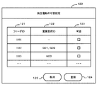
可否決定情報とは、電力系統から分離された配電フィーダ7に接続されている分散型電源システム3の単独運転を許可するか否かを予め設定している情報である。「設定部」としての設定入力部12は、図5に示すような設定画面120を生成して出力することができる。
The availability determination information is information that sets in advance whether or not to permit independent operation of the distributed
先に図5を参照して、設定画面120の構成を説明する。設定画面120は、例えば、配電フィーダ識別子欄121と、重要負荷識別子欄122と、可否フラグ欄123とを備える。配電フィーダ識別子欄121は、各配電フィーダ7を識別するためのフィーダ識別子を記憶する。なお図中では、識別子をIDと表記する。重要負荷識別子欄122は、配電フィーダ識別子欄121で特定される配電フィーダ7に接続されている、重要負荷5を識別するための重要負荷識別子を記憶する。可否フラグ欄123は、配電フィーダ識別子欄121で特定される配電フィーダ7が電力系統から分離された場合に、独立運転(分散型電源システム3の単独運転)を許可するか否かを示す制御フラグを記憶する。
First, the configuration of the
監視制御装置1を管理する管理者は、画面120を用いて、各配電フィーダ7毎に独立運転の可否を設定する。管理者が登録ボタン124を操作すると、設定画面120に設定された内容が登録される。
An administrator who manages the
「設定部」としての遠隔指令受信部13は、外部の管理装置8から可否決定情報を受信する。管理装置8は、例えば、電力集中監視制御システムの一部として構成することができる。または、管理装置8は、管理者の保持するパーソナルコンピュータあるいは情報処理端末(携帯電話を含む)として構成してもよい。本実施例では、可否決定情報を設定するための設定部として、設定入力部12と遠隔指令受信部13の両方を例示するが、いずれか一方のみを備える構成でもよい。
The remote
開閉器制御信号出力部14は、電力系統と配電フィーダ7との間に設けられる開閉器22(図3参照)の動作を制御するための制御信号を出力する。開閉器制御信号出力部14は、例えば、「電力系統と所定の系統区間とを接続するための開閉部を操作するための信号を出力する開閉操作部」と表現してもよい。
The switch control
開閉器制御信号出力部14から開閉器22に開信号が送信されると、開閉器22は開状態となり、開閉器22に接続された配電フィーダ7は電力系統(基幹送電網6)から分離される。これに対し、開閉器制御信号出力部14から開閉器22に閉信号が送信されると、開閉器22は閉状態となり、開閉器22に接続された配電フィーダ7は電力系統に再接続される。
When an open signal is transmitted from the switch control
「許可信号送信部」としての独立運転許可信号送信部15は、独立運転の許可された配電フィーダ7に接続されている分散型電源システム3に対して、独立運転(単独運転)を許可するための信号を送信する。以下、独立運転許可信号を「許可信号」と略記する場合がある。
The independent operation permission
上述の通り、独立運転判定部10は、基幹送電網6から配電変電所2への電力供給が停止すると、電力系統から切り離された配電フィーダ7について独立運転を許可するフラグが設定されているかを判定する。許可フラグが設定されている場合、独立運転判定部10は、開閉器制御信号出力部14から開信号を出力させ、その配電フィーダ7を電力系統から分離する。続いて、独立運転判定部10は、独立運転許可信号送信部15から、分離された配電フィーダ7に接続された分散型電源システム3に対して、独立運転を許可するための許可信号を送信する。
As described above, when the power supply from the main
分散型電源システム3の構成は、図4で後述するものとし、先に図2を参照する。図2は、配電系統の構成を模式的に示す。図2では、配電変電所2内に監視制御装置1を設けている。なお、監視制御装置1を配電変電所2の外部に設ける構成でもよい。
The configuration of the distributed
配電変電所2は、基幹送電網6から供給される電力の電圧値を、変圧器21で所定の電圧値に変換し、母線20に出力する。配電用の母線20には、複数の配電フィーダ7(1)、7(2)が開閉器22(1)、22(2)を介して接続されている。一方の配電フィーダ7(1)には、一方の開閉器22(1)を介して、配電変電所2から電力が供給されている。他方の配電フィーダ7(2)には、他方の開閉器22(2)を介して、配電変電所2から電力が供給されている。
The
一方の配電フィーダ7(1)には、複数の一般負荷4と、一つの分散型電源システム3とが接続されている。他方の配電フィーダ7(2)には、一般負荷4及び重要負荷5と、複数の分散型電源システム3とが接続されている。
A plurality of
一方の配電フィーダ7(1)では、分散型電源システム3が少なく、かつ、災害発生時の電力供給を必要とする重要負荷5を有さない。従って、管理者は、一方の配電フィーダ7(1)について、独立運転を許可しないようにフラグを設定してもよい。
On the other hand, the distribution feeder 7 (1) has few distributed
これに対し、他方の配電フィーダ7(2)では、災害発生時にも電力を供給すべき重要負荷5を備えており、かつ、複数の多い分散型電源システム3を有している。従って、管理者は、他方の配電フィーダ7(2)について、独立運転を許可するようにフラグを設定してもよい。
On the other hand, the other distribution feeder 7 (2) includes an
このように、管理者は、例えば、配電フィーダ7に含まれる重要負荷5の種類及び数と、配電フィーダ7に含まれる分散型電源システム3の数及び合計発電能力とに基づいて、災害発生時に独立運転を許可する配電フィーダ7を事前に決定できる。
In this way, the administrator can, for example, at the time of disaster occurrence based on the type and number of
図3は、配電変電所2の機能構成を示す。配電変電所2には、上述のように、監視制御装置1を設置することができる。配電変電所2は、例えば、母線20と基幹送電網6との間に設けられる変圧器21と、母線20と配電フィーダ7との間に設けられる開閉器22と、計測値入力部11に接続される電圧計測部24と、開閉器制御信号出力部14に接続される開閉器操作部25とを備える。
FIG. 3 shows a functional configuration of the
無停電電源23は、基幹送電網6から配電変電所2への電力供給が停止した場合に、監視制御装置1に電力を供給する。電圧計測部24は、母線20の電圧値を計測する。計測された電圧値は、電圧計測部24から計測値入力部11に入力される。開閉器操作部25は、開閉器制御信号出力部14からの制御信号に従って、開閉器22を開閉するための信号を出力する。
The
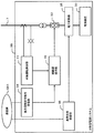
図4は、分散型電源システム3の機能構成を示す。分散型電源システム3は、例えば、電源装置30と、単独運転検出部31と、開閉器操作部32と、開閉器33と、独立運転許可信号受信部34と、電力変換器35とを備える。単独運転検出部31と、開閉器操作部32と、独立運転許可信号受信部34とは、それぞれ電子回路として構成することができる。分散型電源システム3の制御装置は、例えば、単独運転検出部31と、開閉器操作部32と、独立運転許可信号受信部34とから構成することができる。
FIG. 4 shows a functional configuration of the distributed
電源装置30は、例えば、太陽光発電装置、太陽熱発電装置、風力発電装置、燃料電池コジェネレータ等のように構成される。電源装置30により発電される電力は、電力変換器35を介して、配電フィーダ7に供給される。電力変換器35は、直流と交流とを変換したり、周波数を調整したり、電圧値を調整したりする電気回路である。
The
単独運転検出部31は、単独運転状態を防止するための機能である。単独運転検出部31は、配電フィーダ7の電圧値を監視し、配電フィーダ7からの電力供給が途絶えた場合に、開閉器操作部32に対して、開信号を出力するように指示する。
The isolated
開閉器操作部32は、配電フィーダ7と電力変換器35との間に設けられる開閉器33の開閉を操作するための機能である。開閉器操作部32は、単独運転検出部31から開信号の出力を指示されると、開信号を開閉器33に出力し、配電フィーダ7と電力変換器35との間を遮断する。これにより、電源装置30により発電される電力が配電フィーダ7に流れ込むのを防止する。
The
独立運転許可信号受信部34は、監視制御装置1の独立運転許可信号送信部15から第1の通信網CN1を介して、独立運転を許可する信号を受信する。独立運転許可信号受信部34は、開閉器操作部32に許可信号を送信し、開閉器操作部32が開閉器33に開信号を出力するのを抑止する。以下、独立運転許可信号送信部15を許可信号送信部15と呼び、独立運転許可信号受信部34を許可信号受信部34と呼ぶことがある。
The independent operation permission
許可信号受信部34は、監視制御装置1の許可信号送信部15から許可信号を受信できない場合、許可信号を開閉器操作部32に送信しない。このため、単独運転検出部31から開閉器操作部32に送信される、開信号の出力指示を有効になる。この結果、開閉器操作部32は、開閉器33に開信号を出力し、電力変換器35と配電フィーダ7との間を電気的に遮断する。以下の説明では、開閉器33に開信号を出力させる指示を遮断指示と呼ぶことがある。
The permission
このように、開閉器操作部32は、単独運転検出部31からの遮断指示を受領している場合でも、許可信号受信部34から許可信号を受信している間は、単独運転検出部31からの遮断指示を無効とする。
Thus, even when the
図6は、監視制御装置1と分散型電源システム3との間の通信手順の一例である。監視制御装置1は、基幹送電網6から配電変電所2への電力供給を監視しており、異常が生じたかを判定する(S10)。
FIG. 6 is an example of a communication procedure between the
電力供給に異常が検出されると、監視制御装置1の許可信号送信部15は、許可信号を所定の周期で、分散型電源システム3の許可信号受信部34に送信する(S11)。許可信号受信部34は、監視制御装置1の許可信号送信部15から受信した許可信号を、開閉器操作部32に転送する(S12)。これにより、単独運転検出部31から開閉器操作部32に入力される遮断指示は、無効となる。
When an abnormality is detected in the power supply, the
なお、許可信号受信部34は、許可信号送信部15から受信した許可信号を開閉器操作部32に転送するのではなく、新たな許可信号を生成して開閉器操作部32に送信してもよい。
The permission
上述のように、単独運転検出部31から開閉器操作部32に入力される遮断指示は無効となる。従って、単独運転検出部31が、配電フィーダ7からの電力供給が停止したことを検出して(S13)、遮断指示を開閉器操作部32に送信しても(S14)、開閉器33は開かない。
As described above, the cutoff instruction input from the isolated
このため、電源装置30により発電される電力は、電力変換器35及び開閉器33を介して、電力系統から分離された配電フィーダ7に供給される。その電力は、配電フィーダ7に接続される負荷4、5に供給される。この結果、独立運転を許可された配電フィーダ7では、負荷4、5に電力が供給されるため、その地域の生活及び安全を維持することができ、復興活動の早期開始を支援できる。
For this reason, the electric power generated by the
何らかの原因により、監視制御装置1の許可信号送信部15からの許可信号が所定時間以上途絶えると、許可信号受信部34は、その通信断(許可信号を受信できない状態)を検出する(S15)。許可信号受信部34は、独立運転の不許可を示す信号を、開閉器操作部32に送信する(S16)。
When the permission signal from the permission
開閉器操作部32は、既に単独運転検出部31からの遮断指示を受信済であるため(S14)、許可信号受信部34からの不許可信号を受信すると、開閉器33を開くための開信号(遮断信号)を出力する(S17)。なお、単独運転検出部31からの遮断指示が有効な期間は、予め定められている。有効期間内に遮断指示を受信している場合、開閉器操作部32は、許可信号受信部34からの不許可信号を受信すると、遮断信号を開閉器33に出力する。
Since the
このように、本実施例では、許可信号送信部15は許可信号受信部34に所定の短周期で、許可信号を繰り返し送信する。許可信号受信部34は、所定時間以上、許可信号を受信できなくなると、独立運転が許可されなくなったものと判定して、不許可信号を開閉器操作部32に送信する。従って、いわゆるフェイルセーフが実現され、配電フィーダ7に電圧が生じるのを防止し、作業員の安全を図ることができる。
Thus, in this embodiment, the permission
このように構成される本実施例では、例えば、自然災害に起因して広域かつ深刻な事態が発生した場合、分散型電源システム3を有効に活用して、重要負荷5への電力供給の可能性を高めることができる。これにより、本実施例では、重要拠点の活動を維持して、地域社会の安全等を確保できる。
In this embodiment configured as described above, for example, when a wide-area and serious situation occurs due to a natural disaster, the distributed
図2に示すように、基幹送電網6から配電変電所2への電力供給について障害PFが発生し、配電変電所2から各配電フィーダ7(1)、7(2)への電力供給が停止した場合を説明する。この場合、予め独立運転が許可された配電フィーダ7(2)には、分散型電源システム3からの電力が供給され、重要負荷5は、その電力を使用できる。
As shown in FIG. 2, a failure PF occurs in the power supply from the
管理者は、配電フィーダ7における分散型電源システム3の発電量と重要負荷5の消費量(需要量)とがほぼバランスしているかを判断し、バランスしていると判断した場合に、その配電フィーダ7について独立運転を許可することができる。なお、配電フィーダ毎の、分散型電源システム3の発電量と重要負荷5の消費量とがバランスしているか否かの判断は、例えば、管理装置8のようなコンピュータシステムにより、自動的に行うこともできる。
The administrator determines whether the power generation amount of the distributed
従来技術では、自然災害の発生等により、配電フィーダ7が電力系統から分離された場合は、作業員の安全を確保するために、分散型電源システム3の単独運転を禁止するようになっている。このような思想とは逆に、本実施例では、災害発生時に分散型電源システム3を有効に利用すべく、分散型電源システム3の単独運転を許可する。但し、単独運転の許可される分散型電源システム3(つまり、独立運転の許可される配電フィーダ7)は事前に決定されているため、作業員は、電圧の生じている配電フィーダ7を避けて作業することができる。さらに、本実施例では、監視制御装置1からの許可信号が途絶えた場合に、分散型電源システム3の単独運転を禁止する。従って、本実施例では、災害発生時において、作業員の安全を確保しながら、分散型電源システム3を有効に利用することができる。
In the prior art, when the
図7および図8を参照して、第2実施例を説明する。本実施例を含む以下の各実施例は、第1実施例の変形例に相当する。従って、第1実施例との相違を中心に説明する。第1実施例では、独立運転を許可する配電フィーダ7を事前に設定する場合を述べた。これに対し、本実施例では、独立運転の許可された配電フィーダ7について、現場近辺の作業員に警告を出すようになっている。
A second embodiment will be described with reference to FIGS. Each of the following embodiments including this embodiment corresponds to a modification of the first embodiment. Therefore, the difference from the first embodiment will be mainly described. In 1st Example, the case where the
本実施例では、各配電フィーダ7は、電力系統から分離されると、自動的に独立運転を開始するようになっている。詳しくは、電力系統に障害が発生すると、監視制御装置1Aは、各分散型電源システム3に向けて、許可信号を所定周期で繰り返し送信する。従って、各配電フィーダ7は電力系統から分離された状態で独立運転する。なお、第1実施例と同様に、監視制御装置1Aからの許可信号が所定時間以上途絶えた場合、直ちに、独立運転は中止される。
In the present embodiment, each
図7は、本実施例による監視制御装置1Aを含む配電システムの例である。監視制御装置1Aは、第1実施例の監視制御装置1と比較して、「設定部」に相当する設定入力部12及び遠隔指令受信部13を備えていない。本実施例では、独立運転を許可する配電フィーダ7を事前に設定しないため、設定部に相当する構成は除外されている。
FIG. 7 is an example of a power distribution system including the monitoring control device 1A according to the present embodiment. The monitoring control device 1A does not include the setting
さらに、本実施例の監視制御装置1Aは、第1実施例の監視制御装置1に比較して、通知情報送信部16を備えている。通知情報送信部16は、第3の通信網CN3を介して、複数の情報端末9に接続される。第3の通信網CN3は、第1の通信網CN1と共通の通信網として構成してもよい。通知情報送信部16は、情報端末9に所定の通知情報を送信するためのものである。
Furthermore, the monitoring control apparatus 1A of the present embodiment includes a notification
図8を参照して、通知情報送信部16の機能構成を説明する。通知情報送信部16は、例えば、以下に述べる複数の処理160〜163と、複数のデータベース164〜167を備えている。
The functional configuration of the notification
独立運転の許可された分離系統を確認するための第1処理160は、独立運転判定部10から、独立運転の許可された分離系統(配電フィーダ7)を特定する配電フィーダ識別子を受領する。第1処理160は、配電フィーダ識別子と配電構成情報データベース164とに基づいて、独立運転の許可された配電フィーダ7を特定する。配電構成情報データベース164では、配電システムの構成と配電フィーダ識別子とが対応付けて管理されている。
The
作業員の位置及び作業計画を確認する第2処理161は、作業員位置情報データベース165及び作業計画情報データベース166に基づいて、作業員の位置及び作業計画を確認する。作業員位置情報データベース165は、各作業員の保持する情報端末9の識別子(または作業員の識別子)と、情報端末9の現在位置とを対応付けて管理する。情報端末9の位置は、例えば、GPS(Global Positioning System)などを用いて測定できる。作業計画情報データベース166は、作業員の保持する情報端末9の識別子(または作業員の識別子)と、作業計画とを対応付けて管理する。
The
通知情報の送信先及び内容を決定する第3処理162は、通知情報を送信すべき範囲と、通知情報の内容とを決定する。通知情報を送信する範囲とは、通知情報を送信すべき情報端末9を示す。通知情報の内容とは、例えば、通知情報に含まれるメッセージの種類、通知情報の通知方法などを示す。
The
例えば、独立運転している配電フィーダ7の配電領域から離れている情報端末9には、「○○地区では、独立運転中です。注意して作業してください。」のような通常のメッセージを送る。また例えば、独立運転している配電フィーダ7の配電領域内の情報端末9には、「危険です。いったん作業を停止し、安全を確保してください」のような緊急メッセージを送信すると共に、警告音を鳴動させる。送信先情報データベース167は、通知情報の送信範囲および送信内容を記憶する。配電領域とは、配電フィーダ7により電力が供給される地理的領域を意味する。
For example, a normal message such as “In XX area, independent operation. Please work carefully.” Is displayed on the
なお、独立運転している配電フィーダ7の配電領域から所定距離以上離れている情報端末9であって、かつ、その配電領域での作業が予定されていない作業者に保持されている情報端末9には、通知情報を送信しない構成でもよい。これにより、災害発生時の通信量を低減できる。
Note that the
通知情報を情報端末9に送信する第4処理163は、送信先情報データベース167を参照して、情報端末9に通知情報を送信する。図8に示す例では、独立運転中の配電フィーダ7の配電領域から所定距離以上離れている情報端末9(1)には、通常のメッセージが送信される。独立運転中の配電フィーダ7の配電領域に近い情報端末9(2)には、緊急メッセージおよび警告信号が送信される。警告信号を受信した情報端末9(2)は、例えば、振動したり、ブザーを鳴動させたり、ランプを点滅させたりする。
The
このように構成される本実施例も第1実施例と同様の効果を奏する。さらに、本実施例では、各配電フィーダ7が電力系統から分離された場合は、原則として独立運転を許可している。そして、本実施例では、配電フィーダ7の独立運転が許可されていることを、作業員の保持する情報端末9に通知情報を送信する。
Configuring this embodiment like this also achieves the same effects as the first embodiment. Furthermore, in this embodiment, when each
これにより、本実施例では、独立運転を許可する配電フィーダ7を事前に設定する必要がなく、管理者の手間を省くことができる。さらに、本実施例では、作業員の安全を確保しながら、より多くの分散型電源システム3を稼働させることができ、より多くの負荷4、5に電力を供給できる。
Thereby, in a present Example, it is not necessary to set in advance the
図9〜図11を参照して第3実施例を説明する。本実施例では、独立運転している配電フィーダ7を電力系統に再接続させる場合を説明する。
A third embodiment will be described with reference to FIGS. In this embodiment, a case will be described in which the
図9は、本実施例による監視制御装置1Bを含む配電システムの構成図である。監視制御装置1Bは、第1実施例の監視制御装置1に比較して、基準位相送信部17をさらに備えている。
FIG. 9 is a configuration diagram of a power distribution system including the
基準位相送信部17は、本系統側の基準位相を分散型電源システム3に送信するための機能である。ここでの本系統側とは、分離系統となる配電フィーダ7から見て、開閉器22の上流側(電圧が高い側)を示す。具体的には、本系統側とは、図3に示す母線20の側である。
The reference
本系統(母線20)の位相を基準位相と呼ぶ。基準位相は、計測値入力部11を介して取得される電圧値から算出できる。本系統側の障害が復旧し、基幹送電網6から配電変電所への電力供給が回復すると、基準位相が算出される。算出された基準位相は、第1の通信網CN1を介して、分散型電源システム3に送信される。
The phase of this system (bus 20) is called a reference phase. The reference phase can be calculated from the voltage value acquired via the measurement
図10は、本実施例による分散型電源システム3Bの構成例を示す。本実施例の分散型電源システム3Bは、第1実施例の分散型電源システム3に比較して、基準位相受信部36をさらに備えている。
FIG. 10 shows a configuration example of the distributed
基準位相受信部36は、監視制御装置1Bの基準位相送信部17から送信される基準位相を受信する。基準位相受信部36は、基準位相を電力変換器35に送信して、電力変換器35に同期運転の開始を指示する。電力変換器35が同期運転を開始すると、分散型電源システム3Bから出力される電力の位相は、基準位相に徐々に近づいていき、やがて一致する。
The reference
図11は、本実施例の動作を示す。或る配電フィーダ7の独立運転が許可されている状態から説明する(S21、S22)。
FIG. 11 shows the operation of this embodiment. A description will be given from a state where an independent operation of a
本系統側の障害が回復すると(S23)、監視制御装置1Bは基準位相を算出する。基準位相送信部17は、基準位相受信部36に基準位相を送信する(S24)。基準位相受信部36は、電力変換器35に基準位相を通知して同期運転を指示する(S25)。
When the failure on the main system side is recovered (S23), the
監視制御装置1Bは、基準位相を分散型電源システム3に送信してから所定時間が経過したかを判定する(S26)。その所定時間は、分散型電源システム3の電力供給の位相が基準位相に一致するために十分な長さとして、予め設定されている。監視制御装置1Bは、所定時間が経過すると、開閉器操作部25を介して開閉器22を閉じさせ、分離系統である配電フィーダ7を本系統である母線20に再接続する(S27)。
The
このように構成される本実施例も第1実施例と同様の効果を奏する。さらに、本実施例では、独立運転していた配電フィーダ7を電力系統に復帰させて、配電フィーダ7と電力系統との連系を回復することができる。
Configuring this embodiment like this also achieves the same effects as the first embodiment. Furthermore, in this embodiment, the
なお、本発明は、上述した実施例に限定されない。当業者であれば、本発明の範囲内で、種々の追加や変更等を行うことができる。例えば、第3実施例は第2実施例に適用することもできる。 In addition, this invention is not limited to the Example mentioned above. A person skilled in the art can make various additions and changes within the scope of the present invention. For example, the third embodiment can be applied to the second embodiment.
また、本実施例では、負荷4、5の動作について特に限定しないが、例えば、いわゆるデマンドレスポンス制御によって、分離系統である配電フィーダ7に接続された一般負荷4の電力消費を低下させる構成でもよい。これにより、分散型電源システム3からの電力を重要負荷5により多く供給できる。
In the present embodiment, the operation of the
さらに、電力系統から分離される区間の単位として配電フィーダ7を挙げたが、配電フィーダ7よりも大きい区間で、または、小さい区間で、電力系統から分離できる構成としてもよい。
Furthermore, although the
また、本発明は、以下のように、電力監視制御装置と分散型電源システムとの間の通信方式の発明として捉えることもできる。
表現1.電力系統を監視して制御するための電力監視制御装置と分散型電源システムの制御装置とを接続する電力監視制御のための通信方式であって、
前記電力監視制御装置は、
所定の開閉器を操作することで電力系統から分離される所定の系統区間に対して、電力系統からの電力供給が停止したかを検出し、
前記電力系統から前記所定の系統区間への電力供給が停止された場合、前記所定の系統区間に含まれる前記分散型電源システムによる前記所定の系統区間への電力供給を許可するための許可信号を送信するようになっており、
前記分散型電源システムの制御装置は、
前記電力監視制御装置から前記許可信号を受信した場合、前記分散型電源システムによる前記所定の系統区間への電力供給を禁止するための単独運転防止部の作動を停止させるようになっており、
前記電力監視制御装置から前記分散型電源システムの制御装置に前記許可信号を送信するための送信インターフェース(15)と、前記分散型電源システムの制御装置が前記電力監視制御装置から前記許可信号を受信するための受信インターフェース(34)とを、備えている、電力監視制御のための通信方式。
The present invention can also be understood as an invention of a communication method between a power monitoring control device and a distributed power supply system as follows.
The power monitoring and control device includes:
For a predetermined system section separated from the power system by operating a predetermined switch, it detects whether the power supply from the power system has stopped,
When power supply from the power system to the predetermined system section is stopped, a permission signal for permitting power supply to the predetermined system section by the distributed power supply system included in the predetermined system section To send,
The control device of the distributed power system is:
When the permission signal is received from the power monitoring control device, the operation of the isolated operation prevention unit for prohibiting power supply to the predetermined system section by the distributed power supply system is stopped,
A transmission interface (15) for transmitting the permission signal from the power monitoring control device to the control device of the distributed power system, and the control device of the distributed power system receives the permission signal from the power monitoring control device A communication system for power monitoring control, comprising a reception interface (34) for performing power monitoring.
1、1A、1B:独立運転監視制御装置
2:配電変電所
3、3A:分散型電源システム
4:一般負荷
5:重要負荷
6:基幹送電網
7:配電フィーダ
9:情報端末
10:独立運転判定部
11:計測値入力部
12:設定入力部
13:遠隔指令受信部
14:開閉器制御信号出力部
15:独立運転許可信号送信部
16:通知情報送信部
17:基準位相送信部
30:電源装置
31:単独運転検出部
32:開閉器操作部
34:独立運転許可信号受信部
35:電力変換部
36:基準位相受信部
1, 1A, 1B: Independent operation monitoring and control device 2:
Claims (11)
所定の開閉器を操作することで電力系統から分離される所定の系統区間について、前記所定の系統区間に含まれる分散型電源システムによる前記所定の系統区間への電力供給を許可するための許可信号を、前記分散型電源システムに送信するか否かを判定するための独立運転判定部と、
前記許可信号を前記分散型電源システムに送信するための許可信号送信部と、
を備え、
前記独立運転判定部は、前記電力系統から前記所定の系統区間への電力供給の停止を検出した場合に、前記許可信号を前記許可信号送信部から前記分散型電源システムに送信させる、
電力監視制御装置。
A power monitoring and control device that monitors and controls a power system,
A permission signal for permitting power supply to the predetermined system section by the distributed power supply system included in the predetermined system section for the predetermined system section separated from the power system by operating a predetermined switch An independent operation determination unit for determining whether to transmit to the distributed power system,
A permission signal transmission unit for transmitting the permission signal to the distributed power supply system;
With
When the independent operation determination unit detects a stop of power supply from the power system to the predetermined system section, the permission signal transmission unit transmits the permission signal to the distributed power system.
Power monitoring and control device.
請求項1に記載の電力監視制御装置。
The permission signal also serves as an operation signal for operating the predetermined switch to generate the predetermined system section,
The power monitoring control apparatus according to claim 1.
請求項1または請求項2のいずれかに記載の電力監視制御装置。
Further comprising a setting unit for setting in the independent operation determination unit whether or not the permission signal can be transmitted.
The power monitoring control apparatus according to claim 1.
請求項3に記載の電力監視制御装置。
The setting unit outputs a screen for setting the availability determination information for each predetermined system section.
The power monitoring control apparatus according to claim 3.
請求項3に記載の電力監視制御装置。
The setting unit receives the availability determination information for each predetermined system section from a management device, and sets the received availability determination information in the independent operation determination unit.
The power monitoring control apparatus according to claim 3.
The notification information transmission part for transmitting the notification information for notifying that the electric power supply to the said predetermined | prescribed system | strain area by the said distributed power supply system was permitted to a predetermined | prescribed information terminal further, The power monitoring control apparatus according to claim 2.
前記分散型電源システムは、前記許可信号を所定時間以上受信できなかった場合に、前記所定の系統区間への電力供給を停止させる、
請求項1〜6のいずれかに記載の電力監視制御装置。
The permission signal is repeatedly transmitted to the distributed power supply system at a predetermined cycle,
The distributed power system stops power supply to the predetermined system section when the permission signal cannot be received for a predetermined time or more.
The power monitoring control device according to claim 1.
前記分散型電源システムによる電力供給の位相を前記基準位相に一致させた後で、前記開閉器を操作して前記所定の系統区間を前記電力系統に復帰させる、
請求項1〜7のいずれかに記載の電力監視制御装置。
A reference for detecting the resumption of power supply from the power system to the predetermined system section as a reference phase and transmitting the reference phase to the distributed power supply system A phase transmitter,
After matching the phase of power supply by the distributed power supply system with the reference phase, the switch is operated to return the predetermined system section to the power system.
The power monitoring control apparatus according to any one of claims 1 to 7.
前記電力監視制御装置は、
所定の開閉器を操作することで電力系統から分離される所定の系統区間に対して、電力系統からの電力供給が停止したかを検出し、
前記電力系統から前記所定の系統区間への電力供給が停止された場合、前記所定の系統区間に含まれる前記分散型電源システムによる前記所定の系統区間への電力供給を許可するための許可信号を送信するようになっており、
前記電力監視制御装置から前記許可信号を受信した場合、前記分散型電源システムによる前記所定の系統区間への電力供給を禁止するための単独運転防止部の作動を停止させるようになっている、
分散型電源システムの制御装置。
A control device of a distributed power system managed by a power monitoring control device for monitoring and controlling a power system,
The power monitoring and control device includes:
For a predetermined system section separated from the power system by operating a predetermined switch, it detects whether the power supply from the power system has stopped,
When power supply from the power system to the predetermined system section is stopped, a permission signal for permitting power supply to the predetermined system section by the distributed power supply system included in the predetermined system section To send,
When the permission signal is received from the power monitoring control device, the operation of the isolated operation prevention unit for prohibiting the power supply to the predetermined system section by the distributed power supply system is stopped.
Control device for distributed power system.
前記電力監視制御装置から前記許可信号を所定時間以上受信できなかった場合に、前記分散型電源システムによる前記所定の系統区間への電力供給を停止させる、
請求項9に記載の分散型電源システムの制御装置。
While the permission signal is repeatedly received from the power monitoring control device at a predetermined cycle, the operation of the isolated operation prevention unit is stopped, and the distributed power supply system supplies power to the predetermined system section. Allow,
When the permission signal is not received from the power monitoring control device for a predetermined time or longer, the power supply to the predetermined system section by the distributed power system is stopped.
The control apparatus of the distributed power supply system according to claim 9.
所定の開閉器を操作することで電力系統から分離される所定の系統区間について、前記所定の系統区間に含まれる分散型電源システムによる前記所定の系統区間への電力供給を許可するための許可信号を、前記分散型電源システムに送信するか否かを判定する判定ステップと、
前記許可信号を前記分散型電源システムに送信するための送信ステップとを備え、
前記判定ステップでは、前記電力系統から前記所定の系統区間への電力供給の停止を検出した場合に、前記許可信号を前記分散型電源システムに送信させる、
電力監視制御方法。 A method for monitoring and controlling a power system,
A permission signal for permitting power supply to the predetermined system section by the distributed power supply system included in the predetermined system section for the predetermined system section separated from the power system by operating a predetermined switch Determining whether to transmit to the distributed power supply system;
A transmission step for transmitting the permission signal to the distributed power supply system,
In the determination step, when the stop of power supply from the power system to the predetermined system section is detected, the permission signal is transmitted to the distributed power system.
Power monitoring control method.
Priority Applications (2)
| Application Number | Priority Date | Filing Date | Title |
|---|---|---|---|
| JP2011205144A JP5351945B2 (en) | 2011-09-20 | 2011-09-20 | Power monitoring and control device and control device for distributed power supply system |
| US13/617,594 US9444288B2 (en) | 2011-09-20 | 2012-09-14 | Power monitor and control apparatus and control apparatus of distributed powering system |
Applications Claiming Priority (1)
| Application Number | Priority Date | Filing Date | Title |
|---|---|---|---|
| JP2011205144A JP5351945B2 (en) | 2011-09-20 | 2011-09-20 | Power monitoring and control device and control device for distributed power supply system |
Publications (2)
| Publication Number | Publication Date |
|---|---|
| JP2013070448A JP2013070448A (en) | 2013-04-18 |
| JP5351945B2 true JP5351945B2 (en) | 2013-11-27 |
Family
ID=47879999
Family Applications (1)
| Application Number | Title | Priority Date | Filing Date |
|---|---|---|---|
| JP2011205144A Expired - Fee Related JP5351945B2 (en) | 2011-09-20 | 2011-09-20 | Power monitoring and control device and control device for distributed power supply system |
Country Status (2)
| Country | Link |
|---|---|
| US (1) | US9444288B2 (en) |
| JP (1) | JP5351945B2 (en) |
Cited By (2)
| Publication number | Priority date | Publication date | Assignee | Title |
|---|---|---|---|---|
| CN104483916A (en) * | 2014-11-04 | 2015-04-01 | 中国广核电力股份有限公司 | Concentrated power source control method, device and system |
| US11616363B2 (en) | 2020-09-11 | 2023-03-28 | Kabushiki Kaisha Toshiba | Electronic apparatus with detection of an islanding condition |
Families Citing this family (6)
| Publication number | Priority date | Publication date | Assignee | Title |
|---|---|---|---|---|
| US9876356B2 (en) * | 2014-10-02 | 2018-01-23 | Mitsubishi Electric Research Laboratories, Inc. | Dynamic and adaptive configurable power distribution system |
| CN105680487A (en) * | 2016-03-23 | 2016-06-15 | 南京南瑞继保电气有限公司 | Distributed active flexible control method and system |
| CN105955171B (en) * | 2016-06-27 | 2019-04-16 | 大唐山东烟台电力开发有限公司 | A kind of power transmission and transforming equipment monitoring system |
| CN106505718B (en) * | 2016-10-27 | 2019-02-22 | 国网上海市电力公司 | A kind of important power consumers emergency guarantee method and system |
| US10928880B2 (en) | 2017-06-23 | 2021-02-23 | Dell Products L.P. | Power storage adapter for communicating battery data with a portable information handling system |
| US10978896B2 (en) * | 2017-06-23 | 2021-04-13 | Dell Products L.P. | High efficiency power storage adapter |
Family Cites Families (12)
| Publication number | Priority date | Publication date | Assignee | Title |
|---|---|---|---|---|
| JP3186430B2 (en) * | 1994-06-15 | 2001-07-11 | 日新電機株式会社 | System interconnection device for distributed power supply |
| JP3857750B2 (en) * | 1996-06-24 | 2006-12-13 | 三洋電機株式会社 | Grid-connected power supply system and power supply system |
| US6965818B2 (en) * | 2001-11-28 | 2005-11-15 | Onan Corporation | Mobile energy management system |
| JP4094502B2 (en) | 2003-07-07 | 2008-06-04 | 株式会社東芝 | Distribution system monitoring and control apparatus and program thereof |
| JP4334447B2 (en) * | 2004-09-22 | 2009-09-30 | 関西電力株式会社 | Distribution system accident recovery method and distribution system accident recovery apparatus |
| US7514815B2 (en) * | 2004-09-28 | 2009-04-07 | American Power Conversion Corporation | System and method for allocating power to loads |
| PT1866717E (en) * | 2005-03-01 | 2012-08-29 | Beacon Power Llc | Method and device for intentionally isolating distributed power generation sources |
| US7446437B2 (en) * | 2005-07-22 | 2008-11-04 | American Power Conversion Corporation | Apparatus and method for preventing an electrical backfeed |
| JP4648789B2 (en) | 2005-07-29 | 2011-03-09 | 三菱電機株式会社 | Isolated operation prevention system |
| TWI449301B (en) * | 2006-06-01 | 2014-08-11 | Exaflop Llc | Power distribution system for data center, modular processing system including the same, and operating method, architecture and computer program product thereof, and method of facilitating data processing |
| JP5020307B2 (en) * | 2009-12-07 | 2012-09-05 | 三菱電機株式会社 | Electric load drive control device |
| JP5581510B2 (en) * | 2010-02-12 | 2014-09-03 | 寺崎電気産業株式会社 | Solar power system |
-
2011
- 2011-09-20 JP JP2011205144A patent/JP5351945B2/en not_active Expired - Fee Related
-
2012
- 2012-09-14 US US13/617,594 patent/US9444288B2/en active Active
Cited By (3)
| Publication number | Priority date | Publication date | Assignee | Title |
|---|---|---|---|---|
| CN104483916A (en) * | 2014-11-04 | 2015-04-01 | 中国广核电力股份有限公司 | Concentrated power source control method, device and system |
| CN104483916B (en) * | 2014-11-04 | 2017-08-29 | 中国广核电力股份有限公司 | A kind of power supply centralized monitoring method, apparatus and system |
| US11616363B2 (en) | 2020-09-11 | 2023-03-28 | Kabushiki Kaisha Toshiba | Electronic apparatus with detection of an islanding condition |
Also Published As
| Publication number | Publication date |
|---|---|
| US20130069447A1 (en) | 2013-03-21 |
| JP2013070448A (en) | 2013-04-18 |
| US9444288B2 (en) | 2016-09-13 |
Similar Documents
| Publication | Publication Date | Title |
|---|---|---|
| JP5351945B2 (en) | Power monitoring and control device and control device for distributed power supply system | |
| JP5602176B2 (en) | Distributed power control apparatus and distributed power control method | |
| JP5658955B2 (en) | Information communication apparatus and information communication method | |
| JP6569791B2 (en) | Maintenance operation system for storage battery equipment | |
| US7840829B2 (en) | Power supply system | |
| JP5166379B2 (en) | Power coordination system | |
| KR101176100B1 (en) | Power control system in micro-grid | |
| JPWO2013061826A1 (en) | Power supply system, distributed power supply system, management device, and power supply control method | |
| WO2011055185A1 (en) | Power distribution system | |
| CN101056007B (en) | Monitored voltage inverter for security system | |
| JP2005322122A (en) | Controller of security system | |
| JP2015534437A (en) | Energy storage system | |
| KR20130039620A (en) | System for controlling an electric power system having a distrubuted generation | |
| JP2011004544A (en) | Power monitoring system | |
| JP4139821B2 (en) | Power distribution control device and monitoring method | |
| KR102658755B1 (en) | Electric vehicle charger and energy storage system mounted transformer | |
| JP2008244702A (en) | Power line carrier communication system | |
| WO2015008707A1 (en) | Control device, panelboard and control method | |
| JP2007037224A (en) | Interruption controller for distribution line | |
| JP2019057974A (en) | Energy management device, energy management method, and computer program | |
| Rener et al. | Integration: power and fire/life safety systems: integrating power and life safety systems requires an understanding of the sources of power and the life safety system load requirements | |
| JP2017135774A (en) | Power conditioner and control method of them | |
| JP2017108482A (en) | Power distribution board system | |
| JP2014096688A (en) | Equipment management device |
Legal Events
| Date | Code | Title | Description |
|---|---|---|---|
| A621 | Written request for application examination |
Free format text: JAPANESE INTERMEDIATE CODE: A621 Effective date: 20130501 |
|
| A977 | Report on retrieval |
Free format text: JAPANESE INTERMEDIATE CODE: A971007 Effective date: 20130805 |
|
| TRDD | Decision of grant or rejection written | ||
| A01 | Written decision to grant a patent or to grant a registration (utility model) |
Free format text: JAPANESE INTERMEDIATE CODE: A01 Effective date: 20130813 |
|
| A61 | First payment of annual fees (during grant procedure) |
Free format text: JAPANESE INTERMEDIATE CODE: A61 Effective date: 20130823 |
|
| R150 | Certificate of patent or registration of utility model |
Ref document number: 5351945 Country of ref document: JP Free format text: JAPANESE INTERMEDIATE CODE: R150 Free format text: JAPANESE INTERMEDIATE CODE: R150 |
|
| A977 | Report on retrieval |
Free format text: JAPANESE INTERMEDIATE CODE: A971007 Effective date: 20131003 |
|
| LAPS | Cancellation because of no payment of annual fees |