JP5349633B2 - Stereoscopic eyeglass device, stereoscopic image display device and control method thereof - Google Patents
Stereoscopic eyeglass device, stereoscopic image display device and control method thereof Download PDFInfo
- Publication number
- JP5349633B2 JP5349633B2 JP2012044805A JP2012044805A JP5349633B2 JP 5349633 B2 JP5349633 B2 JP 5349633B2 JP 2012044805 A JP2012044805 A JP 2012044805A JP 2012044805 A JP2012044805 A JP 2012044805A JP 5349633 B2 JP5349633 B2 JP 5349633B2
- Authority
- JP
- Japan
- Prior art keywords
- stereoscopic
- unit
- video
- signal
- control unit
- Prior art date
- Legal status (The legal status is an assumption and is not a legal conclusion. Google has not performed a legal analysis and makes no representation as to the accuracy of the status listed.)
- Expired - Fee Related
Links
Images


Classifications
-
- H—ELECTRICITY
- H04—ELECTRIC COMMUNICATION TECHNIQUE
- H04N—PICTORIAL COMMUNICATION, e.g. TELEVISION
- H04N13/00—Stereoscopic video systems; Multi-view video systems; Details thereof
- H04N13/30—Image reproducers
- H04N13/332—Displays for viewing with the aid of special glasses or head-mounted displays [HMD]
-
- H—ELECTRICITY
- H04—ELECTRIC COMMUNICATION TECHNIQUE
- H04N—PICTORIAL COMMUNICATION, e.g. TELEVISION
- H04N13/00—Stereoscopic video systems; Multi-view video systems; Details thereof
- H04N13/10—Processing, recording or transmission of stereoscopic or multi-view image signals
- H04N13/106—Processing image signals
-
- H—ELECTRICITY
- H04—ELECTRIC COMMUNICATION TECHNIQUE
- H04N—PICTORIAL COMMUNICATION, e.g. TELEVISION
- H04N13/00—Stereoscopic video systems; Multi-view video systems; Details thereof
- H04N13/30—Image reproducers
- H04N13/398—Synchronisation thereof; Control thereof
-
- H—ELECTRICITY
- H04—ELECTRIC COMMUNICATION TECHNIQUE
- H04N—PICTORIAL COMMUNICATION, e.g. TELEVISION
- H04N2213/00—Details of stereoscopic systems
- H04N2213/008—Aspects relating to glasses for viewing stereoscopic images
Landscapes
- Engineering & Computer Science (AREA)
- Multimedia (AREA)
- Signal Processing (AREA)
- Testing, Inspecting, Measuring Of Stereoscopic Televisions And Televisions (AREA)
- Controls And Circuits For Display Device (AREA)
Description
本発明の実施形態は、立体視眼鏡装置、立体視映像表示装置およびその制御方法に関する。 Embodiments described herein relate generally to a stereoscopic eyeglass device, a stereoscopic video display device, and a control method thereof.
従来、両眼の間隔に対応した視差を有する2種類の映像を用いることで、立体感のある映像をユーザに提供可能なテレビジョン放送受信装置等の立体視映像表示装置が存在している。係る立体視映像表示装置では、例えば、右眼用映像と左眼用映像とを交互に表示させ、この表示タイミングに基づいて、立体視眼鏡装置に設けられた左眼のシャッタ及び右眼のシャッタの開閉を制御することで、立体視眼鏡装置を装着したユーザに立体視(3D:three dimensions)用の映像を認識させている。 2. Description of the Related Art Conventionally, there are stereoscopic video display devices such as television broadcast receivers that can provide a stereoscopic video to a user by using two types of video having parallax corresponding to the distance between both eyes. In such a stereoscopic video display device, for example, a right-eye video and a left-eye video are alternately displayed, and a left-eye shutter and a right-eye shutter provided in the stereoscopic glasses device based on this display timing. By controlling the opening and closing of the image, the user wearing the stereoscopic eyeglass device is made to recognize a video for stereoscopic viewing (3D: three dimensions).
ところで、立体視用映像の視聴は幼児の発育に影響がある可能性があると、言われている。 By the way, it is said that viewing of stereoscopic video images may affect the growth of infants.
上記特許文献1によれば、3Dコンテンツに設定されている視差の強度と、予め登録されている視聴者に関する情報から求められる視聴者の年齢層に対応する視差の強度との比較結果に基づいて3Dコンテンツの視差を制御する、ことが開示されている。 According to the above-mentioned Patent Document 1, based on the comparison result between the parallax intensity set in the 3D content and the parallax intensity corresponding to the age group of the viewer obtained from information related to the viewer registered in advance. Controlling the parallax of 3D content is disclosed.
しかしながら、特許文献1は視聴者の年齢層に応じて3D強度を制御させるものであるが、本発明の3D視聴用眼鏡の「つる」の幅もしくは角度を検出して3D強度を制御させることについては何ら記載されていない。 However, Patent Document 1 controls the 3D intensity according to the age group of the viewer. However, the width or angle of the “vine” of the 3D viewing glasses of the present invention is detected to control the 3D intensity. Is not described at all.
そこで本発明が解決しようとする課題は、3D視聴を行う時点での眼鏡の状態によって3D視聴の抑制を行うことを可能とする立体視眼鏡装置、立体視映像表示装置およびその制御方法を提供するところにある。 Therefore, the problem to be solved by the present invention is to provide a stereoscopic glasses apparatus, a stereoscopic video display apparatus, and a control method thereof that can suppress 3D viewing according to the state of glasses at the time of 3D viewing. By the way.
実施形態によれば、3D映像を表示可能な立体視眼鏡装置において、使用者が前記立体視眼鏡装置を装着したときに、前記立体視眼鏡装置の左右のつるを用いて前記使用者の頭の大きさを測定する測定部と、前記測定部が測定した測定値が基準値よりも小さいかを判定する判定部と、前記判定部の判定結果に応じて、前記3D映像を表示させないように制御する制御部とを具備することを特徴とする。 According to the embodiment, in the stereoscopic eyeglass device capable of displaying 3D video, when the user wears the stereoscopic eyeglass device, the left and right vines of the stereoscopic eyeglass device are used to adjust the head of the user. A measurement unit that measures the size, a determination unit that determines whether a measurement value measured by the measurement unit is smaller than a reference value, and a control that does not display the 3D video according to the determination result of the determination unit And a control unit.
実施形態によれば、3D映像を表示可能な立体視映像表示装置において、前記3D映像を画面に出力する映像出力部と、前記3D映像を表示可能な立体視眼鏡装置から、前記立体視眼鏡装置の使用者が大人または幼児であることが通知されると、前記立体視眼鏡装置のシャッタを制御するシャッタ制御信号を生成しないよう制御する本体制御部とを具備することを特徴とする。 According to the embodiment, in the stereoscopic video display device capable of displaying 3D video, from the video output unit that outputs the 3D video to a screen and the stereoscopic glasses device that can display the 3D video, the stereoscopic glasses device. And a main body control unit that controls not to generate a shutter control signal for controlling the shutter of the stereoscopic eyeglass device when the user is notified that the user is an adult or an infant.
以下、図面を参照して、実施形態について詳細に説明する。なお、以下の複数の実施形態には、同様の構成要素が含まれている。よって、以下では、それら同様の構成要素には共通の符号を付与するとともに、重複する説明を省略する。 Hereinafter, embodiments will be described in detail with reference to the drawings. Note that similar components are included in the following embodiments. Therefore, in the following, common reference numerals are given to those similar components, and redundant description is omitted.
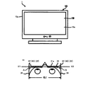
図1は、本実施形態に係る立体視映像表示システムを示す図であって、視聴者が画面を見ている状態を示す図である。立体視映像表示システム1は、立体視映像表示装置としてのデジタルテレビジョン放送受信装置10(本体装置)と、立体視眼鏡装置30と、を有している。この立体視映像表示システム1では、視聴者は、デジタルテレビジョン放送受信装置10の画面に出力された立体視用映像を、立体視眼鏡装置30を装着した状態で見ることで、立体視を体感することができる。
FIG. 1 is a diagram illustrating a stereoscopic video display system according to the present embodiment, and is a diagram illustrating a state in which a viewer is looking at a screen. The stereoscopic video display system 1 includes a digital television broadcast receiver 10 (main device) as a stereoscopic video display device and a
図2は、本実施形態に係るデジタルテレビジョン放送受信装置の構成を示す図である。デジタルテレビジョン放送受信装置10は、通常の平面視(二次元)表示用の映像信号に基づく映像表示、及び、立体視(三次元)表示用の映像信号に基づく映像表示を行うことが可能な映像表示装置である。
FIG. 2 is a diagram showing a configuration of the digital television broadcast receiving apparatus according to the present embodiment. The digital
アンテナ11で受信したデジタルテレビジョン放送信号は、入力端子10aを介してチューナ部12に供給されることにより、所望のチャンネルの放送信号が選局される。そして、このチューナ部12で選局された放送信号は、復調復号部13に供給されてデジタルの映像信号及び音声信号等に復元された後、信号処理部14に出力される。
The digital television broadcast signal received by the antenna 11 is supplied to the
信号処理部14は、復調復号部13から供給されたデジタルの映像信号及び音声信号に対して、それぞれ所定のデジタル信号処理を施している。この信号処理部14が行う所定のデジタル信号処理には、通常の平面視表示用の映像信号を立体視表示用の映像信号に変換する処理や、立体視表示用の映像信号を平面視表示用の映像信号に変換する処理等も含まれている。そして、信号処理部14は、デジタルの映像信号を合成処理部15に出力し、デジタルの音声信号を音声処理部16に出力している。
The
このうち、合成処理部15は、信号処理部14から供給されるデジタルの映像信号に、OSD(On Screen Display)信号生成部17で生成されるOSD信号を重畳して出力している。この場合、合成処理部15は、信号処理部14から供給される映像信号が通常の平面視表示用の映像信号であれば、その映像信号にOSD信号生成部17から供給されたOSD信号をそのまま重畳して出力している。
Among these, the
また、この合成処理部15は、信号処理部14から供給される映像信号が立体視表示用の映像信号である場合、詳細は後述するが、OSD信号生成部17から供給されたOSD信号に対して、入力された立体視表示用の映像信号に対応した立体視表示用の信号処理を施した後、そのOSD信号を入力映像信号に重畳して出力している。
In addition, when the video signal supplied from the
そして、合成処理部15から出力されたデジタルの映像信号は、映像処理部18に供給される。映像処理部18は、入力されたデジタルの映像信号を、後段の、例えば液晶表示パネル等を有する平面型の映像出力部19で表示可能なフォーマットのアナログ映像信号に変換している。そして、この映像処理部18から出力されたアナログ映像信号が、映像出力部19に供給されて、映像出力部19が映像を画面19aに出力する。映像出力部19は、平面視用映像と立体視用映像とを選択的に出力(表示)可能である。
The digital video signal output from the
本体側通信部20は、合成処理部15に接続され、後述する眼鏡制御部159から出力された左眼用及び右眼用のシャッタ制御信号を各立体視眼鏡装置30に送信する。なお、本体側通信部20の通信方式は、特に問わず、例えば、Bluetooth(登録商標)や赤外線通信方式、DLP−LINK(登録商標)方式等を用いることができる。
The main body
ここで、図3は、合成処理部15の構成を示す図である。信号処理部14から出力されるデジタルの映像信号は、入力端子15aを介して映像変換部151に供給される。映像変換部151は、入力された映像信号が立体視(三次元)表示用の映像信号である場合、その映像信号を特定の映像フォーマットに変換して、画質制御部152及び視差量抽出部153に出力している。
Here, FIG. 3 is a diagram illustrating a configuration of the
立体視表示用の映像信号には、1フレーム同期期間内で左眼用映像フレーム後に右眼用映像フレームを送出するフレームパッキング方式や、1水平期間内で左眼用映像ライン後に右眼用映像ラインを送出するサイドバイサイド方式等、様々な映像フォーマットが存在する。さらに、各映像フォーマットの中でも、映像のサイズや走査方式(インタレース/プログレッシブ)等が種々存在する。 For video signals for stereoscopic display, a frame packing method in which a right-eye video frame is sent after a left-eye video frame within one frame synchronization period, or a right-eye video after a left-eye video line within one horizontal period There are various video formats such as a side-by-side system for sending out lines. Furthermore, among the various video formats, there are various video sizes, scanning methods (interlace / progressive), and the like.
このため、本実施形態では、映像変換部151が、入力された立体視表示用の映像信号に対して、スケーリング処理やIP(Interlace/Progressive)変換処理等の処理を施すことにより、所定の映像サイズ(例えば、水平方向1920画素×垂直方向1080ライン)のフレームパッキング方式の映像フォーマットに変換し、垂直同期信号に同期させて画質制御部152及び視差量抽出部153に出力するものとする。
For this reason, in the present embodiment, the
このうち、画質制御部152は、入力された映像信号に対して、本体制御部22の制御に基づいた明るさ調整、コントラスト調整及び色相調整等の画質調整処理を施し、垂直同期信号に同期させて合成部154に出力している。
Among these, the image
また、上記視差量抽出部153は、映像変換部151により、フレームパッキング方式の映像フォーマットに変換された立体視表示用の映像信号に対して、その左眼用映像フレームと右眼用映像フレームとの間の映像の比較を行ない、視差量を抽出している。
In addition, the parallax
この視差量抽出部153による視差量の抽出処理は、左眼用映像フレームに表示されている物体の位置を基準として、右眼用映像フレームに表示されている同じ物体の左右方向の位置ずれを、画素数で示すことによって行なわれる。この視差量抽出処理は、連続するフレームで表示される同じ物体の動き位置を検出するための動きベクトルの技術を利用することで容易に実現することができる。具体的には、画面上で水平方向に配列された画素に、左側から右側に向けて番号を振り、左眼用映像フレームに表示されている或る物体の所定位置の画素の番号から、右眼用映像フレームに表示されているその物体の同じ所定位置の画素の番号を減算することにより、視差量を画素数で示すことができる。
This parallax amount extraction processing by the parallax
この場合、視差量が負値のときは、左眼用映像より右眼用映像が右側に存在することになり、その物体は画面よりも奥側で結像される映像となる。また、視差量が正値のときは、左眼用映像より右眼用映像が左側に存在することになり、その物体は画面よりも手前で結像される映像となる。 In this case, when the parallax amount is a negative value, the right-eye image is present on the right side of the left-eye image, and the object is an image formed on the back side of the screen. When the parallax amount is a positive value, the right-eye image is present on the left side of the left-eye image, and the object is an image formed in front of the screen.
また、視差量抽出部153は、入力端子15bを介して入力される本体制御部22からの制御信号に応じて、上述した視差量の値をゼロ値に切り替える。ここで、視差量がゼロ値の状態は、左眼用映像及び右眼用映像はともに同位置となり、画面上に結像される映像、即ち平面視(二次元)映像となる。
Further, the parallax
そして、視差量抽出部153によって抽出された視差量は、OSD位置算出部155に供給される。このOSD位置算出部155は、入力された視差量に基づいて、OSDを立体視表示させる際の表示位置を補正する計算を行ない、その計算結果を示す視差制御信号を出力している。
Then, the parallax amount extracted by the parallax
具体的に、OSD位置算出部155は、視差量抽出部153で抽出された視差量が時間軸方向の変動がない状態、または、視差量が時間軸方向に緩やかに変動している映像表示状態のときに、OSDを立体視表示させる際の表示位置を補正する計算を実行する。すなわち、視差量が時間軸方向に激しく変動している場合は、映像が奥行き方向に激しく動いている状態であり、この状態ではユーザは映像に意識が向いているため、重畳するOSDも奥行き方向に激しく動くと見苦しくなるからである。このため、OSD位置算出部155は、視差量が激しく変動している状態では、視差量の変動がすくないときに算出した結果を示す視差制御信号を出力している。なお、視差量がゼロ値の状態では、表示位置の補正は行わないものとする。
Specifically, the OSD
そして、このOSD位置算出部155から出力される視差制御信号は、OSD立体変換部156に供給される。このOSD立体変換部156には、上記OSD信号生成部17から出力されるOSD信号が、入力端子15cを介して供給されている。このOSD立体変換部156は、視差制御信号に基づいて、入力されたOSD信号から、左眼用映像フレームに重畳する左眼用OSD信号と、右眼用映像フレームに重畳する右眼用OSD信号とを生成し、OSDバッファ157に出力し記憶させている。
Then, the parallax control signal output from the OSD
そして、合成部154で合成された映像信号は、フレーム変換部158に供給され、垂直同期周波数が2倍に変換されて、つまり、フレーム周波数が倍速化された後、出力端子15dから上記映像処理部18を介して映像出力部19に出力される。これにより、映像出力部19が、左眼用映像と右眼用映像とが交互に切り替わる立体視用映像を画面19aに出力する。
Then, the video signal synthesized by the synthesizing
また、上記フレーム変換部158で生成されるフレーム同期信号は、眼鏡制御部159に供給される。眼鏡制御部159は、フレーム変換部158から供給されたフレーム同期信号に同期して左眼用及び右眼用のシャッタ制御信号を生成し、出力端子15eから本体側通信部20を介して立体視眼鏡装置30に出力する。
Further, the frame synchronization signal generated by the
図2に戻り、音声処理部16は、信号処理部14から入力されたデジタルの音声信号を、後段のスピーカ(音声出力部)21で再生可能なフォーマットのアナログ音声信号に変換する。そして、この音声処理部16から出力されたアナログ音声信号が、スピーカ21に供給されることにより、スピーカ21が音声を再生出力する。
Returning to FIG. 2, the
また、図1および図2に示すように、デジタルテレビジョン放送受信装置10の画面19aの下方には本体側通信部20が設けられている。
As shown in FIGS. 1 and 2, a main body
ここで、デジタルテレビジョン放送受信装置10では、上記した各種の受信動作を含むその全ての動作が本体制御部22によって統括的に制御されている。この本体制御部22は、CPU(Central Processing Unit)22aを内蔵しており、デジタルテレビジョン放送受信装置10の本体に設置された操作部23からの操作情報を受けて、または、リモートコントローラ40から送出され受信部24で受信した操作情報を受けて、その操作内容が反映されるように各部をそれぞれ制御している。また、この本体制御部22は、検出部60の検出結果に応じて、映像出力部19やスピーカ21を制御する。
Here, in the digital television
この場合、本体制御部22は、メモリ部22bを利用している。このメモリ部22bは、主として、CPU22aが実行する制御プログラムを格納したROM(Read Only Memory)と、該CPU22aに作業エリアを提供するためのRAM(Random Access Memory)と、各種の設定情報及び制御情報等が格納される不揮発性メモリとを有している。
In this case, the main
また、本体制御部22には、ディスクドライブ部25が接続されている。このディスクドライブ部25は、例えばDVD(Digital Versatile Disk)等の光ディスクMを着脱自在とするもので、装着された光ディスクMに対してデジタルデータの記録再生を行なう機能を有している。
A
そして、本体制御部22は、ユーザによる操作部23やリモートコントローラ40の操作に基づいて、上記復調復号部13から得られるデジタルの映像信号及び音声信号を、記録再生処理部26によって暗号化し所定の記録フォーマットに変換した後、ディスクドライブ部25に供給して光ディスクMに記録させるように制御することができる。
The main
また、本体制御部22は、ユーザによる操作部23やリモートコントローラ40の操作に基づいて、ディスクドライブ部25により光ディスクMからデジタルの映像信号及び音声信号を読み出させ、上記記録再生処理部26によって復号化した後、信号処理部14に供給することによって、以後、上記した映像表示及び音声再生に供させるように制御することができる。
Further, the main
さらに、本体制御部22には、HDD(Hard Disk Drive)27が接続されている。本体制御部22は、ユーザによる操作部23やリモートコントローラ40の操作に基づいて、上記復調復号部13から得られるデジタルの映像信号及び音声信号を、記録再生処理部26によって暗号化し所定の記録フォーマットに変換した後、HDD27に記録させるように制御することができる。
Furthermore, an HDD (Hard Disk Drive) 27 is connected to the main
また、本体制御部22は、ユーザによる操作部23やリモートコントローラ40の操作に基づいて、HDD27からデジタルの映像信号及び音声信号を読み出させ、上記記録再生処理部26によって復号化した後、信号処理部14に供給することによって、以後、上記した映像表示及び音声再生に供させるように制御することができる。
Further, the main
さらに、上記デジタルテレビジョン放送受信装置10には、入力端子10bが接続されている。この入力端子10bは、デジタルテレビジョン放送受信装置10の外部からデジタルの映像信号及び音声信号を直接入力するためのものである。この入力端子10bを介して入力されたデジタルの映像信号及び音声信号は、本体制御部22の制御に基づいて、記録再生処理部26を介した後、信号処理部14に供給されて、以後、上記した映像表示及び音声再生に供される。
Furthermore, an
また、この入力端子10bを介して入力されたデジタルの映像信号及び音声信号は、本体制御部22の制御に基づいて、記録再生処理部26を介した後、ディスクドライブ部25による光ディスクMに対しての記録再生や、HDD27に対しての記録再生に供される。
Further, the digital video signal and audio signal input through the
なお、本体制御部22は、ユーザによる操作部23やリモートコントローラ40の操作に基づいて、ディスクドライブ部25とHDD27との間で、光ディスクMに記録されているデジタルの映像信号及び音声信号をHDD27に記録したり、HDD27に記録されているデジタルの映像信号及び音声信号を光ディスクMに記録したりすることも制御している。
The main
また、本体制御部22には、ネットワークインタフェース28が接続されている。このネットワークインタフェース28は、外部のネットワークNに接続されている。そして、ネットワークインタフェース28はネットワークNを介し、図示しない外部装置との間で通信を行う。このため、本体制御部22は、ネットワークインタフェース28を介し、ネットワークNに接続された外部装置にアクセスして情報通信を行なうことにより、そこで提供しているサービスを利用することができるようになっている。
A network interface 28 is connected to the main
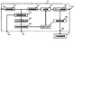
次に、図4を参照して、立体視眼鏡装置30について説明する。図4は、本実施形態に係る立体視眼鏡装置30の構成を示す図である。
Next, the
立体視眼鏡装置30は、デジタルテレビジョン放送受信装置10の映像出力部19が出力する立体視用映像用である。詳細には、立体視眼鏡装置30は、左眼用映像の出力及び非出力に同期して左眼の視界を解放及び遮蔽するとともに、右目用映像の出力及び非出力に同期して右眼の視界を解放及び遮蔽する。図4に示すように、立体視眼鏡装置30は、液晶シャッタ眼鏡31と、眼鏡側通信部32と、シャッタ駆動部34と、立体視眼鏡装置30の左右のつる39の幅または眼鏡のレンズ面とつる39の角度を測るセンサ62(詳細は後述する)と、判定部(判定手段)60と、制御部35とを備えている。
The
この立体視眼鏡装置30は、電池などの電源37を搭載しており、この電源37から供給される電力によって動作する。
The
液晶シャッタ眼鏡31は、左眼の視界を開放又は遮蔽するための左眼液晶シャッタ(Lシャッタ)311と、右眼の視界を開放又は遮蔽するための右眼液晶シャッタ(Rシャッタ)312とを有している。ユーザは、この液晶シャッタ眼鏡31(立体視眼鏡装置30)を装着して、交互に表示される左眼用の画像と右眼用の画像とを左眼と右眼とで交互に鑑賞することにより、立体視を体感する。
The liquid
眼鏡側通信部32は、本体側通信部20の送信方式に対応した受信装置であって、デジタルテレビジョン放送受信装置10の本体側通信部20から送信された左眼用及び右眼用のシャッタ制御信号を受信する。
The eyeglass-
シャッタ駆動部34は、制御部35から入力される制御信号に従い、Lシャッタ311及びRシャッタ312を開閉することで、デジタルテレビジョン放送受信装置10に表示される映像(光)の透過状態と不透過状態を実現する。
The
制御部35は、上記各部の動作を統括的に制御している。この制御部35は、CPU35aやメモリ部35bを内蔵している。メモリ部35bは、主として、CPU35aが実行する制御プログラムを格納したROMと、CPU35aに作業エリアを提供するためのRAMと、各種の設定情報及び制御情報等が格納される不揮発性メモリとを有している。
The
制御部35は、眼鏡側通信部32から入力される左眼用及び右眼用のシャッタ制御信号に基づいて、Lシャッタ311及びRシャッタ312の開閉を制御する。具体的には、制御部35は、シャッタ制御信号に基づき、左眼用映像の出力及び非出力に同期して、Lシャッタ311に、左眼の視界を解放及び遮蔽させるとともに、右目用映像の出力及び非出力に同期して、Rシャッタ312に、右眼の視界を解放及び遮蔽させる。また、制御部35は、判定部60から入力された判定結果を、眼鏡側通信部32を用いて、デジタルテレビジョン放送受信装置10の本体側通信部20に送信する。
The
センサ62は、本実施形態では圧力センサと角度センサの両方をそれぞれ持っており、図1に示すように、立体視眼鏡装置30の左右方向で相互に離間して配置され、フレーム31aに固定されている。なお、場合によっては、センサ62は圧力センサのみであってもよく、また角度センサのみであってもよい。さらに、センサ62は圧力センサや角度センサ以外のセンサであってもよい。また、ここでは立体視眼鏡装置30はシャッタ方式として説明したが、それは一例であり直線偏光フィルター方式など他の方式でもよいことは言うまでもない。
In the present embodiment, the
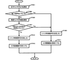
以下、図5に立体視眼鏡装置30側で3D視聴機能を制御する処理フローを示す。
FIG. 5 shows a processing flow for controlling the 3D viewing function on the
例えば、立体視眼鏡装置30が人の頭(耳)に装着されたとき、圧力センサは左右のつる39と人の頭との圧力を測定し、測定結果を判定部60に送信する(ステップST501)。すなわち、圧力センサは左側のつる39と右側のつる39との幅Z(図1に示す)を測定する。判定部60は、圧力センサによって測定された測定値(幅Z)と制御部35から送られる基準値とを比較し、測定値(幅Z)が基準値よりも小さいか否かを判定する(ステップST503)。測定値(幅Z)が基準値よりも小さいと判定した場合には(ステップST503のY)、ステップST511の処理へ進む。
For example, when the
判定部60は測定値(幅Z)が基準値よりも大きいと判定した場合(ステップST503のN)、次に角度センサが眼鏡装置30のレンズ面(図1の線X1−X2)とつる39との角度A、角度Bを測定する。判定部60は測定値(角度Aまたは角度B)が基準値よりも小さいと判定した場合には(ステップST507のY)、ステップST511の処理へ進む。判定部60は測定値(角度Aまたは角度B)が基準値よりも大きいと判定した場合(ステップST507のN)、判定部60は制御部35へその旨通知し、制御部35はこの通知を受けて使用者が大人であると判断する。制御部35はデジタルテレビジョン放送受信装置10側からシャッタ制御信号が送られてきたら、デジタルテレビジョン放送受信装置10側の3D視聴機能が有効であると判断して3D視聴を実行する。すなわち、制御部35は眼鏡側通信部32から入力される左眼用及び右眼用のシャッタ制御信号に基づいて、シャッタ駆動部34を介してLシャッタ311及びRシャッタ312の開閉を制御する(ステップST509)。
If the
次に、ステップST511の処理に戻る。判定部60は測定値(幅Z)が基準値よりも小さいと判定したか、または、測定値(角度A、角度B)が基準値よりも小さいと判定した場合、判定部60は制御部35へその旨通知する。制御部35はこの通知を受けて使用者が幼児であると判断する。制御部35は、デジタルテレビジョン放送受信装置10側からシャッタ制御信号を受信したか確認する。そして、シャッタ制御信号を受信したら(ステップST511のY)、3D映像信号であると判断し、制御部35は3D視聴機能を無効にすべく、シャッタ駆動部34を介してLシャッタ311及びRシャッタ312が開閉しないように制御する(ステップST513)。そうすることで、デジタルテレビジョン放送受信装置10から3D映像信号を受信しても視聴者は3D視聴ができなくなる。
Next, the process returns to step ST511. When the
また、シャッタ制御信号を受信しなかった場合(ステップST511のN)、デジタルテレビジョン放送受信装置10側の3D視聴機能が無効であると判断し、2D視聴を可能とする(ステップST515)。
If the shutter control signal is not received (N in step ST511), it is determined that the 3D viewing function on the digital television
このように、3D映像視聴用の眼鏡を使用して3D映像信号の視聴を行う際、眼鏡装置30の左右のつる39の幅もしくは角度A、角度Bを検出し、基準値より少ない(頭の幅が小さい)場合は、使用者が幼児であると判断し、3D視聴機能を無効にし、幼児の3D視聴を抑制することができる。
In this way, when viewing 3D video signals using glasses for viewing 3D video, the width or angle A or angle B of the left and
なお、図5は3D視聴機能を有効にするか無効にするかの判断条件の一例である。この例では、つる39の幅もしくは角度A、Bのどちらか一方でも該当すれば3D視聴機能を無効にしている。ただし、判断条件は必ずしもこの通りでなくとも構わず、例えば、つる39の幅と角度A、Bのいずれか一方のみで判断しても良いし、どちらか一方の検出結果を優先して判断しても良い。また、角度Aまたは角度Bのどちらか一方が基準値より小さかった場合も3D視聴機能を無効にする。
FIG. 5 is an example of a determination condition for enabling or disabling the 3D viewing function. In this example, the 3D viewing function is disabled if either the width of the
次に、デジタルテレビジョン放送受信装置10側で3D視聴機能を制御する処理フローを図6に示す。
Next, FIG. 6 shows a processing flow for controlling the 3D viewing function on the digital television
図6のステップST601からST607までの処理は、図5で説明したステップST501からST507までの処理と同じであるため、説明は省略する。 The processing from step ST601 to ST607 in FIG. 6 is the same as the processing from step ST501 to ST507 described with reference to FIG.
ステップST603またはステップST607において、判定部60は測定値(幅Z、または角度A、角度B)が基準値よりも小さいと判断した場合、その旨制御部35へ通知し、制御部35は使用者が幼児であると判断する。制御部35は眼鏡側通信部32を介してデジタルテレビジョン放送受信装置10の本体側通信部20へその旨通知する。そして、本体側通信部20から本体制御部22に通知されると、本体制御部22は合成処理部15に対してシャッタ制御信号を生成しないように制御する(ステップST609)。また、本体制御部22内の出力制御部22cは映像出力部19の3D映像信号(出力)を停止させ、3D視聴ができないように制御する。すなわち、3D視聴機能を無効にする(ステップST611)。
In step ST603 or step ST607, when the
次に、ステップST607がNoの場合、(立体視眼鏡装置30側の)制御部35は使用者が大人であると判断して、眼鏡側通信部32を介してデジタルテレビジョン放送受信装置10の本体側通信部20へその旨通知する。そして、本体側通信部20が(方送受信装置10側の)本体制御部22に通知する。大人である情報が本体制御部22に通知されると、本体制御部22は合成処理部15に対してシャッタ制御信号を生成するように制御する(ステップST613)。また、本体制御部22内の出力制御部22cは映像出力部19の3D映像信号を出力するように制御する。すなわち、3D視聴機能を有効にする(ステップST615)。
Next, when step ST607 is No, the control unit 35 (on the side of the stereoscopic eyeglass device 30) determines that the user is an adult, and the digital television
このように、3D映像視聴用の眼鏡を使用して3D映像信号の視聴を行う際、眼鏡装置30の左右のつる39の幅もしくは角度A、角度Bを検出し、基準値より小さい(頭の幅が小さい)場合は、使用者が幼児であると判断し、デジタルテレビジョン放送受信装置10側で3D視聴機能を無効にし、幼児の3D視聴を抑制することができる。
In this way, when viewing 3D video signals using glasses for viewing 3D video, the width or angle A or angle B of the left and
上記説明したように、立体視眼鏡装置を大人が装着しているのか幼児が装着しているのかを判断し、立体視眼鏡装置側またはデジタルテレビジョン放送受信装置側で3D視聴機能を制御することができる。3D映像の視聴は幼児の発育に影響がある可能性があり、3D視聴用機器ではカタログや取扱説明書などで幼児には視聴させないよう注意喚起をしている。本発明はこういった注意喚起のみではなく機器側に視聴を制限する機能を搭載することにより、より確実に幼児の3D映像視聴を抑制するものである。 As described above, it is determined whether an adult or an infant is wearing a stereoscopic glasses apparatus, and the 3D viewing function is controlled on the stereoscopic glasses apparatus side or the digital television broadcast receiver side. Can do. Viewing 3D images may affect the growth of young children, and 3D viewing devices are alerted to prevent them from viewing with catalogs and instruction manuals. In the present invention, not only such alerting but also a function for restricting viewing on the device side is installed, so that 3D video viewing of an infant is more reliably suppressed.
なお、本実施形態では、立体視眼鏡装置やデジタルテレビジョン放送受信装置側で3D視聴機能を制御しているが、大人でも頭の小さい人はいるため使用者が設定メニュー等で有効または無効を変更することも可能である。 In this embodiment, the 3D viewing function is controlled on the stereoscopic eyeglass device or the digital television broadcast receiver side. However, since there are even adults with small heads, the user can enable or disable the setting menu etc. It is also possible to change.
本発明のいくつかの実施形態を説明したが、これらの実施形態は、例として提示したものであり、発明の範囲を限定することは意図していない。これら新規な実施形態は、その他の様々な形態で実施されることが可能であり、発明の要旨を逸脱しない範囲で、種々の省略、置き換え、変更を行うことができる。これら実施形態やその変形は、発明の範囲や要旨に含まれるとともに、特許請求の範囲に記載された発明とその均等の範囲に含まれる。 Although several embodiments of the present invention have been described, these embodiments are presented by way of example and are not intended to limit the scope of the invention. These novel embodiments can be implemented in various other forms, and various omissions, replacements, and changes can be made without departing from the scope of the invention. These embodiments and modifications thereof are included in the scope and gist of the invention, and are included in the invention described in the claims and the equivalents thereof.
1…立体視映像表示システム
10…デジタルテレビジョン放送受信装置(立体視映像表示装置)
19a…画面
19…映像出力部
21…スピーカ(音声出力部)
22…本体制御部
22c…出力制御部(出力制御手段)
30…立体視眼鏡装置
32…眼鏡側通信部
35…制御部
39…つる
60…判定部
62…センサ
DESCRIPTION OF SYMBOLS 1 ... Stereoscopic
19a ...
22 ... Main
30 ...
Claims (5)
使用者が前記立体視眼鏡装置を装着したときに、前記立体視眼鏡装置の左右のつるを用いて前記使用者の頭の大きさを測定する測定部と、
前記測定部が測定した測定値が基準値よりも小さいかを判定する判定部と、
前記判定部の判定結果に応じて、前記3D映像を表示させないように制御する制御部と
を具備することを特徴とする立体視眼鏡装置。 In a stereoscopic eyeglass device capable of displaying 3D video,
A measurement unit that measures the size of the user's head using the left and right vines of the stereoscopic glasses device when the user wears the stereoscopic glasses device;
A determination unit for determining whether the measurement value measured by the measurement unit is smaller than a reference value;
A stereoscopic eyeglass device comprising: a control unit that controls not to display the 3D video according to a determination result of the determination unit.
を特徴とする請求項1記載の立体視眼鏡装置。 The stereoscopic eyeglass device according to claim 1, wherein the measurement unit is a pressure sensor that measures widths of left and right vines of the stereoscopic eyeglass device.
サであることを特徴とする請求項1記載の立体視眼鏡装置。 The stereoscopic eyeglass device according to claim 1, wherein the measurement unit is an angle sensor that measures an angle between the lens surface of the stereoscopic eyeglass device and the hook.
前記測定部は、前記立体視眼鏡装置の左右方向で相互に離間して配置され、前記フレームに固定されることを特徴とする請求項1記載の立体視眼鏡装置。 The stereoscopic glasses apparatus has a frame,
The stereoscopic eyeglass device according to claim 1, wherein the measuring units are arranged apart from each other in the left-right direction of the stereoscopic eyeglass device and are fixed to the frame.
Priority Applications (2)
| Application Number | Priority Date | Filing Date | Title |
|---|---|---|---|
| JP2012044805A JP5349633B2 (en) | 2012-02-29 | 2012-02-29 | Stereoscopic eyeglass device, stereoscopic image display device and control method thereof |
| US13/777,756 US20130222536A1 (en) | 2012-02-29 | 2013-02-26 | 3d glasses, 3d image display apparatus and a control method thereof |
Applications Claiming Priority (1)
| Application Number | Priority Date | Filing Date | Title |
|---|---|---|---|
| JP2012044805A JP5349633B2 (en) | 2012-02-29 | 2012-02-29 | Stereoscopic eyeglass device, stereoscopic image display device and control method thereof |
Publications (2)
| Publication Number | Publication Date |
|---|---|
| JP2013183236A JP2013183236A (en) | 2013-09-12 |
| JP5349633B2 true JP5349633B2 (en) | 2013-11-20 |
Family
ID=49002435
Family Applications (1)
| Application Number | Title | Priority Date | Filing Date |
|---|---|---|---|
| JP2012044805A Expired - Fee Related JP5349633B2 (en) | 2012-02-29 | 2012-02-29 | Stereoscopic eyeglass device, stereoscopic image display device and control method thereof |
Country Status (2)
| Country | Link |
|---|---|
| US (1) | US20130222536A1 (en) |
| JP (1) | JP5349633B2 (en) |
Families Citing this family (2)
| Publication number | Priority date | Publication date | Assignee | Title |
|---|---|---|---|---|
| JP2015119464A (en) * | 2013-11-12 | 2015-06-25 | セイコーエプソン株式会社 | Display device and control method of the same |
| CN103760973B (en) * | 2013-12-18 | 2017-01-11 | 微软技术许可有限责任公司 | Reality-enhancing information detail |
Family Cites Families (11)
| Publication number | Priority date | Publication date | Assignee | Title |
|---|---|---|---|---|
| JP3081512B2 (en) * | 1995-06-21 | 2000-08-28 | 三洋電機株式会社 | 3D image device |
| JP3469854B2 (en) * | 2000-05-12 | 2003-11-25 | 日本電信電話株式会社 | 3D display |
| US7784938B2 (en) * | 2007-05-09 | 2010-08-31 | Dolby Laboratories Licensing Corporation | Method and system for shaped glasses and viewing 3D images |
| US20110012896A1 (en) * | 2009-06-22 | 2011-01-20 | Ji Maengsob | Image display apparatus, 3d glasses, and method for operating the image display apparatus |
| JP2011028633A (en) * | 2009-07-28 | 2011-02-10 | Sony Corp | Information processing apparatus, method and program |
| KR101621907B1 (en) * | 2010-02-02 | 2016-05-17 | 삼성전자주식회사 | Display apparatus and method for providing 3D Image applied to the same and system for providing 3D Image |
| JP4951076B2 (en) * | 2010-03-05 | 2012-06-13 | 株式会社東芝 | Display device, system, and glasses |
| EP2365699B1 (en) * | 2010-03-11 | 2018-10-17 | Samsung Electronics Co., Ltd. | Method for adjusting 3D image quality, 3D display apparatus, 3D glasses, and system for providing 3D image |
| KR20110114257A (en) * | 2010-04-13 | 2011-10-19 | 삼성전자주식회사 | 3-dimension display apparatus and method for setting display mode thereof, and system for providing 3d display |
| KR101598926B1 (en) * | 2010-04-16 | 2016-03-02 | 삼성전자 주식회사 | Shutter glasses |
| JP2012029007A (en) * | 2010-07-22 | 2012-02-09 | Toshiba Corp | Video output device and video output method |
-
2012
- 2012-02-29 JP JP2012044805A patent/JP5349633B2/en not_active Expired - Fee Related
-
2013
- 2013-02-26 US US13/777,756 patent/US20130222536A1/en not_active Abandoned
Also Published As
| Publication number | Publication date |
|---|---|
| JP2013183236A (en) | 2013-09-12 |
| US20130222536A1 (en) | 2013-08-29 |
Similar Documents
| Publication | Publication Date | Title |
|---|---|---|
| JP2012015774A (en) | Stereoscopic image processing device and stereoscopic image imaging method | |
| JP5025772B2 (en) | Stereoscopic glasses and stereoscopic video display system | |
| US20130038611A1 (en) | Image conversion device | |
| US8994797B2 (en) | Display system, display device and display assistance device | |
| KR101598926B1 (en) | Shutter glasses | |
| WO2012117703A1 (en) | Three-dimensional image processing device, three-dimensional image processing method, spectacles device for viewing three-dimensional image, integrated circuit for three-dimensional image processing device, optical disk playback device, three-dimensional video signal playback device, and three-dimensional video signal display device | |
| JP2011029949A (en) | Video display apparatus | |
| US8957950B2 (en) | Electronic apparatus and image output method | |
| JP5349633B2 (en) | Stereoscopic eyeglass device, stereoscopic image display device and control method thereof | |
| JP2013225745A (en) | Stereoscopic video display system, stereoscopic video projection device, active shutter glasses, and parallax amount control method | |
| JP2013051614A (en) | Video processing apparatus and video processing method | |
| JP2012231275A (en) | Image processing apparatus and image processing method, display system, video generating apparatus, and reproduction apparatus | |
| JP5010732B2 (en) | Stereoscopic image processing apparatus and stereoscopic image processing method | |
| JP2012095050A (en) | Synchronization device and synchronization method | |
| JP4937390B2 (en) | 3D image display device and 3D image glasses | |
| KR101768538B1 (en) | Method for adjusting 3-Dimension image quality, 3D display apparatus, 3D glasses and System for providing 3D image | |
| JP5465083B2 (en) | 3D image display device and 3D image display system | |
| JP2010283653A (en) | Video display system, eyeglass device, and television system | |
| JP2011176397A (en) | Video signal converter and electronic device | |
| US20150189257A1 (en) | Electronic device and method for controlling the same | |
| JP2015039066A (en) | Stereoscopic video display system, stereoscopic video display device, and output control method | |
| JP2012222427A (en) | Video playback device | |
| JP2011259262A (en) | Method and system for displaying battery remaining quantity of electronic eyeglasses, electronic eyeglasses, and display apparatus | |
| JP2013046297A (en) | Three-dimensional video display device and tilt control method | |
| JP5586403B2 (en) | Video data transmitting apparatus and video data transmitting method |
Legal Events
| Date | Code | Title | Description |
|---|---|---|---|
| TRDD | Decision of grant or rejection written | ||
| A01 | Written decision to grant a patent or to grant a registration (utility model) |
Free format text: JAPANESE INTERMEDIATE CODE: A01 Effective date: 20130723 |
|
| A61 | First payment of annual fees (during grant procedure) |
Free format text: JAPANESE INTERMEDIATE CODE: A61 Effective date: 20130820 |
|
| LAPS | Cancellation because of no payment of annual fees |