JP5349365B2 - Image projection device and image display device - Google Patents
Image projection device and image display device Download PDFInfo
- Publication number
- JP5349365B2 JP5349365B2 JP2010033759A JP2010033759A JP5349365B2 JP 5349365 B2 JP5349365 B2 JP 5349365B2 JP 2010033759 A JP2010033759 A JP 2010033759A JP 2010033759 A JP2010033759 A JP 2010033759A JP 5349365 B2 JP5349365 B2 JP 5349365B2
- Authority
- JP
- Japan
- Prior art keywords
- light
- emission amount
- command value
- distance
- screen
- Prior art date
- Legal status (The legal status is an assumption and is not a legal conclusion. Google has not performed a legal analysis and makes no representation as to the accuracy of the status listed.)
- Active
Links
Images


Description
この発明は、画像投影装置および画像表示装置に関し、特に、光源から出射した光を集光後、スキャナを用いてスクリーンに投射する光学系を有する投射型の画像投影装置および画像表示装置に関するものである。 The present invention relates to an image projection apparatus and an image display apparatus, and more particularly to a projection-type image projection apparatus and an image display apparatus having an optical system for projecting light emitted from a light source onto a screen using a scanner. is there.
ユーザに映像を提供する手段として、さまざまな方式の画像表示装置が開発されている。例えば、表示デバイスに液晶やプラズマを使った薄型テレビは、CRT(Cathode Ray Tube)を駆逐する勢いで急速に普及している。また、DMD(Digital Mirror Device、登録商標)やHTPS(High Temperature Poly-Silicon)、LCOS(Liquid Crystal on Silicon)といった、いわゆるマイクロ・デバイスを用いた投射型の画像表示手法は、データプロジェクタや背面投射型テレビといった、主に大画面表示装置として普及している。 Various types of image display devices have been developed as means for providing video to the user. For example, flat-screen televisions using liquid crystal or plasma as display devices are rapidly spreading with the momentum to drive out CRT (Cathode Ray Tube). Projection-type image display methods using so-called micro devices such as DMD (Digital Mirror Device (registered trademark)), HTPS (High Temperature Poly-Silicon), and LCOS (Liquid Crystal on Silicon) are known as data projectors and rear projections. Widely used as large-screen display devices such as type televisions.
また、液晶やマイクロ・デバイスの光源として、従来の冷陰極管や高圧水銀ランプといったものに加え、LED(Light Emitting Diode)やレーザなどが採用され始めたことで、色再現範囲の拡大や消費電力の低減が進んでいる。 In addition to conventional cold cathode fluorescent lamps and high-pressure mercury lamps as light sources for liquid crystals and micro devices, LEDs (Light Emitting Diodes) and lasers have begun to be used to increase the color reproduction range and power consumption. Reduction is progressing.
また、MEMS(Micro Electro Mechanical System)技術が進歩し、小型のスキャナ装置を作ることが可能になったことに加え、3原色とも半導体レーザが開発されたこともあり、近年スキャナを用いた投射型画像表示装置が注目を集めている。 In addition to the advancement of MEMS (Micro Electro Mechanical System) technology, it has become possible to make a compact scanner device, and in addition, semiconductor lasers have been developed for all three primary colors. Image display devices are attracting attention.
ところで、レーザを用いた画像表示装置では、観察に適した画像の表示や画像表示の安全性が求められる。例えば、特許文献1の走査型プロジェクタでは、レーザ光の走査が正常に行われない状態にあるときにレーザ光の発生を直接的に遮断している。
By the way, in an image display device using a laser, display of an image suitable for observation and safety of image display are required. For example, the scanning projector disclosed in
しかしながら、上記従来の技術は、スキャナの不具合に対する処理技術であり、光路上に不具合が生じて観察に適さない映像を表示してしまう場合には対応できなかった。例えばスクリーンに孔が開いている場合、前面投射型の画像表示装置においては部分的に映像が欠落する。また、背面投射型の画像表示装置においては、部分的に画像が欠落することに加えて、不具合の発生箇所によっては、スクリーンの孔を光が通り抜ける。このため、スクリーンで拡散されなかった光が直接観察者の瞳孔に長時間入射してしまう等の可能性があった。また、直接瞳孔に光が入射しない場合であっても、部屋の壁等のスクリーン外の予期しない場所で不快な反射光が生成されてしまう可能性があった。 However, the above-described conventional technique is a processing technique for a problem of a scanner, and cannot cope with a case where a defect occurs on the optical path and an image unsuitable for observation is displayed. For example, when a hole is formed in the screen, a video is partially lost in the front projection type image display device. Further, in the rear projection type image display device, in addition to the partial loss of an image, light passes through a hole in the screen depending on a location where a failure occurs. For this reason, there is a possibility that light that has not been diffused by the screen may directly enter the pupil of the observer for a long time. Further, even when light does not enter the pupil directly, there is a possibility that unpleasant reflected light may be generated at an unexpected place outside the screen such as a room wall.
また、スキャナからスクリーンまでの光路上に障害物が侵入した場合、前面投射型や背面投射型の画像表示装置においては部分的に映像が欠落する。さらに、障害物表面での不快な反射光が発生する場合があった。このように、上記従来の技術では、光路上に不具合が生じた場合に、部分的な映像の欠落、瞳孔への光の長時間にわたる直接入射、予期しない位置への反射光の発生などが生じる場合があるといった問題があった。 In addition, when an obstacle enters the optical path from the scanner to the screen, the image is partially lost in the front projection type and rear projection type image display devices. Furthermore, unpleasant reflected light on the obstacle surface may occur. As described above, in the above conventional technique, when a defect occurs on the optical path, partial omission of images, direct incidence of light on the pupil for a long time, generation of reflected light at an unexpected position, and the like occur. There was a problem that there was a case.
本発明は、上記に鑑みてなされたものであって、画像表示中に発生した意図しない光を速やかに検知して画像表示を停止させる画像投影装置および画像表示装置を得ることを目的とする。 The present invention has been made in view of the above, and an object of the present invention is to obtain an image projection apparatus and an image display apparatus that quickly detect unintended light generated during image display and stop image display.
上述した課題を解決し、目的を達成するために、本発明は、発光量の指令値である発光量指令値により、出射する可視光領域の光の発光光量が制御される光源と、前記光源から出射された光をスクリーン上に走査投影する第1の光走査部と、前記光源から出射される光とは異なる波長領域の光を距離測定用の光として出射するとともに出射した光が前記スクリーンで反射されて戻ってくるまでの時間を計測することによって、自身から前記スクリーンまでの距離を測定する距離測定部と、外部入力される映像信号に基づいて、前記発光量指令値の生成に用いる指令基準値を生成する発光量指令値生成部と、前記指令基準値と前記距離測定部が測定した距離に基づいて前記発光量指令値を生成する発光量指令値変換部と、を有し、前記発光量指令値変換部は、前記距離測定部によって測定された距離と予め設定しておいた距離の許容範囲とを比較し、前記測定された距離が前記許容範囲外である場合に前記光源から光を停止させる発光量指令値を前記光源に出力するとともに、前記光源から光を停止させる発光量指令値を前記光源に出力した場合には、外部入力される出射停止の解除指示があるまで前記光源から光を停止させる発光量指令値を前記光源に出力し続けることを特徴とする。 In order to solve the above-described problems and achieve the object, the present invention provides a light source in which the amount of emitted light in the visible light region is controlled by a light emission amount command value that is a light emission amount command value, and the light source A first light scanning unit that scans and projects the light emitted from the screen onto the screen, and emits light in a wavelength region different from the light emitted from the light source as light for distance measurement, and the emitted light is emitted from the screen. A distance measuring unit that measures the distance from the screen to the screen by measuring the time until the light is reflected and returned, and is used to generate the light emission amount command value based on an externally input video signal A light emission amount command value generation unit that generates a command reference value; and a light emission amount command value conversion unit that generates the light emission amount command value based on the distance measured by the command reference value and the distance measurement unit, The luminous intensity finger Value conversion unit compares the allowable range of the distance that has been set in advance as the distance measured by the distance measuring unit, stops the light from the light source when the measurement distance is outside the allowable range A light emission amount command value to be output to the light source, and a light emission amount command value to stop light from the light source is output to the light source. The light emission amount command value for stopping the operation is continuously output to the light source .
本発明によれば、画像表示中に発生した意図しない光を速やかに検知して画像表示を停止させることが可能になるという効果を奏する。 According to the present invention, it is possible to quickly detect unintended light generated during image display and to stop image display.
以下に、本発明の実施の形態に係る画像投影装置および画像表示装置を図面に基づいて詳細に説明する。なお、この実施の形態によりこの発明が限定されるものではない。 Hereinafter, an image projection apparatus and an image display apparatus according to an embodiment of the present invention will be described in detail with reference to the drawings. Note that the present invention is not limited to the embodiments.
実施の形態1.
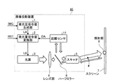
図1は、本発明の実施の形態1に係る画像投影装置の構成例を示すブロック図である。図1に示す実施の形態1の画像投影装置85は、画像光をスクリーン7に投影させる装置であり、光路上(例えばスクリーン7上)で不具合が発生した場合に、不具合(意図しない不適切な光)を速やかに検知して画像の表示を停止させる。画像投影装置85は、発光量指令値生成部1、発光量指令値変換部2、光源3、レンズ部4、スキャナ(第1の光走査部)5、ハーフミラー6、距離センサ(距離測定部)11を含んで構成されている。
FIG. 1 is a block diagram showing a configuration example of an image projection apparatus according to
発光量指令値生成部1は、映像信号の出力装置(図示せず)から送られてくる映像信号IMGを外部から入力(受信)し、外部入力した映像信号IMGに基づいて基準発光量指令値LAを生成する。基準発光量指令値LAは、発光量指令値変換部2で生成される発光量指令値LBの基準値(変換前データ)である。光路上で不具合が発生していない場合には、例えば基準発光量指令値LAが、そのまま光源3を駆動させるための指令値(電圧指令値または電流指令値)としての発光量指令値LBとなる。換言すると、基準発光量指令値LAは、映像信号IMGに応じて生成される指令値(光源3への発光量の指令値)であり、発光量指令値LBの生成に用いる指令基準値である。また、発光量指令値LBは、光路上での不具合に応じて基準発光量指令値LAを補正した指令値である。発光量指令値生成部1は、生成した基準発光量指令値LAを発光量指令値変換部2に出力する。
The light emission amount command
発光量指令値変換部2は、距離センサ11から出力される距離値DAを入力(受信)するとともに、画像投影装置85の外部から送られてくるリセット信号RSTを入力(受信)する。発光量指令値変換部2は、距離値DAおよびリセット信号RSTに基づいて、光路上の不具合を判定し、基準発光量指令値LAを不具合の有無に応じた発光量指令値LBに変換する。発光量指令値変換部2は、基準発光量指令値LAを、距離値DAに応じた値に変換することによって発光量指令値LBを生成する。発光量指令値変換部2は、生成した発光量指令値LBを光源3に出力する。
The light emission amount command
光源3は、出射する光の光量を発光量指令値LBに従って変調し、光量を変調した光をレンズ部4に出射する。換言すると、光源3は、出射する光量(発光光量)が発光量指令値LBによって制御される。
The light source 3 modulates the light amount of the emitted light according to the light emission amount command value LB, and emits the light whose light amount has been modulated to the
レンズ部4は、光源3から出射された光をスキャナ5に適した形状に整形し、ハーフミラー6に出射する。ハーフミラー6は、光源3から出射されてレンズ部4を介して送られてきた光と、距離センサ11から出射された光と、を重ね合わせて、スキャナ5に出射する。また、ハーフミラー6は、スキャナ5を介して戻ってくるスクリーン7からの反射光を距離センサ11に出射する。
The
スキャナ5は、ハーフミラー6から出射された光を、画像投影装置85の外側に設置されたスクリーン7に対して2次元に走査投影する。スクリーン7は、スキャナ5から出射された光を受光して画像(映像)を表示する。
The scanner 5 two-dimensionally scans and projects the light emitted from the half mirror 6 onto the
距離センサ11は、ハーフミラー6に対して光(距離測定用の光)を出射するとともに、スクリーン7からの距離測定用の光の反射光を、ハーフミラー6を介して受光する。距離センサ11は、例えば、スキャナ5から出射されスクリーン7上の照射部8にて反射または透過された光の一部を受光する。
The
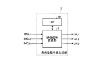
図2は、発光量指令値生成部の構成例を示すブロック図である。発光量指令値生成部1は、映像信号変換部9とルックアップテーブル(以下、LUTと呼ぶ)10とを含んで構成されている。ここでは、発光量指令値生成部1に入力される映像信号IMGがR(赤色)、G(緑色)、B(青色)の色毎に分かれており、それぞれIMG_r、IMG_g、IMG_bである場合について説明する。
FIG. 2 is a block diagram illustrating a configuration example of the light emission amount command value generation unit. The light emission amount command
発光量指令値生成部1に入力される映像信号IMG_r、IMG_g、IMG_bは、それぞれ映像信号変換部9に入力される。映像信号変換部9は、LUT10に予め与えておいた関係(変換式)に従って、映像信号IMG_r、IMG_g、IMG_bを、それぞれ基準発光量指令値LA_r,LA_g,LA_bに変換して出力する。ここでの基準発光量指令値LA_r,LA_g,LA_bは、光源3が電圧駆動方式の場合は光源3への電圧の指令値であり、光源3が電流駆動方式の場合は光源3への電流の指令値である。以下では、光源3が電流駆動方式の場合を例にして説明を行う。
Video signals IMG_r, IMG_g, and IMG_b that are input to the light emission amount command
図3は、LUTに予め設定しておく映像信号IMGと基準発光量指令値LAとの関係の一例を示す図である。図3のグラフでは、映像信号IMGから基準発光量指令値LAへの変換関係を示している。図3の横軸は、映像信号変換部9に入力される映像信号IMGの階調レベル(IMG_x)であり、縦軸は映像信号IMGに対応する基準発光量指令値LA(LA_x)である。 FIG. 3 is a diagram illustrating an example of the relationship between the video signal IMG set in advance in the LUT and the reference light emission amount command value LA. The graph of FIG. 3 shows the conversion relationship from the video signal IMG to the reference light emission amount command value LA. The horizontal axis in FIG. 3 is the gradation level (IMG_x) of the video signal IMG input to the video signal converter 9, and the vertical axis is the reference light emission amount command value LA (LA_x) corresponding to the video signal IMG.
Icは、光源3の仕様によって決まるカットオフ電流値であり、入力する映像信号IMGの階調レベルが0である場合、LA=Ic_xとなる。そして、映像信号IMGの階調レベルが大きくなるにつれ、基準発光量指令値LAも徐々に大きくなる。なお、ここでは説明を簡単にするために、映像信号IMGと基準発光量指令値LAの関係が線形である場合を示しているが、両者の関係は光源3の特性や使用環境によって変化するものであり、線形関係に限ったものではない。 Ic is a cut-off current value determined by the specifications of the light source 3, and LA = Ic_x when the gradation level of the input video signal IMG is 0. As the gradation level of the video signal IMG increases, the reference light emission amount command value LA also gradually increases. Here, for simplicity of explanation, the case where the relationship between the video signal IMG and the reference light emission amount command value LA is linear is shown, but the relationship between the two changes depending on the characteristics of the light source 3 and the use environment. It is not limited to a linear relationship.
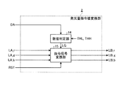
図4は、発光量指令値変換部の構成例を示すブロック図である。発光量指令値変換部2は、数値判定部14、指令信号変換部15を含んで構成されている。数値判定部14は、距離センサ11から出力された距離値DAと、予め設定しておいた閾値(後述の下限閾値THL、上限閾値THH)と、を比較して大小関係を判定し、判定結果に基づいて発光量変換ゲイン値LGを生成し、指令信号変換部15に出力する。発光量変換ゲイン値LGは、光路上に不具合が発生しているか否かを示す情報である。発光量変換ゲイン値LGは、例えば光路上に不具合が発生している場合に「0」を示し、不具合が発生していない場合に「1」を示す。
FIG. 4 is a block diagram illustrating a configuration example of the light emission amount command value conversion unit. The light emission amount command
閾値は、光路上に不具合が発生しているか否かの判定基準となる値であり、距離値DAと比較される値である。数値判定部14は、距離値DAが下限閾値THLより小さい場合に、発光量変換ゲイン値LGとして光路上の不具合発生を示す「0」を出力する。また、数値判定部14は、距離値DAが上限閾値THH以上の場合に、発光量変換ゲイン値LGとして光路上の不具合発生を示す「0」を出力する。また、数値判定部14は、距離値DAが下限閾値THL以上で且つ上限閾値より小さい場合に、発光量変換ゲイン値LGとして光路上の正常状態を示す「1」を出力する。 The threshold value is a value that serves as a criterion for determining whether or not a defect has occurred on the optical path, and is a value that is compared with the distance value DA. When the distance value DA is smaller than the lower limit threshold value THL, the numerical value determination unit 14 outputs “0” indicating a failure occurrence on the optical path as the light emission amount conversion gain value LG. In addition, the numerical value determination unit 14 outputs “0” indicating the occurrence of a problem on the optical path as the light emission amount conversion gain value LG when the distance value DA is equal to or greater than the upper limit threshold THH. Further, the numerical value determination unit 14 outputs “1” indicating a normal state on the optical path as the light emission amount conversion gain value LG when the distance value DA is equal to or larger than the lower limit threshold THL and smaller than the upper limit threshold.
指令信号変換部15は、発光量変換ゲイン値LGおよび画像投影装置85の外部から入力するリセット信号RSTに基づいて、基準発光量指令値LA_r,LA_g,LA_bをそれぞれ発光量指令値LB_r,LB_g,LB_bに変換し光源3に出力する。リセット信号RSTは、光源3の出射停止を解除させるための信号(解除指示)である。リセット信号RSTは、例えば、光路上が正常な状態であることが確認された場合に、使用者やマイクロコンピュータによって外部入力される。
Based on the light emission amount conversion gain value LG and the reset signal RST input from the outside of the
図5は、数値判定部での入力信号と出力信号の関係の一例を説明するための図である。数値判定部14への入力信号が距離値DAであり、数値判定部14からの出力信号が発光量変換ゲイン値LGである。図5に示すグラフは、横軸が距離値DAであり、縦軸が数値判定部14から出力する発光量変換ゲイン値LGである。発光量変換ゲイン値LGは、距離値DAが下限閾値THLより小さい場合や上限閾値THH以上の場合に「0」とする。また、発光量変換ゲイン値LGは、距離値DAが下限閾値THL以上で且つ上限閾値THHより小さい場合に「1」とする。 FIG. 5 is a diagram for explaining an example of the relationship between the input signal and the output signal in the numerical value determination unit. An input signal to the numerical value determination unit 14 is a distance value DA, and an output signal from the numerical value determination unit 14 is a light emission amount conversion gain value LG. In the graph shown in FIG. 5, the horizontal axis is the distance value DA, and the vertical axis is the light emission amount conversion gain value LG output from the numerical value determination unit 14. The light emission amount conversion gain value LG is set to “0” when the distance value DA is smaller than the lower limit threshold THL or greater than the upper limit threshold THH. The light emission amount conversion gain value LG is set to “1” when the distance value DA is not less than the lower limit threshold THL and smaller than the upper limit threshold THH.
下限閾値THLは、例えば距離センサ11からスキャナ5までの光学距離をMとし、スキャナ5からスクリーン7までの距離(光路上の距離)をLとすると、THL=M+Lである。また、上限閾値THHは、スキャナ5からの光の最大出射角をθMAXとすると、THH=M+L/cosθMAXである。
The lower limit threshold THL is, for example, THL = M + L where M is the optical distance from the
背面投射型の画像表示装置のように、スキャナ5からスクリーン7までの距離Lが、画像表示装置の設置状態によって変化しないのであれば、下限閾値THLや上限閾値THHを予め設定しておいてもよい。また、前面投射型の画像表示装置のように、スキャナ5からスクリーン7までの距離Lを、スクリーン7の設置の状態ごとに変化させたい場合は、設置の都度キャリブレーションを行い、設置の都度下限閾値THLおよび上限閾値THHを設定しなおしてもよい。
If the distance L from the scanner 5 to the
具体的には、画像投影装置85の立ち上げシーケンスにおいて、光源3から光を出射する前に、距離センサ11およびスキャナ5を駆動して距離センサ11からスクリーン7までの光路上の距離Lを計測する。画像投影装置85を設置する都度、キャリブレーションを行うことで、スキャナ5とスクリーン7の距離Lを自由に設定することが可能になる。
Specifically, in the startup sequence of the
発光量指令値生成部1から出力された基準発光量指令値LA_r,LA_g,LA_b、数値判定部14から出力された発光量変換ゲイン値LG、および画像投影装置85の外部から入力されたリセット信号RSTは、それぞれ指令信号変換部15に入力される。
The reference light emission amount command values LA_r, LA_g, LA_b output from the light emission amount command
図6は、指令信号変換部の構成例を示すブロック図である。指令信号変換部15は、ゼロゲイン保持部16と、乗算部17を含んで構成されている。数値判定部14から出力された発光量変換ゲイン値LGと、画像投影装置85の外部から入力されたリセット信号RSTは、ゼロゲイン保持部16に入力される。ゼロゲイン保持部16は、入力された発光量変換ゲイン値LGおよびリセット信号RSTに基づいて、発光量変換ゲインリセット値RGを生成し、乗算部17に出力する。発光量変換ゲインリセット値RGは、光源3から光を出射させるか停止させるかを指示する情報である。ゼロゲイン保持部16は、例えば光源3から光を出射させる場合には、発光量変換ゲインリセット値RGとして「1」を出力し、光源3からの光を停止させる場合には、発光量変換ゲインリセット値RGとして「0」を出力する。
FIG. 6 is a block diagram illustrating a configuration example of the command signal conversion unit. The command
乗算部17は、発光量変換ゲインリセット値RGに基づいて、発光量指令値生成部1から出力された基準発光量指令値LA_r,LA_g,LA_bを発光量指令値LB_r,LB_g,LB_bに変換して光源3に出力する。
Based on the light emission amount conversion gain reset value RG, the multiplication unit 17 converts the reference light emission amount command values LA_r, LA_g, LA_b output from the light emission amount command
図7は、ゼロゲイン保持部の動作を説明するための図である。図7では、クロック信号(Clock)、発光量変換ゲイン値LG、発光量変換ゲインリセット値RG、リセット信号RSTの各出力タイミングチャートを示している。ここでは、数値判定部14から出力される発光量変換ゲイン値LGが「0」または「1」の2値の場合を例として説明を行う。 FIG. 7 is a diagram for explaining the operation of the zero gain holding unit. FIG. 7 shows output timing charts of the clock signal (Clock), the light emission amount conversion gain value LG, the light emission amount conversion gain reset value RG, and the reset signal RST. Here, the case where the light emission amount conversion gain value LG output from the numerical value determination unit 14 is a binary value of “0” or “1” will be described as an example.
Clockは、映像信号の画素クロックである。発光量指令値変換部2は、画素クロックに従って動作する。数値判定部14から出力された発光量変換ゲイン値LGが「1」の場合、発光量変換ゲインリセット値RGとしては「1」が出力される。発光量変換ゲイン値LGが「1」から「0」に変化すると、発光量変換ゲインリセット値RGとして「0」が出力される。この後、発光量変換ゲイン値LGが「0」から「1」に変化しても、発光量変換ゲインリセット値RGとしては「0」が出力され続ける。
Clock is a pixel clock of the video signal. The light emission amount command
発光量変換ゲインリセット値RGが「0」である場合に、数値判定部14から出力された発光量変換ゲイン値LGが「1」であり、かつ画像投影装置85の外部から入力されるリセット信号RSTが「1」(アクティブ)であれば、発光量変換ゲインリセット値RGは「1」に変化する。言い換えれば、一旦、発光量変換ゲインリセット値RGが「0」になると、アクティブなリセット信号RSTが入力されない限り、発光量変換ゲインリセット値RGとしては「0」が出力され続ける。
When the light emission amount conversion gain reset value RG is “0”, the light emission amount conversion gain value LG output from the numerical value determination unit 14 is “1”, and the reset signal is input from the outside of the
ゼロゲイン保持部16から出力された発光量変換ゲインリセット値RGと、発光量指令値生成部1から出力された基準発光量指令値LA_r,LA_g,LA_bは、乗算部17に入力される。乗算部17では、入力した基準発光量指令値LA_r,LA_g,LA_bに対して、発光量変換ゲインリセット値RGを乗算することで、発光量指令値LB_r,LB_g,LB_bを生成し出力する。このとき、発光量変換ゲインリセット値RGが「0」であれば、発光量指令値LB_r,LB_g,LB_bは全て「0」になり、光源3は光の出射を停止する。一方、発光量変換ゲインリセット値RGが「1」であれば、光源3は発光量指令値LB_r,LB_g,LB_bに応じた光量の光を出射する。
The light emission amount conversion gain reset value RG output from the zero
図8は、光源の構成例を示すブロック図である。光源3は、電源部18、電流変調部19a,19b,19c、LD_r20、LD_g21、LD_bを含んで構成されている。 FIG. 8 is a block diagram illustrating a configuration example of a light source. The light source 3 includes a power supply unit 18, current modulation units 19a, 19b, and 19c, LD_r20, LD_g21, and LD_b.
電源部18は、光源3を光らせるためのエネルギー(電流I_r,I_g,I_b)を電流変調部19a,19b,19cに供給する。電流変調部19a,19b,19cは、例えば定電流回路を備えて構成されている。電流変調部19a,19b,19cは、発光量指令値変換部2から出力された、発光量指令値LB_r,LB_g,LB_bに基づいて、LD_r20、LD_g21、LD_b22に供給する電流I_r,I_g,I_bを変調し、それぞれLD_r20、LD_g21、LD_b22に出力する。
The power supply unit 18 supplies energy (currents I_r, I_g, I_b) for causing the light source 3 to emit light to the current modulation units 19a, 19b, 19c. The current modulators 19a, 19b, and 19c are configured with a constant current circuit, for example. Based on the light emission amount command values LB_r, LB_g, and LB_b output from the light emission amount command
LD_r20、LD_g21、LD_b22は、それぞれ波長の異なる可視光領域の光を出射するレーザダイオード(以下、LDとよぶ)である。具体的には、LD_r20は赤色、LD_g21は緑色、LD_b22は青色をそれぞれ出射する。なお、LD_g21は、例えば赤外発光のレーザを半波長板で波長変換したものを用いてもよい。 LD_r20, LD_g21, and LD_b22 are laser diodes (hereinafter referred to as LDs) that emit light in the visible light region having different wavelengths. Specifically, LD_r20 emits red, LD_g21 emits green, and LD_b22 emits blue. The LD_g21 may be, for example, an infrared laser that has been wavelength-converted with a half-wave plate.
図9は、LDのI−P特性を説明するための図である。図9は、横軸が電流量I_xであり、縦軸が光出力P_xである。LD_r20、LD_g21、LD_b22からの光出力P_xを、それぞれ光出力P_r,P_g,P_bとする。図9では、電流量I_x(xはr、g、bのいずれか)に対する、光出力P_x(xはr、g、bのいずれか)の大きさを示している。光出力P_xは、カットオフ電流Ic_x以上の電流量I_xで発光を開始し、電流量I_xが増加するに従って、光出力P_xも増加する。 FIG. 9 is a diagram for explaining the IP characteristic of the LD. In FIG. 9, the horizontal axis represents the current amount I_x, and the vertical axis represents the optical output P_x. The optical outputs P_x from the LD_r20, LD_g21, and LD_b22 are set as optical outputs P_r, P_g, and P_b, respectively. FIG. 9 shows the magnitude of the optical output P_x (x is any of r, g, or b) with respect to the current amount I_x (x is any of r, g, or b). The light output P_x starts to emit light with a current amount I_x equal to or greater than the cut-off current Ic_x, and the light output P_x increases as the current amount I_x increases.
画像投影装置85のスキャナ5が、DMD(登録商標)、HTPS、LCOSといった空間変調素子を利用しない場合、各画素の階調は光源3から出射する光量をアナログ制御(以下、光源変調とよぶ)して生成する必要がある。このとき、光源変調の周波数は、入力する映像信号IMGの画素クロック(ドットクロック)相当の速さが求められる。光源変調の周波数特性を向上させるためには、変調振幅を小さくしておくほうが良く、入力する映像信号IMGのレベルが0の場合でも、電流量I_xを0にせず、カットオフ電流Ic_xにしておくことが望ましい。
When the scanner 5 of the
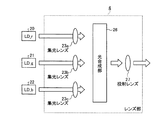
光源3のLD_r20、LD_g21、LD_b22から出射された光は、レンズ部4に入射する。図10は、レンズ部の構成例を示す図である。レンズ部4は、集光レンズ23a,23b,23c、光合成部26、投射レンズ27を含んで構成されている。
Light emitted from the LD_r20, LD_g21, and LD_b22 of the light source 3 enters the
LD_r20から出射された光は、集光レンズ23aを介して光合成部26に入射する。また、LD_g21から出射された光は、集光レンズ23bを介して光合成部26に入射し、LD_b22から出射された光は、集光レンズ23cを介して光合成部26に入射する。光合成部26では、入射してくる波長の異なる3つの光を合成し、投射レンズ27に出射する。投射レンズ27は、光合成部26から出射された光を集め、スキャナ5に出射する。
The light emitted from the
図11は、光合成部の構成例を示す図である。光合成部26は、ミラー31、ハーフミラー32,33を有している。集光レンズ23aから出射された赤色光は、ミラー31で光軸を曲げられた後、ハーフミラー32にて、集光レンズ23cから出射された青色光と重ね合わされる。ハーフミラー32で生成された、赤と青の混合光はハーフミラー33によって、集光レンズ23bから出射された緑色光と重ね合わされて投射レンズ27に出射される。なお、光の合成する順番は図12に示した順番に限らず、何れの順番で合成してもよい。
FIG. 11 is a diagram illustrating a configuration example of the light combining unit. The
距離センサ11は、対象物に対して光を出射してから、対象物からの反射光を受光部で受光するまでの時間に基づいて対象物までの距離を計測するタイムオブフライト方式の距離センサである。距離センサ11を用いた光学的距離測定方法では、距離センサ11から出射する光は不可視光(不可視光レーザなど)が望ましい。距離センサ11から出射する光は、赤外のレーザ光などであり、例えば波長が1400nm〜2600nmまでの、いわゆるアイセーフレーザであることが望ましい。なお、距離センサ11から出射する光の波長(波長領域)は、光源3から出射される光の波長(波長領域)と異なる波長であれば可視光であってもよい。
The
距離センサ11から出射された光はハーフミラー6に入射する。ハーフミラー6は、LD_r20、LD_g21、LD_b22から出射されて重ね合わされた後にレンズ部4を介して送られてくる光と、距離センサ11から出射された赤外光と、を重ね合わせてスキャナ5に出射する。また、スクリーン7で反射された光の一部はスキャナ5を介してハーフミラー6に戻る。ハーフミラー6は、スクリーン7で反射された光の一部を、距離センサ11に出射する。
The light emitted from the
スキャナ5は、レンズ部4から出射された光を、スクリーン7に対して2次元にスキャン(走査投影)する。スキャナ5は、プリンタや露光装置などに用いられているスキャナと同様の構造を有している。スキャナ5としては、例えば、特開2006−116696号公報(段落0009〜0010、図1)などで開示されているような、MEMSを利用した2軸スキャンの技術を用いて構成しておく。
The scanner 5 scans (scans and projects) two-dimensionally the light emitted from the
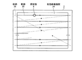
図12は、実施の形態1に係るスキャナの動作の一例を説明するための図であり、スキャナから出射される光の軌跡を示している。図12では、スクリーン7を映像の観察者側がら見た場合の一例を示している。
FIG. 12 is a diagram for explaining an example of the operation of the scanner according to the first embodiment, and shows a trajectory of light emitted from the scanner. FIG. 12 shows an example when the
図12中の破線は、映像のブランキング期間におけるスキャナ5のスキャン軌跡36を示したものである。また、実線は、有効映像期間34におけるスキャナ5のスキャン軌跡35を示したものであり、照射部8が移動する軌跡でもある。照射部8は、スキャナ5によるスキャン位置と同じ位置になるよう、スキャン位置に従ってスキャン軌跡35上を移動する。
The broken line in FIG. 12 shows the
有効映像期間34は、表示対象となる有効な映像をスクリーン7にスキャンする期間である。有効映像期間34は、映像の表示領域であり、有効映像期間34にスキャン軌跡35でスキャンされた映像がスクリーン7に映し出される。映像のブランキング期間は、表示対象とならない無効な映像(ブランク)をスクリーン7にスキャンする期間であり、この間にスキャン軌跡36でスキャンされた映像はスクリーン7に映像が映し出されない。
The effective video period 34 is a period during which an effective video to be displayed is scanned on the
スキャナ5のスキャン軌跡35,36は、一般的な映像信号フォーマットに従って、スクリーン7の画面左上から開始され、上のラインから下のラインに向けて順次スキャンされ、かつ各ラインをスキャンする際には、各ラインを左から右に向けてスキャンされる。そして、最終ライン(最下段のライン)のスキャンが終了すると、スキャナ5のスキャン軌跡36は、左上のスタート位置に戻る。
The scanning trajectories 35 and 36 of the scanner 5 are started from the upper left of the
図13は、実施の形態1に係るスキャナの動作の別の例を説明するための図であり、スキャナから出射される光の軌跡の別の例を示している。図12のスキャン軌跡35,36と異なる点は、奇数番目のラインである奇数ラインは、左から右にスキャンされ、偶数番目のラインである偶数ラインは、右から左にスキャンされる点である。このスキャン方式の利点は、スキャナの駆動周波数を図12に示した方式の半分にすることができる点である。
FIG. 13 is a diagram for explaining another example of the operation of the scanner according to the first embodiment, and shows another example of the locus of light emitted from the scanner. 12 differs from the
また、最終ラインのスキャン終了後に、スクリーン7の画面左上に戻るのでなく、左上から右下への軌跡を逆に辿ってもよい。この場合、スキャナ5のスキャン軌跡36を右下から左上に戻す時間が不要になるので、スキャナ5の駆動周波数を低くすることが可能となる。
Further, after the last line is scanned, the trajectory from the upper left to the lower right may be traced in reverse instead of returning to the upper left of the
図14は、前面投射型の画像表示装置の配置例を示す図である。図14では、スキャナ5から出射された光を、スクリーン7の照射部8側から見る場合の画像表示装置90の断面図を示している。前面投射型の画像表示装置90は、画像投影装置85とスクリーン7とを備えている。
FIG. 14 is a diagram illustrating an arrangement example of a front projection type image display device. FIG. 14 shows a cross-sectional view of the
前面投射型の画像表示装置90では、画像投影装置85内のスキャナ5からスクリーン7に投射された光が、スクリーン7上で適度に散乱され、反射散乱光が観察者40に観察される。このとき、光路上の不具合として、例えばスクリーン7に異常がある場合や、画像投影装置85からスクリーン7、またはスクリーン7から観察者40の間に障害がある場合、観察者40は適正に画像を観察できない。
In the front projection type
例えば、スクリーン7に孔が開いている場合、画像投影装置85内のスキャナ5から出射された光は、スクリーン7の孔の開いている箇所では拡散反射されることはない。このため、観察者40は、スクリーン7の背面から差込む外光を観察することとなる。
For example, when a hole is opened in the
また、画像投影装置85からスクリーン7までの間の空間は、外部と遮蔽されていないので、例えば光路上に障害物が侵入した場合、スクリーン7上には影が出現する。さらに、障害物は、画像投影装置85内のスキャナ5から出射され光を予期せぬ方向へ反射するので、観察者40の瞳孔に直接反射光が入射してしまう場合がある。これらは全て観察者40にとって不快な映像として観察されることとなる。
In addition, since the space between the
図15は、背面投射型の画像表示装置の配置例を示す図である。図15では、スキャナ5から出射された光を、観察者40がスクリーン7越しに見る場合の画像表示装置91の断面図を示している。例えば、背面投射型の画像表示装置91は、画像投影装置85と、スクリーン7と、筐体24と、を含んで構成されている。画像投影装置85内のスキャナ5から出射された光は、スクリーン7を透過することで適度に拡散され、拡散透過光が観察者40に観察される。
FIG. 15 is a diagram illustrating an arrangement example of a rear projection type image display device. FIG. 15 shows a cross-sectional view of the
画像表示装置91は、図14に示した画像表示装置90と異なり、画像投影装置85が筐体24内に収められている。画像表示装置91の場合、画像投影装置85内の光源3にLDを用いることで、レーザの優れた収束性により、他種光源を用いた場合と比較して投射光学系の小型化が可能になる。また、光源3にLDを用いることで、スクリーン7上の照射部8でのビームスポット径を小径化することが可能となるので、解像感が向上する。
Unlike the
また、画像表示装置91は、画像投影装置85が筐体24内に収められているので、画像投影装置85内のスキャナ5から出射された光がスクリーン7に入射するまでに、障害物が侵入してくることはない。さらに、距離センサ11が外光に直接暴露されることがないので、光量検出時のノイズを低減できる。
In the
一方、スクリーン7に異常がある場合、特にスクリーン7に孔が開いていた場合、画像表示装置91では、孔の位置によっては、スキャナ5から出射した光がスクリーン7で拡散されることなく直接観察者40の網膜に入るので、非常に不快な映像として認識されることとなる。特に、光源にLDを用いる場合、たとえパワーの低い光でも、直接光を網膜に長時間照射することは好ましくない。そこで、本実施の形態では、スキャナ5から出射した光が直接観察者40の網膜に入らないよう、光源3からの光の出射を停止させる。
On the other hand, when there is an abnormality in the
スクリーン7から距離センサ11に戻ってくる反射光には、距離センサ11が出射した赤外光以外にも、入力する映像信号IMGのレベルに従って変調された光源3から出射した光と外光が含まれる。このため、距離センサ11には、例えばバンドパスフィルタを設置し、バンドパスフィルタによって距離センサ11に戻ってくる光を濾波することが望ましい。
The reflected light returning from the
図16は、バンドパスフィルタの透過率曲線の例を示す図である。図16では、距離センサ11に戻る光を濾波するために用いるバンドパスフィルタの透過率曲線の一例を示している。図中の破線は、LD_r20、LD_g21、LD_b22および距離センサ11から出射される光のスペクトルである。光源3のLD_r20、LD_g21、LD_b22から出射される光の波長は、それぞれLD_r20は640nm付近、LD_g21は530nm付近、LD_b22は450nm付近である。
FIG. 16 is a diagram illustrating an example of a transmittance curve of a bandpass filter. FIG. 16 shows an example of a transmittance curve of a band-pass filter used for filtering light returning to the
バンドパスフィルタの透過率曲線L3は、光源3から出射される可視光領域の光は透過させることなく、距離センサ11から出射される光の波長(ここでは距離センサ11から出射される光が、1450nm付近である場合を示している)を透過中心波長とする透過率曲線になっている。
The transmittance curve L3 of the bandpass filter does not transmit the light in the visible light region emitted from the light source 3, but the wavelength of the light emitted from the distance sensor 11 (here, the light emitted from the
バンドパスフィルタは、距離センサ11に入射する光として、距離センサ11から出射されてスクリーン7で反射された光を精度良く検出するために用いられる。言い換えれば、バンドパスフィルタは、距離センサ11以外からの光(光源3からの光や外光)の影響を低減するために用いている。このため、バンドパスフィルタは、距離センサ11から出射される波長の光を出来るだけ透過させ、距離センサ11から出射された光以外の光を出来るだけ遮蔽することが望ましい。
The bandpass filter is used to accurately detect light emitted from the
図16に示した透過率曲線L3では、透過領域の半値幅を10nm程度で示しているが、距離センサ11の受光感度やバンドパスフィルタの製造コストが許す限り、透過領域の半値幅は少しでも狭いほうが良い。透過領域の半値幅を狭くできるのは、光源3にスペクトルが急峻なLDを用いていることの利点でもある。 In the transmittance curve L3 shown in FIG. 16, the FWHM of the transmissive region is indicated by about 10 nm. Narrower is better. The fact that the FWHM of the transmission region can be narrowed is also an advantage of using an LD having a sharp spectrum for the light source 3.
バンドパスフィルタで濾波されたスクリーン7からの反射光を受光した距離センサ11は、光を出射してから、反射光を受光するまでの時間に基づいて距離値DAを生成し、発光量指令値変換部2に出力する。
The
図17は、スキャナと光量センサの配置例を示す斜視図である。スキャナ5を用いた投影方法では、スキャナ5をスクリーン7の中心軸25上に配置する場合が、スキャナ5の振幅量を最も少なくでき、かつスキャンにより発生するスクリーン7上の歪も少なくなる。実際には、他機器との干渉や、例えば前面投射型の場合は観察者との交錯等の問題があるので、スキャナ5は、中心軸25に対して、上下方向にオフセットして配置される場合が多い。本実施の形態では、スキャナ5をスクリーン7の中心軸25上に配置してもよいし、スキャナ5を中心軸25に対して上下方向にオフセットして配置してもよい。
FIG. 17 is a perspective view illustrating an arrangement example of the scanner and the light amount sensor. In the projection method using the scanner 5, when the scanner 5 is arranged on the
スキャナ5は、スクリーン7のスクリーン面に正対して配置されるので、光の出射角=スクリーン入射角となる。したがって、スクリーン7へは、スキャナ5からの光の出射角に応じた角度で光が入射する。スキャナ5は、スクリーン7上の種々の位置に光を出射するので、照射部8毎に照射部8の位置に応じた光の出射角でスキャナ5から光が出射される。例えば、スキャナ5から光の出射角θ1で光が出射されると、スクリーン7へはスクリーン入射角φ1(θ1=φ1)で光が入射する。また、スキャナ5から光の出射角θ2で光が出射されると、スクリーン7へはスクリーン入射角φ2(θ2=φ2)で光が入射する。
Since the scanner 5 is arranged facing the screen surface of the
図18は、スキャナからの光の出射角と距離センサが出力する距離値の関係例を示す図である。図18の横軸はスキャナからの出射角θであり、縦軸は距離センサ11が出力する距離値DAである。
FIG. 18 is a diagram illustrating an example of the relationship between the light emission angle from the scanner and the distance value output by the distance sensor. The horizontal axis in FIG. 18 is the exit angle θ from the scanner, and the vertical axis is the distance value DA output from the
距離センサ11からスクリーン7上の照射部8までの距離は、スキャナ5からの出射角θに応じて変化する。特にスキャナ5がスクリーン7の中心軸25上にて、スクリーン7に正対して設置されている場合、距離センサ11が出力する距離値DAは、スキャナ5からの光の出射角θが大きくなるに従って大きくなる。
The distance from the
距離センサ11のサンプリング周期tは、例えば、入力する映像信号IMGの画素クロックの周期CLKと同等であることが望ましい。距離センサ11のサンプリング周期tが、入力する映像信号IMGの画素クロックの周期CLKと同等であれば、1画素幅の微小なスクリーン7上の孔も検出可能になる。
For example, the sampling period t of the
画像投影装置85は以上のように構成されているので、光路上に異常がある場合(例えばスクリーン7に孔が開いている場合)には、距離値DAが、予め定めておいた上限閾値THH以上の値をとることとなる。このため、発光量変換ゲイン値LGが0になり、その結果、光源3からの光の出射が停止する。また、映像投射装置85とスクリーン7の間に障害物が侵入した場合、距離値DAが予め定めておいた下限閾値THLより小さな値をとることとなる。このため、発光量変換ゲイン値LGが0になり、その結果、光源3からの光の出射が停止する。
Since the
さらに、発光量変換ゲイン値LGが一旦0になると、アクティブなリセット信号RSTが入力されない限り発光量変換ゲイン値LGが再び1になることが無いので、観察者が不快な映像を見続けることはない。 Further, once the light emission amount conversion gain value LG becomes 0, the light emission amount conversion gain value LG does not become 1 again unless an active reset signal RST is input, and thus the observer cannot continue to view an unpleasant image. Absent.
このように、実施の形態1によれば、光路上での不具合の発生に起因する意図しない光(不適切な光)(スクリーン7で拡散されなかった光など)を距離値DAに基づいて速やかに検知して光源3からの発光を停止させるので、スクリーン7からの意図しない光の出射を停止することが可能となる。したがって、光路上に不具合がある場合、光源3から光が出射されることはなく、スクリーン7で拡散されなかった光や光路上の障害物の影、また障害物により予期せぬ方向へ反射された光を含む不快な映像を見続けることはない。
As described above, according to the first embodiment, unintended light (inappropriate light) (such as light that has not been diffused by the screen 7) due to the occurrence of a defect on the optical path is promptly generated based on the distance value DA. Therefore, the emission of light from the light source 3 is stopped, so that it is possible to stop the unintentional emission of light from the
実施の形態2.
つぎに、図19および図20を用いてこの発明の実施の形態2について説明する。実施の形態2では、画像投影装置に2つのスキャナを配置しておき、一方のスキャナから距離測定用の光を照射し、他方のスキャナから映像表示量の光を照射する。距離測定用の光は、この後に映像表示量の光が照射される位置に照射しておき、この位置での距離値DAを算出し、算出した距離値DAに応じた映像表示用の光を照射する。
Next, a second embodiment of the present invention will be described with reference to FIGS. In the second embodiment, two scanners are arranged in the image projection apparatus, light for distance measurement is emitted from one scanner, and image display light is emitted from the other scanner. The distance measurement light is irradiated to the position where the image display amount of light is irradiated after that, the distance value DA at this position is calculated, and the image display light corresponding to the calculated distance value DA is used. Irradiate.
図19は、実施の形態2に係る画像投影装置の構成例を示すブロック図である。なお、図19の各構成要素のうち図1に示す実施の形態1の画像投影装置85と同一機能を達成する構成要素については同一番号を付しており、重複する説明は省略する。
FIG. 19 is a block diagram illustrating a configuration example of the image projection apparatus according to the second embodiment. Of the constituent elements in FIG. 19, constituent elements that achieve the same functions as those of the
実施の形態2に係る画像投影装置86が、図1に示す画像投影装置85と異なる点は、画像投影装置86が、ハーフミラー6を有していない点と、2つのスキャナ5a、5bを有している点などである。
The
発光量指令値生成部1は、入力した映像信号IMGに基づいて、基準発光量指令値LAを生成し、発光量指令値変換部2に出力する。発光量指令値変換部2は、距離センサ11から出力される距離値DAおよびリセット信号RSTに基づいて、基準発光量指令値LAを発光量指令値LBに変換し、光源3に出力する。
The light emission amount command
光源3は、出射する光の光量を発光量指令値LBに従って変調し、光量を変調した光をレンズ部4に出射する。レンズ部4は、光源3から出射された光をスキャナ5aに適した形状に整形し、スキャナ5aに出射する。
The light source 3 modulates the light amount of the emitted light according to the light emission amount command value LB, and emits the light whose light amount has been modulated to the
スキャナ(第1の光走査部)5aは、実施の形態1で説明したスキャナ5と同様の機能を有しており、同様の動作を行なう。具体的には、スキャナ5aは、レンズ部4から出射された光を、画像投影装置86の外側に設置されたスクリーン7に対して2次元に走査投影する。
The scanner (first optical scanning unit) 5a has the same function as the scanner 5 described in the first embodiment, and performs the same operation. Specifically, the scanner 5a scans and projects the light emitted from the
距離センサ11は、スキャナ5bに対して光を出射するとともに、スクリーン7からの反射光を、スキャナ(第2の光走査部)5bを介して受光する。距離センサ11は、スキャナ5bに光を出射してから、スクリーン7からの反射光を受光するまでの時間に基づいて距離値DAを生成し、発光量指令値変換部2に出力する。
The
スキャナ5bは、距離センサ11から出射された光を、スクリーン7上で、スキャナ5aに同期して2次元に走査投影する。また、スクリーン7からの反射光の一部を受光して距離センサ11に戻す。
The
スクリーン7は、スキャナ5aから出射された光を照射部8aで受光して画像(映像)を表示する。また、スクリーン7は、スキャナ5bから出射された光を照射部8bで反射して、スキャナ5bに送る。
The
本実施の形態では、スキャナ5a,5bをスクリーン7に対してほぼ同じ位置に配置しておき、これにより、スキャナ5aからスクリーン7までの光路と、スキャナ5bからスクリーン7までの光路とを略同じにしておく。さらに、スキャナ5aによる走査とスキャナ5bによる走査とを同期制御する。そして、スキャナ5bが光を照射する位置はをスキャナ5aが光を照射する位置よりも所定数の画素分だけ走査方向に手前の位置としておく。これにより、画像投影装置86は、スキャナ5aが光を照射する位置への発光量指令値LBを、予め距離センサ11が照射部8bでの距離を計測することによって導出しておく。
In the present embodiment, the
図20は、実施の形態2に係るスキャナの動作の一例を説明するための図であり、スキャナから出射される光の軌跡を示している。図20では、スクリーン7を映像の観察者側がら見た場合の一例を示している。
FIG. 20 is a diagram for explaining an example of the operation of the scanner according to the second embodiment, and shows a trajectory of light emitted from the scanner. FIG. 20 shows an example when the
図20中の破線は、映像のブランキング期間におけるスキャナ5のスキャン軌跡36を示したものである。また、実線は、有効映像期間34におけるスキャナ5のスキャン軌跡35を示したものであり、照射部8a,8bが移動する軌跡でもある。照射部8a,8bは、それぞれスキャナ5a,5bによるスキャン位置と同じ位置になるよう、スキャン位置に従ってスキャン軌跡35,36上を移動する。
The broken line in FIG. 20 shows the
ここで、照射部8aと照射部8bの位置関係について説明する。スキャナ5aは、距離センサ11が照射部8bでの距離を計測した結果に基づいて生成された発光量指令値LBでスクリーン7への光照射を行う。このため、スキャナ5bは、所定時間経過後にスキャナ5aが光を照射する位置(照射部8a)またはこの位置よりも走査方向で手前の位置を照射部8bとして光照射し、これにより距離センサ11は照射部8bでの距離値DAを生成しておく。ここでの所定時間は、画像投影装置86が光の照射制御に要する時間である。スキャナ5bは、例えばスキャナ5aが映像を表示させる位置の直前の位置を照射部8bとして光を照射しておく。
Here, the positional relationship between the
換言すると、スキャナ5b(距離センサ11)は、スクリーン7上の第1の光照射位置(照射部8b)に距離測定用の光を照射する。このとき、スキャナ5a(光源3)は、第1の光照射位置よりも走査方向に手前の照射部8aに映像表示用の光を照射する。この後、スキャナ5bは、走査方向に従って、次の照射位置に距離測定用の光を照射し、スキャナ5aは、走査方向に従って、次の照射位置に映像表示用の光を照射していく。発光量指令値変換部2では、第1の光照射位置で測定した距離に対する発光量指令値LBが生成され、これにより、スキャナ5aから発光量指令値LBで映像表示用の光が第2の光照射位置に照射される。この第2の光照射位置が、第1の光照射位置と同じ位置または第1の光照射位置よりも所定数の画素分だけ走査方向に手前の位置となるよう、画像投影装置86を調整しておく。
In other words, the
具体的には、スキャナ5aとスキャナ5bとは互いに同期し、スキャナ5bから出射された光の照射部8bは、スキャナ5aから出射された光の照射部8aよりもスキャン方向に少なくともFWだけ画素が進んだ位置を照射するように調整されている。そして、距離センサ11がスクリーン7上の任意の画素位置までの距離を計測して発光量指令値変換部2に距離値DAを出力する。発光量指令値変換部2は、距離値DAに基づいて、基準発光量指令値LAを発光量指令値LBに変換して光源3に出力する。
Specifically, the scanner 5a and the
光源3が発光量指令値LBに従って出射する光を制御するまでの時間をTとすると、入力した映像信号IMGの画素クロックの周期がCLKであるので、FW>T/CLKの関係を満たすようFWを設定しておく。換言すると、光源3が照射部8bでの距離に応じた光の照射制御に要する時間Tは、照射部8bでの距離が測定されてから、この照射部8bが照射部8aとなってスキャナ5aから光が照射されるまでの時間よりも短い時間となるようFWを設定しておく。なお、FWは、FW≧T/CLKであってもよい。これにより、距離センサ11が距離を計測した位置またはこの位置より少し手前の位置は、距離センサ11が計測した距離に応じた発光量指令値LBで光が照射されることとなる。
If the time until the light source 3 controls the light emitted in accordance with the light emission amount command value LB is T, the cycle of the pixel clock of the input video signal IMG is CLK, so that FW satisfies the relationship of FW> T / CLK. Is set in advance. In other words, the time T required for the light source 3 to control the irradiation of light according to the distance at the
したがって、画像投影装置86は、映像を表示させる位置での光路が不具合であるか否かを、映像を表示させる直前に判定して、光路上で不具合が発生している場合には、映像を表示する前に、映像を表示させるための光の照射を停止させることが可能となる。
Therefore, the
画像投影装置86は以上のように構成されているので、光源3からスクリーン7までの光路上のハーフミラー6の数を減らすことができる。これにより、簡易な構成で光源3から出射された光量を効率良くスクリーン7に照射することが可能になる。また、距離センサ11からスクリーン7までの光路上に余分なハーフミラーを設置する必要がなくなるので、距離センサ11から出射する光の光量を少なくすることが可能になる。
Since the
また、スキャナ5bから出射された光(例えばアイセーフレーザ)の照射部8bは、スキャナ5aから出射された光の照射部8aよりもスキャン方向に少なくともFWだけ画素が進んだ位置を走査投影するように調整されている。このため、光源3から出射された可視光が光路上の不具合の影響を受ける前に、光路上の不具合をリアルタイムで検知することができ、その結果、光源3からの光の出射を停止できる。したがって、スクリーン7で拡散されない光が直接観察者40の瞳孔に入射してしまう等の事故の発生を防止できる。
Further, the
このように、実施の形態2によれば、映像を表示させる位置での光路が不具合であるか否かを、映像を表示させる前に判定しているので、光路に不具合が発生している場合には、映像を表示する前に光源3から出射する光を停止することが可能となる。 As described above, according to the second embodiment, since it is determined whether or not the optical path at the position where the video is displayed is defective before the video is displayed, when the optical path is defective. It is possible to stop the light emitted from the light source 3 before displaying an image.
なお、上述した実施の形態1,2では、画像表示に用いる映像信号IMGがIMG_r、IMG_g、IMG_bの3色の信号から構成され、光源3が異なる波長の可視光を3つ出射する場合について説明したが、画像表示に用いる映像信号IMGは、2色以下の信号または4色以上の信号であってもよい。また、光源が出射する可視光は、1つの波長の可視光、異なる2つの波長の可視光、異なる4つ以上の波長の可視光であってもよい。 In the first and second embodiments described above, a case where the video signal IMG used for image display is composed of signals of three colors IMG_r, IMG_g, and IMG_b, and the light source 3 emits three visible lights having different wavelengths will be described. However, the video signal IMG used for image display may be a signal of two colors or less or a signal of four colors or more. The visible light emitted from the light source may be visible light having one wavelength, visible light having two different wavelengths, or visible light having four or more different wavelengths.
以上のように、本発明に係る画像投影装置および画像表示装置は、光源から出射した光のスキャナを用いたスクリーンへの投射に適している。 As described above, the image projection apparatus and the image display apparatus according to the present invention are suitable for projecting light emitted from a light source onto a screen using a scanner.
1 発光量指令値生成部
2 発光量指令値変換部
3 光源
4 レンズ部
5,5a,5b スキャナ
7 スクリーン
8,8a,8b 照射部
11 距離センサ
14 数値判定部
15 指令信号変換部
16 ゼロゲイン保持部
19a,19b,19c 電流変調部
85,86 画像投影装置
90,91 画像表示装置
L3 透過率曲線
DESCRIPTION OF
Claims (9)
前記光源から出射された光をスクリーン上に走査投影する第1の光走査部と、
前記光源から出射される光とは異なる波長領域の光を距離測定用の光として出射するとともに出射した光が前記スクリーンで反射されて戻ってくるまでの時間を計測することによって、自身から前記スクリーンまでの距離を測定する距離測定部と、
外部入力される映像信号に基づいて、前記発光量指令値の生成に用いる指令基準値を生成する発光量指令値生成部と、
前記指令基準値と前記距離測定部が測定した距離に基づいて前記発光量指令値を生成する発光量指令値変換部と、
を有し、
前記発光量指令値変換部は、前記距離測定部によって測定された距離と予め設定しておいた距離の許容範囲とを比較し、前記測定された距離が前記許容範囲外である場合に前記光源から光を停止させる発光量指令値を前記光源に出力するとともに、前記光源から光を停止させる発光量指令値を前記光源に出力した場合には、外部入力される出射停止の解除指示があるまで前記光源から光を停止させる発光量指令値を前記光源に出力し続けることを特徴とする画像投影装置。 A light source in which the amount of light emitted in the visible light region is controlled by a light emission amount command value that is a command value of the light emission amount;
A first light scanning unit that scans and projects light emitted from the light source onto a screen;
By emitting light in a wavelength region different from the light emitted from the light source as distance measuring light and measuring the time until the emitted light is reflected by the screen and returns, A distance measuring unit that measures the distance to
A light emission amount command value generation unit that generates a command reference value used to generate the light emission amount command value based on an externally input video signal;
A light emission amount command value conversion unit that generates the light emission amount command value based on the command reference value and the distance measured by the distance measurement unit;
Have
The light emission amount command value conversion unit compares the distance measured by the distance measurement unit with a preset allowable range of distance, and if the measured distance is outside the allowable range, the light source When a light emission amount command value for stopping light from the light source is output to the light source and a light emission amount command value for stopping light from the light source is output to the light source, there is an instruction to cancel the emission stop input from the outside. An image projection apparatus , wherein a light emission amount command value for stopping light from the light source is continuously output to the light source .
前記距離測定部から出射された距離測定用の光は、前記第2の光走査部を介して前記スクリーンに送られるとともに、前記スクリーンで反射された距離測定用の光は、前記第2の光走査部を介して前記距離測定部に送られることを特徴とする請求項1〜3のいずれか1つに記載の画像投影装置。 A second optical scanning unit that scans and projects distance measuring light emitted from the distance measuring unit in synchronization with the first optical scanning unit;
The distance measurement light emitted from the distance measurement unit is sent to the screen via the second optical scanning unit, and the distance measurement light reflected by the screen is the second light. The image projection apparatus according to claim 1, wherein the image projection apparatus is sent to the distance measurement unit via a scanning unit.
前記第2の光照射位置は、前記第1の光照射位置と同じ位置または前記第1の光照射位置よりも所定数の画素分だけ走査方向に手前の位置であることを特徴とする請求項5に記載の画像投影装置。 The light emission generated based on the distance measured at the first light irradiation position after the distance measurement light emitted from the distance measurement unit is irradiated to the first light irradiation position on the screen. The light from the light source irradiated to the screen with the amount command value is irradiated to a second light irradiation position on the screen,
The second light irradiation position is the same position as the first light irradiation position or a position in the scanning direction that is a predetermined number of pixels from the first light irradiation position. 5. The image projection apparatus according to 5 .
発光量の指令値である発光量指令値により、出射する可視光領域の光の発光光量が制御される光源と、
前記光源から出射された光を前記スクリーン上に走査投影する第1の光走査部と、
前記光源から出射される光とは異なる波長領域の光を距離測定用の光として出射するとともに出射した光が前記スクリーンで反射されて戻ってくるまでの時間を計測することによって、自身から前記スクリーンまでの距離を測定する距離測定部と、
外部入力される映像信号に基づいて、前記発光量指令値の生成に用いる指令基準値を生成する発光量指令値生成部と、
前記指令基準値と前記距離測定部が測定した距離に基づいて前記発光量指令値を生成する発光量指令値変換部と、
を有し、
前記発光量指令値変換部は、前記距離測定部によって測定された距離と予め設定しておいた距離の許容範囲とを比較し、前記測定された距離が前記許容範囲外である場合に前記光源から光を停止させる発光量指令値を前記光源に出力するとともに、前記光源から光を停止させる発光量指令値を前記光源に出力した場合には、外部入力される出射停止の解除指示があるまで前記光源から光を停止させる発光量指令値を前記光源に出力し続けることを特徴とする画像表示装置。 A screen to display an image;
A light source in which the amount of light emitted in the visible light region is controlled by a light emission amount command value that is a command value of the light emission amount;
A first optical scanning unit that scans and projects the light emitted from the light source onto the screen;
By emitting light in a wavelength region different from the light emitted from the light source as distance measuring light and measuring the time until the emitted light is reflected by the screen and returns, A distance measuring unit that measures the distance to
A light emission amount command value generation unit that generates a command reference value used to generate the light emission amount command value based on an externally input video signal;
A light emission amount command value conversion unit that generates the light emission amount command value based on the command reference value and the distance measured by the distance measurement unit;
Have
The light emission amount command value conversion unit compares the distance measured by the distance measurement unit with a preset allowable range of distance, and if the measured distance is outside the allowable range, the light source When a light emission amount command value for stopping light from the light source is output to the light source and a light emission amount command value for stopping light from the light source is output to the light source, there is an instruction to cancel the emission stop input from the outside. An image display device that continuously outputs a light emission amount command value for stopping light from the light source to the light source .
Priority Applications (1)
| Application Number | Priority Date | Filing Date | Title |
|---|---|---|---|
| JP2010033759A JP5349365B2 (en) | 2010-02-18 | 2010-02-18 | Image projection device and image display device |
Applications Claiming Priority (1)
| Application Number | Priority Date | Filing Date | Title |
|---|---|---|---|
| JP2010033759A JP5349365B2 (en) | 2010-02-18 | 2010-02-18 | Image projection device and image display device |
Publications (3)
| Publication Number | Publication Date |
|---|---|
| JP2011170097A JP2011170097A (en) | 2011-09-01 |
| JP2011170097A5 JP2011170097A5 (en) | 2013-03-21 |
| JP5349365B2 true JP5349365B2 (en) | 2013-11-20 |
Family
ID=44684300
Family Applications (1)
| Application Number | Title | Priority Date | Filing Date |
|---|---|---|---|
| JP2010033759A Active JP5349365B2 (en) | 2010-02-18 | 2010-02-18 | Image projection device and image display device |
Country Status (1)
| Country | Link |
|---|---|
| JP (1) | JP5349365B2 (en) |
Families Citing this family (3)
| Publication number | Priority date | Publication date | Assignee | Title |
|---|---|---|---|---|
| US9104038B2 (en) * | 2013-04-25 | 2015-08-11 | Microvision, Inc. | Multiple laser drive method, apparatus and system |
| JP5925746B2 (en) | 2013-10-18 | 2016-05-25 | 増田 麻言 | Laser light projection device and projection device |
| CN111123625B (en) * | 2019-12-13 | 2021-05-18 | 成都极米科技股份有限公司 | Projector and projection method |
Family Cites Families (3)
| Publication number | Priority date | Publication date | Assignee | Title |
|---|---|---|---|---|
| JP4366631B2 (en) * | 2002-06-10 | 2009-11-18 | ソニー株式会社 | Image projection apparatus and image projection method |
| CN101268402B (en) * | 2005-09-21 | 2010-08-18 | 松下电器产业株式会社 | Image projection device |
| JP4887947B2 (en) * | 2006-07-10 | 2012-02-29 | 株式会社日立製作所 | Projection type image display device |
-
2010
- 2010-02-18 JP JP2010033759A patent/JP5349365B2/en active Active
Also Published As
| Publication number | Publication date |
|---|---|
| JP2011170097A (en) | 2011-09-01 |
Similar Documents
| Publication | Publication Date | Title |
|---|---|---|
| CN109240028B (en) | Projection type image display device | |
| JP5431312B2 (en) | projector | |
| TWI438549B (en) | Projector | |
| JP5444217B2 (en) | Light beam scanning image projection apparatus | |
| US20060170880A1 (en) | Brightness and colour control of a projection appliance | |
| JP4089572B2 (en) | Lighting device, image display device, and projector | |
| JP2010107615A (en) | Image projector | |
| JP6623584B2 (en) | Image generation device, head-up display | |
| US11693305B2 (en) | Image display apparatus | |
| JP2009133911A (en) | Rear projector and multi-display system | |
| EP3025324A1 (en) | Information processing device, image projecting system, and computer program | |
| JP5349365B2 (en) | Image projection device and image display device | |
| JP2009222973A (en) | Image projection device | |
| JP2007086266A (en) | Optical unit and image display | |
| JP2013003561A (en) | Scanning image display device | |
| JP5595063B2 (en) | Image projection device and image display device | |
| JP2010139687A (en) | Image display device | |
| US11942754B2 (en) | Driving current correction method and apparatus for multiple laser devices, and laser projector | |
| US20150177600A1 (en) | Projection Display Apparatus | |
| JP2009098325A (en) | Projection system | |
| JP2009109962A (en) | Rear projector device and multi-display system | |
| JP2008186888A (en) | Light source equipment, image display device, projector, and drive method of monitoring device and light source equipment | |
| US20180220111A1 (en) | Projector and method of controlling projector | |
| JP2008089837A (en) | Image projector | |
| KR20090080708A (en) | Projector and Method for controlling an alignment of an image in thereof |
Legal Events
| Date | Code | Title | Description |
|---|---|---|---|
| A521 | Written amendment |
Free format text: JAPANESE INTERMEDIATE CODE: A523 Effective date: 20130201 |
|
| A621 | Written request for application examination |
Free format text: JAPANESE INTERMEDIATE CODE: A621 Effective date: 20130201 |
|
| TRDD | Decision of grant or rejection written | ||
| A01 | Written decision to grant a patent or to grant a registration (utility model) |
Free format text: JAPANESE INTERMEDIATE CODE: A01 Effective date: 20130723 |
|
| A977 | Report on retrieval |
Free format text: JAPANESE INTERMEDIATE CODE: A971007 Effective date: 20130724 |
|
| A61 | First payment of annual fees (during grant procedure) |
Free format text: JAPANESE INTERMEDIATE CODE: A61 Effective date: 20130820 |
|
| R150 | Certificate of patent or registration of utility model |
Ref document number: 5349365 Country of ref document: JP Free format text: JAPANESE INTERMEDIATE CODE: R150 Free format text: JAPANESE INTERMEDIATE CODE: R150 |
|
| R250 | Receipt of annual fees |
Free format text: JAPANESE INTERMEDIATE CODE: R250 |
|
| R250 | Receipt of annual fees |
Free format text: JAPANESE INTERMEDIATE CODE: R250 |
|
| R250 | Receipt of annual fees |
Free format text: JAPANESE INTERMEDIATE CODE: R250 |
|
| R250 | Receipt of annual fees |
Free format text: JAPANESE INTERMEDIATE CODE: R250 |
|
| R250 | Receipt of annual fees |
Free format text: JAPANESE INTERMEDIATE CODE: R250 |
|
| R250 | Receipt of annual fees |
Free format text: JAPANESE INTERMEDIATE CODE: R250 |
|
| R250 | Receipt of annual fees |
Free format text: JAPANESE INTERMEDIATE CODE: R250 |