JP5348948B2 - Transformer - Google Patents
Transformer Download PDFInfo
- Publication number
- JP5348948B2 JP5348948B2 JP2008162492A JP2008162492A JP5348948B2 JP 5348948 B2 JP5348948 B2 JP 5348948B2 JP 2008162492 A JP2008162492 A JP 2008162492A JP 2008162492 A JP2008162492 A JP 2008162492A JP 5348948 B2 JP5348948 B2 JP 5348948B2
- Authority
- JP
- Japan
- Prior art keywords
- pure water
- transformer
- water
- tank
- cooling
- Prior art date
- Legal status (The legal status is an assumption and is not a legal conclusion. Google has not performed a legal analysis and makes no representation as to the accuracy of the status listed.)
- Active
Links
Images


Abstract
Description
本発明は、変圧器に係り、特に絶縁冷却媒体として水を使用した変圧器に関するものである。 The present invention relates to a transformer, and more particularly to a transformer using water as an insulating cooling medium.
一般的に、変圧器には絶縁性能と冷却性能とが要求される。そのため、これらの性能を満足させるため、従来は、絶縁冷却媒体として、石油を精製して製造された鉱油やシリコン油が使用されていた。一方、近年では、環境保護の観点から、外部に漏れた場合の環境負荷を低減するために、ひまわり種子・菜種などの植物油を精製して製造された植物油を変圧器に適用する動きがある。 Generally, a transformer is required to have insulation performance and cooling performance. Therefore, in order to satisfy these performances, conventionally, mineral oil or silicon oil produced by refining petroleum has been used as an insulating cooling medium. On the other hand, in recent years, from the viewpoint of environmental protection, there is a movement to apply vegetable oil produced by refining vegetable oil such as sunflower seeds and rapeseed to transformers in order to reduce the environmental load when leaked to the outside.
上記ひまわり油、菜種油などの植物油は、絶縁性能及び冷却性能には優れているが、外部に漏れた場合には、環境に与える負荷は鉱油ほど大きくないものの、環境へ与える打撃は大きい。このため、植物油といえども、外部に漏れないように油止め対策が必要である。一方、火災になった場合には、油が燃え尽きるまで消火は困難であるため、鉱油を用いた場合と同様に消火設備が必要である。 Vegetable oils such as sunflower oil and rapeseed oil are excellent in insulation performance and cooling performance, but when leaked to the outside, the impact on the environment is not as great as that of mineral oil, but the impact on the environment is great. For this reason, even if it is vegetable oil, it is necessary to take measures to prevent oil from leaking outside. On the other hand, in the event of a fire, it is difficult to extinguish until the oil is burned out, so a fire extinguishing facility is required as in the case of using mineral oil.
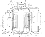
ここで、図5を参照して、冷却媒体として絶縁油を用いた従来の内鉄形送油式変圧器の構成について説明する。すなわち、変圧器タンク1内に鉄心2が配設され、その周囲に内側巻線3及び外側巻線4が巻回されている。また、前記変圧器タンク1の上部には第1の配管11が接続され、この第1の配管11はクーラー9及びポンプ10を介して、前記変圧器タンク1の下部に接続されている。また、バルブ13が設置された第2の配管12が、前記ポンプ10の下流側において前記第1の配管11から分岐され、変圧器タンク1の上部に接続されている。
Here, with reference to FIG. 5, the structure of the conventional inner iron type oil supply type transformer using insulating oil as a cooling medium is demonstrated. That is, the
また、前記変圧器タンク1の上部には、コンサベータ21及びブッシング31が配設され、このコンサベータ21の内部にはゴム膜22が取り付けられ、前記変圧器タンク1とコンサベータ21の間に設置された導通管25によって、コンサベータ21内に絶縁油7が導入されるように構成されている。また、コンサベータ21の上面には呼吸器官23を介して乾燥装置24が接続されている。
Further, a
上記のような構成を有する従来の内鉄形送油式変圧器においては、変圧器タンク1の下部から導入された冷却媒体である絶縁油7は、鉄心2、内側巻線3及び外側巻線4を冷却しながらタンク上部へ移動し、変圧器タンク1の上部から第1の配管11に導入されるように構成されている。そして、第1の配管11に導入された絶縁油7は、前記クーラー9によって冷却された後、ポンプ10によって、変圧器タンク1の下部から再びタンク内に導入されるように構成されている。
In the conventional inner iron type oil-feeding transformer having the above-described configuration, the
一方、バルブ13を開くことによって、ポンプ10の下流側で第1の配管11から分流して第2の配管12に導入された絶縁油7は、変圧器タンク1の上部から再びタンク1内に導入されるように構成されている。
On the other hand, when the
上述したように、図5に示したような冷却媒体として絶縁油を用いた従来の内鉄形送油式変圧器において、冷却媒体である絶縁油が外部に漏れた場合には、環境に与える打撃が大きいため、たとえ、冷却媒体が外部に漏れた場合でも、環境に影響を与えない絶縁冷却媒体を用いることが望まれている。このような環境に影響を与えない絶縁冷却媒体としてはまず水を挙げることができるが、通常の水を使用した場合、絶縁性の点で問題がある。 As described above, in the conventional inner iron type oil supply type transformer using insulating oil as the cooling medium as shown in FIG. 5, when the insulating oil as the cooling medium leaks to the outside, it is given to the environment. Since the impact is great, it is desirable to use an insulating cooling medium that does not affect the environment even if the cooling medium leaks to the outside. An example of such an insulating cooling medium that does not affect the environment is water. However, when normal water is used, there is a problem in terms of insulation.
このような問題点を解決するために、冷却媒体として純水を利用することが知られている(特許文献1参照)。純水は、通常の水と同様に優れた冷却特性を持つため、冷却だけを目的に使用する場合には問題はない。しかし、冷却だけでなく絶縁の機能の適用を考える場合には、電気抵抗と絶縁耐力が問題となる。 In order to solve such problems, it is known to use pure water as a cooling medium (see Patent Document 1). Since pure water has excellent cooling characteristics like normal water, there is no problem when it is used only for cooling. However, when considering application of an insulating function as well as cooling, electrical resistance and dielectric strength are problems.
すなわち、純水は、通常の水に比べて高い抵抗率及び絶縁破壊電圧を持ち、それぞれ大体0.2〜5×10⁶Ω・cm、4〜8kV/mmの値である。(非特許文献1参照)。しかし、一般的な絶縁油の抵抗率及び破壊電圧は、0.1〜10×1014Ω・cm、20〜30kV/mmと高く、純水は絶縁物よりも抵抗率では108倍低く、破壊電圧では約5倍低い(非特許文献2参照)。 That is, pure water has a higher resistivity and dielectric breakdown voltage than normal water, and has values of about 0.2 to 5 × 10 6 Ω · cm and 4 to 8 kV / mm, respectively. (Refer nonpatent literature 1). However, the resistivity and breakdown voltage of a general insulating oil are as high as 0.1 to 10 × 10 14 Ω · cm, 20 to 30 kV / mm, and pure water is 10 8 times lower in resistivity than an insulator. The breakdown voltage is about 5 times lower (see Non-Patent Document 2).
さらに、水は他の物質を溶かしやすい性質を持ち、特にイオンを大量に溶かした場合には、抵抗率や破壊電圧が低下するため、印加電圧が低い変圧器の負荷タップ巻線の限流抵抗器などに適用することが考えられている(特許文献2参照)。 In addition, water has the property of easily dissolving other substances. Especially when a large amount of ions are dissolved, the resistivity and breakdown voltage decrease, so the current limiting resistance of the load tap winding of the transformer with low applied voltage. It is considered to be applied to a container (see Patent Document 2).
一方、交流電圧を直流電圧に変換するサイリスタバルブでは、サイリスタの熱を水で冷却すると共に、各モジュール間の電位差を保つために水をイオン交換器に通して純水にすると共に、直流高電圧部分が印加されているサイリスタモジュール部分を冷却するために、絶縁ホースで絶縁をして循環させる方式を取っている(特許文献3参照)。 On the other hand, in a thyristor valve that converts AC voltage into DC voltage, the heat of the thyristor is cooled with water, and water is passed through an ion exchanger to make pure water in order to maintain the potential difference between the modules. In order to cool the thyristor module part to which the part is applied, an insulating hose is used for insulation and circulation (see Patent Document 3).
このサイリスタモジュールでは、金属に直接純水を接触させて冷却する方式を取っているが、直接金属と接触する面積が限られている場合には、水に溶け込むイオンも多くないために、水が循環する間にイオンは少量しか水に溶け込まないため、イオン交換器の交換は数年に1度の程度で運転が可能であった。 In this thyristor module, pure water is brought into direct contact with the metal to cool it, but when the area directly in contact with the metal is limited, there are not many ions that dissolve in the water. Since only a small amount of ions dissolved in water during circulation, the exchange of the ion exchanger could be operated once every few years.
このように、純水は金属と接触することで金属イオンを溶かし、抵抗率と破壊電圧が低くなるため、純水を絶縁に使用する場合には、サイリスタバルブの適用例からも分かるとおり、限られた部分を冷却する場合には水に溶け込むイオン量が多くないことから、常にイオン交換器で純水に制御すると共に、電位差がある部分には長い絶縁距離で利用されている。 In this way, pure water dissolves metal ions when it comes into contact with the metal, and the resistivity and breakdown voltage are lowered.Therefore, when pure water is used for insulation, as can be seen from the application example of thyristor valves, it is limited. Since the amount of ions dissolved in the water is not large when the portion is cooled, it is always controlled to pure water by an ion exchanger, and the portion having a potential difference is utilized with a long insulation distance.
このように、従来、水のみを用いて絶縁をしようとすると、水に溶けるイオンを取り除き、常に純水の状態で絶縁したい部分に行き渡らせる必要がある。一方、その結果、コイル部分及び鉄心部分と水とが接触する面積は非常に大きくなる。
通常、変圧器では、絶縁と冷却を行う液体又は気体の絶縁媒体は、コイルの下部から上部に流れるようになっている。従来の変圧器と同様に水をコイル下部から上部に流すと、コイル下部では純水であったものが、上部に行くに従い、コイルとの接触で銅イオンを含むようになり、コイル上部ではイオンを大量に含む水になり、絶縁が保てなくなると予想されていたため、今までは水は変圧器の絶縁・冷却媒体として利用されていなかった。 Usually, in a transformer, a liquid or gaseous insulating medium that performs insulation and cooling flows from the lower part to the upper part of the coil. When water is flowed from the lower part of the coil to the upper part as in a conventional transformer, the pure water at the lower part of the coil will contain copper ions as it goes to the upper part. In the past, water was not used as an insulation / cooling medium for transformers because it was expected that the water would contain a large amount of water and insulation could not be maintained.
この原因として以下のことが考えられる。変圧器は絶縁・冷却媒体と固体絶縁物の複合絶縁の構成をとっており、油入変圧器の絶縁油、ガス絶縁変圧器のSF6ガス共に誘電率が固体絶縁物よりも小さい。この結果、絶縁油、SF6ガス共に固体絶縁物よりも電位分担が大きいため、高い絶縁性能を持つ絶縁・冷却媒体が必要であるとの認識が一般的であった。 The following can be considered as the cause. The transformer has a structure of composite insulation of an insulating / cooling medium and a solid insulator, and both the insulating oil of the oil-filled transformer and the SF6 gas of the gas-insulated transformer have a dielectric constant smaller than that of the solid insulator. As a result, since both the insulating oil and SF6 gas share a larger potential than the solid insulator, it is generally recognized that an insulating / cooling medium having high insulating performance is necessary.
このため、固体絶縁物より低い絶縁特性を有する純水を使用しても、純水に分担される電位より水の絶縁耐力が小さいとの予想で、水を変圧器の絶縁・冷却媒体に使用することはなかった。さらに、変圧器内部にはタンク、鉄心等の金属部分が多数存在するために、純水に金属が溶ける結果、さらに絶縁耐力が低下するために、純水を絶縁・冷却媒体に使用することは困難と考えられていた。 For this reason, even if pure water with lower insulation properties than solid insulators is used, it is expected that the dielectric strength of water will be lower than the potential shared by pure water, and water will be used as the insulation and cooling medium for transformers. I never did. In addition, since there are many metal parts such as tanks and iron cores inside the transformer, the metal is dissolved in pure water, resulting in a further decrease in dielectric strength. It was considered difficult.
しかしながら、水の比誘電率が81であるのに対して、通常の固体絶縁物である高分子絶縁物の比誘電率は4程度であるために、交流や雷インパルス印加時には、水側に分担する電位は高分子絶縁物の約20分の1となる。また、通常の固体絶縁物の破壊電圧が60〜100kV/mm程度であるのに対して、純水の絶縁破壊電圧は先に述べたように4〜8kV/mmであり、100kV/mmの約20分の1とバランスが取れている。 However, the relative permittivity of water is 81, whereas the relative permittivity of a polymer insulator, which is a normal solid insulator, is about 4, so that it is shared to the water side when alternating current or lightning impulse is applied. The potential to be applied is about 1/20 of that of the polymer insulator. Further, the breakdown voltage of a normal solid insulator is about 60 to 100 kV / mm, whereas the dielectric breakdown voltage of pure water is 4 to 8 kV / mm as described above, which is about 100 kV / mm. Balanced with 1/20.
そこで、本発明者等は、イオンが水に大量に溶けて絶縁耐力が低下しなければ、従来の油入変圧器やガス絶縁変圧器と同様の大きさの変圧器が製造できるとの見地から鋭意検討を重ね、本発明を完成させるに至ったものである。 Therefore, from the viewpoint that the present inventors can manufacture a transformer of the same size as a conventional oil-filled transformer or gas-insulated transformer if the ions are dissolved in water in large quantities and the dielectric strength does not decrease. As a result of intensive studies, the present invention has been completed.
すなわち、本発明は、上述したような従来技術の問題点を解決するために提案されたものであり、その目的は、純水を絶縁と冷却に使用しながら小型で信頼性の高い変圧器を提供することにある。 That is, the present invention has been proposed in order to solve the above-described problems of the prior art, and its purpose is to provide a small and reliable transformer while using pure water for insulation and cooling. It is to provide.
上記の課題を解決するために、請求項1に記載の変圧器は、絶縁冷却媒体として純水が用いられ、変圧器タンクの外部に設けられた純水冷却手段と前記変圧器タンクとを循環する純水循環系が構成され、変圧器を構成する部材の内、前記純水と接する部分に気密性の高い被覆が施され、前記純水循環系の内面に気密性の高い被覆が施され、この純水循環系にイオン除去手段が設けられていることを特徴とするものである。
In order to solve the above problems, the transformer according to
上記のような構成を有する請求項1に記載の発明によれば、絶縁冷却媒体として用いられる純水が直接金属に接触することがないため、金属イオンが純水中に溶け込む量が非常に少なくなる。その結果、コイル上部において、水の抵抗率及び絶縁破壊電圧が低下することを防止できる。また、純水の循環系にイオン除去手段を設けたことにより、水の抵抗率及び絶縁耐力をより高精度に保つことができる。なお、変圧器を構成する部材の内、純水と接する部分とは、冷却媒体(純水)を循環させる配管、クーラー、ポンプ、タンク、コンサベータ等の部品である。
According to the invention described in
また、請求項2に記載の変圧器は、絶縁冷却媒体として純水及び水が用いられ、変圧器タンクの外部に設けられた純水冷却手段と前記変圧器タンク内の所定の部位とを循環する純水循環系が構成されると共に、変圧器タンクの外部に設けられた水冷却手段と前記変圧器タンク内の所定の部位とを循環する水循環系が構成され、変圧器を構成する部材の内、前記純水と接する部分に気密性の高い被覆が施され、前記純水循環系の内面に気密性の高い被覆が施され、この純水循環系にイオン除去手段が設けられていることを特徴とするものである。
The transformer according to
上記のような構成を有する請求項2に記載の発明によれば、請求項1と同様の作用効果が得られるだけでなく、絶縁冷却媒体として純水と水を用い、高い絶縁性能を要求される巻線部分等には純水を用い、絶縁性能を要求されない鉄心部分等には水を用いているため、気密性の高い被覆を施す部位を最小限に抑えることができる。
According to the invention described in
以上述べたように、本発明によれば、イオンが水に溶ける量を低減することで純水の維持が容易になるため、純水を絶縁と冷却に使用しながら小型で信頼性の高い変圧器を提供することができる。 As described above, according to the present invention, since the maintenance of pure water is facilitated by reducing the amount of ions dissolved in water, a small and highly reliable transformer can be used while using pure water for insulation and cooling. Can be provided.
以下、本発明の実施形態について図面を参照して説明する。なお、図5に示した従来型と同様の部材には同様の符号を付して説明は省略する。 Embodiments of the present invention will be described below with reference to the drawings. In addition, the same code | symbol is attached | subjected to the member similar to the conventional type shown in FIG. 5, and description is abbreviate | omitted.
(1)第1実施形態
(1−1)構成
本実施形態においては、冷却媒体として純水5が用いられ、この純水中に変圧器の巻線3,4、鉄心2等の構造物が配置されている。また、変圧器タンク1の上部に接続された第1の配管11には、純水冷却用クーラー30及び純水循環用ポンプ32が順次接続され、さらにその下流側には、イオン交換樹脂を封入した純水器33(請求項のイオン除去手段に対応)が接続されている。
(1) Configuration of the First Embodiment (1-1) In this embodiment,
そして、前記第1の配管11は、前記純水器33の下流側で、変圧器タンク1の下部に接続されている。また、バルブ13が設置された第2の配管12が、前記純水器33の下流側において前記第1の配管11から分岐され、変圧器タンク1の上部に接続されている。なお、前記第2の配管12は、純水循環用ポンプ32の排出量が変えられない場合に、タンク1内に流れる純水の量を適宜調整するために設けられている。
The
また、本実施形態においては、内側巻線3及び外側巻線4としては、図2に示すように、気密性の高い被覆42として例えばダイヤモンドライクカーボン(DLC)でコーティングした銅線41の外側に高分子フィルム43を巻いた素線40を、高分子製の円筒に高分子製のレールを配置したものの回りに巻いたものが用いられる。また、鉄心2としては、酢酸セルロースでコーティングした薄板の珪素鋼板を重ねて束ねたものが用いられる。
In the present embodiment, as shown in FIG. 2, the inner winding 3 and the outer winding 4 are formed on the outside of the
さらに、本実施形態においては、変圧器タンク1、第1の配管11、第2の配管12、純水冷却用クーラー30、純水循環用ポンプ32及び純水器33の内面にも、酢酸セルロースによるコーティングが施されている。また、変圧器上部に取り付けられたコンサベータ21の内面、及び内部に取り付けられたゴム膜22には、ダイヤモンドライクカーボン(DLC)によるコーティングが施されている。
Furthermore, in this embodiment, cellulose acetate is also applied to the inner surfaces of the
なお、コーティングを施す部位により、酢酸セルロースによるコーティングとダイヤモンドライクカーボン(DLC)によるコーティングとを区別して適用しているのは、酢酸セルロースには柔軟性があるが、DLCには柔軟性がないため、柔らかいものにDLCを取り付けると割れてしまうからである。 Note that the cellulose acetate coating and the diamond-like carbon (DLC) coating are applied differently depending on the part to be coated because cellulose acetate is flexible, but DLC is not flexible. This is because if DLC is attached to a soft material, it will break.
(1−2)作用
以上のような構成を有する本実施形態においては、変圧器タンク1の下部から導入された冷却媒体である純水5は、鉄心2、内側巻線3及び外側巻線4を冷却しながらタンク上部へ移動し、前記変圧器タンク1の上部から第1の配管11に導入される。
(1-2) Operation In the present embodiment having the above-described configuration,
第1の配管11に導入された純水5は、前記純水冷却用クーラー30によって冷却された後、純水循環用ポンプ32によって純水器33に導入され、純水器33に封入されたイオン交換樹脂でイオンを取り除かれた後、変圧器タンク1の下部から再びタンク1内に導入される。
The
この場合、本実施形態においては、変圧器タンク1、第1の配管11、第2の配管12、純水冷却用クーラー30、純水循環用ポンプ32及び純水器33の内面には、酢酸セルロースによってコーティングが施されているため、冷却媒体である純水5がこれらと接触しても、純水5に溶け込むイオンの量は非常に小さい。
In this case, in this embodiment, acetic acid is formed on the inner surfaces of the
その結果、本実施形態において絶縁冷却媒体として用いられる純水5は、高い抵抗率と絶縁耐力を循環中の全ての状態で維持しながら変圧器タンク1の下部からタンク内に導入され、変圧器の巻線及び鉄心を冷却した後、タンク上部に接続された配管から純水冷却用クーラー30に戻される。
As a result, the
さらに、本実施形態においては、変圧器上部に取り付けられたコンサベータ21の内部に取り付けられたゴム膜22にもダイヤモンドライクカーボン(DLC)によるコーティングが施されているため、ゴム膜22を介して空気が透過されることを防止できる。その結果、酸素、窒素等のイオンが水に溶け込むことを防止できるので、水の抵抗率及び絶縁破壊電圧が低下することを防止できる。
Furthermore, in this embodiment, since the
(1−3)効果
以上述べたように、本実施形態によれば、純水を絶縁冷却媒体として使用し、イオン源となる金属及び外気と接するゴム等に、ダイヤモンドライクカーボン(DLC)や酢酸セルロースによる気密性の高い被覆を施すことにより、純水へのイオンの溶け込みを最小限にすると共に、イオン交換樹脂を用いたイオン除去手段(純水器33)を純水の循環系に取り付けることで、純水の維持が容易になるため、巻線の上部においても絶縁性能の低下を防止することができる。その結果、純水を絶縁と冷却に使用した、小型で信頼性の高い変圧器を得ることができる。
(1-3) Effect As described above, according to the present embodiment, diamond-like carbon (DLC) or acetic acid is used for a metal that serves as an ion source and rubber that is in contact with the outside air using pure water as an insulating cooling medium. By applying a highly airtight coating with cellulose, ion dissolution into pure water is minimized, and ion removal means (deionizer 33) using ion exchange resin is attached to the pure water circulation system. Thus, since it is easy to maintain pure water, it is possible to prevent a decrease in insulation performance even at the upper part of the winding. As a result, a compact and highly reliable transformer using pure water for insulation and cooling can be obtained.
(2)第2実施形態
(2−1)構成
本実施形態においては、冷却媒体として純水5及び水6が用いられ、鉄心2を冷却する水6と、巻線及びその他の部分を冷却する純水5とをそれぞれ別個の循環系を用いて、タンク内に循環供給するように構成されている。
(2) Configuration of the Second Embodiment (2-1) In this embodiment,
すなわち、図3に示すように、内側巻線3及び外側巻線4はFRP等からなる絶縁容器50内に配置され、この絶縁容器50の上部には第3の配管51が接続され、変圧器タンク1の外側に引き出されている。この第3の配管51には、純水冷却用クーラー30及び純水循環用ポンプ32が順次接続され、さらにその下流側に設置されたイオン交換樹脂を封入した純水器33を介して、前記絶縁容器50の下部に接続されている。
That is, as shown in FIG. 3, the inner winding 3 and the outer winding 4 are arranged in an insulating
また、前記純水循環用ポンプ32と純水器33の間において、前記第3の配管51から第4の配管52が分岐され、前記純水冷却用クーラー30の上流側で前記第3の配管51に接続されている。また、この第4の配管52には、バルブ13が設置されている。なお、前記第4の配管52は、純水循環用ポンプ32の排出量が変えられない場合に、絶縁容器50内に流れる純水の量を変えるために設けられている。従って、純水器33を通す必要がないため、純水器33の上流側で前記第3の配管51から分岐されている。
Further, a
一方、変圧器タンク1の上部に接続された第1の配管11には、水冷却用クーラー53及び水循環用ポンプ54が設置され、さらに、バルブ13が設置された第2の配管12が、前記水循環用ポンプ54の下流側で第1の配管11から分岐され、変圧器タンク1の上部に接続されている。なお、この第2の配管12は、水循環用ポンプ54の排出量が変えられない場合に、タンク1内に流れる水の量を変えるために設けられている。
On the other hand, in the
そして、前記第1の配管11を介して、前記絶縁容器50の外側の空間に水6が循環供給され、これにより、前記絶縁容器50の外側の空間に配置された鉄心2が、水6によって冷却されるように構成されている。
Then, the
また、本実施形態においても、上記第1実施形態と同様に、図2に示すように、内側巻線3及び外側巻線4としては、気密性の高い被覆42としてダイヤモンドライクカーボンでコーティングした銅線41の外側に高分子フィルム43を巻いた素線40を、高分子製の円筒に高分子製のレールを配置したものの回りに巻いたものが用いられる。なお、本実施形態においては、鉄心部分にはコーティング処理は不要である。
Also in this embodiment, as in the first embodiment, as shown in FIG. 2, the inner winding 3 and the outer winding 4 are copper coated with diamond-like carbon as a highly
さらに、本実施形態においては、絶縁容器50、第3の配管51、第4の配管52、純水冷却用クーラー30、純水循環用ポンプ32及び純水器33の内面には、酢酸セルロースによるコーティングが施されている。また、変圧器上部に取り付けられたコンサベータ21の内面、及び内部に取り付けられたゴム膜22には、ダイヤモンドライクカーボンによるコーティングが施されている。
Furthermore, in this embodiment, the inner surfaces of the insulating
(2−2)作用
以上のような構成を有する本実施形態においては、絶縁性能を要求される巻線3、4を冷却する純水5は、第3の配管51を介して変圧器タンク1内に配設された絶縁容器50の下部から該容器内に導入され、内側巻線3及び外側巻線4を冷却しながら絶縁容器50の上部に移動し、絶縁容器50の上部から第3の配管51に導入される。
(2-2) Operation In the present embodiment having the above-described configuration, the
第3の配管51に導入された純水5は、純水冷却用クーラー30によって冷却された後、純水循環用ポンプ32によって純水器33に導入され、純水器33に封入されたイオン交換樹脂でイオンを取り除かれた後、変圧器タンク1の下部から再び絶縁容器50内に導入される。
The
一方、絶縁性能を要求されない巻線以外の部分、特に鉄心2を冷却する水6は、変圧器タンク1の下部からタンク内に導入され、鉄心2を冷却しながらタンク上部へ移動し、変圧器タンク1の上部から第1の配管11に導入される。第1の配管11に導入された水6は、前記水冷却用クーラー53によって冷却された後、水循環用ポンプ54によって変圧器タンク1の下部から再びタンク内に導入される。
On the other hand,
このように、本実施形態においては、絶縁容器50、第3の配管51、第4の配管52、純水冷却用クーラー30、純水循環用ポンプ32及び純水器33の内面には、酢酸セルロースによってコーティングが施されているため、冷却媒体である純水5がこれらと接触しても、純水にとけ込むイオンの量は非常に小さい。
Thus, in the present embodiment, acetic acid is not formed on the inner surfaces of the insulating
その結果、冷却媒体である純水5は、高い抵抗率と絶縁耐力を循環中の全ての状態で維持しながら変圧器タンク内に設置された絶縁容器50の下部から入り、変圧器の巻線を冷却した後、絶縁容器50の上部に接続された配管から純水冷却用クーラー30に戻される。
As a result, the
さらに、本実施形態においては、絶縁性能を要求されない巻線以外の部分の冷却には水6を用いているため、タンク内面、鉄心部分には気密性の被覆をする必要がない。
Furthermore, in this embodiment, since
(2−3)効果
以上述べたように、本実施形態においては、絶縁性能を要求されない鉄心部分の冷却媒体(水)が循環する系と、絶縁性能を要求される巻線部分の冷却媒体(純水)が循環する系とを分離して構成することにより、気密性の被覆を必要とする部分を少なくすることができるだけでなく、純水とイオンの発生源との接触も少なくすることができるため、必要とするイオン交換樹脂の量を少なくすることができる。また、鉄心を構成する薄い珪素鋼鈑すべてに気密性の優れた被覆をする必要がなくなるため、コストを削減することができる。
(2-3) Effects As described above, in the present embodiment, the cooling medium (water) of the iron core portion that does not require insulation performance circulates, and the cooling medium (winding portion cooling medium that requires insulation performance ( By separating and separating the system from which pure water is circulated, not only can the number of parts that require airtight coating be reduced, but also the contact between the pure water and the ion source can be reduced. Therefore, the required amount of ion exchange resin can be reduced. Moreover, since it is not necessary to coat all the thin silicon steel plates constituting the iron core with excellent airtightness, the cost can be reduced.
(3)第3実施形態
(3−1)構成
本実施形態は、上記第2実施形態の変形例であって、図4に示したように、鉄心2を冷却する水6が循環する系と、巻線3、4及びその他の部分を冷却する純水5が循環する系とを分離して構成する場合に、鉄心2を密閉容器60内に収納配置し、鉄心2を冷却する水6が、前記密閉容器60の上部に接続された第5の配管61を介して変圧器タンク1の外側に引き出されるように構成したものである。
(3) Third Embodiment (3-1) Configuration This embodiment is a modification of the second embodiment, and as shown in FIG. 4, a system in which
この第5の配管61には、水冷却用クーラー53及び水循環用ポンプ54が設置され、さらに、バルブ13が設置された第6の配管62が、前記水循環用ポンプ54の下流側で第5の配管61から分岐され、前記水冷却用クーラー53の上流側で前記第5の配管61に接続されている。なお、この第6の配管62は、水循環用ポンプ54の排出量が変えられない場合に、密閉容器60内に流れる水の量を変えるために設けられている。
The
そして、前記第5の配管61を介して、鉄心2を収納した密閉容器60の下部に水6が循環供給され、これにより、鉄心2が水6によって冷却されるように構成されている。
Then, the
一方、変圧器タンク1の上部に接続された第1の配管11には、純水冷却用クーラー30及び純水循環用ポンプ32が設置され、さらにその下流側に、イオン交換樹脂を封入した純水器33が設置されている。そして、前記第1の配管11は、前記純水器33の下流側で、変圧器タンク1の下部に接続されている。また、バルブ13が設置された第2の配管12が、前記純水器33の下流側において前記第1の配管11から分岐され、変圧器タンク1の上部に接続されている。
On the other hand, a pure water cooling cooler 30 and a pure
(3−2)作用
以上のような構成を有する本実施形態においては、絶縁性能を要求される巻線3、4を冷却する純水5は変圧器タンク1の下部から導入され、内側巻線3及び外側巻線4を冷却しながら変圧器タンク1の上部に移動し、第1の配管11に導入される。
(3-2) Operation In the present embodiment having the above-described configuration,
第1の配管11に導入された純水5は、純水冷却用クーラー30によって冷却された後、純水循環用ポンプ32によって純水器33に導入され、純水器33に封入されたイオン交換樹脂でイオンを取り除かれた後、変圧器タンク1の下部から再びタンク内に導入される。
The
一方、絶縁性能を要求されない鉄心2を冷却する水6は、鉄心2を収納した密閉容器60の下部から導入され、鉄心2を冷却しながら上方へ移動し、密閉容器60の上部から第5の配管61に導入される。第5の配管61に導入された水6は、前記水冷却用クーラー53によって冷却された後、水循環用ポンプ54によって変圧器タンク1の下部から再び前記密閉容器60内に導入される。
On the other hand, the
このように、本実施形態においては、変圧器タンク1、純水が循環する第1の配管11、第2の配管12、純水冷却用クーラー30、純水循環用ポンプ32及び純水器33の内面には、酢酸セルロースによってコーティングが施されているため、冷却媒体である純水5がこれらと接触しても、純水にとけ込むイオンの量は非常に小さい。
Thus, in this embodiment, the
その結果、冷却媒体である純水5は、高い抵抗率と絶縁耐力を循環中の全ての状態で維持しながら変圧器タンクの下部から入り、変圧器の巻線を冷却した後、タンク上部に設けられた配管から純水冷却用クーラー30に戻される。さらに、本実施形態においては、絶縁性能を要求されない鉄心部分には特に気密性の優れたコーティングを施さず、また、鉄心部分の冷却には水6を用いているため、この水の循環系にも気密性の被覆をする必要がない。
As a result, the
(3−3)効果
以上述べたように、本実施形態においては、絶縁性能を要求されない鉄心部分の冷却媒体(水)が循環する系と、絶縁性能を要求される巻線部分の冷却媒体(純水)が循環する系とを分離して構成することにより、気密性の被覆を必要とする部分を少なくすることができるだけでなく、純水とイオンの発生源との接触も少なくすることができるため、必要とするイオン交換樹脂の量を少なくすることができる。また、鉄心を構成する薄い珪素鋼鈑すべてに気密性の優れた被覆をする必要がなくなるため、コストを削減することができる。
(3-3) Effect As described above, in the present embodiment, the cooling medium (water) in the iron core portion that does not require insulation performance circulates, and the cooling medium (in the winding portion that requires insulation performance ( By separating and separating the system from which pure water is circulated, not only can the number of parts that require airtight coating be reduced, but also the contact between the pure water and the ion source can be reduced. Therefore, the required amount of ion exchange resin can be reduced. Moreover, since it is not necessary to coat all the thin silicon steel plates constituting the iron core with excellent airtightness, the cost can be reduced.
(4)他の実施形態
なお、本発明は、上述したような実施形態に限定されるものではなく、以下に示すような変形例も考えられる。すなわち、上記第2実施形態及び第3実施形態のように、純水装置を取り付けない水を用いた冷却系を用いた装置では、水の代わりに窒素、空気などを冷却媒体として使用し、ポンプの代わりにガスブロアでガスを循環して冷却することもできる。
(4) Other Embodiments The present invention is not limited to the above-described embodiments, and the following modifications may be considered. That is, as in the second embodiment and the third embodiment, in a device using a cooling system using water to which no pure water device is attached, nitrogen, air or the like is used as a cooling medium instead of water, and the pump Instead of this, gas can be circulated with a gas blower for cooling.
また、図示はしていないが、素線の銅線を中空にして、中空の内側にダイヤモンドライクコーティングを施すと共に、内部に水を通すことで冷却効率を上げることができる。 Although not shown in the figure, it is possible to increase the cooling efficiency by making the copper wire of the wire hollow, applying diamond-like coating inside the hollow, and passing water through the inside.
また、素線の被覆としてポリエチレンのフィルムを巻くのではなく、銅線の周りにポリエチレンをダイスによる押し出しで被覆層を設けたケーブルを作製し、そのポリエチレンのケーブルの周りにダイヤモンドライクコーティングを施すことで、ポリエチレンに含まれるイオンが水に溶け込むことを防止できる。この結果、純水の維持が行いやすく、イオン交換樹脂の交換期間の長期化ができるようになり経済性が高くなる。さらに、素線の被覆として酢酸セルロースを使用することで、銅線のコーティングをする必要がなくなる。 Also, instead of winding a polyethylene film as a covering for the strands, make a cable with a coating layer by extruding polyethylene around the copper wire with a die, and apply a diamond-like coating around the polyethylene cable Thus, it is possible to prevent ions contained in the polyethylene from being dissolved in water. As a result, it is easy to maintain pure water, and the replacement period of the ion exchange resin can be extended, resulting in high economic efficiency. Furthermore, the use of cellulose acetate as a covering for the strands eliminates the need for copper wire coating.
また、上記の実施形態においては、イオン除去手段としてイオン交換樹脂を用いたが、逆浸透膜を使用することもできる。すなわち、逆浸透膜をチューブ状に形成し、このチューブを複数束ねて大きな表面積を持たせ、チューブ内側に圧力を加えることにより、水分子より小さな分子が透過可能になるため純水を得ることができる。なお、この逆浸透膜としては、例えば、芳香族ポリアミドあるいは酢酸セルロースを用いることができる。 In the above embodiment, the ion exchange resin is used as the ion removing means, but a reverse osmosis membrane can also be used. That is, a reverse osmosis membrane is formed in a tube shape, a plurality of tubes are bundled to have a large surface area, and by applying pressure to the inside of the tube, molecules smaller than water molecules can permeate so that pure water can be obtained. it can. As the reverse osmosis membrane, for example, aromatic polyamide or cellulose acetate can be used.
また、上記逆浸透膜を気密性の高い被覆として用いることもできる。すなわち、上記逆浸透膜は、圧力を加えても水分子よりも大きな物質は通しにくい性質を持つため、水分子より大きなイオンを透過させない目的で、タンク等の表面に気密性の高い被覆として用いることもできる。その結果、タンクから水に鉄等のイオンが溶け出すのを防止することができる。 The reverse osmosis membrane can also be used as a highly airtight coating. That is, the reverse osmosis membrane has a property that it is difficult for a substance larger than water molecules to pass through even when pressure is applied, so that it is used as a highly airtight coating on the surface of a tank or the like for the purpose of preventing ions larger than water molecules from passing You can also As a result, it is possible to prevent ions such as iron from dissolving from the tank into the water.
上記のような変圧器は、変電所などで使用する200MVAを超えるような大容量の変圧器で説明したが、これに限ったものでなく1MVA以下の領域までの変圧器でも作用効果は変わらない。さらに、災害時の復興用などの一時的に変圧器を必要とする場所で用いられるトレーラに載せて移動するタイプの変圧器にも適している。 The above-described transformer has been described as a large-capacity transformer exceeding 200 MVA used in substations, etc., but is not limited to this, and the effect is not changed even with a transformer up to 1 MVA or less. . Furthermore, it is also suitable for a transformer of a type that moves on a trailer that is used in a place where a transformer is temporarily required, such as for reconstruction in the event of a disaster.
1…タンク
2…鉄心
3…内側巻線
4…外側巻線
5…純水
6…水
7…絶縁油
8…純水器
9…クーラー
10…ポンプ
11…第1の配管
12…第2の配管
13…バルブ
21…コンサベータ
22…ゴム膜
23…呼吸器管
24…乾燥装置
25…導通管
30…純水冷却用クーラー
31…ブッシング
32…純水循環用ポンプ
33…純水器
40…素線
41…銅線
42…気密性の高い被覆
43…高分子フィルム
50…絶縁容器
51…第3の配管
52…第4の配管
53…水冷却用クーラー
54…水循環用ポンプ
60…密閉容器
61…第5の配管
62…第6の配管
DESCRIPTION OF
Claims (10)
変圧器タンクの外部に設けられた純水冷却手段と前記変圧器タンクとを循環する純水循環系が構成され、
変圧器を構成する部材の内、前記純水と接する部分に気密性の高い被覆が施され、
前記純水循環系の内面に気密性の高い被覆が施され、
この純水循環系にイオン除去手段が設けられていることを特徴とする変圧器。 Pure water is used as an insulating cooling medium,
A pure water circulation system configured to circulate between the pure water cooling means provided outside the transformer tank and the transformer tank;
Of the members constituting the transformer, a coating with high airtightness is applied to the portion in contact with the pure water,
A highly airtight coating is applied to the inner surface of the pure water circulation system,
A transformer characterized in that an ion removing means is provided in the pure water circulation system .
変圧器タンクの外部に設けられた純水冷却手段と前記変圧器タンク内の所定の部位とを循環する純水循環系が構成されると共に、
変圧器タンクの外部に設けられた水冷却手段と前記変圧器タンク内の所定の部位とを循環する水循環系が構成され、
変圧器を構成する部材の内、前記純水と接する部分に気密性の高い被覆が施され、
前記純水循環系の内面に気密性の高い被覆が施され、
この純水循環系にイオン除去手段が設けられていることを特徴とする変圧器。 Pure water and water are used as the insulating cooling medium,
A pure water circulation system for circulating pure water cooling means provided outside the transformer tank and a predetermined part in the transformer tank is configured,
A water circulation system for circulating water cooling means provided outside the transformer tank and a predetermined part in the transformer tank is configured,
Of the members constituting the transformer, a coating with high airtightness is applied to the portion in contact with the pure water,
A highly airtight coating is applied to the inner surface of the pure water circulation system,
A transformer characterized in that an ion removing means is provided in the pure water circulation system .
Priority Applications (1)
| Application Number | Priority Date | Filing Date | Title |
|---|---|---|---|
| JP2008162492A JP5348948B2 (en) | 2008-06-20 | 2008-06-20 | Transformer |
Applications Claiming Priority (1)
| Application Number | Priority Date | Filing Date | Title |
|---|---|---|---|
| JP2008162492A JP5348948B2 (en) | 2008-06-20 | 2008-06-20 | Transformer |
Publications (2)
| Publication Number | Publication Date |
|---|---|
| JP2010003931A JP2010003931A (en) | 2010-01-07 |
| JP5348948B2 true JP5348948B2 (en) | 2013-11-20 |
Family
ID=41585391
Family Applications (1)
| Application Number | Title | Priority Date | Filing Date |
|---|---|---|---|
| JP2008162492A Active JP5348948B2 (en) | 2008-06-20 | 2008-06-20 | Transformer |
Country Status (1)
| Country | Link |
|---|---|
| JP (1) | JP5348948B2 (en) |
Families Citing this family (9)
| Publication number | Priority date | Publication date | Assignee | Title |
|---|---|---|---|---|
| EP2696358B1 (en) * | 2012-08-10 | 2018-10-10 | STS Spezial-Transformatoren-Stockach GmbH & Co. KG | Medium frequency transformer |
| CN104183368B (en) * | 2013-05-22 | 2018-01-23 | 上海东普电器制造有限公司 | The double water cooling synthesis cooling systems of clean energy resource transformer |
| CN103448602B (en) * | 2013-09-13 | 2015-12-30 | 国家电网公司 | Voltage transformer auxiliary temperature-reducing car |
| KR101864625B1 (en) * | 2014-08-12 | 2018-06-07 | 엘에스산전 주식회사 | Cooling System for Power Transformer |
| CN104269250A (en) * | 2014-10-21 | 2015-01-07 | 江苏天利机电有限公司 | Water cooling dry type transformer |
| CN106024305B (en) * | 2016-05-23 | 2018-01-02 | 江苏瑞恩电气股份有限公司 | A kind of dry-type transformer and its control system with heat abstractor |
| CN107493673A (en) * | 2017-08-16 | 2017-12-19 | 中国原子能科学研究院 | A kind of high-voltage isolating powerful device cooling system |
| CN108022721A (en) * | 2018-01-09 | 2018-05-11 | 张云戈 | A kind of subway transformer radiator and subway transformer |
| CN111883342B (en) * | 2020-08-18 | 2021-03-30 | 江苏鹤都电器有限公司 | Dry-type transformer cooling device with intelligent frequency conversion function |
Family Cites Families (10)
| Publication number | Priority date | Publication date | Assignee | Title |
|---|---|---|---|---|
| JPS51103647U (en) * | 1975-02-18 | 1976-08-19 | ||
| JPH01111310A (en) * | 1987-10-26 | 1989-04-28 | Toshiba Corp | Static induction device |
| JPH01147816A (en) * | 1987-12-04 | 1989-06-09 | Toshiba Corp | Stationary induction apparatus |
| JP2553157B2 (en) * | 1988-08-03 | 1996-11-13 | 株式会社東芝 | Stationary induction equipment |
| JPH0790219B2 (en) * | 1990-08-01 | 1995-10-04 | 日本錬水株式会社 | Pure water production apparatus and production method |
| JPH05212252A (en) * | 1992-02-04 | 1993-08-24 | Toray Ind Inc | Reverse-osmosis liquid separator |
| JPH05315150A (en) * | 1992-05-13 | 1993-11-26 | Toshiba Corp | Foil-wound transformer |
| DE19945855A1 (en) * | 1999-09-24 | 2001-03-29 | Bosch Gmbh Robert | High inductance micro-coil constructed on substrate, useful at higher currents is formed using additive- or doping technology with diamond or diamond-like material in insulator |
| JP2003022911A (en) * | 2001-07-10 | 2003-01-24 | Fuji Electric Corp Res & Dev Ltd | Thin film coil module, its manufacturing method and its using method |
| US7002443B2 (en) * | 2003-06-25 | 2006-02-21 | Cymer, Inc. | Method and apparatus for cooling magnetic circuit elements |
-
2008
- 2008-06-20 JP JP2008162492A patent/JP5348948B2/en active Active
Also Published As
| Publication number | Publication date |
|---|---|
| JP2010003931A (en) | 2010-01-07 |
Similar Documents
| Publication | Publication Date | Title |
|---|---|---|
| JP5348948B2 (en) | Transformer | |
| EP2445068B1 (en) | Gas insulation apparatus | |
| TW319873B (en) | ||
| US7939752B2 (en) | Elongated member and use thereof | |
| US2561738A (en) | Cooling and insulating electrical apparatus | |
| US8659378B2 (en) | Electric transformer with improved cooling system | |
| US20120092108A1 (en) | Liquid cooled magnetic component with indirect cooling for high frequency and high power applications | |
| US10910138B2 (en) | Gas-insulated electrical apparatus, in particular gas-insulated transformer or reactor | |
| CN102754296B (en) | Extremely low temperature cable terminal connector | |
| US20120120537A1 (en) | Current fault limiter with live tank | |
| US2173717A (en) | Electrical system of power transmission | |
| CN101878572A (en) | High voltage fault current limiter having immersed phase coils | |
| KR20070117480A (en) | System having a superconductive cable | |
| Peter | Calculations for short circuit withstand capability of a distribution transformer | |
| CA2866304A1 (en) | Fuses | |
| KR101400312B1 (en) | Electric fault current limiter having superconducting elements inside a cryogenic vessel and bushings for connecting an external circuit | |
| CN205248064U (en) | Sulfur hexafluoride gas -insulated transformer | |
| KR101635662B1 (en) | Transformer | |
| JPH05315150A (en) | Foil-wound transformer | |
| JP2005341737A (en) | Terminal structure of superconducting apparatus | |
| CN104685576A (en) | Electrical insulator comprising organofluorine compound and method for producing same | |
| Mukaiyama et al. | Development of a perfluorocarbon liquid immersed prototype large power transformer with compressed SF/sub 6/gas insulation | |
| Holman | Gas Insulated Transformers (GYTs) | |
| JPS6182408A (en) | Gas insulated stationary induction electric apparatus | |
| JP2002015923A (en) | Static induction apparatus |
Legal Events
| Date | Code | Title | Description |
|---|---|---|---|
| A621 | Written request for application examination |
Free format text: JAPANESE INTERMEDIATE CODE: A621 Effective date: 20110519 |
|
| A977 | Report on retrieval |
Free format text: JAPANESE INTERMEDIATE CODE: A971007 Effective date: 20121212 |
|
| A131 | Notification of reasons for refusal |
Free format text: JAPANESE INTERMEDIATE CODE: A131 Effective date: 20121225 |
|
| A521 | Written amendment |
Free format text: JAPANESE INTERMEDIATE CODE: A523 Effective date: 20130225 |
|
| A131 | Notification of reasons for refusal |
Free format text: JAPANESE INTERMEDIATE CODE: A131 Effective date: 20130507 |
|
| TRDD | Decision of grant or rejection written | ||
| A01 | Written decision to grant a patent or to grant a registration (utility model) |
Free format text: JAPANESE INTERMEDIATE CODE: A01 Effective date: 20130723 |
|
| A61 | First payment of annual fees (during grant procedure) |
Free format text: JAPANESE INTERMEDIATE CODE: A61 Effective date: 20130820 |
|
| R151 | Written notification of patent or utility model registration |
Ref document number: 5348948 Country of ref document: JP Free format text: JAPANESE INTERMEDIATE CODE: R151 |