JP5348168B2 - Nail printing device - Google Patents

Nail printing device Download PDF

Info

Publication number
JP5348168B2
JP5348168B2 JP2011079684A JP2011079684A JP5348168B2 JP 5348168 B2 JP5348168 B2 JP 5348168B2 JP 2011079684 A JP2011079684 A JP 2011079684A JP 2011079684 A JP2011079684 A JP 2011079684A JP 5348168 B2 JP5348168 B2 JP 5348168B2
Authority
JP
Japan
Prior art keywords
finger
printing
nail
printing finger
finger insertion
Prior art date
Legal status (The legal status is an assumption and is not a legal conclusion. Google has not performed a legal analysis and makes no representation as to the accuracy of the status listed.)
Active
Application number
JP2011079684A
Other languages
Japanese (ja)
Other versions
JP2012135600A (en
JP2012135600A5 (en
Inventor
修一 山崎
Current Assignee (The listed assignees may be inaccurate. Google has not performed a legal analysis and makes no representation or warranty as to the accuracy of the list.)
Casio Computer Co Ltd
Original Assignee
Casio Computer Co Ltd
Priority date (The priority date is an assumption and is not a legal conclusion. Google has not performed a legal analysis and makes no representation as to the accuracy of the date listed.)
Filing date
Publication date
Application filed by Casio Computer Co Ltd filed Critical Casio Computer Co Ltd
Priority to JP2011079684A priority Critical patent/JP5348168B2/en
Priority to US13/315,668 priority patent/US8721068B2/en
Priority to CN201110408200.7A priority patent/CN102529355B/en
Publication of JP2012135600A publication Critical patent/JP2012135600A/en
Publication of JP2012135600A5 publication Critical patent/JP2012135600A5/ja
Application granted granted Critical
Publication of JP5348168B2 publication Critical patent/JP5348168B2/en
Active legal-status Critical Current
Anticipated expiration legal-status Critical

Links

Images

Classifications

    • BPERFORMING OPERATIONS; TRANSPORTING
    • B41PRINTING; LINING MACHINES; TYPEWRITERS; STAMPS
    • B41JTYPEWRITERS; SELECTIVE PRINTING MECHANISMS, i.e. MECHANISMS PRINTING OTHERWISE THAN FROM A FORME; CORRECTION OF TYPOGRAPHICAL ERRORS
    • B41J3/00Typewriters or selective printing or marking mechanisms characterised by the purpose for which they are constructed
    • B41J3/407Typewriters or selective printing or marking mechanisms characterised by the purpose for which they are constructed for marking on special material
    • AHUMAN NECESSITIES
    • A45HAND OR TRAVELLING ARTICLES
    • A45DHAIRDRESSING OR SHAVING EQUIPMENT; EQUIPMENT FOR COSMETICS OR COSMETIC TREATMENTS, e.g. FOR MANICURING OR PEDICURING
    • A45D29/00Manicuring or pedicuring implements
    • AHUMAN NECESSITIES
    • A45HAND OR TRAVELLING ARTICLES
    • A45DHAIRDRESSING OR SHAVING EQUIPMENT; EQUIPMENT FOR COSMETICS OR COSMETIC TREATMENTS, e.g. FOR MANICURING OR PEDICURING
    • A45D29/00Manicuring or pedicuring implements
    • A45D2029/005Printing or stamping devices for applying images or ornaments to nails
    • AHUMAN NECESSITIES
    • A45HAND OR TRAVELLING ARTICLES
    • A45DHAIRDRESSING OR SHAVING EQUIPMENT; EQUIPMENT FOR COSMETICS OR COSMETIC TREATMENTS, e.g. FOR MANICURING OR PEDICURING
    • A45D29/00Manicuring or pedicuring implements
    • A45D29/22Finger-supports

Abstract

Disclosed is a nail print apparatus including a printing finger fixation section which fixes a printing finger and a printing section, and the printing finger fixation section includes at least on finger insertion member which is provided so as to slide along a finger inserting direction according to a length of the printing finger when the printing finger is inserted, and the finger insertion member includes a nail portion exposure window which is provided for exposing the nail portion in a side of the printing section, a finger pressing section for pressing a vicinity of a base of the nail portion from above when the printing finger is inserted, and an abutment member which is arranged in a back side in the finger inserting direction than the nail portion exposure window so that a tip portion of the printing finger abuts when the printing finger is inserted.

Description

本発明は、ネイルプリント装置に関するものである。   The present invention relates to a nail printing apparatus.

ネイルプリント装置は、印刷しようとする爪の指である印刷指を、装置本体に設けた載置台上に載置し、この印刷指の爪に印刷するプリント装置である。
しかし、印刷指を載置台上に載せただけの場合には、手が不安定な状態にあるため、手や腕の動きが印刷指に伝わり、印刷指が動いてしまう虞がある。印刷中に印刷指が動いて位置がずれると絵柄等を正しく爪に印刷することができず、印刷エラーが生じてしまう。
The nail printing apparatus is a printing apparatus in which a printing finger, which is a nail finger to be printed, is placed on a mounting table provided in the apparatus body and printed on the nail of the printing finger.
However, when the printing finger is simply placed on the mounting table, the hand is in an unstable state, so that the movement of the hand or arm is transmitted to the printing finger, and the printing finger may move. If the printing finger moves and the position is shifted during printing, the pattern or the like cannot be printed correctly on the nail, and a printing error occurs.

また、例えばインクジェット方式で印刷を行う場合、印刷手段の印刷ヘッドと爪との間の位置(距離)が離れすぎると正確な位置にインクが着弾せず絵柄等を精緻に印刷できず、逆に位置(距離)が近づきすぎると爪や指と印刷ヘッドとが接触して、爪や指が汚れたり、印刷ヘッドが破損する虞を生じる。
このため、ネイルプリント装置においては、指爪及び印刷ヘッドの双方を保護し、かつ精緻な印刷が可能な位置関係(距離等)となるように、印刷指を適切な位置に位置決め固定する必要がある。
In addition, for example, when printing by an inkjet method, if the position (distance) between the print head of the printing means and the nail is too far away, the ink will not land at the correct position and the pattern or the like cannot be printed precisely. If the position (distance) is too close, the nail or finger and the print head come into contact with each other, which may cause the nail or finger to get dirty or damage the print head.
For this reason, in the nail printing apparatus, it is necessary to position and fix the printing finger at an appropriate position so that both the fingernail and the print head are protected and the positional relationship (distance, etc.) enables precise printing. is there.

そこで、従来、ネイルプリント装置において、印刷指が動かないように、装置固定の指置き場に印刷指を置き、ホルダ等の拘束具によって印刷指を固定するものが知られている(例えば、特許文献1)。   Therefore, conventionally, in a nail printing apparatus, a printing finger is placed on a finger fixing place fixed to the apparatus so that the printing finger does not move, and the printing finger is fixed by a restraining tool such as a holder (for example, Patent Documents). 1).

特開2000−194838号公報JP 2000-194838 A

しかしながら、人の指は親指から小指まで、その種類によってそれぞれ長さが異なっている。また、同じ種類の指であっても人によってその長さは様々である。このため、一台の装置で複数の指に対して印刷したり、複数のユーザが一台の装置を利用して印刷を行おうとした場合に、同じ拘束具を用いて指を固定しようとしても、サイズが合わずに十分な固定ができない場合がある。この場合、印刷中等に指や爪が浮き上がりやずれを生じる等により適切に印刷を行うことができないという問題がある。   However, human fingers vary in length from thumb to little finger depending on the type. Also, even for the same type of finger, the length varies from person to person. For this reason, when a single device is used to print on multiple fingers, or when multiple users try to print using a single device, the same restraining tool may be used to fix the fingers. In some cases, the size does not match and sufficient fixing is not possible. In this case, there is a problem in that printing cannot be performed properly due to a finger or nail being lifted or displaced during printing.

この点、上記従来の手法では、ネイルプリント装置を業務用として使用する場合、複数の使用者に対応するため各人の指の大きさに応じた複数の拘束具を準備する必要があり、個人用途で使用する場合でも、各種の指に応じた複数の拘束具を準備する必要が生じてしまう。また、個人用途で使用する場合、ユーザ本人の各指に合わせた拘束具を準備しても、家族や友人が同じ装置を使用したい場合もある。しかし、この場合、本人と指のサイズが合わなければ使用することができないという不都合が生じる。   In this regard, in the above conventional method, when the nail printing apparatus is used for business use, it is necessary to prepare a plurality of restraints according to the size of each person's finger in order to cope with a plurality of users. Even when used for a purpose, it becomes necessary to prepare a plurality of restraints according to various fingers. Moreover, when using it for a personal use, even if the restraint tool matched with each finger | toe of the user himself / herself is prepared, a family and a friend may want to use the same apparatus. However, in this case, there is an inconvenience that the user and the finger cannot be used unless the sizes are the same.

さらに、このように多くの種類の拘束具をネイルプリント装置に付属させることは装置コストが高くなってしまう。
また、仮に個人の各指に合わせた拘束具を準備するとしても、各人の指に合った適切な拘束具を選定することには大きな手間とコストがかかってしまうという問題もある。
Further, attaching such many kinds of restraints to the nail printing apparatus increases the cost of the apparatus.
In addition, even if a restraint that matches each individual finger is prepared, there is a problem in that selecting an appropriate restraint suitable for each person's finger is very laborious and costly.

さらに、従来のような拘束具を使用する場合、爪部に対して印刷する際に、事前に固定拘束具を指に固定するという作業が必要となるため、印刷前の準備に大変手間がかかっていた。   In addition, when using a conventional restraint tool, it is necessary to fix the fixed restraint tool to the finger in advance when printing on the nail part, so it takes a lot of work to prepare before printing. It was.

本発明は以上のような事情に鑑みてなされたものであり、簡易な手法により様々な長さの指に対応して指の位置ずれや浮き上がりを抑えることができ、爪部への精緻な印刷を行うことのできるネイルプリント装置を提供することを目的とするものである。   The present invention has been made in view of the circumstances as described above, and it is possible to suppress finger misalignment and lifting in response to fingers of various lengths by a simple method, and to perform precise printing on the nail portion. An object of the present invention is to provide a nail printing apparatus capable of performing the above.

前記課題を解決するために、請求項1に記載のネイルプリント装置は、
印刷しようとする爪部に対応する指である印刷指を固定可能な印刷指固定部と、
前記印刷指固定部に固定されている前記印刷指の爪部にインクを塗布する印刷ヘッドを有する印刷部と、
を備え、
前記印刷指固定部は、1つの前記印刷指を挿入可能に構成された指挿入部材を少なくとも1つ備え、
前記指挿入部材は、
前記印刷指が挿入された際に、前記印刷指の前記爪部が形成されている側の上部に設けられ、前記印刷指が挿入された際の該印刷指の前記爪部に対応する位置に設けられた開口部により形成された、前記爪部を露出する爪部露出窓を有し、前記爪部露出窓を除く領域が前記印刷指の前記爪部を除く領域の少なくとも一部を覆っている指押え部と、
前記印刷指が挿入された際に、前記印刷指の前記爪部が形成されている側の反対側に設けられ、前記印刷指を、該印刷指の前記爪部が形成されている側が前記指押え部に接するまで押し上げる押し上げ機構と、
前記印刷指が挿入される際に前記印刷指の先端部に突き当たり、前記印刷指の挿入に応じて、前記印刷指の先端部に接した状態で前記印刷指の挿入方向の奥側に移動する突き当て部材と、
を備え
前記指押さえ部は、前記爪部露出窓と該爪部露出窓を除く領域とが、前記突き当て部材と同じ方向に、該突き当て部材と連動して移動することを特徴としている。
In order to solve the problem, the nail printing apparatus according to claim 1,
A printing finger fixing part capable of fixing a printing finger which is a finger corresponding to the nail part to be printed;
A printing unit having a print head for applying ink to the nail portion of the printing finger fixed to the printing finger fixing unit;
With
The printing finger fixing unit includes at least one finger insertion member configured to be able to insert one printing finger,
The finger insertion member is
When the printing finger is inserted, the printing finger is provided at an upper portion on the side where the nail portion is formed, and is located at a position corresponding to the nail portion of the printing finger when the printing finger is inserted. The nail part exposure window which exposes the nail part formed by the provided opening part is provided, and the area excluding the nail part exposure window covers at least a part of the area excluding the nail part of the printing finger. A finger presser
When the printing finger is inserted, the printing finger is provided on the side opposite to the side where the nail portion is formed, and the printing finger is placed on the side where the nail portion of the printing finger is formed. A push-up mechanism that pushes up until it comes into contact with the presser,
When the printing finger is inserted, it strikes the tip of the printing finger and moves to the back side in the insertion direction of the printing finger in contact with the tip of the printing finger according to the insertion of the printing finger. An abutting member;
Equipped with a,
The finger pressing portion is characterized in that the nail portion exposure window and a region excluding the nail portion exposure window move in the same direction as the abutting member in conjunction with the abutting member .

本発明によれば、どのような長さの指が印刷指として挿入された場合でも印刷指の長さに応じた位置まで指挿入部材がスライド移動し、爪部露出窓から爪部を露出させるとともに、指押え部によって爪部の生え際近傍を上方から押さえることができる。
このため、指挿入部材に印刷指を挿入するという簡易な手法により、印刷指の爪部をできるだけ印刷手段に近い位置に固定しつつ印刷指が上側に反ること等を防止することができ、近距離から正確に印刷を行うことができるとともに、印刷手段と印刷指との接触による印刷手段の破損、印刷指へのインク等の付着を確実に防ぐことができる。また、爪部の生え際近傍が指押え部によって覆われた状態となることから、爪部の生え際近傍に印刷手段からインク等が飛散しても指への付着を防止することができる。
According to the present invention, even when a finger of any length is inserted as a printing finger, the finger insertion member slides to a position corresponding to the length of the printing finger, and the nail part is exposed from the nail part exposure window. At the same time, the vicinity of the hairline of the nail portion can be pressed from above by the finger pressing portion.
Therefore, by a simple method of inserting a printing finger into the finger insertion member, it is possible to prevent the printing finger from warping upward while fixing the nail portion of the printing finger as close to the printing means as possible, Printing can be accurately performed from a short distance, and damage to the printing unit due to contact between the printing unit and the printing finger and adhesion of ink or the like to the printing finger can be reliably prevented. Further, since the vicinity of the hairline of the nail portion is covered with the finger pressing portion, even if ink or the like is scattered from the printing means near the hairline of the nail portion, adhesion to the finger can be prevented.

本発明に係るネイルプリント装置の一実施形態を概念的に示した斜視図で、蓋体を開いた状態を示している。1 is a perspective view conceptually showing an embodiment of a nail print apparatus according to the present invention, and shows a state in which a lid is opened. 第1の実施形態に係るネイルプリント装置の側断面図である。1 is a side sectional view of a nail print apparatus according to a first embodiment. 図2に示す印刷指固定ユニットの要部構成を示す斜視図である。It is a perspective view which shows the principal part structure of the printing finger fixing unit shown in FIG. 図3に示す印刷指固定ユニットを上側から見た平面図であり、印刷指固定ユニットに印刷指として人差し指から小指を挿入しようとする状態を示した平面図である。FIG. 4 is a plan view of the printing finger fixing unit shown in FIG. 3 as viewed from above, and is a plan view showing a state in which the little finger is inserted from the index finger as a printing finger into the printing finger fixing unit. 図4に示す印刷指固定ユニットに印刷指として人差し指から小指を挿入した状態を示した平面図である。It is the top view which showed the state which inserted the little finger from the index finger as a printing finger to the printing finger fixing unit shown in FIG. 図4のVI-VI線に沿う印刷指固定ユニットの断面図である。It is sectional drawing of the printing finger | toe fixing | fixed unit which follows the VI-VI line of FIG. 図5のVII-VII線に沿う印刷指固定ユニットの断面図である。It is sectional drawing of the printing finger | toe fixing | fixed unit which follows the VII-VII line of FIG. 本実施形態に係るネイルプリント装置の制御構成を示した要部ブロック図である。It is a principal part block diagram which showed the control structure of the nail print apparatus which concerns on this embodiment. 図3の印刷指固定ユニットの側断面図であり、(A)は、印刷指を挿入しようとする状態、(B)は、印刷指の先端で突き当て部材を押し込んでいる状態、(C)は、指置き部材が押し上げ機構によって押し上げられた状態をそれぞれ示している。FIG. 4 is a side cross-sectional view of the printing finger fixing unit of FIG. 3, (A) is a state where a printing finger is to be inserted, (B) is a state where an abutting member is pushed in at the tip of the printing finger, (C) These respectively show the state where the finger placement member is pushed up by the push-up mechanism. 第2の実施形態に係るネイルプリント装置の側断面図である。It is a sectional side view of the nail print apparatus which concerns on 2nd Embodiment. 第2の実施形態における印刷指固定ユニットの指挿入方向から見た断面図である。It is sectional drawing seen from the finger insertion direction of the printing finger fixing unit in 2nd Embodiment. 第3の実施形態に係る印刷指固定ユニットの側断面図である。It is a sectional side view of the printing finger fixing unit which concerns on 3rd Embodiment. 図12のXIII-XIII線に沿う印刷指固定ユニットの断面図である。FIG. 13 is a cross-sectional view of the printing finger fixing unit taken along line XIII-XIII in FIG. 12. 図12のXIV-XIV線に沿う印刷指固定ユニットの断面図である。It is sectional drawing of the printing finger | toe fixing | fixed unit which follows the XIV-XIV line | wire of FIG. 第4の実施形態に係るネイルプリント装置の側断面図である。It is a sectional side view of the nail print apparatus which concerns on 4th Embodiment. 図15に示す印刷指固定ユニットに設けられるストッパ機構の断面図であり、(A)は、ストッパ機構による移動規制がかかっている状態、(B)は、ストッパ機構による移動規制が規制解除部材によって解除された状態をそれぞれ示している。15A is a cross-sectional view of a stopper mechanism provided in the printing finger fixing unit shown in FIG. 15, in which FIG. 15A shows a state in which movement restriction by the stopper mechanism is applied, and FIG. 15B shows movement restriction by the stopper mechanism by a restriction release member. Each released state is shown. (A)は、図15に示すストッパ機構を指挿入方向から見た正面図であり、(B)は、(A)のB-B線に沿う断面図であり、(C)は、図17(B)のストッパ部材の拡大図である。(A) is the front view which looked at the stopper mechanism shown in FIG. 15 from the finger insertion direction, (B) is sectional drawing in alignment with the BB line of (A), (C) is FIG. It is an enlarged view of the stopper member of (B). 第4の実施形態に係るネイルプリント装置の制御構成を示した要部ブロック図である。It is a principal part block diagram which showed the control structure of the nail print apparatus which concerns on 4th Embodiment. 第4の実施形態に係るネイルプリント装置の印刷処理を示すフローチャートである。It is a flowchart which shows the printing process of the nail print apparatus which concerns on 4th Embodiment. 第4の実施形態に係るネイルプリント装置の印刷処理を示すフローチャートであり、複数の印刷指に対して印刷する場合を示したものである。It is a flowchart which shows the printing process of the nail print apparatus which concerns on 4th Embodiment, and shows the case where it prints with respect to several printing fingers. 図15に示す印刷指固定ユニットの側断面図であり、(A)は、印刷指を挿入しようとする状態、(B)は、印刷指の先端で板スイッチ部を押し込んでいる状態、(C)は、ストッパ部材が規制解除部材によって解除された状態をそれぞれ示している。である。FIG. 16 is a side sectional view of the printing finger fixing unit shown in FIG. 15, (A) is a state in which a printing finger is to be inserted, (B) is a state in which the plate switch unit is pushed in at the tip of the printing finger, (C ) Shows a state where the stopper member is released by the restriction release member. It is. 図21に示す印刷指固定ユニットの一変形例を示した側断面図であり、(A)は、印刷指を挿入しようとする状態、(B)は、印刷指の先端でタクトスイッチを押し込んでいる状態をそれぞれ示している。FIG. 22 is a side sectional view showing a modified example of the printing finger fixing unit shown in FIG. 21, (A) shows a state where a printing finger is to be inserted, and (B) shows that a tact switch is pushed in with the tip of the printing finger. Each state is shown. 図21に示す印刷指固定ユニットの一変形例を示した側断面図であり、(A)は、印刷指を挿入しようとする状態、(B)は、印刷指の先端でスイッチ機構のタクトスイッチを押し込んでいる状態をそれぞれ示している。FIG. 22 is a side sectional view showing a modified example of the printing finger fixing unit shown in FIG. 21, in which (A) shows a state where a printing finger is to be inserted, and (B) shows a tact switch of a switch mechanism at the tip of the printing finger. Each of the states of being pushed in is shown. 図21に示す印刷指固定ユニットの一変形例を示した側断面図であり、(A)は、印刷指を挿入しようとする状態、(B)は、印刷指の先端でタクトスイッチを押し込んでいる状態、(C)は、指置き部材が押し上げ機構によって押し上げられた状態をそれぞれ示している。FIG. 22 is a side sectional view showing a modified example of the printing finger fixing unit shown in FIG. 21, (A) shows a state where a printing finger is to be inserted, and (B) shows that a tact switch is pushed in with the tip of the printing finger. (C) shows the state where the finger placement member is pushed up by the push-up mechanism. 図16に示すストッパ機構の一変形例を示した断面図であり、(A)は、ストッパ機構による移動規制がかかっている状態、(B)は、ストッパ機構による移動規制が規制解除部材によって解除された状態をそれぞれ示している。FIG. 17 is a cross-sectional view showing a modification of the stopper mechanism shown in FIG. 16, where (A) shows a state in which movement restriction by the stopper mechanism is applied, and (B) shows movement restriction by the stopper mechanism being released by a restriction release member. Each state is shown.

[第1の実施形態]
まず、図1から図9を参照しつつ、本発明に係るネイルプリント装置の第1の実施形態について説明する。なお、本発明の範囲は図示例に限定されない。
図1は、本実施形態におけるネイルプリント装置の外観を示す斜視図である。
図1に示すように、このネイルプリント装置1は、ケース本体2及び蓋体4を備えている。このケース本体2及び蓋体4は、ケース本体2の上面後端部に設けたヒンジ3を介して、互いに連結されている。
[First Embodiment]
First, a first embodiment of a nail print apparatus according to the present invention will be described with reference to FIGS. The scope of the present invention is not limited to the illustrated example.
FIG. 1 is a perspective view showing an appearance of a nail print apparatus according to the present embodiment.
As shown in FIG. 1, the nail printing apparatus 1 includes a case body 2 and a lid body 4. The case body 2 and the lid body 4 are connected to each other via a hinge 3 provided at the rear end portion of the upper surface of the case body 2.

上記ケース本体2は平面視で長円状に形成されている。このケース本体2には前側には開閉板2cが起倒可能に設けられている。この開閉板2cは、ケース本体2の前面下端部に設けたヒンジ(図示せず)を介して、ケース本体2に連結されている。この開閉板2cは、ケース本体2の前面を開閉するためのものである。
また、ケース本体2の上面に配置された天板2fには後述する操作部12が設置されており、天板2fのほぼ中央部には表示部13が設けられている。
なお、ケース本体2及び蓋体4の形状、構成はここに例示したものに限定されない。
The case body 2 is formed in an oval shape in plan view. The case main body 2 is provided with an opening / closing plate 2c on the front side so as to be able to rise and fall. The opening / closing plate 2 c is connected to the case body 2 via a hinge (not shown) provided at the lower front end of the case body 2. The opening / closing plate 2 c is for opening and closing the front surface of the case body 2.
In addition, an operation unit 12 to be described later is installed on the top plate 2f disposed on the upper surface of the case body 2, and a display unit 13 is provided at a substantially central portion of the top plate 2f.
Note that the shapes and configurations of the case body 2 and the lid body 4 are not limited to those illustrated here.

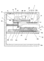
図2は、ネイルプリント装置のケース本体の内部構成を示す側断面図である。
図2に示すように、ケース本体2の内部にはネイルプリント装置1における印刷指固定手段を構成している印刷指固定部20、撮影手段を構成している撮影部30、印刷手段を構成している印刷部40及び制御手段を構成している制御部50(図8参照)が設置された制御基板51等が設けられている。
FIG. 2 is a side sectional view showing the internal configuration of the case main body of the nail printing apparatus.
As shown in FIG. 2, the case body 2 includes a printing finger fixing unit 20 constituting a printing finger fixing unit in the nail printing apparatus 1, a photographing unit 30 constituting a photographing unit, and a printing unit. A control board 51 on which a printing unit 40 and a control unit 50 (see FIG. 8) constituting a control unit are installed.

印刷指固定部20は、印刷しようとする爪部Tに対応する指(以下「印刷指」という。)U1を固定するものであり、ケース本体2の下部に設けられている。本実施形態においては、印刷指固定ユニット60(図3等参照)、指固定ユニット収容部20a、非印刷指挿入部20b及び掴み部20cによって印刷指固定部20が構成されており、印刷指U1の撮影や印刷は、印刷指固定ユニット60に印刷指U1が挿入され印刷指固定部20において印刷指U1が固定された状態で行われる。   The printing finger fixing unit 20 fixes a finger (hereinafter referred to as “printing finger”) U <b> 1 corresponding to the nail part T to be printed, and is provided at the lower part of the case body 2. In the present embodiment, the printing finger fixing unit 60 (see FIG. 3 and the like), the finger fixing unit housing portion 20a, the non-printing finger insertion portion 20b, and the grip portion 20c constitute the printing finger fixing portion 20, and the printing finger U1. The printing and printing are performed in a state where the printing finger U1 is inserted into the printing finger fixing unit 60 and the printing finger U1 is fixed in the printing finger fixing unit 20.

指固定ユニット収容部20aは印刷指U1を固定する印刷指固定ユニット60を収容するめための収容部である。指固定ユニット収容部20aの底面は、印刷指固定ユニット60を載置する指固定ユニット載置手段として機能する。
また、非印刷指挿入部20bは、印刷しようとする爪部Tに対応する指以外の指(図示せず。以下「非印刷指」という。)を挿入するめための挿入部である。
The finger fixing unit accommodating portion 20a is an accommodating portion for accommodating the printing finger fixing unit 60 that fixes the printing finger U1. The bottom surface of the finger fixing unit accommodating portion 20a functions as a finger fixing unit placing unit for placing the printing finger fixing unit 60 thereon.
The non-printing finger insertion part 20b is an insertion part for inserting a finger other than the finger corresponding to the nail part T to be printed (not shown; hereinafter referred to as “non-printing finger”).

また、掴み部20cは、指固定ユニット収容部20aに収容された印刷指固定ユニット60内に挿入された印刷指U1と、非印刷指挿入部20bに挿入された非印刷指とで挟持することが可能な部分である。本実施形態において、この掴み部20cは指固定ユニット収容部20aと非印刷指挿入部20bとを仕切る隔壁によって構成されている。
この掴み部(隔壁)20cの指挿入側端部の形状は特に限定されない。例えば、指固定ユニット収容部20aに収容された印刷指固定ユニット60及び非印刷指挿入部20bに印刷指U1及び非印刷指を深く挿入した際に、印刷指U1及び非印刷指の付け根が当接する部分に、指挿入方向の断面形状が円形等に形成された膨出部が設けられていてもよい。掴み部(隔壁)20cの指挿入側端部に膨出部を形成した場合には、印刷指U1を印刷指固定ユニット60内に挿入した状態で、印刷指U1と非印刷指とで掴み部(隔壁)20cを強く挟持することができ、好ましい。なお、膨出部の形状は、断面円形に限定されることなく、断面楕円形、断面多角形等の非円形であってもよい。
なお、上記非印刷指挿入部20b及び上記掴み部20cを設けなくてもよいが、これらを設けることにより、指固定ユニット収容部20aに収容された印刷指固定ユニット60及びこの印刷指固定ユニット60内に挿入されている印刷指U1をより安定させることができ、印刷指U1を固定するために極めて有効である。
Further, the grip portion 20c is sandwiched between the printing finger U1 inserted into the printing finger fixing unit 60 accommodated in the finger fixing unit housing portion 20a and the non-printing finger inserted into the non-printing finger insertion portion 20b. Is a possible part. In the present embodiment, the grip portion 20c is configured by a partition wall that partitions the finger fixing unit housing portion 20a and the non-printing finger insertion portion 20b.
The shape of the end part on the finger insertion side of the grip part (partition wall) 20c is not particularly limited. For example, when the printing finger U1 and the non-printing finger are inserted deeply into the printing finger fixing unit 60 and the non-printing finger insertion unit 20b accommodated in the finger fixing unit housing unit 20a, the bases of the printing finger U1 and the non-printing finger are applied. A bulging portion in which the cross-sectional shape in the finger insertion direction is formed in a circular shape or the like may be provided at the contact portion. When the bulging portion is formed at the finger insertion side end of the gripping portion (partition wall) 20c, the gripping portion between the printing finger U1 and the non-printing finger with the printing finger U1 inserted into the printing finger fixing unit 60. The (partition wall) 20c can be strongly held, which is preferable. The shape of the bulging portion is not limited to a circular cross section, and may be a non-circular shape such as an elliptical cross section or a polygonal cross section.
The non-printing finger insertion portion 20b and the grip portion 20c may not be provided, but by providing these, the printing finger fixing unit 60 accommodated in the finger fixing unit housing portion 20a and the printing finger fixing unit 60 are provided. The printing finger U1 inserted into the printing finger U1 can be further stabilized, and is extremely effective for fixing the printing finger U1.

ここで、指固定ユニット収容部20aに収容されている印刷指固定ユニット60について、図3から図7を参照しつつ具体的に説明する。
図3は、本実施形態における印刷指固定ユニット60の斜視図であり、図4は、印刷指固定ユニット60を上方(図2における上方)から見た平面図であり、図5は、図4の印刷指固定ユニット60に左手の人差し指から小指までの4指を挿入した状態を示した平面図である。また、図6は、図4のVI-VI線に沿う印刷指固定ユニット60の断面図であり、図7は、図5のVII-VII線に沿う印刷指固定ユニット60の断面図である。
Here, the printing finger fixing unit 60 accommodated in the finger fixing unit accommodating portion 20a will be specifically described with reference to FIGS.
3 is a perspective view of the printing finger fixing unit 60 in the present embodiment, FIG. 4 is a plan view of the printing finger fixing unit 60 as viewed from above (upward in FIG. 2), and FIG. It is the top view which showed the state which inserted 4 fingers from the index finger of the left hand to the little finger in the printing finger fixing unit 60 of FIG. 6 is a cross-sectional view of the printing finger fixing unit 60 along the line VI-VI in FIG. 4, and FIG. 7 is a cross-sectional view of the printing finger fixing unit 60 along the line VII-VII in FIG.

図3から図7に示すように、本実施形態では、印刷指固定ユニット60は、それぞれ1本の指を挿入可能に構成された4つの指挿入部材61と、この4つの指挿入部材61を収納するカバー部材62とを備えている。なお、本実施形態では印刷指固定ユニット60が4つの指挿入部材61を備えている場合を例として説明するが、印刷指固定ユニット60に備えられる指挿入部材61は4つに限定されない。例えば印刷指U1を1本ずつ印刷するネイルプリント装置1であれば、指挿入部材61が1つ設けられていればよい。また、印刷しようとする指の種類や数等に応じて印刷指固定ユニット60に収容される指挿入部材61を入れ替えて、その種類や数を変更できるようにしてもよい。   As shown in FIGS. 3 to 7, in this embodiment, the printing finger fixing unit 60 includes four finger insertion members 61 each configured to be capable of inserting one finger, and the four finger insertion members 61. And a cover member 62 for storage. In the present embodiment, the case where the printing finger fixing unit 60 includes four finger insertion members 61 will be described as an example. However, the number of finger insertion members 61 included in the printing finger fixing unit 60 is not limited to four. For example, in the case of the nail printing apparatus 1 that prints the printing fingers U1 one by one, one finger insertion member 61 may be provided. Further, the finger insertion member 61 accommodated in the printing finger fixing unit 60 may be exchanged according to the type and number of fingers to be printed, so that the type and number can be changed.

各指挿入部材61は、一端側に開口する断面コ字状の部材であり(図6等参照)、開口側が下(図2において下側)になるようにカバー部材62に収容されている。
指挿入部材61の開口側に対向する面(図2において上側の面)には爪部露出窓611が形成されており、指挿入部材61に印刷指U1が挿入された際には、この爪部露出窓611から印刷指U1の爪部Tが露出するようになっている。爪部露出窓611はネイルプリント装置1を利用することが想定されるユーザの各種の指や爪部の大きさ、形状に合うように、大きめに形成されていることが望ましい。
なお、爪部露出窓611は印刷指U1の爪部Tを露出させることができるものであればよく、爪部露出窓611の設けられる位置、大きさ、形状等は図示例に限定されない。
Each finger insertion member 61 is a member having a U-shaped cross section that opens to one end side (see FIG. 6 and the like), and is accommodated in the cover member 62 so that the opening side is downward (lower side in FIG. 2).
A nail part exposure window 611 is formed on the surface (upper surface in FIG. 2) facing the opening side of the finger insertion member 61. When the printing finger U1 is inserted into the finger insertion member 61, this nail is exposed. The nail part T of the printing finger U1 is exposed from the part exposure window 611. It is desirable that the nail portion exposure window 611 is formed to be large so as to match the size and shape of various fingers and nail portions of the user who are assumed to use the nail printing apparatus 1.
The nail part exposure window 611 may be any one that can expose the nail part T of the printing finger U1, and the position, size, shape, and the like of the nail part exposure window 611 are not limited to the illustrated example.

指挿入部材61の開口側に対向する面(図2において上側の面)であって爪部露出窓611よりも指挿入方向A(図4等参照)の手前側は、印刷指U1を挿入した際に爪部Tの生え際近傍を上方から押さえる指押え部612となっている。   The printing finger U1 is inserted on the front side of the finger insertion member 61 (the upper surface in FIG. 2) and in the finger insertion direction A (see FIG. 4 and the like) from the nail portion exposure window 611. At this time, a finger press portion 612 that presses the vicinity of the hairline of the claw portion T from above is provided.

各指挿入部材61の内側であって爪部露出窓611よりも指挿入方向A(図4等参照)の奥側には、指挿入部材61に印刷指U1が挿入された際に印刷指U1の先端部が突き当たる突き当て部材613が設けられている。本実施形態において、突き当て部材613は、爪部露出窓611における指挿入方向Aの奥側の端縁から下方(すなわち、指挿入部材61の開口側)に向かってほぼ垂直に立設されている板状の部材である。
なお、突き当て部材613は、各指挿入部材61内に挿入された印刷指U1の先端部が突き当て部材613に突き当てられた際に印刷指U1の爪部が爪部露出窓611から露出する位置に設けられていればよく、突き当て部材613の形状や大きさ、設けられる位置等は、図示例に限定されない。
When the printing finger U1 is inserted into the finger insertion member 61 inside the finger insertion member 61 and behind the nail portion exposure window 611 in the finger insertion direction A (see FIG. 4 and the like), the printing finger U1 The abutting member 613 with which the front-end | tip part abuts is provided. In the present embodiment, the abutting member 613 is erected substantially vertically from the edge on the back side in the finger insertion direction A in the nail portion exposure window 611 toward the lower side (that is, the opening side of the finger insertion member 61). It is a plate-shaped member.
The abutting member 613 is configured such that the nail portion of the printing finger U1 is exposed from the nail portion exposure window 611 when the tip of the printing finger U1 inserted into each finger insertion member 61 is abutted against the abutting member 613. The shape and size of the abutting member 613, the position provided, and the like are not limited to the illustrated example.

カバー部材62は、一端に開口部を有する箱状の部材であり、図3に示すように、本実施形態では、この開口部内に4つの指挿入部材61が配置されている。印刷指固定ユニット60は、この開口部が指挿入方向Aの手前側に来るように指固定ユニット収容部20aに収容される。   The cover member 62 is a box-shaped member having an opening at one end. As shown in FIG. 3, in this embodiment, four finger insertion members 61 are arranged in the opening. The printing finger fixing unit 60 is accommodated in the finger fixing unit accommodating portion 20a so that the opening is on the near side in the finger insertion direction A.

カバー部材62の上面(図2、図6等において上側の面)には、指挿入部材61の爪部露出窓611から露出している印刷指U1の爪部Tを露出させる爪部露出用開口部621が設けられている。
爪部露出用開口部621の幅方向(図6等において横方向)における長さ寸法Xは、図7に示すように、カバー部材62内に収容される4つの指挿入部材61の爪部露出窓611を全て露出させることができるように、カバー部材62内の最も左端に位置する指挿入部材61の爪部露出窓611の左側辺からカバー部材62内の最も右端に位置する指挿入部材61の爪部露出窓611の右側辺までの長さ以上の長さ寸法となっている。また、爪部露出用開口部621の指挿入方向A(図4及び図5において縦方向)における長さ寸法Yは、図7に示すように、爪部Tの位置が最も指挿入方向Aの手前側に位置する印刷指U1(例えば、小指)の爪部Tが露出している爪部露出窓611の手前側の端部から、爪部Tの位置が最も指挿入方向Aの奥側に位置する印刷指U1(例えば、中指)の爪部Tが露出している爪部露出窓611の奥側の端部までの長さ以上の長さ寸法となっている。
On the upper surface of the cover member 62 (the upper surface in FIGS. 2 and 6, etc.), a nail portion exposure opening for exposing the nail portion T of the printing finger U1 exposed from the nail portion exposure window 611 of the finger insertion member 61. A part 621 is provided.
The length dimension X in the width direction (lateral direction in FIG. 6 etc.) of the nail portion opening 621 is the nail portion exposure of the four finger insertion members 61 accommodated in the cover member 62 as shown in FIG. The finger insertion member 61 located at the rightmost end in the cover member 62 from the left side of the nail portion exposure window 611 of the finger insertion member 61 located at the leftmost end in the cover member 62 so that the window 611 can be fully exposed. The claw part exposure window 611 is longer than the right side of the window 611. Further, the length Y in the finger insertion direction A (vertical direction in FIGS. 4 and 5) of the opening 621 for nail part exposure is such that the position of the nail T is the most in the finger insertion direction A as shown in FIG. From the front end of the nail portion exposure window 611 where the nail portion T of the printing finger U1 (for example, the little finger) located on the near side is exposed, the position of the nail portion T is farthest in the finger insertion direction A. The length dimension is equal to or longer than the length of the nail portion exposure window 611 where the nail portion T of the printing finger U1 (for example, the middle finger) is exposed.

図6に示すように、カバー部材62の底部(図2、図6等において下側)上には、指挿入部材61の各側壁の下端を受ける一対のガイド溝622が4つの指挿入部材61に対応する位置にそれぞれ指挿入方向Aに沿って形成されている。ガイド溝622は、指挿入部材61内に印刷指U1が挿入されて指挿入部材61が印刷指U1によって奥側に押し込まれた際に指挿入部材61を印刷指U1の挿入方向Aに案内するガイド部である。   As shown in FIG. 6, a pair of guide grooves 622 that receive the lower ends of the respective side walls of the finger insertion member 61 are provided on the bottom (lower side in FIGS. 2, 6, etc.) of the cover member 62. Are formed along the finger insertion direction A, respectively. The guide groove 622 guides the finger insertion member 61 in the insertion direction A of the printing finger U1 when the printing finger U1 is inserted into the finger insertion member 61 and the finger insertion member 61 is pushed back by the printing finger U1. It is a guide part.

また、カバー部材62の底部であって各指挿入部材61の各側壁を受けるガイド溝622の間であって各指挿入部材61の下方には、それぞれ凹部623が設けられている。この凹部623内には、指挿入部材61内に挿入される印刷指U1を下側から保持する指置き部材624と、この指置き部材624を下側から押し上げる押し上げ機構625とがそれぞれ設けられている。
指置き部材624は、例えば樹脂等の弾性部材であり、印刷指U1を安定的に保持することができるようになっている。なお、指置き部材624は、印刷指U1を安定的に保持することができるものであればよく、指置き部材624を形成する材料やその形状等は特に限定されない。
押し上げ機構625は、例えば油圧や空気圧によって下側から指置き部材624を押し上げるものである。押し上げ機構625は、後述する制御部50により、指置き部材624を、その下側半分ほどが凹部623内に収容される位置から、指挿入部材61に挿入された印刷指U1の上側であって爪部Tの生え際近傍が指挿入部材61の上面の指押え部612に突き当てられる位置まで上下させるように制御される。なお、押し上げ機構625は、指置き部材624を上下させることのできるものであればよく、その構成はここに例示したものに限定されない。例えば指置き部材624を下側から支持する板等を設けて、この板等をユーザが手動で押し上げることにより指置き部材624を押し上げる構成としてもよい。この場合には、ユーザが板等の押し上げ状態を手動で解除することにより指置き部材624の位置を元の位置まで下げるようにする。
Further, a recess 623 is provided at the bottom of the cover member 62 and between the guide grooves 622 that receive the side walls of the finger insertion members 61 and below the finger insertion members 61. In the recess 623, a finger placement member 624 for holding the printing finger U1 inserted into the finger insertion member 61 from the lower side and a push-up mechanism 625 for pushing up the finger placement member 624 from the lower side are provided. Yes.
The finger placement member 624 is an elastic member such as resin, for example, and can hold the printing finger U1 stably. The finger placement member 624 only needs to be capable of stably holding the printing finger U1, and the material, the shape, and the like of the finger placement member 624 are not particularly limited.
The push-up mechanism 625 pushes up the finger placement member 624 from below by, for example, hydraulic pressure or air pressure. The push-up mechanism 625 is arranged on the upper side of the print finger U1 inserted into the finger insertion member 61 from the position where the lower half of the finger placement member 624 is accommodated in the recess 623 by the control unit 50 described later. Control is performed so that the vicinity of the hairline of the nail portion T is moved up and down to a position where it is abutted against the finger pressing portion 612 on the upper surface of the finger insertion member 61. The push-up mechanism 625 may be any mechanism that can move the finger placing member 624 up and down, and the configuration is not limited to the one exemplified here. For example, a plate or the like that supports the finger placement member 624 from the lower side may be provided, and the finger placement member 624 may be pushed up by manually pushing up the plate or the like. In this case, the position of the finger placing member 624 is lowered to the original position by manually releasing the pushed-up state of the plate or the like by the user.

カバー部材62内部の指挿入方向Aの奥側の面と各指挿入部材61との間には、位置復帰用バネ63がそれぞれ配置されている。位置復帰用バネ63は、指挿入部材61の内部に印刷指U1が挿入され、指挿入方向Aの奥側にスライド移動した後に印刷指U1が引き抜かれた際、指挿入部材61を元の初期位置(図4に示す指挿入部材61の位置)まで押し戻す位置復帰手段である。なお、指挿入部材61を元の位置に戻すための位置復帰手段はバネに限定されず、他の手段を用いてもよい。
本実施形態において、位置復帰用バネ63の一端は、突き当て部材613における印刷指U1が突き当てられる側とは反対の面に固定されており、位置復帰用バネ63の他端は、カバー部材62における指挿入方向Aの奥側の面に当接している。なお、位置復帰用バネ63は、カバー部材62と指挿入部材61との間に介在していればよく、その固定される位置はここに例示したものに限定されない。
なお、カバー部材62又は各指挿入部材61の一端には、位置復帰用バネ63によって指挿入方向Aの奥側から手前側に指挿入部材が押し戻された際に指挿入部材がカバー部材62の開口部から飛び出し、抜け落ちることを防止するための図示しないストッパが設けられている。なお、位置復帰用バネ63の他端を、カバー部材62における指挿入方向Aの奥側の面に固定する構成としてもよい。また、例えば指固定ユニット収容部20aの開口部の寸法を印刷指固定ユニット60の指挿入部材61の断面形状の寸法よりも小さくすることにより、指固定ユニット収容部20aの開口部から印刷指固定ユニット60の指挿入部材61が飛び出さないように構成してもよい。
Position return springs 63 are arranged between the inner surface of the cover member 62 in the finger insertion direction A and each finger insertion member 61. When the printing finger U1 is inserted into the finger insertion member 61 and slid to the back side in the finger insertion direction A and then the printing finger U1 is pulled out, the position return spring 63 moves the finger insertion member 61 to the original initial position. Position return means for pushing back to the position (position of the finger insertion member 61 shown in FIG. 4). Note that the position return means for returning the finger insertion member 61 to the original position is not limited to a spring, and other means may be used.
In the present embodiment, one end of the position return spring 63 is fixed to the surface of the abutting member 613 opposite to the side against which the printing finger U1 is abutted, and the other end of the position restoring spring 63 is the cover member. 62 is in contact with the inner surface of the finger insertion direction A. The position return spring 63 only needs to be interposed between the cover member 62 and the finger insertion member 61, and the position to be fixed is not limited to the one illustrated here.
It should be noted that the finger insertion member is attached to one end of the cover member 62 or each finger insertion member 61 when the finger insertion member is pushed back from the back side to the front side in the finger insertion direction A by the position return spring 63. A stopper (not shown) is provided for preventing jumping out from the opening and falling off. The other end of the position return spring 63 may be fixed to the inner surface of the cover member 62 in the finger insertion direction A. In addition, for example, by making the size of the opening of the finger fixing unit accommodating portion 20a smaller than the size of the cross-sectional shape of the finger insertion member 61 of the printing finger fixing unit 60, the printing finger is fixed from the opening of the finger fixing unit accommodating portion 20a. You may comprise so that the finger insertion member 61 of the unit 60 may not jump out.

本実施形態において、印刷指U1をその先端が突き当て部材613に突き当たるまで指挿入部材61の内部に挿入すると、突き当て部材613よりも指挿入方向Aの手前側に設けられている爪部露出窓611から爪部Tが露出するとともに、爪部露出窓611よりも指挿入方向Aの手前側に設けられている指押え部612によって爪部Tの生え際近傍が覆われるようになっている。
また、指挿入部材61は、印刷指U1の先端が突き当て部材613に突き当てられると、指挿入方向Aに向かってカバー部材62の奥側に押し込まれる。これにより、各指挿入部材61は、それぞれ指挿入部材61に挿入された印刷指U1の長さに応じて、位置復帰用バネ63を押し縮めながら、指挿入方向Aの奥側にスライド移動する。
そして、印刷指U1と非印刷指との付け根が掴み分20cの端部に当接するまで深く印刷指U1を挿入した状態において、最も長い印刷指U1から最も短い印刷指U1までのすべての印刷指U1の爪部Tが爪部露出窓611を通してカバー部材62の爪部露出用開口部621から露出するとともに、押し上げ機構625により指置き部材624が押し上げられることにより、爪部Tの生え際近傍が指押え部612によって押さえられ、爪部Tが上側に浮き上がるのを防止するようになっている。
In the present embodiment, when the printing finger U1 is inserted into the finger insertion member 61 until the tip of the printing finger U1 comes into contact with the abutting member 613, the nail portion exposed on the near side in the finger insertion direction A with respect to the abutting member 613 is exposed. The nail portion T is exposed from the window 611, and the vicinity of the hairline of the nail portion T is covered by a finger presser portion 612 provided on the near side in the finger insertion direction A from the nail portion exposure window 611.
The finger insertion member 61 is pushed toward the back side of the cover member 62 in the finger insertion direction A when the tip of the printing finger U1 is abutted against the abutting member 613. As a result, each finger insertion member 61 slides to the back side in the finger insertion direction A while pressing and shrinking the position return spring 63 according to the length of the printing finger U1 inserted into the finger insertion member 61. .
In the state where the printing finger U1 is inserted deeply until the base of the printing finger U1 and the non-printing finger comes into contact with the end of the grip 20c, all the printing fingers from the longest printing finger U1 to the shortest printing finger U1. The claw portion T of U1 is exposed from the claw portion exposure opening 621 of the cover member 62 through the claw portion exposure window 611, and the finger placement member 624 is pushed up by the push-up mechanism 625, so that the vicinity of the hairline of the claw portion T is fingered. The claw T is prevented from being lifted upward by being pressed by the presser 612.

図2に示すように、撮影部30は、ケース本体2の上部であって、印刷指固定ユニット60の上方に設けられている。
撮影部30は、ドライバーを内蔵した200万画素程度以上の画素を有するカメラ31と、このカメラ31を囲むように配置された白色LED等の照明灯32とを備えている。撮影部30は、このカメラ31及び照明灯32を備えて構成されている。
この撮影部30は、印刷指固定ユニット60に固定された印刷指U1を照明灯32によって照明し、カメラ31によってその印刷指U1を撮影して、指爪画像を得るものであり、本実施形態では、撮影部30は、印刷指固定ユニット60に挿入されて印刷指固定部20に固定されている印刷指U1を撮影して指爪画像を取得する撮影手段として機能する。
この撮影部30は、後述する制御部50に接続され、該制御部50によって制御されるようになっている。
As shown in FIG. 2, the photographing unit 30 is provided above the case body 2 and above the printing finger fixing unit 60.
The photographing unit 30 includes a camera 31 having a driver and a pixel of about 2 million pixels or more, and an illumination lamp 32 such as a white LED arranged so as to surround the camera 31. The photographing unit 30 includes the camera 31 and the illumination lamp 32.
The photographing unit 30 illuminates a printing finger U1 fixed to the printing finger fixing unit 60 with an illumination lamp 32, and photographs the printing finger U1 with a camera 31, thereby obtaining a fingernail image. Then, the imaging unit 30 functions as an imaging unit that acquires the fingernail image by imaging the printing finger U1 inserted into the printing finger fixing unit 60 and fixed to the printing finger fixing unit 20.
The photographing unit 30 is connected to a control unit 50 described later, and is controlled by the control unit 50.

また、印刷部40は、印刷指固定部20の印刷指固定ユニット60に固定されている印刷指U1の爪部Tにそれぞれ印刷を施す印刷手段であり、ケース本体2の上部であって、印刷指固定ユニット60の上方に設けられている。
すなわち、ケース本体2の両側板には、2本のガイドロッド41が平行に架設されている。このガイドロッド41には、主キャリッジ42が摺動自在に設置されている。また、図2に示すように、主キャリッジ42の前壁42aおよび後壁42bには2本のガイドロッド44が平行に架設されている。このガイドロッド44には、副キャリッジ45が摺動自在に設置されている。この副キャリッジ45の下面中央部には、印刷ヘッド46が搭載されている。なお、ガイドロッド41、44は2本に限定されず、1本でもよいが、主キャリッジ42、副キャリッジ45、及び印刷ヘッド46を安定的に支持し、円滑に移動可能とするために2本以上のガイドロッド41、44が設けられていることが好ましい。
本実施形態において、この印刷ヘッド46は、インクを微滴化し、被印刷媒体である爪部Tに対し直接に吹き付けて印刷を行うインクジェット方式の印刷ヘッドである。なお、印刷ヘッド46の記録方式はインクジェット方式に限定されない。
The printing unit 40 is a printing unit that performs printing on each of the nail portions T of the printing finger U1 fixed to the printing finger fixing unit 60 of the printing finger fixing unit 20. It is provided above the finger fixing unit 60.
That is, two guide rods 41 are installed in parallel on both side plates of the case body 2. A main carriage 42 is slidably installed on the guide rod 41. As shown in FIG. 2, two guide rods 44 are installed in parallel on the front wall 42a and the rear wall 42b of the main carriage 42. A sub carriage 45 is slidably installed on the guide rod 44. A print head 46 is mounted at the center of the lower surface of the sub carriage 45. The guide rods 41 and 44 are not limited to two, but may be one. However, two guide rods 41 and 44 are provided in order to stably support the main carriage 42, the sub-carriage 45, and the print head 46 so that they can move smoothly. The above guide rods 41 and 44 are preferably provided.
In the present embodiment, the print head 46 is an ink jet type print head that performs printing by atomizing ink and spraying it directly onto the nail portion T that is a printing medium. The recording method of the print head 46 is not limited to the ink jet method.

主キャリッジ42は動力伝達手段(図示せず)を介して第1モータ43に連結され、第1モータ43の正逆回転によって、ガイドロッド41に沿って左右方向に移動ように構成されている。また、副キャリッジ45は動力伝達手段(図示せず)を介して第2モータ47に連結され、第2モータ47の正逆回転によって、ガイドロッド44に沿って前後方向に移動するように構成されている。
本実施形態では、印刷ヘッド46の印刷可能領域は、カバー部材62の爪部露出用開口部621に対応する範囲内(すなわち、図5における横方向X、縦方向Yの範囲内)となっており、この範囲内において爪部露出用開口部621から露出している爪部Tに対して印刷を施すことができるようになっている。
The main carriage 42 is connected to the first motor 43 via a power transmission means (not shown), and is configured to move in the left-right direction along the guide rod 41 by forward and reverse rotation of the first motor 43. The sub-carriage 45 is connected to the second motor 47 via power transmission means (not shown), and is configured to move in the front-rear direction along the guide rod 44 by forward and reverse rotation of the second motor 47. ing.
In the present embodiment, the printable area of the print head 46 is within a range corresponding to the claw part opening 621 of the cover member 62 (that is, within the range of the horizontal direction X and the vertical direction Y in FIG. 5). In this range, the nail portion T exposed from the nail portion opening 621 can be printed.

また、ケース本体2内には、印刷ヘッド46にインクを供給するための図示しないインクカートリッジが設けられている。インクカートリッジは、図示しないインク供給管を介して印刷ヘッド46と接続されており、適宜印刷ヘッド46にインクを供給するようになっている。なお、印刷ヘッド46自体にインクカートリッジを搭載する構成としてもよい。   In addition, an ink cartridge (not shown) for supplying ink to the print head 46 is provided in the case body 2. The ink cartridge is connected to the print head 46 via an ink supply pipe (not shown), and supplies ink to the print head 46 as appropriate. Note that an ink cartridge may be mounted on the print head 46 itself.

印刷部40は、これらガイドロッド41、主キャリッジ42、第1モータ43、ガイドロッド44、副キャリッジ45、印刷ヘッド46、第2モータ47及びインクカートリッジ等を備えて構成されている。この印刷部40の第1モータ43、印刷ヘッド46、第2モータ47は、後述する制御部50に接続され、該制御部50によって制御されるようになっている。   The printing unit 40 includes the guide rod 41, the main carriage 42, the first motor 43, the guide rod 44, the sub carriage 45, the print head 46, the second motor 47, an ink cartridge, and the like. The first motor 43, the print head 46, and the second motor 47 of the printing unit 40 are connected to a control unit 50, which will be described later, and are controlled by the control unit 50.

操作部12は、ユーザが各種入力を行うための入力手段である。
操作部12には、例えば、ネイルプリント装置1の電源をONする電源スイッチ釦、印刷処理を開始させる印刷開始スイッチ釦、動作を停止させる停止スイッチ釦、その他各種の入力を行うための各種の操作釦121が配置されている。
The operation unit 12 is input means for the user to make various inputs.
The operation unit 12 includes, for example, a power switch button for turning on the power of the nail printing apparatus 1, a print start switch button for starting the printing process, a stop switch button for stopping the operation, and various other operations for performing various inputs. A button 121 is arranged.

また、表示部13は、例えば液晶パネル(液晶ディスプレイ(LCD:Liquid Crystal Display))等で構成された表示手段である。
なお、表示部13の表面に、タッチパネルが一体的に構成されていてもよい。この場合には、図示しないスタイラスペンや指先等によるタッチ操作により、表示部13の表面をタッチすることによっても各種の入力を行うことができるように構成される。
The display unit 13 is a display unit configured with, for example, a liquid crystal panel (liquid crystal display (LCD)).
A touch panel may be integrally formed on the surface of the display unit 13. In this case, various inputs can be performed by touching the surface of the display unit 13 by a touch operation with a stylus pen or a fingertip (not shown).

表示部13には、例えば、印刷指U1を撮影した指爪画像やその中の爪部Tの領域、印刷指U1の爪部Tの領域に印刷すべきネイル画像パターン、デザイン確認用のサムネイル画像等が表示されるようになっている。
また、本実施形態では、印刷指固定ユニット60に挿入されて印刷指固定部20に固定されている印刷指U1について撮影部30により指爪画像が撮影されると、撮影された指爪画像、印刷指固定ユニット60に印刷指U1が挿入されている状態(例えば、図5に示す状態)を示す画像を表示部13に表示させるようになっており、表示部13は、撮影部30で撮影された指爪画像を表示させる表示手段として機能する。ユーザは、表示部13に表示されたこの画像を確認することによって、自分の印刷指U1が正しい位置に挿入されているか否かを目視にて確認することが可能となる。
The display unit 13 includes, for example, a fingernail image obtained by photographing the printing finger U1, a region of the nail portion T therein, a nail image pattern to be printed on the region of the nail portion T of the printing finger U1, and a thumbnail image for design confirmation. Etc. are displayed.
Further, in the present embodiment, when a fingernail image is photographed by the photographing unit 30 with respect to the printing finger U1 inserted into the printing finger fixing unit 60 and fixed to the printing finger fixing unit 20, the photographed fingernail image, An image showing a state (for example, the state shown in FIG. 5) in which the printing finger U1 is inserted into the printing finger fixing unit 60 is displayed on the display unit 13, and the display unit 13 is photographed by the photographing unit 30. It functions as a display means for displaying the fingernail image. By checking this image displayed on the display unit 13, the user can visually check whether or not his / her printing finger U1 is inserted at the correct position.

次に、図8を参照しつつ、本実施形態の制御構成について説明する。図8は、本実施形態における制御構成を示す要部ブロック図である。
制御部50は、例えばケース本体2の上部に配置された制御基板51上に実装されており、図示しないCPU(Central Processing Unit)、ROM(Read Only Memory)、R
AM(Random Access Memory)等を備えるコンピュータである。ROM等の記憶手段には
印刷すべきネイル画像パターン等のデータや印刷処理を行うための印刷プログラム等の各種プログラムが格納され、制御部50はこれらのプログラムを実行してネイルプリント装置1の各部を制御するようになっている。
Next, the control configuration of the present embodiment will be described with reference to FIG. FIG. 8 is a principal block diagram showing a control configuration in the present embodiment.
The control unit 50 is mounted on, for example, a control board 51 disposed on the upper portion of the case body 2, and includes a CPU (Central Processing Unit), a ROM (Read Only Memory), an R (not shown), and an R.
A computer having an AM (Random Access Memory) or the like. The storage means such as a ROM stores data such as nail image patterns to be printed and various programs such as a printing program for performing printing processing, and the control unit 50 executes these programs to execute each unit of the nail printing apparatus 1. Is to control.

本実施形態において、制御部50には、印刷指U1が載置された指置き部材624を上方に押し上げる指押し上げ機構625、撮影部30を構成するカメラ31及び照明灯32、印刷部40を構成する第1モータ43、第2モータ47及び印刷ヘッド46が接続されており、制御部50は、これらの動作を制御するようになっている。
また、制御部50には、ユーザによって操作部12の操作釦121から入力された指示が送られるようになっており、制御部50は、この指示信号に基づいて各種制御を行う。
また、制御部50は、表示部13を制御して、表示部13に各種確認画面等を表示させるようになっている。
In the present embodiment, the control unit 50 includes a finger push-up mechanism 625 that pushes up the finger placing member 624 on which the printing finger U1 is placed, a camera 31 and an illumination lamp 32 that constitute the photographing unit 30, and a printing unit 40. The first motor 43, the second motor 47, and the print head 46 are connected to each other, and the control unit 50 controls these operations.
In addition, instructions input from the operation buttons 121 of the operation unit 12 by the user are sent to the control unit 50, and the control unit 50 performs various controls based on the instruction signals.
Further, the control unit 50 controls the display unit 13 to display various confirmation screens on the display unit 13.

次に、図4から図7及び図9(A)から図9(C)を参照しつつ、本実施形態における作用について説明する。   Next, the operation of this embodiment will be described with reference to FIGS. 4 to 7 and FIGS. 9A to 9C.

印刷指U1の爪部Tへの印刷を行う場合、ユーザはまず、操作釦121を操作してネイルプリント装置1の電源をONとし、印刷指U1の爪部Tに印刷したいネイル画像パターン(デザイン)を選択する。選択されたネイル画像パターンは、表示部13にデザイン確認用のサムネイル画像として表示されることが好ましい。   When performing printing on the nail portion T of the printing finger U1, the user first operates the operation button 121 to turn on the power of the nail printing apparatus 1, and the nail image pattern (design) to be printed on the nail portion T of the printing finger U1. ) Is selected. The selected nail image pattern is preferably displayed on the display unit 13 as a thumbnail image for design confirmation.

ネイル画像パターンを選択すると、ユーザは、印刷指固定部20の印刷指固定ユニット60内に印刷指U1を挿入する。
具体的には、例えば、左手の親指以外の4本の指(人差し指、中指、薬指及び小指)が印刷指U1となる場合、図4に示すように、ユーザは印刷指固定ユニット60の左端の指挿入部材61に小指、その右隣の指挿入部材61に薬指、さらにその右隣の指挿入部材61に中指、右端の指挿入部材61に人差し指を挿入するというように、4つの指挿入部材61にそれぞれ1本ずつ印刷指U1を挿入する。また、非印刷指挿入部20bに非印刷指である親指を挿入する。
When the nail image pattern is selected, the user inserts the printing finger U1 into the printing finger fixing unit 60 of the printing finger fixing unit 20.
Specifically, for example, when four fingers other than the thumb of the left hand (index finger, middle finger, ring finger, and little finger) are the print fingers U1, the user can move the left end of the print finger fixing unit 60 as shown in FIG. Four finger insertion members, such as a little finger in the finger insertion member 61, a ring finger in the right finger insertion member 61, a middle finger in the right finger insertion member 61, and an index finger in the right finger insertion member 61 One print finger U1 is inserted into each 61. Further, a thumb that is a non-printing finger is inserted into the non-printing finger insertion portion 20b.

図4のように、人差し指から小指までの4指をそれぞれ指挿入部材61に挿入する場合(図9(A)参照)、ユーザが印刷指U1及び非印刷指の付け根が掴み部20cの端部に当接する位置まで深く各印刷指U1を挿入すると、図5に示すように、4指のうち最も長い指(例えば、中指)が挿入された指挿入部材61は、印刷指U1の先端が突き当て部材613に突き当てられることにより位置復帰用バネ63を押し縮めながら指挿入方向Aの奥側に押し込まれ、指挿入方向Aに沿って大きくスライド移動する(図9(B)参照)。これに対して、4指のうち最も短い指(例えば、小指)が挿入された指挿入部材61は、印刷指の先端が突き当て部材613に突き当てられても指挿入部材61はほとんど奥側に押し込まれず、スライド移動しない。これにより、各指挿入部材61は、図5に示すように、挿入されている各印刷指U1の長さに応じた位置で停止する。
各指挿入部材61のスライド移動が停止すると、制御部50は押し上げ機構625を制御して、指置き部材624上に保持された印刷指U1を下側から押し上げ、印刷指U1の上面を指挿入部材61の上側の面の裏側(下側)に当接させる(図7及び図9(C)参照)。これにより、各印刷指U1は、それぞれ指挿入部材の爪部露出窓611から爪部Tが露出するとともに、爪部Tの生え際付近が指押え部612により上から押さえられて爪部T等が上側に上がらないように抑制された状態で固定される。
また、このとき、図5に示すように、すべての指挿入部材61の爪部露出窓611はカバー部材62の爪部露出用開口部621に対応する範囲内に位置しており、指挿入部材61に挿入されている印刷指U1の爪部Tが爪部露出用開口部621から露出する。
As shown in FIG. 4, when four fingers from the index finger to the little finger are each inserted into the finger insertion member 61 (see FIG. 9A), the base of the printing finger U1 and the non-printing finger is the end of the grip portion 20c. When each printing finger U1 is inserted deeply to a position where it comes into contact with the finger, the finger insertion member 61 into which the longest finger (for example, the middle finger) among the four fingers is inserted, as shown in FIG. By being abutted against the abutting member 613, the position return spring 63 is pushed and contracted to be pushed into the back side in the finger insertion direction A, and slides greatly along the finger insertion direction A (see FIG. 9B). On the other hand, the finger insertion member 61 into which the shortest finger (for example, the little finger) among the four fingers is inserted has the finger insertion member 61 almost on the back side even when the tip of the printing finger is abutted against the abutting member 613. Is not pushed in and does not move. As a result, each finger insertion member 61 stops at a position corresponding to the length of each inserted printing finger U1 as shown in FIG.
When the sliding movement of each finger insertion member 61 stops, the control unit 50 controls the push-up mechanism 625 to push up the printing finger U1 held on the finger placing member 624 from the lower side and insert the upper surface of the printing finger U1 with the finger. It is made to contact | abut to the back side (lower side) of the upper surface of the member 61 (refer FIG.7 and FIG.9 (C)). As a result, each printing finger U1 has its nail portion T exposed from the nail portion exposure window 611 of the finger insertion member, and the vicinity of the nail portion T is pressed from above by the finger press portion 612 so that the nail portion T and the like are formed. It is fixed in a restrained state so as not to rise upward.
At this time, as shown in FIG. 5, the nail portion exposure windows 611 of all the finger insertion members 61 are located within a range corresponding to the nail portion exposure openings 621 of the cover member 62, and the finger insertion members The nail part T of the printing finger U1 inserted in 61 is exposed from the opening part 621 for nail part exposure.

印刷指U1が上記のように印刷指固定部20に固定されると、印刷指固定部20に固定された印刷指U1を撮影部30により撮影し、指爪画像を取得する。そして、取得された画像は表示部13に表示され、ユーザは表示部13に表示された画像を目視することにより、印刷指U1が正しい位置に挿入されているかを確認する。   When the printing finger U1 is fixed to the printing finger fixing unit 20 as described above, the printing finger U1 fixed to the printing finger fixing unit 20 is imaged by the imaging unit 30, and a fingernail image is acquired. The acquired image is displayed on the display unit 13, and the user visually checks the image displayed on the display unit 13 to confirm whether the printing finger U1 is inserted at the correct position.

印刷指U1が正しい位置に挿入されている場合には、印刷部40が作動され、指挿入部材61に挿入されている各印刷指U1の爪部Tに選択されたネイル画像パターン(デザイン)が印刷される。   When the printing finger U1 is inserted at the correct position, the printing unit 40 is activated, and the selected nail image pattern (design) is applied to the nail portion T of each printing finger U1 inserted into the finger insertion member 61. Printed.

印刷処理が完了すると、制御部50は指押し上げ機構625を動作させて指置き部材624を元の位置まで戻す。そして、ユーザが指挿入部材61から印刷指U1を引き抜くと、位置復帰用バネ63によって指挿入部材61がもとの位置まで押し戻される。   When the printing process is completed, the control unit 50 operates the finger push-up mechanism 625 to return the finger placing member 624 to the original position. When the user pulls out the printing finger U1 from the finger insertion member 61, the finger insertion member 61 is pushed back to the original position by the position return spring 63.

以上のように、本実施形態によれば、爪部Tを露出させる爪部露出窓611と爪部Tの生え際近傍を上方から押さえる指押え部612と印刷指U1を挿入した際に印刷指U1の先端部が突き当たる突き当て部材613とを備え、印刷指U1を挿入した際に印刷指U1の長さに応じて指挿入方向Aに沿ってスライド移動する指挿入部材61に印刷指U1を挿入することにより印刷指U1の固定を行う。このため、どのような長さの指が印刷指U1として挿入された場合でも印刷指U1の長さに応じた位置まで指挿入部材61がスライド移動し、爪部露出窓611から爪部Tを露出させるとともに、指押え部612によって爪部Tの生え際近傍を上方から押さえることができ、できるだけ印刷ヘッド46に近い位置に印刷指U1の爪部Tを固定しつつ印刷指U1が上側に反ること等を防止することができる。これにより、指挿入部材61に印刷指U1を挿入するという簡易な手法により、近距離から正確にインクを着弾させて精緻な印刷を行うことができるとともに、印刷ヘッド46と印刷指U1との接触による印刷ヘッド46の破損、印刷指U1へのインク等の付着を確実に防ぐことができる。また、爪部Tの生え際近傍が指押え部612によって覆われた状態となることから、爪部Tの生え際近傍に印刷ヘッド46から飛散したインクが付着することを防止することができる。
また、印刷指固定部20の印刷指固定ユニット60に設けられるカバー部材62に、指挿入部材61内に印刷指U1が挿入された際に指挿入部材61を印刷指U1の指挿入方向Aに案内するガイド溝622を備えている。このため、印刷指U1が突き当て部材613に突き当たると、印刷指U1の先端で押しこむことにより指挿入部材61を円滑に指挿入方向Aの奥側にスライド移動させることができる。
また、指挿入部材61の下方には、樹脂等で形成された指置き部材624が配置されているため、指挿入部材61に挿入された印刷指U1を下方から安定的に保持することができ、印刷指U1を挿入するユーザの負担を軽減することができる。
また、指置き部材624を下方から押し上げる押し上げ機構625を備えているため、適度な高さまでユーザが自分で指置き部材624を押し上げる必要がなく、簡易に印刷指U1を適切な位置(すなわち、爪部Tと印刷ヘッド46との位置関係(距離等)において適切な位置)に固定することができる。
また、本実施形態では、印刷指固定部20に固定されている印刷指U1を撮影部30により撮影して指爪画像を取得し、この画像を表示部13に表示させるため、ユーザは表示部13の画面を確認するだけで、自分の指が適切な位置に配置されているか否かを簡易に確認することができる。
As described above, according to the present embodiment, the nail part exposure window 611 that exposes the nail part T, the finger presser part 612 that presses the vicinity of the hairline of the nail part T from above, and the printing finger U1 are inserted. And an abutting member 613 against which the leading end of the printing finger U1 comes into contact. When the printing finger U1 is inserted, the printing finger U1 is inserted into the finger insertion member 61 that slides along the finger insertion direction A according to the length of the printing finger U1. By doing so, the printing finger U1 is fixed. Therefore, regardless of the length of the finger inserted as the print finger U1, the finger insertion member 61 slides to a position corresponding to the length of the print finger U1, and the nail portion T is moved from the nail portion exposure window 611. In addition to being exposed, the vicinity of the edge of the nail portion T can be pressed from above by the finger pressing portion 612, and the printing finger U1 warps upward while fixing the nail portion T of the printing finger U1 as close to the print head 46 as possible. This can be prevented. Thus, by a simple method of inserting the printing finger U1 into the finger insertion member 61, ink can be landed accurately from a short distance and precise printing can be performed, and contact between the print head 46 and the printing finger U1 can be achieved. It is possible to reliably prevent damage to the print head 46 and adhesion of ink or the like to the print finger U1. Further, since the vicinity of the hairline of the nail portion T is covered with the finger pressing portion 612, it is possible to prevent ink scattered from the print head 46 from adhering to the vicinity of the hairline of the nail portion T.
Further, when the printing finger U1 is inserted into the cover insertion member 62 provided in the printing finger fixing unit 60 of the printing finger fixing unit 20, the finger insertion member 61 is moved in the finger insertion direction A of the printing finger U1. A guide groove 622 for guiding is provided. For this reason, when the printing finger U1 hits against the abutting member 613, the finger insertion member 61 can be smoothly slid to the back side in the finger insertion direction A by being pushed in at the tip of the printing finger U1.
In addition, since a finger placement member 624 made of resin or the like is disposed below the finger insertion member 61, the printing finger U1 inserted into the finger insertion member 61 can be stably held from below. The burden on the user who inserts the printing finger U1 can be reduced.
In addition, since the push-up mechanism 625 that pushes up the finger placement member 624 from below is provided, it is not necessary for the user to push up the finger placement member 624 to an appropriate height. The position T can be fixed at an appropriate position in the positional relationship (distance etc.) between the print head 46 and the print head 46.
In the present embodiment, the printing finger U1 fixed to the printing finger fixing unit 20 is imaged by the imaging unit 30 to acquire a fingernail image, and this image is displayed on the display unit 13. It is possible to easily check whether or not his / her finger is placed at an appropriate position by simply checking the 13 screens.

[第2の実施の形態]
次に、図10及び図11を参照しつつ、本発明に係るネイルプリント装置の第2の実施形態について説明する。なお、本実施形態は、印刷指固定ユニットの構成のみが第1の実施形態と異なるものであるため、以下においては、特に第1の実施形態と異なる点について説明する。
[Second Embodiment]
Next, a second embodiment of the nail print apparatus according to the present invention will be described with reference to FIGS. Note that this embodiment is different from the first embodiment only in the configuration of the printing finger fixing unit, and therefore, the following description will focus on differences from the first embodiment.

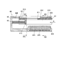
図10は、本実施形態におけるネイルプリント装置1の側断面図であり、図11は、図10に示す印刷指固定ユニットを指挿入方向Aから見た断面図である。
本実施形態において、印刷指固定ユニット70は、それぞれ1本の指を挿入可能に構成された4つの指挿入部材61と、この4つの指挿入部材61を支持する支持部材72とを備えている。指挿入部材61の構成は、第1の実施形態と同様であるため、同一部材には同一の符号を付してその説明を省略する。
FIG. 10 is a side sectional view of the nail printing apparatus 1 in the present embodiment, and FIG. 11 is a sectional view of the printing finger fixing unit shown in FIG.
In the present embodiment, the printing finger fixing unit 70 includes four finger insertion members 61 each configured to be able to insert one finger, and a support member 72 that supports the four finger insertion members 61. . Since the configuration of the finger insertion member 61 is the same as that of the first embodiment, the same members are denoted by the same reference numerals and description thereof is omitted.

図11に示すように、支持部材72の底部(図10、図11において下側)上には、指挿入部材61の各側壁の下端を受ける一対のガイド溝722が4つの指挿入部材61に対応する位置にそれぞれ指挿入方向Aに沿って形成されている。ガイド溝722は、指挿入部材61内に印刷指U1が挿入されて指挿入部材61が印刷指U1によって奥側に押し込まれた際に指挿入部材61を印刷指U1の指挿入方向Aに案内するガイド部である。   As shown in FIG. 11, a pair of guide grooves 722 that receive the lower ends of the side walls of the finger insertion member 61 are formed on the four finger insertion members 61 on the bottom portion (lower side in FIGS. 10 and 11) of the support member 72. A corresponding position is formed along the finger insertion direction A. The guide groove 722 guides the finger insertion member 61 in the finger insertion direction A of the printing finger U1 when the printing finger U1 is inserted into the finger insertion member 61 and the finger insertion member 61 is pushed backward by the printing finger U1. It is a guide part to do.

また、支持部材72の底部であって各指挿入部材61の各側壁を受けるガイド溝722の間にはそれぞれ凹部723が設けられている。この凹部723内には、指挿入部材61内に挿入される印刷指U1を下側から保持する指置き部材724と、この指置き部材724を下側から押し上げる押し上げ機構725とがそれぞれ設けられている。
指置き部材724及び押し上げ機構725の構成は、第1の実施形態と同様であるため、その説明を省略する。
In addition, a recess 723 is provided between the guide groove 722 that receives each side wall of each finger insertion member 61 at the bottom of the support member 72. In the recess 723, a finger placement member 724 for holding the printing finger U1 inserted into the finger insertion member 61 from the lower side and a push-up mechanism 725 for pushing up the finger placement member 724 from the lower side are provided. Yes.
Since the configuration of the finger placement member 724 and the push-up mechanism 725 is the same as that of the first embodiment, the description thereof is omitted.

また、本実施形態において、位置復帰用バネ63の一端は、突き当て部材613における印刷指U1が突き当てられる側とは反対の面に固定されており、位置復帰用バネ63の他端は、ケース本体2における指挿入方向Aの奥側の面に当接している。なお、位置復帰用バネ63の固定される位置等が限定されないことは第1の実施形態と同様である。   In the present embodiment, one end of the position return spring 63 is fixed to the surface of the abutting member 613 opposite to the side on which the printing finger U1 is abutted, and the other end of the position return spring 63 is The case main body 2 is in contact with the inner surface of the finger insertion direction A. It should be noted that the position where the position return spring 63 is fixed is not limited as in the first embodiment.

本実施形態では、指挿入部材71と撮影部30及び印刷部40との間に何ら介在するものがないため、撮影部30及び印刷部40は、指挿入部材61の爪部露出窓611に近接した位置に配置されている。   In this embodiment, since there is nothing interposed between the finger insertion member 71 and the imaging unit 30 and the printing unit 40, the imaging unit 30 and the printing unit 40 are close to the nail part exposure window 611 of the finger insertion member 61. It is arranged at the position.

なお、その他の構成は、第1の実施形態と同様であるため、その説明を省略する。   Since other configurations are the same as those of the first embodiment, the description thereof is omitted.

次に、本実施形態における作用について説明する。   Next, the operation in this embodiment will be described.

印刷指U1の爪部Tへの印刷を行う場合、ユーザは、爪部に印刷したいネイル画像パターンを選択し、印刷指固定部20の印刷指固定ユニット70内に印刷指U1を挿入する。
具体的には、例えば親指以外の4本の指(人差し指、中指、薬指及び小指)が印刷指U1となる場合には、ユーザは印刷指固定ユニット70の左端の指挿入部材61に小指、その右隣の指挿入部材61に薬指、さらにその右隣の指挿入部材61に中指、右端の指挿入部材61に人差し指を挿入するというように、4つの指挿入部材61にそれぞれ1本ずつ印刷指U1を挿入する。また、非印刷指挿入部20bに非印刷指である親指を挿入する。
When printing on the nail portion T of the printing finger U1, the user selects a nail image pattern to be printed on the nail portion, and inserts the printing finger U1 into the printing finger fixing unit 70 of the printing finger fixing portion 20.
Specifically, for example, when four fingers other than the thumb (index finger, middle finger, ring finger, and little finger) become the printing finger U1, the user places the little finger on the finger insertion member 61 on the left end of the printing finger fixing unit 70, One finger on each of the four finger insertion members 61, such as inserting a ring finger into the right finger insertion member 61, a middle finger into the right finger insertion member 61, and an index finger into the right finger insertion member 61. Insert U1. Further, a thumb that is a non-printing finger is inserted into the non-printing finger insertion portion 20b.

このように、親指以外の4本の指(人差し指、中指、薬指及び小指)をそれぞれ指挿入部材61に挿入する場合、各指挿入部材61は、印刷指U1の先端が突き当て部材613に突き当てられることによって指挿入方向Aの奥側に適宜スライド移動し、挿入されている各印刷指U1の長さに応じた位置で停止する。
各指挿入部材61のスライド移動が停止すると、制御部は押し上げ機構725を制御して、指置き部材724上に保持された印刷指U1を下側から押し上げ、印刷指U1の上面を指挿入部材61の上側の面の裏側(下側)に当接させる。これにより、各印刷指U1は、それぞれ指挿入部材61の爪部露出窓611から爪部Tが露出するとともに、爪部Tの生え際付近が指押え部612により上から押さえられて上側に上がらないように抑制された状態で固定される。
Thus, when four fingers other than the thumb (index finger, middle finger, ring finger, and little finger) are each inserted into the finger insertion member 61, each finger insertion member 61 has its tip of the printing finger U1 abutted against the abutting member 613. By being applied, it is appropriately slid to the back side in the finger insertion direction A, and stopped at a position corresponding to the length of each inserted printing finger U1.
When the sliding movement of each finger insertion member 61 stops, the control unit controls the push-up mechanism 725 to push up the printing finger U1 held on the finger placement member 724 from below, and the upper surface of the printing finger U1 is moved to the finger insertion member. It is made to contact | abut to the back side (lower side) of the upper surface of 61. FIG. As a result, each printing finger U1 is exposed from the nail portion exposure window 611 of the finger insertion member 61, and the vicinity of the hairline of the nail portion T is pressed from above by the finger press portion 612 and does not rise upward. It is fixed in a suppressed state.

印刷指U1が上記のように印刷指固定部20に固定されると、印刷指固定部20に固定された印刷指U1を撮影部30により撮影し、指爪画像を取得する。そして、取得された画像は表示部13に表示され、ユーザは表示部13に表示された画像を目視することにより、印刷指U1が正しい位置に挿入されているかを確認する。   When the printing finger U1 is fixed to the printing finger fixing unit 20 as described above, the printing finger U1 fixed to the printing finger fixing unit 20 is imaged by the imaging unit 30, and a fingernail image is acquired. The acquired image is displayed on the display unit 13, and the user visually checks the image displayed on the display unit 13 to confirm whether the printing finger U1 is inserted at the correct position.

印刷指U1が正しい位置に挿入されている場合には、印刷部40が作動され、指挿入部材61に挿入されている各印刷指U1の爪部Tに選択されたネイル画像パターン(デザイン)が印刷される。   When the printing finger U1 is inserted at the correct position, the printing unit 40 is activated, and the selected nail image pattern (design) is applied to the nail portion T of each printing finger U1 inserted into the finger insertion member 61. Printed.

印刷処理が完了すると、制御部は指押し上げ機構725を動作させて指置き部材724を元の位置まで戻す。そして、ユーザが指挿入部材から印刷指U1を引き抜くと、位置復帰用バネ63によって指挿入部材61がもとの位置まで押し戻される。   When the printing process is completed, the control unit operates the finger push-up mechanism 725 to return the finger placing member 724 to the original position. When the user pulls out the printing finger U1 from the finger insertion member, the finger insertion member 61 is pushed back to the original position by the position return spring 63.

以上のように、本実施形態によれば、爪部Tを露出させる爪部露出窓611と爪部Tの生え際近傍を上方から押さえる指押え部612と印刷指U1を挿入した際に印刷指U1の先端部が突き当たる突き当て部材613とを備え、印刷指U1を挿入した際に印刷指U1の長さに応じて指挿入方向Aに沿ってスライド移動する指挿入部材61に印刷指U1を挿入することにより印刷指U1の固定を行う。このため、どのような長さの指が印刷指U1として挿入された場合でも印刷指U1の長さに応じた位置まで指挿入部材61がスライド移動し、爪部露出窓611から爪部Tを露出させるとともに、指押え部612によって爪部Tの生え際近傍を上方から押さえることができ、できるだけ印刷ヘッド46に近い位置に印刷指U1の爪部Tを固定しつつ印刷指U1が上側に反ること等を防止することができる。これにより、指挿入部材61に印刷指U1を挿入するという簡易な手法により、近距離から正確にインクを着弾させて精緻な印刷を行うことができるとともに、印刷ヘッド46と印刷指U1との接触による印刷ヘッド46の破損、印刷指U1へのインク等の付着を確実に防ぐことができる。また、爪部Tの生え際近傍が指押え部612によって覆われた状態となることから、爪部Tの生え際近傍に印刷ヘッド46から飛散したインクが付着することを防止することができる。
また、印刷指固定ユニット70に設けられる支持部材72に、指挿入部材61内に印刷指U1が挿入された際に指挿入部材61を印刷指U1の指挿入方向Aに案内するガイド溝722を備えている。このため、印刷指U1が突き当て部材613に突き当たると、印刷指U1の先端で押し込むことにより指挿入部材61を円滑に指挿入方向Aの奥側にスライド移動させることができる。
また、指挿入部材61の下方には、樹脂等で形成された指置き部材724が配置されているため、指挿入部材61に挿入された印刷指U1を下方から安定的に保持することができ、印刷指U1を挿入するユーザの負担を軽減することができる。
また、指置き部材624を下方から押し上げる押し上げ機構625を備えているため、適度な高さまでユーザが自分で指置き部材624を押し上げる必要がなく、簡易に印刷指を適切な位置(すなわち、爪部Tと印刷ヘッド46との位置関係(距離等)において適切な位置)に固定することができる。
また、本実施形態では、印刷指固定部20に固定されている印刷指U1を撮影部30により撮影して指爪画像を取得し、この画像を表示部13に表示させるため、ユーザは表示部13の画面を確認するだけで、自分の指が適切な位置に配置されているか否かを簡易に確認することができる。
また、本実施形態では、第1の実施形態のように、指挿入部材61の上側を覆うカバー部材を設けていないため、指挿入部材61の爪部露出窓611から露出する爪部Tに極めて近接した位置に撮影部30及び印刷部40を配置することができる。このため、より鮮明な指爪画像を撮影することができる。また、印刷対象である爪部Tと印刷ヘッド46とを近づけることによりインクの吐出から着弾までの距離を短くすることができ、インク滴を正確に着弾させて一層精緻な印刷が可能になるとともに、インクミストの発生や、インクの周囲への飛散を抑えることが可能となる。
As described above, according to the present embodiment, the nail part exposure window 611 that exposes the nail part T, the finger presser part 612 that presses the vicinity of the hairline of the nail part T from above, and the printing finger U1 are inserted. And an abutting member 613 against which the leading end of the printing finger U1 comes into contact. When the printing finger U1 is inserted, the printing finger U1 is inserted into the finger insertion member 61 that slides along the finger insertion direction A according to the length of the printing finger U1. By doing so, the printing finger U1 is fixed. Therefore, regardless of the length of the finger inserted as the print finger U1, the finger insertion member 61 slides to a position corresponding to the length of the print finger U1, and the nail portion T is moved from the nail portion exposure window 611. In addition to being exposed, the vicinity of the edge of the nail portion T can be pressed from above by the finger pressing portion 612, and the printing finger U1 warps upward while fixing the nail portion T of the printing finger U1 as close to the print head 46 as possible. This can be prevented. Thus, by a simple method of inserting the printing finger U1 into the finger insertion member 61, ink can be landed accurately from a short distance and precise printing can be performed, and contact between the print head 46 and the printing finger U1 can be achieved. It is possible to reliably prevent damage to the print head 46 and adhesion of ink or the like to the print finger U1. Further, since the vicinity of the hairline of the nail portion T is covered with the finger pressing portion 612, it is possible to prevent ink scattered from the print head 46 from adhering to the vicinity of the hairline of the nail portion T.
In addition, a guide groove 722 that guides the finger insertion member 61 in the finger insertion direction A of the printing finger U1 when the printing finger U1 is inserted into the finger insertion member 61 is formed in the support member 72 provided in the printing finger fixing unit 70. I have. For this reason, when the printing finger U1 hits the abutting member 613, the finger insertion member 61 can be smoothly slid to the back side in the finger insertion direction A by being pushed in at the tip of the printing finger U1.
In addition, since a finger placement member 724 made of resin or the like is disposed below the finger insertion member 61, the printing finger U1 inserted into the finger insertion member 61 can be stably held from below. The burden on the user who inserts the printing finger U1 can be reduced.
In addition, since the push-up mechanism 625 that pushes up the finger placement member 624 from below is provided, it is not necessary for the user to push up the finger placement member 624 to an appropriate height, and the printing finger can be easily placed at an appropriate position (that is, the nail portion). It can be fixed at a suitable position in the positional relationship (distance etc.) between T and the print head 46.
In the present embodiment, the printing finger U1 fixed to the printing finger fixing unit 20 is imaged by the imaging unit 30 to acquire a fingernail image, and this image is displayed on the display unit 13. It is possible to easily check whether or not his / her finger is placed at an appropriate position by simply checking the 13 screens.
Further, in this embodiment, unlike the first embodiment, a cover member that covers the upper side of the finger insertion member 61 is not provided, so that the nail portion T exposed from the nail portion exposure window 611 of the finger insertion member 61 is extremely different. The photographing unit 30 and the printing unit 40 can be arranged at close positions. For this reason, a clearer fingernail image can be taken. In addition, the distance from ink ejection to landing can be shortened by bringing the nail portion T to be printed close to the print head 46, and ink droplets can be landed accurately to enable more precise printing. It is possible to suppress the occurrence of ink mist and the scattering of ink around the ink.

なお、本実施形態では、印刷指固定ユニット70が指挿入部材61と支持部材72とから構成され、支持部材72にガイド溝722、凹部723、指置き部材724、押し上げ機構725等が設けられている場合を例として説明したが、印刷指固定ユニット70の構成はこれに限定されず、支持部材72を備えない構成としてもよい。
この場合には、例えば、掴み部20cを構成する隔壁に指挿入部材61を案内するガイド溝や、凹部を形成し、この凹部内に指置き部材、押し上げ機構等を配置する構成とする。このように構成した場合には、印刷指固定ユニットを構成する部品点数を減少させることができ、装置の小型化、軽量化、低コスト化を図ることができる。
In this embodiment, the printing finger fixing unit 70 includes a finger insertion member 61 and a support member 72, and the support member 72 is provided with a guide groove 722, a recess 723, a finger placement member 724, a push-up mechanism 725, and the like. However, the configuration of the printing finger fixing unit 70 is not limited to this, and the support member 72 may not be provided.
In this case, for example, a guide groove or a concave portion for guiding the finger insertion member 61 is formed in the partition wall constituting the grip portion 20c, and a finger placement member, a push-up mechanism, and the like are arranged in the concave portion. When configured in this manner, the number of parts constituting the printing finger fixing unit can be reduced, and the apparatus can be reduced in size, weight, and cost.

[第3の実施の形態]
次に、図12から図14を参照しつつ、本発明に係るネイルプリント装置の第3の実施形態について説明する。なお、本実施形態は、印刷指固定ユニットの構成のみが第1の実施形態及び第2の実施形態と異なるものであるため、以下においては、特に第1の実施形態及び第2の実施形態と異なる点について説明する。
[Third Embodiment]
Next, a third embodiment of the nail print apparatus according to the present invention will be described with reference to FIGS. Note that this embodiment is different from the first embodiment and the second embodiment only in the configuration of the printing finger fixing unit. Therefore, in the following, in particular, the first embodiment and the second embodiment will be described. Different points will be described.

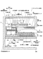
図12は、本実施形態における印刷指固定ユニットの側断面図であり、図13は、図12におけるXIII-XIII線に沿う断面図であり、図14は、図12におけるXIV-XIV線に沿う断面図である。
本実施形態において、印刷指固定ユニット80は、それぞれ1本の指を挿入可能に構成された4つの指挿入部材81と、この4つの指挿入部材81を収納するカバー部材82とを備えている。
12 is a side sectional view of the printing finger fixing unit in the present embodiment, FIG. 13 is a sectional view taken along line XIII-XIII in FIG. 12, and FIG. 14 is taken along line XIV-XIV in FIG. It is sectional drawing.
In the present embodiment, the printing finger fixing unit 80 includes four finger insertion members 81 each configured to be able to insert one finger, and a cover member 82 that accommodates the four finger insertion members 81. .

図12から図14に示すように、本実施形態において、指挿入部材81の両側壁の高さ寸法は、カバー部材82の高さの半分程度となっている。指挿入部材81には、第1の実施形態及び第2の実施形態と同様に、爪部露出窓811、指押え部812、突き当て部材813が設けられている。
また、指挿入部材81の上側(図12から図14において上側)には指挿入方向Aに沿って、断面ほぼT字状のガイドレール815が設けられている。
なお、その他の構成は、第1の実施形態及び第2の実施形態と同様であるため、その説明を省略する。
As shown in FIGS. 12 to 14, in this embodiment, the height dimension of both side walls of the finger insertion member 81 is about half of the height of the cover member 82. Similar to the first and second embodiments, the finger insertion member 81 is provided with a nail part exposure window 811, a finger presser part 812, and an abutting member 813.
A guide rail 815 having a substantially T-shaped cross section is provided along the finger insertion direction A on the upper side of the finger insertion member 81 (upper side in FIGS. 12 to 14).
Since other configurations are the same as those in the first embodiment and the second embodiment, description thereof is omitted.

カバー部材82の上側(図12から図14において上側)の内面であって、各指挿入部材81のガイドレール815に対応する位置には、ガイドレール815を受けるガイド溝826がそれぞれ設けられている。
また、カバー部材82の底部には幅方向のほぼ全体に亘って凹部823が設けられている。この凹部823内には、指挿入部材81内に挿入される印刷指U1を下側から保持する指置き部材824と、この指置き部材824を下側から押し上げる押し上げ機構825とが設けられている。
指置き部材824は、図13及び図14に示すように、4つの指挿入部材81の全てに亘るように、カバー部材82の幅方向のほぼ全体に延在して設けられている。これにより、4つの指挿入部材81に挿入される4本の印刷指U1全てを1つの指置き部材824によって保持することができる。なお、指置き部材824の構成はここに例示したものに限定されず、複数に分割された指置き部材を備えていてもよい。また、押し上げ機構825は、指置き部材824の幅とほぼ等しい押し上げ機構825を1つ備えてもよいし、指置き部材824の幅よりも小さい押し上げ機構825を複数配置してもよい。
Guide grooves 826 that receive the guide rails 815 are provided on the inner surface of the upper side (the upper side in FIGS. 12 to 14) of the cover member 82 and at positions corresponding to the guide rails 815 of each finger insertion member 81. .
Further, a recess 823 is provided on the bottom of the cover member 82 over substantially the entire width direction. In the recess 823, a finger placement member 824 that holds the printing finger U1 inserted into the finger insertion member 81 from the lower side and a push-up mechanism 825 that pushes up the finger placement member 824 from the lower side are provided. .
As shown in FIGS. 13 and 14, the finger placement member 824 is provided so as to extend over substantially the entire width direction of the cover member 82 so as to cover all of the four finger insertion members 81. Accordingly, all four printing fingers U1 inserted into the four finger insertion members 81 can be held by one finger placement member 824. In addition, the structure of the finger placement member 824 is not limited to what was illustrated here, You may provide the finger placement member divided | segmented into plurality. Further, the push-up mechanism 825 may include one push-up mechanism 825 that is substantially equal to the width of the finger placement member 824, or a plurality of push-up mechanisms 825 that are smaller than the width of the finger placement member 824 may be disposed.

なお、その他の構成は、第1の実施形態及び第2の実施形態と同様であるため、その説明を省略する。   Since other configurations are the same as those in the first embodiment and the second embodiment, description thereof is omitted.

次に、本実施形態における作用について説明する。   Next, the operation in this embodiment will be described.

印刷指U1の爪部Tへの印刷を行う場合、ユーザは、爪部Tに印刷したいネイル画像パターンを選択し、印刷指固定部20の印刷指固定ユニット80内に印刷指U1を挿入する。
具体的には、例えば親指以外の4本の指(人差し指、中指、薬指及び小指)が印刷指U1となる場合には、ユーザは印刷指固定ユニット80の左端の指挿入部材81に小指、その右隣の指挿入部材81に薬指、さらにその右隣の指挿入部材81に中指、右端の指挿入部材81に人差し指を挿入するというように、4つの指挿入部材81にそれぞれ1本ずつ印刷指U1を挿入する。また、非印刷指挿入部に非印刷指である親指を挿入する。
When printing on the nail portion T of the printing finger U1, the user selects a nail image pattern to be printed on the nail portion T, and inserts the printing finger U1 into the printing finger fixing unit 80 of the printing finger fixing portion 20.
Specifically, for example, when four fingers other than the thumb (index finger, middle finger, ring finger, and little finger) become the printing finger U1, the user places the little finger on the finger insertion member 81 at the left end of the printing finger fixing unit 80, One finger is printed on each of the four finger insertion members 81, such as inserting a ring finger into the right finger insertion member 81, a middle finger into the right finger insertion member 81, and an index finger into the right finger insertion member 81. Insert U1. Further, a thumb that is a non-printing finger is inserted into the non-printing finger insertion portion.

このように、親指以外の4本の指(人差し指、中指、薬指及び小指)をそれぞれ指挿入部材81に挿入する場合、各指挿入部材81は、印刷指U1の先端が突き当て部材813に突き当てられることによって指挿入方向Aの奥側に適宜スライド移動し、挿入されている各印刷指U1の長さに応じた位置で停止する。
各指挿入部材81のスライド移動が停止すると、制御部は押し上げ機構825を制御して、指置き部材824上に保持された印刷指U1を下側から押し上げ、印刷指U1の上面を指挿入部材81の上側の面の裏側(下側)に当接させる。これにより、各印刷指U1は、それぞれ指挿入部材81の爪部露出窓611から爪部Tが露出するとともに、爪部Tの生え際付近が指押え部812により上から押さえられて上側に上がらないように抑制された状態で固定される。
Thus, when four fingers other than the thumb (index finger, middle finger, ring finger, and little finger) are each inserted into the finger insertion member 81, each finger insertion member 81 has its front end of the printing finger U1 abutted against the abutting member 813. By being applied, it is appropriately slid to the back side in the finger insertion direction A, and stopped at a position corresponding to the length of each inserted printing finger U1.
When the sliding movement of each finger insertion member 81 stops, the control unit controls the push-up mechanism 825 to push up the printing finger U1 held on the finger placement member 824 from below, and the upper surface of the printing finger U1 is moved to the finger insertion member. It is made to contact | abut to the back side (lower side) of the upper surface of 81. FIG. As a result, each printing finger U1 is exposed from the nail portion exposure window 611 of the finger insertion member 81, and the vicinity of the hairline of the nail portion T is pressed from above by the finger press portion 812 and does not rise upward. It is fixed in a suppressed state.

印刷指U1が上記のように印刷指固定部に固定されると、印刷指固定部に固定された印刷指U1を撮影部により撮影し、指爪画像を取得する。そして、取得された画像は表示部に表示され、ユーザは表示部に表示された画像を目視することにより、印刷指U1が正しい位置に挿入されているかを確認する。   When the printing finger U1 is fixed to the printing finger fixing unit as described above, the printing finger U1 fixed to the printing finger fixing unit is photographed by the photographing unit, and a fingernail image is acquired. The acquired image is displayed on the display unit, and the user visually checks the image displayed on the display unit to confirm whether the printing finger U1 is inserted at the correct position.

印刷指U1が正しい位置に挿入されている場合には、印刷部が作動され、指挿入部材81に挿入されている各印刷指U1の爪部Tに選択されたネイル画像パターン(デザイン)が印刷される。   When the printing finger U1 is inserted at the correct position, the printing unit is activated, and the selected nail image pattern (design) is printed on the nail portion T of each printing finger U1 inserted in the finger insertion member 81. Is done.

印刷処理が完了すると、制御部は指押し上げ機構825を動作させて指置き部材824を元の位置まで戻す。そして、ユーザが指挿入部材81から印刷指U1を引き抜くと、位置復帰用バネ83によって指挿入部材81がもとの位置まで押し戻される。   When the printing process is completed, the control unit operates the finger push-up mechanism 825 to return the finger placing member 824 to the original position. When the user pulls out the printing finger U1 from the finger insertion member 81, the finger insertion member 81 is pushed back to the original position by the position return spring 83.

以上のように、本実施形態によれば、爪部Tを露出させる爪部露出窓811と爪部Tの生え際近傍を上方から押さえる指押え部812と印刷指U1を挿入した際に印刷指U1の先端部が突き当たる突き当て部材813とを備え、印刷指U1を挿入した際に印刷指U1の長さに応じて指挿入方向Aに沿ってスライド移動する指挿入部材81に印刷指U1を挿入することにより印刷指U1の固定を行う。このため、どのような長さの指が印刷指U1として挿入された場合でも印刷指U1の長さに応じた位置まで指挿入部材81がスライド移動し、爪部露出窓811から爪部Tを露出させるとともに、指押え部812によって爪部Tの生え際近傍を上方から押さえることができ、できるだけ印刷ヘッドに近い位置に印刷指U1の爪部Tを固定しつつ印刷指U1が上側に反ること等を防止することができる。これにより、指挿入部材81に印刷指U1を挿入するという簡易な手法により、近距離から正確にインクを着弾させて精緻な印刷を行うことができるとともに、印刷ヘッドと印刷指U1との接触による印刷ヘッドの破損、印刷指U1へのインク等の付着を確実に防ぐことができる。また、爪部Tの生え際近傍が指押え部812によって覆われた状態となることから、爪部Tの生え際近傍に印刷ヘッドから飛散したインクが付着することを防止することができる。
また、指挿入部材81の上側にガイドレール815を設け、カバー部材82の上面にこのガイドレール815を受けて指挿入部材81を指挿入方向Aに案内するガイド溝826を備えている。このため、印刷指U1が突き当て部材813に突き当たると、印刷指U1の先端で押し込むことにより指挿入部材81を円滑に指挿入方向Aの奥側にスライド移動させることができる。
また、このようにガイド部としてのガイドレール815及びガイド溝826を指挿入部材81の上側に設けることにより、カバー部材82の底面に設けられる指置き部材824及び押し上げ機構825を4つの指挿入部材81全てに対応する1つながりのものとすることができる。このため、部品点数の減少による製造工程の簡易化及びコストの低減を実現することができる。
As described above, according to the present embodiment, the nail part exposure window 811 that exposes the nail part T, the finger press part 812 that presses the vicinity of the hairline of the nail part T from above, and the printing finger U1 are inserted. The printing finger U1 is inserted into a finger insertion member 81 that slides along the finger insertion direction A according to the length of the printing finger U1 when the printing finger U1 is inserted. By doing so, the printing finger U1 is fixed. Therefore, regardless of the length of the finger inserted as the printing finger U1, the finger insertion member 81 slides to a position corresponding to the length of the printing finger U1, and the nail portion T is moved from the nail portion exposure window 811. In addition to being exposed, the vicinity of the edge of the nail portion T can be pressed from above by the finger pressing portion 812, and the printing finger U1 warps upward while fixing the nail portion T of the printing finger U1 as close to the print head as possible. Etc. can be prevented. Thereby, by a simple method of inserting the printing finger U1 into the finger insertion member 81, ink can be landed accurately from a short distance and precise printing can be performed, and by the contact between the print head and the printing finger U1. It is possible to reliably prevent damage to the print head and adhesion of ink or the like to the print finger U1. Further, since the vicinity of the hairline of the nail portion T is covered with the finger pressing portion 812, it is possible to prevent ink scattered from the print head from adhering to the vicinity of the hairline of the nail portion T.
Further, a guide rail 815 is provided on the upper side of the finger insertion member 81, and a guide groove 826 for receiving the guide rail 815 and guiding the finger insertion member 81 in the finger insertion direction A is provided on the upper surface of the cover member 82. For this reason, when the printing finger U1 hits the abutting member 813, the finger insertion member 81 can be smoothly slid to the back side in the finger insertion direction A by being pushed in at the tip of the printing finger U1.
Further, by providing the guide rail 815 and the guide groove 826 as the guide portion on the upper side of the finger insertion member 81 in this manner, the finger placement member 824 and the push-up mechanism 825 provided on the bottom surface of the cover member 82 are replaced with four finger insertion members. One connection corresponding to all 81 can be used. For this reason, simplification of the manufacturing process and reduction of cost can be realized by reducing the number of parts.

なお、本実施形態では、印刷指固定ユニット80が指挿入部材81とカバー部材82とから構成され、カバー部材82にガイド溝822、凹部823、指置き部材824、押し上げ機構825等が設けられている場合を例として説明したが、印刷指固定ユニット80の構成はこれに限定されない。
例えば、カバー部材82を底面のない構成として指挿入部材81のガイドレール815を受けるガイド溝826のみを設けるとともに、掴み部20cを構成する隔壁に凹部を形成し、この凹部内に指置き部材、押し上げ機構等を配置する構成としてもよい。このように構成した場合には、カバー部材82を底面の厚み分だけ印刷指固定ユニット80の厚みを薄くすることができ、装置の小型化、軽量化を図ることができる。
In the present embodiment, the printing finger fixing unit 80 includes a finger insertion member 81 and a cover member 82, and the cover member 82 is provided with a guide groove 822, a recess 823, a finger placing member 824, a push-up mechanism 825, and the like. However, the configuration of the printing finger fixing unit 80 is not limited to this.
For example, the cover member 82 is configured without a bottom surface, and only the guide groove 826 that receives the guide rail 815 of the finger insertion member 81 is provided, and a recess is formed in the partition wall that forms the grip portion 20c, and the finger placement member, It is good also as a structure which arranges a pushing-up mechanism etc. When configured in this manner, the thickness of the printing finger fixing unit 80 can be reduced by the thickness of the bottom surface of the cover member 82, and the apparatus can be reduced in size and weight.

[第4の実施の形態]
次に、図15から図21を参照しつつ、本発明に係るネイルプリント装置の第4の実施形態について説明する。なお、本実施形態は、印刷指固定ユニットの構成のみが第1の実施形態と異なるものであるため、以下においては、特に第1の実施形態と異なる点について説明する。
[Fourth Embodiment]
Next, a fourth embodiment of the nail print apparatus according to the present invention will be described with reference to FIGS. Note that this embodiment is different from the first embodiment only in the configuration of the printing finger fixing unit, and therefore, the following description will focus on differences from the first embodiment.

図15は、本実施形態におけるネイルプリント装置1の側断面図である。
図15に示すように、本実施形態において、ネイルプリント装置1の指固定ユニット収容部20aには、第1の実施形態と同様に、印刷指U1を固定する印刷指固定ユニット60が収容されている。
FIG. 15 is a side sectional view of the nail print apparatus 1 in the present embodiment.
As shown in FIG. 15, in the present embodiment, the finger fixing unit housing portion 20a of the nail printing apparatus 1 houses the printing finger fixing unit 60 that fixes the printing finger U1 as in the first embodiment. Yes.

本実施形態において、印刷指固定ユニット60は、印刷指U1を挿入可能な指挿入部材61と、この指挿入部材61を収納するカバー部材62とを備えている。
なお、本実施形態では、第1の実施形態と同様に、複数の印刷指に対応して複数の指挿入部材61(図示例では4つの指挿入部材61)を備えている場合を例として説明するが、印刷指固定ユニット60に備えられる指挿入部材61は4つに限定されない。例えば印刷指U1を1本ずつ印刷するネイルプリント装置1であれば、指挿入部材61が1つ設けられていればよい。また、印刷しようとする指の種類や数等に応じて印刷指固定ユニット60に収容される指挿入部材61を入れ替えて、その種類や数を変更できるようにしてもよい。
In the present embodiment, the printing finger fixing unit 60 includes a finger insertion member 61 into which the printing finger U1 can be inserted, and a cover member 62 that houses the finger insertion member 61.
In the present embodiment, as in the first embodiment, a case where a plurality of finger insertion members 61 (four finger insertion members 61 in the illustrated example) are provided corresponding to a plurality of printing fingers will be described as an example. However, the number of finger insertion members 61 provided in the printing finger fixing unit 60 is not limited to four. For example, in the case of the nail printing apparatus 1 that prints the printing fingers U1 one by one, one finger insertion member 61 may be provided. Further, the finger insertion member 61 accommodated in the printing finger fixing unit 60 may be exchanged according to the type and number of fingers to be printed, so that the type and number can be changed.

各指挿入部材61の内側であって爪部露出窓611よりも指挿入方向A(図15等参照)の奥側には、指挿入部材61に印刷指U1が挿入された際に印刷指U1の先端部が突き当たる突き当て部材650が設けられている。突き当て部材650は、第1の実施形態と同様に、爪部露出窓611における指挿入方向Aの奥側の端縁から下方(すなわち、指挿入部材61の開口側)に向かってほぼ垂直に立設されている板状の部材である。   When the printing finger U1 is inserted into the finger insertion member 61 inside the finger insertion member 61 and behind the nail portion exposure window 611 in the finger insertion direction A (see FIG. 15 and the like), the printing finger U1 The abutting member 650 with which the front-end | tip part abuts is provided. Similar to the first embodiment, the abutting member 650 is substantially perpendicular to the lower edge (that is, the opening side of the finger insertion member 61) from the edge on the back side in the finger insertion direction A of the nail portion exposure window 611. It is the plate-shaped member erected.

本実施形態において、各突き当て部材650における印刷指U1の先端部が突き当たる側には、凹部651が形成されている。各突き当て部材650の凹部651には、それぞれ一端が凹部651内に固定され、自由端が凹部651から浮き上がるように取り付けられた板スイッチ部652が設けられている。板スイッチ部652は、バネ性を有する板状の部材であり、凹部651から浮き上がっている自由端側がある程度強い押圧力によって押し込まれ凹部651内に押し付けられると、ON状態となってON信号を出力し、自由端側が凹部651から離れるとOFF状態となってOFF信号を出力するようになっている。板スイッチ部652から出力された信号は、後述する制御部50に送られる。   In the present embodiment, a concave portion 651 is formed on the side of each abutting member 650 where the leading end of the printing finger U1 abuts. The recess 651 of each abutting member 650 is provided with a plate switch portion 652 that is fixed so that one end is fixed in the recess 651 and the free end is lifted from the recess 651. The plate switch portion 652 is a plate-like member having a spring property, and when the free end floating from the concave portion 651 is pushed into the concave portion 651 with a certain amount of strong pressing force, it is turned on and outputs an ON signal. When the free end side moves away from the recess 651, the OFF state is entered and an OFF signal is output. The signal output from the plate switch unit 652 is sent to the control unit 50 described later.

本実施形態では、印刷指U1が指挿入部材61内に挿入され、印刷指U1の先端部が板スイッチ部652の自由端側を押し込むと、自由端側の浮き上がっている部分が凹部651の内側に接触し、ON状態となってON信号を出力する。また、印刷指U1が指挿入部材61内から引き抜かれる等により印刷指U1の先端部が板スイッチ部652から離間して板スイッチ部652の自由端側が凹部651から浮き上がると、OFF状態となってOFF信号を出力する。
このように、板スイッチ部652は、印刷指U1の突き当て部材650に対する接離を検出する接離検出手段として機能する。
なお、接離検出手段としての板スイッチ部652は、指挿入部材61が複数設けられている場合には、各指挿入部材61における突き当て部材650にそれぞれ設けられる。
板スイッチ部652は、その自由端側が凹部651内に押し付けられた状態において、突き当て部材650における印刷指U1の先端部が突き当たる側の面とほぼ面一となるようになっている。
なお、板スイッチ部652の設けられる位置や範囲、形状、大きさ等は図示例に限定されず、指挿入部材61に挿入された印刷指U1の突き当て部材650に対する接離を検出することができるように配置されていればよい。
In the present embodiment, when the printing finger U1 is inserted into the finger insertion member 61 and the front end portion of the printing finger U1 pushes in the free end side of the plate switch portion 652, the floating portion on the free end side is inside the recess 651. Is turned ON and an ON signal is output. Further, when the printing finger U1 is pulled out of the finger insertion member 61 and the tip of the printing finger U1 is separated from the plate switch portion 652 and the free end side of the plate switch portion 652 is lifted from the recess 651, the OFF state is established. Outputs an OFF signal.
Thus, the board switch unit 652 functions as a contact / separation detection unit that detects contact / separation of the printing finger U1 with respect to the abutting member 650.
When a plurality of finger insertion members 61 are provided, the plate switch portion 652 serving as the contact / separation detection means is provided on the abutting member 650 in each finger insertion member 61.
The plate switch portion 652 is substantially flush with the surface of the abutting member 650 on which the leading end of the printing finger U1 abuts in a state where the free end side is pressed into the recess 651.
The position, range, shape, size, and the like of the plate switch unit 652 are not limited to the illustrated example, and the contact / separation of the printing finger U1 inserted into the finger insertion member 61 with respect to the abutting member 650 can be detected. It only has to be arranged so that it can.

また、指挿入部材61の突き当て部材650の下端部には、指挿入部材61が指挿入方向Aに沿ってスライド移動した際に、これと反対の方向に指挿入部材61が移動することを規制する逆移動規制部材としてのストッパ機構653が設けられている。   In addition, when the finger insertion member 61 slides along the finger insertion direction A, the finger insertion member 61 moves in the opposite direction to the lower end of the abutting member 650 of the finger insertion member 61. A stopper mechanism 653 is provided as a reverse movement restricting member for restricting.

図16(A)及び図16(B)は、本実施形態における突き当て部材650及びストッパ機構653を示す側断面図であり、図17(A)は、ストッパ機構653を拡大して指挿入方向A(図15参照)から見た正面図であり、図17(B)は、図17(A)のB-B線に沿う側断面図であり、図17(C)は、図17(B)のストッパ部材655が回動した状態を示す側断面図である。
図16(A)、(B)及び図17(A)から(C)に示すように、ストッパ機構653は、突き当て部材650の下端部に固定されたストッパ支持部材654と、このストッパ支持部材654に対して回転軸656により軸支されたストッパ部材655とを備えている。
16A and 16B are side sectional views showing the abutting member 650 and the stopper mechanism 653 in this embodiment, and FIG. 17A is an enlarged view of the stopper mechanism 653 and the finger insertion direction. It is the front view seen from A (refer FIG. 15), FIG.17 (B) is a sectional side view along the BB line of FIG.17 (A), FIG.17 (C) is FIG.17 (B). It is a sectional side view which shows the state which the stopper member 655 of FIG.
As shown in FIGS. 16A and 16B and FIGS. 17A to 17C, the stopper mechanism 653 includes a stopper support member 654 fixed to the lower end portion of the abutting member 650, and the stopper support member. And a stopper member 655 that is pivotally supported by a rotating shaft 656 with respect to 654.

ストッパ支持部材654における指挿入方向Aの奥側(図15において左側)には、ストッパ部材655が図16(B)における矢印方向とは逆の方向に回動することを防止する反転規制部657が設けられている。
ストッパ部材655は、回転軸656を支点として、図16(B)の矢印方向に回動可能となっており、所定量以上回動した際は、その回動状態を維持し得るようになっている。すなわち、ストッパ部材655の上端部の少なくとも一部は、例えば凹凸等が施された滑り止め加工部658となっており、この滑り止め加工部658がストッパ支持部材654の内側面と接触すると、摩擦力によりストッパ部材655の自由な回動が規制され、回動状態が維持される。なお、ストッパ部材655が回動状態を維持し得る構成は図示例に限定されない。例えば、ストッパ部材655の上端部とストッパ支持部材654の内側面とにそれぞれ互いに係止し合う凸部と凹部とを設けて、ストッパ部材655が所定量以上回動した際には、この凸部と凹部とが互いに係止されてストッパ部材655の自由な回動を規制する等、各種他の構成を適用してもよい。また、回転軸656に滑りにくい加工を施す等により、一旦大きく押し上げられた際には回動状態が維持されるようにしてもよい。
On the far side (left side in FIG. 15) of the finger insertion direction A in the stopper support member 654, the reverse regulating portion 657 for preventing the stopper member 655 from rotating in the direction opposite to the arrow direction in FIG. Is provided.
The stopper member 655 can be rotated in the direction of the arrow in FIG. 16B with the rotation shaft 656 as a fulcrum. When the stopper member 655 rotates more than a predetermined amount, the rotation state can be maintained. Yes. That is, at least a part of the upper end portion of the stopper member 655 is, for example, a non-slip processing portion 658 having unevenness, and when the anti-slip processing portion 658 comes into contact with the inner side surface of the stopper support member 654, friction is caused. The free rotation of the stopper member 655 is restricted by the force, and the rotation state is maintained. The configuration in which the stopper member 655 can maintain the rotating state is not limited to the illustrated example. For example, when the upper end of the stopper member 655 and the inner surface of the stopper support member 654 are provided with a convex portion and a concave portion that are engaged with each other, and the stopper member 655 rotates more than a predetermined amount, this convex portion Various other configurations may be applied, such as locking the recess and the recess to restrict the free rotation of the stopper member 655. Alternatively, the rotating shaft 656 may be processed so as not to slip, so that the rotating state may be maintained once it is largely pushed up.

ストッパ部材655は、例えば、指挿入部材61の突き当て部材650の幅方向(すなわち指挿入部材61に挿入される印刷指U1の指幅方向)に延在する板状の部材であり、ストッパ部材655の下端部は、指挿入部材61を収納するカバー部材62の底面に接触している。本実施形態では、図16(A)及び図16(B)に示すように、カバー部材62の底面に凹凸部661が設けられており、ストッパ部材655は、その下端部とカバー部材62側の凹凸部661との摩擦力により指挿入部材61が移動することを規制する。
なお、ストッパ部材655は、指挿入部材61の移動を規制することができるものであればよく、その形状等は特に限定されない。例えば、ストッパ部材655は、板状の部材ではなく、棒状の部材であってもよい。
The stopper member 655 is, for example, a plate-like member extending in the width direction of the abutting member 650 of the finger insertion member 61 (that is, the finger width direction of the printing finger U1 inserted into the finger insertion member 61). The lower end portion of 655 is in contact with the bottom surface of the cover member 62 that houses the finger insertion member 61. In the present embodiment, as shown in FIGS. 16A and 16B, an uneven portion 661 is provided on the bottom surface of the cover member 62, and the stopper member 655 has a lower end portion and a cover member 62 side. The movement of the finger insertion member 61 is restricted by the frictional force with the uneven portion 661.
The stopper member 655 is not particularly limited as long as it can regulate the movement of the finger insertion member 61. For example, the stopper member 655 may be a rod-like member instead of a plate-like member.

本実施形態では、前述のように、ストッパ部材655は、反転規制部657により図16(B)における矢印方向とは逆の方向に回動しないように規制されており、他方で、図16(B)における矢印方向には、所定量までは自由に回動するようになっている。
このため、印刷指U1が指挿入部材61に挿入されて、突き当て部材650が印刷指U1の先端部により指挿入方向Aに押し込まれた際には、ストッパ部材655は、図16(B)における矢印方向に僅かに回動しながら凹凸部661を乗り越えていくため、ストッパ部材655の下端部とカバー部材62側の凹凸部661との間で大きな摩擦力を生じることなく、指挿入部材61を円滑にスライド移動させることができる。他方、突き当て部材650は、位置復帰用バネ63によって指挿入方向Aの奥側から手前側に向かって押圧されている。このため、印刷指U1が突き当て部材650の板スイッチ部652から離れる方向に動いた際には、指挿入方向A(図16及び図17における矢印A)とは反対の方向に押し込まれる。この場合、ストッパ部材655は、図16(B)における矢印方向とは逆の方向に回動しないため、凹凸部661との間で大きな摩擦力を生じ、これにより、指挿入部材61は、指挿入方向Aと反対の方向に移動することを規制され、印刷指U1の動きに追従することなく、その場で停止するか、位置復帰用バネ63によってごくゆっくりと押し戻される。
In the present embodiment, as described above, the stopper member 655 is regulated by the reverse regulating portion 657 so as not to rotate in the direction opposite to the arrow direction in FIG. In the direction of the arrow in B), it can freely rotate up to a predetermined amount.
For this reason, when the printing finger U1 is inserted into the finger insertion member 61 and the abutting member 650 is pushed in the finger insertion direction A by the tip of the printing finger U1, the stopper member 655 is moved as shown in FIG. The finger insertion member 61 does not generate a large frictional force between the lower end portion of the stopper member 655 and the concavo-convex portion 661 on the cover member 62 side while slightly rotating in the direction of the arrow in FIG. Can be slid smoothly. On the other hand, the abutting member 650 is pressed from the back side in the finger insertion direction A toward the front side by the position return spring 63. For this reason, when the printing finger U1 moves in a direction away from the plate switch portion 652 of the abutting member 650, the printing finger U1 is pushed in the direction opposite to the finger insertion direction A (arrow A in FIGS. 16 and 17). In this case, since the stopper member 655 does not rotate in the direction opposite to the arrow direction in FIG. 16B, a large frictional force is generated between the stopper member 655 and the uneven portion 661. It is restricted from moving in the direction opposite to the insertion direction A and stops on the spot without following the movement of the printing finger U1, or is pushed back very slowly by the position return spring 63.

また、図16(A)及び図16(B)に示すように、カバー部材62の底面であって、凹凸部661が設けられている位置よりも指挿入方向Aの奥側には、ストッパ部材655を解除する規制解除部材662が設けられている。規制解除部材662は、断面ほぼL字状の部材であり、ストッパ部材655の下端部を図16(B)における矢印方向に押し上げて、ストッパ部材655を矢印方向に所定量以上回動させる。これにより、前述のように、滑り止め加工部658がストッパ支持部材654の内側面と接触して、その摩擦力によりストッパ部材655の自由な回動が規制され、ストッパ部材655は回動状態を維持される。その結果、ストッパ部材655と凹凸部661との間に摩擦力を生じなくなるため、指挿入部材61は、位置復帰用バネ63の押圧力によって指挿入方向Aと反対の方向に円滑に移動し、印刷指U1を挿入する前の初期位置まで復帰する。
なお、規制解除部材662の形状や配置する位置等は図示例に限定されない。
Further, as shown in FIGS. 16A and 16B, a stopper member is provided on the bottom surface of the cover member 62 on the back side in the finger insertion direction A from the position where the uneven portion 661 is provided. A restriction releasing member 662 for releasing 655 is provided. The restriction release member 662 is a member having an approximately L-shaped cross section, and pushes up the lower end portion of the stopper member 655 in the arrow direction in FIG. 16B to rotate the stopper member 655 in the arrow direction by a predetermined amount or more. As a result, as described above, the anti-slip processing portion 658 comes into contact with the inner surface of the stopper support member 654, and the free rotation of the stopper member 655 is restricted by the frictional force. Maintained. As a result, since no frictional force is generated between the stopper member 655 and the concavo-convex portion 661, the finger insertion member 61 smoothly moves in the direction opposite to the finger insertion direction A by the pressing force of the position return spring 63, It returns to the initial position before inserting the printing finger U1.
In addition, the shape of the restriction release member 662, the position where it is arranged, and the like are not limited to the illustrated example.

本実施形態では、印刷指U1が一旦突き当て部材650の板スイッチ部652から離れて指挿入部材61の挿入が停止した後に、再度印刷指U1によってさらに指挿入方向Aの奥側に突き当て部材650が押し込まれると、ストッパ部材655の下端部が規制解除部材662に突き当てられて図16(B)における矢印方向に押し上げられ、ストッパ部材655による指挿入部材61の移動規制が解除されるようになっている。   In this embodiment, after the printing finger U1 is once separated from the plate switch portion 652 of the abutting member 650 and the insertion of the finger insertion member 61 is stopped, the abutting member is further moved further back in the finger insertion direction A by the printing finger U1. When 650 is pushed, the lower end portion of the stopper member 655 is abutted against the restriction release member 662 and pushed up in the direction of the arrow in FIG. 16B, so that the movement restriction of the finger insertion member 61 by the stopper member 655 is released. It has become.

図18は、本実施形態における制御構成を示す要部ブロック図である。
本実施形態において、制御部50には、接離検出手段である板スイッチ部652からON信号又はOFF信号が送られるようになっている。
すなわち、前述のように、板スイッチ部652は、指挿入部材61に挿入された印刷指U1の先端部によって押し込まれ、突き当て部材650(本実施形態では突き当て部材650の凹部651)に突き当てられると、板スイッチ部652がON状態となり、印刷指U1が突き当て部材650に接している旨の検出信号(すなわち、ON信号)を制御部50に出力する。また、板スイッチ部652は、一旦印刷指U1が突き当て部材650に接している旨を検出した後に板スイッチ部652が突き当て部材650(本実施形態では突き当て部材650の凹部651)から離れると、板スイッチ部652がOFF状態となり、印刷指U1が突き当て部材650から離間した旨の検出信号(すなわち、OFF信号)を制御部50に出力する。
FIG. 18 is a principal block diagram showing a control configuration in the present embodiment.
In the present embodiment, an ON signal or an OFF signal is sent to the control unit 50 from a plate switch unit 652 that is a contact / separation detection unit.
That is, as described above, the plate switch portion 652 is pushed by the tip of the printing finger U1 inserted into the finger insertion member 61, and hits the abutting member 650 (in this embodiment, the concave portion 651 of the abutting member 650). When applied, the plate switch unit 652 is turned on, and a detection signal (that is, an ON signal) indicating that the printing finger U1 is in contact with the abutting member 650 is output to the control unit 50. Further, the plate switch portion 652 once detects that the printing finger U1 is in contact with the abutting member 650, and then the plate switch portion 652 is separated from the abutting member 650 (in this embodiment, the concave portion 651 of the abutting member 650). Then, the plate switch unit 652 is turned off, and a detection signal (that is, an OFF signal) indicating that the printing finger U1 is separated from the abutting member 650 is output to the control unit 50.

制御部50は、板スイッチ部652により印刷指U1が突き当て部材650に接していると検出された場合、すなわち、板スイッチ部652からON信号が出力された場合には、当該接触検出時(ON信号受信時)又はこの接触検出時から所定の時間経過後に爪部Tへの印刷動作を開始するように、印刷手段である印刷部40を制御する。具体的には、第1モータ43、第2モータ47を駆動させて印刷ヘッド46を適宜移動させながら、印刷用データに基づいて印刷ヘッド43を駆動させ、爪部T上にインクを吐出させて、爪部Tへの印刷を行わせる。
なお、印刷指U1が突き当て部材650に接していると検出した検出時(ON信号受信時)からどのタイミングで印刷を開始させるかは、例えば10秒経過後等、デフォルトで設定されていてもよいし、ユーザが自由に設定できるようになっていてもよい。
When the plate switch unit 652 detects that the printing finger U1 is in contact with the abutting member 650, that is, when the ON signal is output from the plate switch unit 652, the control unit 50 detects the contact ( When the ON signal is received) or after a predetermined time elapses from the detection of the contact, the printing unit 40 that is a printing unit is controlled to start the printing operation on the nail T. Specifically, while driving the first motor 43 and the second motor 47 to appropriately move the print head 46, the print head 43 is driven based on the printing data to eject ink onto the nail portion T. Then, printing on the nail portion T is performed.
Note that the timing at which printing is started from the time of detection that the printing finger U1 is in contact with the abutting member 650 (when the ON signal is received) may be set by default, for example, after 10 seconds. The user may be able to set freely.

また、印刷動作開始後に、板スイッチ部652により印刷指U1の突き当て部材650からの離間が検出された場合、すなわち、板スイッチ部652からOFF信号が出力された場合には、爪部Tへの印刷動作を停止させるように、印刷部40を制御する。具体的には、第1モータ43、第2モータ47を停止させて印刷ヘッド46を停止させるとともに、印刷ヘッド43の駆動を停止させて、爪部T上へのインク吐出を停止させ、爪部Tへの印刷を中止させる。また、印刷動作が中止された場合には、制御部50は、表示部13を制御して、その旨を表示部13に表示させるようになっている。
このように、本実施形態において、制御部50は、接離検出手段である板スイッチ部652による検出結果に応じて印刷手段である印刷部40を制御する印刷制御手段として機能する。
Further, after the printing operation is started, when the separation of the printing finger U1 from the abutting member 650 is detected by the plate switch unit 652, that is, when the OFF signal is output from the plate switch unit 652, the nail portion T is output. The printing unit 40 is controlled to stop the printing operation. Specifically, the first motor 43 and the second motor 47 are stopped to stop the print head 46, and the drive of the print head 43 is stopped to stop ink ejection on the nail portion T. Stop printing on T. Further, when the printing operation is stopped, the control unit 50 controls the display unit 13 to display the fact on the display unit 13.
As described above, in the present embodiment, the control unit 50 functions as a print control unit that controls the printing unit 40 that is a printing unit in accordance with a detection result by the plate switch unit 652 that is a contact / separation detection unit.

なお、本実施形態では、片手の1本の指(例えば右手の親指等)が印刷指U1となる場合にも、片手の複数の指(例えば右手の人指し指、中指、薬指、小指の4指等)や両手の指(例えば両手の親指等)等、複数の指が印刷指U1となる場合にも、対応可能となっている。
複数の指が印刷指U1である場合には、印刷指U1が挿入された全ての指挿入部材61に設けられている板スイッチ部652により印刷指U1が突き当て部材650に接していると検出された場合(すなわち、全ての板スイッチ部652からON信号が出力された場合)に、制御部50は、当該接触検出時(ON信号受信時)又はこの接触検出時から所定の時間経過後に爪部Tへの印刷動作を開始するように、印刷手段である印刷部40を制御する。
また、印刷動作開始後に、複数の板スイッチ部652のうちの少なくとも1つにより印刷指U1の突き当て部材650からの離間が検出された場合(すなわち、いずれかの板スイッチ部652からOFF信号が出力された場合)に、制御部50は、爪部Tへの印刷動作を停止させるように、印刷部40を制御する。
In the present embodiment, even when one finger of one hand (for example, the thumb of the right hand) becomes the printing finger U1, a plurality of fingers of one hand (for example, the right index finger, middle finger, ring finger, fourth finger, etc.) ) And fingers of both hands (for example, thumbs of both hands), etc., it is also possible to cope with the case where a plurality of fingers become the printing fingers U1.
When the plurality of fingers are the printing fingers U1, it is detected that the printing fingers U1 are in contact with the abutting member 650 by the plate switch portions 652 provided in all the finger insertion members 61 into which the printing fingers U1 are inserted. When the contact is detected (that is, when the ON signal is output from all the plate switch portions 652), the control unit 50 detects the nail when the contact is detected (when the ON signal is received) or after a predetermined time elapses after the contact is detected. The printing unit 40 which is a printing unit is controlled so as to start the printing operation on the unit T.
Further, after the printing operation is started, when the separation of the printing finger U1 from the abutting member 650 is detected by at least one of the plurality of plate switch portions 652 (that is, an OFF signal is output from any one of the plate switch portions 652). When output, the control unit 50 controls the printing unit 40 to stop the printing operation on the nail portion T.

なお、その他の構成は、第1の実施形態と同様であるため、同一部材には同一の符号を付してその説明を省略する。   In addition, since the other structure is the same as that of 1st Embodiment, the same code | symbol is attached | subjected to the same member and the description is abbreviate | omitted.

次に、図19、図20及び図21(A)から図21(C)を参照しつつ、本実施形態における作用について説明する。   Next, the operation of this embodiment will be described with reference to FIGS. 19, 20 and 21A to 21C.

印刷指U1の爪部Tへの印刷を行う場合、ユーザはまず、操作釦121を操作してネイルプリント装置1の電源をONとし、印刷指U1の爪部Tに印刷したいネイル画像パターン(デザイン)を選択する。選択されたネイル画像パターンは、表示部13にデザイン確認用のサムネイル画像として表示されることが好ましい。   When performing printing on the nail portion T of the printing finger U1, the user first operates the operation button 121 to turn on the power of the nail printing apparatus 1, and the nail image pattern (design) to be printed on the nail portion T of the printing finger U1. ) Is selected. The selected nail image pattern is preferably displayed on the display unit 13 as a thumbnail image for design confirmation.

ネイル画像パターンが選択されると、ユーザに印刷指U1を印刷指固定部20に挿入するよう指示する指示画面が表示部13に表示される(図19のステップS1)。
指示に従って、ユーザが印刷指固定部20の印刷指固定ユニット60内に印刷指U1を挿入すると、制御部50は、印刷指固定部20に挿入された印刷指U1が複数本であるか否か、いずれの指挿入部材61に印刷指U1が挿入されたかを判断する(ステップS2)。
具体的には、例えば、ユーザが印刷指固定ユニット60の左端の指挿入部材61に左手の親指を挿入した場合には、制御部50は、4つの指挿入部材61のうち、左端の指挿入部材61のみに印刷指U1が挿入されたと判断する。
また、例えば、ユーザが印刷指固定ユニット60の左端の指挿入部材61に小指、その右隣の指挿入部材61に薬指、さらにその右隣の指挿入部材61に中指、右端の指挿入部材61に人差し指を挿入した場合には、制御部50は、4つの指挿入部材61全てに印刷指U1が挿入されたと判断する。
When the nail image pattern is selected, an instruction screen for instructing the user to insert the print finger U1 into the print finger fixing unit 20 is displayed on the display unit 13 (step S1 in FIG. 19).
When the user inserts the printing finger U1 into the printing finger fixing unit 60 of the printing finger fixing unit 20 according to the instruction, the control unit 50 determines whether there are a plurality of printing fingers U1 inserted into the printing finger fixing unit 20 or not. Then, it is determined to which finger insertion member 61 the printing finger U1 has been inserted (step S2).
Specifically, for example, when the user inserts the thumb of the left hand into the finger insertion member 61 at the left end of the printing finger fixing unit 60, the control unit 50 inserts the finger at the left end of the four finger insertion members 61. It is determined that the printing finger U1 has been inserted only into the member 61.
Further, for example, the user places a little finger on the finger insertion member 61 on the left end of the printing finger fixing unit 60, a ring finger on the finger insertion member 61 on the right side thereof, a middle finger on the finger insertion member 61 on the right side, and a finger insertion member 61 on the right end. When the index finger is inserted into the control unit 50, the control unit 50 determines that the printing finger U1 has been inserted into all four finger insertion members 61.

なお、制御部50が印刷指U1の挿入状況を判断する手法は特に限定されない。例えば、印刷指U1の挿入状況を撮影部30によって撮影して制御部50に送り、制御部50は、撮影された画像に基づいて、印刷指U1の挿入状況を判断してもよい。
また、例えば、印刷指固定部20の指挿入部材61やカバー部材62等に印刷指U1の挿入を検知するセンサを設けて、制御部50はこのセンサの検知結果に基づいて印刷指U1の挿入状況を判断してもよい。
また、いずれの指挿入部材61に印刷指U1を挿入するかを事前にユーザが選択・設定しておき、制御部50はこの設定結果に基づいて印刷指U1の挿入状況を判断する構成としてもよい。
Note that the method by which the control unit 50 determines the insertion state of the printing finger U1 is not particularly limited. For example, the insertion state of the printing finger U1 may be photographed by the photographing unit 30 and sent to the control unit 50, and the control unit 50 may determine the insertion state of the printing finger U1 based on the photographed image.
Further, for example, a sensor that detects the insertion of the printing finger U1 is provided on the finger insertion member 61, the cover member 62, or the like of the printing finger fixing unit 20, and the control unit 50 inserts the printing finger U1 based on the detection result of this sensor. You may judge the situation.
In addition, the user may select and set in advance which finger insertion member 61 the printing finger U1 is inserted into, and the control unit 50 may determine the insertion state of the printing finger U1 based on the setting result. Good.

制御部50が、指挿入部材61に挿入された印刷指U1は1本であると判断した場合(ステップS2;NO、例えば、4つの指挿入部材61のうち、左端の指挿入部材61のみに印刷指U1が挿入されたと判断した場合)には、制御部50は、当該指挿入部材61に設けられている板スイッチ部655からON信号を受信したか否かをさらに判断する(ステップS3)。
本実施形態では、図21(A)に示すように、印刷指U1が突き当て部材650に突き当たり板スイッチ部655を押し込むまでは、板スイッチ部655は、自由端側が突き当て部材650から浮き上がったOFF状態となっている。ユーザが指挿入部材61の突き当て部材650を印刷指U1の先端部で押しながら印刷指U1を指挿入方向Aに挿入していくと、指挿入部材61は位置復帰用バネ63を押し縮めながら指挿入方向Aの奥側に押し込まれ、指挿入方向Aに沿って大きくスライド移動する。このとき、ストッパ部材655の自由端はカバー部材62の底面の凹凸部661を乗り越えながら滑らかに指挿入方向Aに移動する。そして、印刷指U1がその長さに応じた位置まで挿入されると、指挿入部材61のスライド移動が停止し、位置復帰用バネ63によって指挿入方向Aの奥側から手前側に押されている突き当て部材650に印刷指U1が強く突き当てられて、図21(B)に示すように、印刷指U1の先端部により板スイッチ部655が押し込まれる。これにより、板スイッチ部655の自由端側が突き当て部材650(本実施形態では突き当て部材650の凹部651)に接触すると、板スイッチ部655から制御部50に対してON信号が出力される。
When the control unit 50 determines that there is one printing finger U1 inserted into the finger insertion member 61 (step S2; NO, for example, among the four finger insertion members 61, only the finger insertion member 61 at the left end) If it is determined that the printing finger U1 has been inserted), the control unit 50 further determines whether or not an ON signal has been received from the plate switch unit 655 provided on the finger insertion member 61 (step S3). .
In the present embodiment, as shown in FIG. 21A, the plate switch portion 655 is lifted from the abutting member 650 until the printing finger U1 hits the abutting member 650 and pushes the plate switch portion 655. It is in the OFF state. When the user inserts the printing finger U1 in the finger insertion direction A while pressing the abutting member 650 of the finger insertion member 61 with the tip of the printing finger U1, the finger insertion member 61 presses and retracts the position return spring 63. It is pushed into the back side of the finger insertion direction A and slides greatly along the finger insertion direction A. At this time, the free end of the stopper member 655 moves smoothly in the finger insertion direction A over the uneven portion 661 on the bottom surface of the cover member 62. When the printing finger U1 is inserted to a position corresponding to its length, the sliding movement of the finger insertion member 61 is stopped, and is pushed from the back side in the finger insertion direction A to the near side by the position return spring 63. The printing finger U1 is strongly abutted against the abutting member 650, and as shown in FIG. 21B, the plate switch portion 655 is pushed in by the tip of the printing finger U1. Accordingly, when the free end side of the plate switch unit 655 contacts the abutting member 650 (in this embodiment, the recess 651 of the abutting member 650), an ON signal is output from the plate switch unit 655 to the control unit 50.

板スイッチ部655からのON信号を受信しない場合(ステップS3;NO)には、制御部50は、ステップS3の判断を繰り返す。
他方、板スイッチ部655からのON信号を受信した場合(ステップS3;YES)には、制御部50が印刷部40を制御することにより、爪部T上にネイル画像パターンを印刷する印刷動作が行われる(ステップS4)。
When the ON signal from the plate switch unit 655 is not received (step S3; NO), the control unit 50 repeats the determination in step S3.
On the other hand, when the ON signal is received from the plate switch unit 655 (step S3; YES), the control unit 50 controls the printing unit 40 to print a nail image pattern on the nail portion T. Performed (step S4).

印刷部40による印刷動作が開始された後は、制御部50は、板スイッチ部655からOFF信号を受信したか否かを常に判断する(ステップS5)。
そして、板スイッチ部655からOFF信号を受信した場合(ステップS5;YES)には、制御部50は、印刷部40を制御して、印刷ヘッド46の移動を停止させるとともに、印刷動作(印刷ヘッド46からのインク吐出)を停止させて、印刷を中止する(ステップS6)。また、表示部13には、印刷を中止した旨が表示され(ステップS7)、爪部Tへの印刷処理は終了する。
なお、印刷指U1が指挿入方向Aの奥側から手前側に動いた際に指挿入部材61が位置復帰用バネ63によって指挿入方向Aと反対の方向に押し戻されると、印刷指U1の動きに指挿入部材61が追従して板スイッチ部655が印刷指U1が離間したことを検知できない。この点、本実施形態では、逆移動規制部材としてのストッパ機構653によって指挿入部材61の指挿入方向Aと反対の方向への移動が規制されているため、指挿入部材61が印刷指U1の動きに追従せず、印刷指U1が指挿入方向Aの奥側から手前側に動くと板スイッチ部655が突き当て部材650から離れるため、印刷指U1が離間したことを検知することができる。
After the printing operation by the printing unit 40 is started, the control unit 50 always determines whether or not an OFF signal has been received from the plate switch unit 655 (step S5).
When an OFF signal is received from the plate switch unit 655 (step S5; YES), the control unit 50 controls the printing unit 40 to stop the movement of the print head 46 and perform a printing operation (print head). Ink ejection from 46) is stopped and printing is stopped (step S6). Further, the display unit 13 displays that printing has been stopped (step S7), and the printing process on the nail portion T is completed.
When the finger insertion member 61 is pushed back in the direction opposite to the finger insertion direction A by the position return spring 63 when the printing finger U1 moves from the back side to the front side in the finger insertion direction A, the movement of the printing finger U1 Thus, the finger insertion member 61 follows and the plate switch portion 655 cannot detect that the printing finger U1 is separated. In this respect, in the present embodiment, since the movement of the finger insertion member 61 in the direction opposite to the finger insertion direction A is restricted by the stopper mechanism 653 serving as a reverse movement restriction member, the finger insertion member 61 of the printing finger U1 is restricted. If the printing finger U1 moves from the back side in the finger insertion direction A to the near side without following the movement, the plate switch unit 655 is separated from the abutting member 650, so that it is possible to detect that the printing finger U1 is separated.

他方、板スイッチ部655からのOFF信号を受信しない場合(ステップS5;NO)には、制御部50は、印刷指U1の爪部Tへの印刷が終了したか否かを常に判断し(ステップS8)、印刷が終了していないと判断する場合(ステップS8;NO)には、ステップS4からS8までの処理を繰り返す。また、印刷が終了したと判断する場合(ステップS8;YES)には、制御部50は、印刷部40による印刷処理を終了する。   On the other hand, when the OFF signal is not received from the plate switch unit 655 (step S5; NO), the control unit 50 always determines whether or not the printing on the nail portion T of the printing finger U1 is completed (step S5). S8) If it is determined that printing has not ended (step S8; NO), the processing from step S4 to S8 is repeated. When it is determined that the printing is finished (step S8; YES), the control unit 50 finishes the printing process by the printing unit 40.

一方、制御部50が、指挿入部材61に挿入された印刷指U1は複数本であると判断した場合(図19のステップS2;YES、例えば、4つの指挿入部材61に人差し指から小指まで4本の印刷指U1が挿入されたと判断した場合)には、図20に示すように、制御部50は、印刷指U1が挿入されている指挿入部材61に設けられている全ての板スイッチ部655からON信号を受信したか否かをさらに判断する(ステップS9)。
なお、板スイッチ部655から制御部50に対してON信号が出力される構成は、1本指のみに印刷する場合と同様であることから、その説明を省略する。
On the other hand, when the control unit 50 determines that there are a plurality of printing fingers U1 inserted into the finger insertion member 61 (step S2 in FIG. 19; YES, for example, four fingers from the index finger to the little finger on the four finger insertion members 61) When it is determined that the printing finger U1 is inserted), as shown in FIG. 20, the control unit 50 includes all the plate switch units provided in the finger insertion member 61 in which the printing finger U1 is inserted. It is further determined whether an ON signal has been received from 655 (step S9).
Note that the configuration in which an ON signal is output from the plate switch unit 655 to the control unit 50 is the same as in the case of printing on only one finger, and thus the description thereof is omitted.

全ての板スイッチ部655からON信号を受信しない場合(ステップS9;NO)には、制御部50は、ステップS9の判断を繰り返す。
他方、全ての板スイッチ部655からON信号を受信した場合(ステップS9;YES)には、制御部50が印刷部40を制御することにより、全ての印刷指U1の爪部T上に順次ネイル画像パターンを印刷する印刷動作が行われる(ステップS10)。
When the ON signal is not received from all the plate switch units 655 (step S9; NO), the control unit 50 repeats the determination in step S9.
On the other hand, when the ON signal is received from all the plate switch units 655 (step S9; YES), the control unit 50 controls the printing unit 40 to sequentially nail the nail portions T on all the printing fingers U1. A printing operation for printing the image pattern is performed (step S10).

印刷部40による印刷動作が開始された後は、制御部50は、いずれかの板スイッチ部655からOFF信号を受信したか否かを常に判断する(ステップS11)。
そして、複数の板スイッチ部655のうちいずれかの板スイッチ部655からOFF信号を受信した場合(ステップS11;YES)には、制御部50は、印刷部40を制御して、印刷ヘッド46の移動を停止させるとともに、印刷動作(印刷ヘッド46からのインク吐出)を停止させて、印刷を中止する(ステップS12)。また、表示部13には、印刷を中止した旨が表示され(ステップS13)、爪部Tへの印刷処理は終了する。
なお、板スイッチ部655から制御部50に対してOFF信号が出力される構成は、1本指のみに印刷する場合と同様であることから、その説明を省略する。
After the printing operation by the printing unit 40 is started, the control unit 50 always determines whether or not an OFF signal has been received from any one of the plate switch units 655 (step S11).
When an OFF signal is received from any one of the plurality of plate switch units 655 (step S11; YES), the control unit 50 controls the printing unit 40 to control the print head 46. While stopping the movement, the printing operation (ink ejection from the print head 46) is stopped, and printing is stopped (step S12). Further, the display unit 13 displays that printing has been stopped (step S13), and the printing process on the nail portion T ends.
Note that the configuration in which an OFF signal is output from the plate switch unit 655 to the control unit 50 is the same as in the case of printing on only one finger, and thus the description thereof is omitted.

他方、板スイッチ部655からのOFF信号を受信しない場合(ステップS11;NO)には、制御部50は、全ての印刷指U1について爪部Tへの印刷が終了したか否かを常に判断し(ステップS14)、印刷が終了していないと判断する場合(ステップS14;NO)には、ステップS10からS14までの処理を繰り返す。また、印刷が終了したと判断する場合(ステップS14;YES)には、制御部50は、印刷部40による印刷処理を終了する。
なお、その他は、1本指のみに印刷する場合と同様であることから、その説明を省略する。
On the other hand, when the OFF signal is not received from the plate switch unit 655 (step S11; NO), the control unit 50 always determines whether printing on the nail portion T has been completed for all the printing fingers U1. (Step S14) When it is determined that the printing has not ended (Step S14; NO), the processing from Step S10 to Step S14 is repeated. When it is determined that the printing is finished (step S14; YES), the control unit 50 finishes the printing process by the printing unit 40.
Since the rest is the same as the case of printing on only one finger, the description thereof is omitted.

印刷指U1が1本の場合も複数本である場合も、印刷動作開始後に、板スイッチ部655からOFF信号が出力されて印刷が中止された場合又は爪部Tへの印刷が終了した場合に、ユーザが印刷指U1をさらに深く指挿入方向Aに挿入すると、図21(C)に示すように、ストッパ機構653のストッパ部材655の自由端側が規制解除部材662に突き当たり、所定量上方向(図21等において上方向)に押し上げられる。ストッパ部材655の自由端側が所定量以上押し上げられると、ストッパ部材655の滑り止め加工部658がストッパ支持部材654の内側面と接触(図17(C)等参照)すると、摩擦力によりストッパ部材655の自由な回動が規制され、自由端が上に押し上げられた回動状態が維持される。この状態でユーザが印刷指U1を指挿入部材61から抜き取ることにより、位置復帰用バネ63によって指挿入部材61がもとの位置まで押し戻される。   Whether the number of printing fingers U1 is one or more than one, when the printing operation is stopped after printing operation is started by outputting an OFF signal from the plate switch unit 655, or when printing on the nail portion T is finished. When the user inserts the printing finger U1 further deeply in the finger insertion direction A, as shown in FIG. 21C, the free end side of the stopper member 655 of the stopper mechanism 653 abuts the restriction release member 662, and moves upward by a predetermined amount ( It is pushed upward in FIG. 21 and the like. When the free end side of the stopper member 655 is pushed up by a predetermined amount or more, when the anti-slip portion 658 of the stopper member 655 contacts the inner surface of the stopper support member 654 (see FIG. 17C, etc.), the stopper member 655 is caused by frictional force. The free rotation is restricted, and the rotation state in which the free end is pushed up is maintained. In this state, when the user pulls out the printing finger U1 from the finger insertion member 61, the finger insertion member 61 is pushed back to the original position by the position return spring 63.

なお、次に印刷する際には、回動状態となっているストッパ部材655の自由端をユーザが指で押す等により元の位置に戻すようにする。なお、印刷指固定部20の指挿入方向A手前側にストッパ部材655の自由端を指挿入方向A奥側に押し戻す部材を配置して、位置復帰用バネ63によって指挿入部材61がもとの位置まで押し戻された際に、回動状態となっているストッパ部材655の自由端をこの部材によって自動的に元の位置に戻すように構成してもよい。   In the next printing, the free end of the rotating stopper member 655 is returned to the original position by the user pressing the finger with a finger or the like. In addition, a member that pushes back the free end of the stopper member 655 to the back side in the finger insertion direction A is arranged on the front side of the finger insertion direction A of the printing finger fixing unit 20, and the finger insertion member 61 is returned to the original position by the position return spring 63. When pushed back to the position, the free end of the stopper member 655 in a rotating state may be automatically returned to the original position by this member.

なお、その他の点は、第1の実施形態と同様であるため、その説明を省略する。   Since other points are the same as those of the first embodiment, description thereof is omitted.

以上のように、本実施形態によれば、第1の実施形態等において述べた各効果に加えて、以下の効果がある。
すなわち、本実施形態では、印刷指U1の突き当て部材650に対する接離を検出する接離検出手段である板スイッチ部652を備え、板スイッチ部652からON信号が出力されると印刷を開始し、OFF信号が出力されると印刷動作を中止するようになっている。
このように、印刷指U1を印刷指固定部20内にセットすることにより、印刷指U1が印刷可能状態にあるか否かを判断するための指の挿入状態の検出を行うことができるため、両手の指に印刷を行う場合のように、操作部12等において印刷開始のスイッチ操作等を行うことができない場合でも、適切に印刷を開始させることができる。
また、印刷開始後に印刷指U1がセットした位置から離れた場合には、即座に印刷を中断することが可能になるため、印刷指U1が動くことによる誤印刷や爪部、指等への汚れの付着等を適切に防止することができる。
また、本実施形態のネイルプリント装置1は、指挿入部材61を複数備えているため、複数の印刷指U1の爪部Tに対して同時に印刷を行うことができる。そして、各指挿入部材61にそれぞれ接離検出手段である板スイッチ部652を設けて、全ての板スイッチ部652からON信号が出力されたときに印刷を開始するようになっているため、複数の印刷指U1に印刷を行う場合でも全ての印刷指U1が適切な位置にセットされてから印刷を開始させることができる。さらに、複数の板スイッチ部652のうち1つでもOFF信号が出力すると印刷が中止されるため、位置ずれを生じた印刷指U1への誤印刷や爪部、指等への汚れの付着等を確実に防止することができる。
また、指挿入部材61の突き当て部材650には、指挿入部材61が指挿入方向Aに沿ってスライド移動した際に、これと反対の方向に指挿入部材61が移動することを規制する逆移動規制部材としてのストッパ機構653を備えているため、一旦印刷が開始された後、印刷指U1が突き当て部材650から離れたときに、位置復帰用バネ63の押圧力によって指挿入部材61が指挿入方向Aと反対の方向に押し戻され、印刷指U1の動きに追従して板スイッチ部652のON状態が維持されてしまうのを防ぐことができる。
また、印刷指固定部20に設けられているカバー部材62の底面には、ストッパ機構653のストッパ部材655を解除する規制解除部材662が設けられているため、例えば、板スイッチ部652がOFFとなった後に、規制解除部材662によりストッパ部材655を解除することにより、指挿入部材61が位置復帰用バネ63の押圧力によって抵抗なく指挿入方向Aと反対方向に移動することができ、元の初期位置まで復帰することができる。
As described above, according to the present embodiment, in addition to the effects described in the first embodiment and the like, there are the following effects.
That is, in the present embodiment, a plate switch unit 652 that is a contact / separation detection unit that detects contact / separation of the printing finger U1 with the abutting member 650 is provided, and printing is started when an ON signal is output from the plate switch unit 652. When the OFF signal is output, the printing operation is stopped.
In this way, by setting the printing finger U1 in the printing finger fixing unit 20, it is possible to detect the insertion state of the finger for determining whether or not the printing finger U1 is in a printable state. Even when the printing start switch operation or the like cannot be performed on the operation unit 12 or the like as in the case of performing printing on the fingers of both hands, printing can be appropriately started.
In addition, when the printing finger U1 moves away from the set position after starting printing, printing can be interrupted immediately, so that erroneous printing due to movement of the printing finger U1 or contamination on the nail portion, fingers, etc. Can be prevented appropriately.
Further, since the nail print apparatus 1 of the present embodiment includes a plurality of finger insertion members 61, printing can be performed simultaneously on the nail portions T of the plurality of printing fingers U1. Each finger insertion member 61 is provided with a plate switch portion 652 that is a contact / separation detection means, and printing is started when an ON signal is output from all the plate switch portions 652. Even when printing is performed on the printing finger U1, printing can be started after all the printing fingers U1 are set at appropriate positions. In addition, if any one of the plurality of plate switch portions 652 outputs an OFF signal, the printing is stopped, which may cause misprinting on the printing finger U1 that has been misaligned or adhesion of dirt on the nail portion, fingers, etc. It can be surely prevented.
Further, the abutting member 650 of the finger insertion member 61 is a reverse that restricts the finger insertion member 61 from moving in the opposite direction when the finger insertion member 61 slides in the finger insertion direction A. Since the stopper mechanism 653 serving as the movement restricting member is provided, the finger insertion member 61 is moved by the pressing force of the position return spring 63 when the printing finger U1 is separated from the abutting member 650 after printing is once started. It is possible to prevent the ON state of the plate switch portion 652 from being maintained following the movement of the printing finger U1 by being pushed back in the direction opposite to the finger insertion direction A.
Further, since a restriction releasing member 662 for releasing the stopper member 655 of the stopper mechanism 653 is provided on the bottom surface of the cover member 62 provided in the printing finger fixing portion 20, for example, when the plate switch portion 652 is OFF. Then, by releasing the stopper member 655 by the restriction releasing member 662, the finger insertion member 61 can be moved in the direction opposite to the finger insertion direction A without resistance by the pressing force of the position return spring 63. It is possible to return to the initial position.

なお、本実施形態では、印刷指U1の突き当て部材650に対する接離を検出する接離検出手段として板スイッチ部652を備える構成について説明したが、接離検出手段は板スイッチ部652に限定されない。
接離検出手段は、ある程度強く押し込まれることによりON状態となってON信号を出力し、押し込まれた状態が維持されている間ON状態が維持され、押し込まれた状態が解除されるとOFF状態となってOFF信号を出力するものが好ましいが、例えば印刷指U1の接触、非接触を検出する接触センサ等を適用することも可能である。この場合には、印刷指U1が突き当て部材650に突き当てられてから、それぞれの指の長さに応じた位置までスライド移動する時間を考慮して、接離検出手段がON状態となってから、所定時間経過後に印刷が開始されるように構成することが好ましい。
In the present embodiment, the configuration including the plate switch unit 652 as the contact / separation detection unit that detects contact / separation of the printing finger U1 with the abutting member 650 has been described. However, the contact / separation detection unit is not limited to the plate switch unit 652. .
The contact / separation detection means is turned on when it is pushed in to some extent and outputs an ON signal. The ON state is maintained while the pushed-in state is maintained, and it is turned off when the pushed-in state is released. However, for example, a contact sensor for detecting contact or non-contact of the printing finger U1 can be applied. In this case, the contact / separation detection unit is in the ON state in consideration of the time for sliding movement to the position corresponding to the length of each finger after the printing finger U1 is abutted against the abutting member 650. Therefore, it is preferable that printing is started after a predetermined time has elapsed.

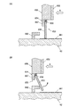
接離検出手段の他の構成としては、例えば図22(A)及び図22(B)に示すように、突き当て部材650における印刷指U1が突き当たる側の面に印刷指U1の先端部によって押し込まれることでON状態となるタクトスイッチ671等のプッシュスイッチを設けてもよい。この場合、図22(A)に示すように、印刷指U1が突き当て部材650に当接し押し込まれるまではタクトスイッチ671はOFF状態となっている。そして、図22(B)に示すように、印刷指U1の先端部が突き当て部材650に突き当てられてタクトスイッチ671が押し込まれると、タクトスイッチ671がON状態となり、制御部50にON信号が出力される。
また、例えば図23(A)及び図23(B)に示すように、突き当て部材650における印刷指U1が突き当たる側の面に、図22(A)及び図22(B)に示すのと同様に印刷指U1の先端部によって押し込まれることでON状態となるタクトスイッチ673とその表面に設けられ突き当て部材650における印刷指U1が突き当たる面とほぼ平行となるように配置された板状部材674とを備えるスイッチ機構を設けてもよい。この場合、図23(A)に示すように、印刷指U1が突き当て部材650に当接し押し込まれるまではタクトスイッチ673はOFF状態となっている。そして、図23(B)に示すように、印刷指U1の先端部が突き当て部材650に突き当てられ、板状部材674を介してタクトスイッチ673が押し込まれると、タクトスイッチ673がON状態となり、制御部50にON信号が出力される。このような構成とした場合には、タクトスイッチ673をON状態とするために押圧する面積を広くすることができるため、印刷指U1が指挿入部材61に挿入された際に、タクトスイッチ673を確実にON状態とすることができる。
また、タクトスイッチ等の接離検出手段を設ける位置はここに示したものに限定されず、例えば、突き当て部材650の内部に埋め込むように設置したり、突き当て部材650の背後に設置されている構造としてもよい。
As another configuration of the contact / separation detecting means, for example, as shown in FIGS. 22 (A) and 22 (B), the end of the printing finger U1 is pushed into the surface of the abutting member 650 where the printing finger U1 comes into contact. Thus, a push switch such as a tact switch 671 that is turned on may be provided. In this case, as shown in FIG. 22A, the tact switch 671 is in the OFF state until the printing finger U1 comes into contact with the abutting member 650 and is pushed. Then, as shown in FIG. 22B, when the tip of the printing finger U1 is abutted against the abutting member 650 and the tact switch 671 is pushed in, the tact switch 671 is turned on, and an ON signal is sent to the control unit 50. Is output.
Further, for example, as shown in FIGS. 23A and 23B, the surface of the abutting member 650 on the side where the printing finger U1 abuts is the same as that shown in FIGS. 22A and 22B. The tactile switch 673 that is turned on by being pushed by the tip of the printing finger U1 and the plate-like member 674 that is provided on the surface thereof and arranged so as to be substantially parallel to the surface of the abutting member 650 that the printing finger U1 abuts. A switch mechanism including the above may be provided. In this case, as shown in FIG. 23A, the tact switch 673 is in an OFF state until the printing finger U1 comes into contact with and is pushed into the abutting member 650. Then, as shown in FIG. 23B, when the tip of the printing finger U1 is abutted against the abutting member 650 and the tact switch 673 is pushed in via the plate-like member 674, the tact switch 673 is turned on. The ON signal is output to the control unit 50. In such a configuration, since the area to be pressed to turn the tact switch 673 on can be increased, the tact switch 673 is turned on when the printing finger U1 is inserted into the finger insertion member 61. It can be surely turned on.
Further, the position where the contact / separation detecting means such as a tact switch is provided is not limited to the one shown here. For example, the contact / separation detecting means is installed so as to be embedded in the abutting member 650 or behind the abutting member 650. It is good also as a structure.

なお、印刷が行われる際は押し上げ機構625によって指置き部材624が上方に押し上げられるため、接離検出手段が突き当て部材650の上方に配置されていると、例えば印刷指U1の爪部Tの長さが長いような場合に爪部Tの先端部が接離検出手段に突き当たって印刷の際に爪部Tの先端部まで上手く印刷できない等のおそれがある。このため、例えば、図24(A)から図24(C)に示すように、突き当て部材650における印刷指U1が突き当たる側の面の下側寄りに接離検出手段としてのタクトスイッチ675を設けてもよい。この場合、図24(A)に示すように、印刷指U1が突き当て部材650に当接し押し込まれるまではタクトスイッチ675はOFF状態となっている。そして、図23(B)に示すように、印刷指U1の爪部Tの先端部が突き当て部材650に突き当てられ、タクトスイッチ675が押し込まれると、タクトスイッチ675がON状態となり、制御部50にON信号が出力される。このような構成とした場合には、その後、図23(C)に示すように、指置き部材624が上方に押し上げられた際に、爪部Tはタクトスイッチ675よりも上に出るため、タクトスイッチ675が印刷の妨げとならず、また、爪部Tが突き当て部材650と干渉することも防げることから、爪部Tの先端部まで美しく印刷を施すことができる。   When printing is performed, the finger placement member 624 is pushed upward by the push-up mechanism 625. Therefore, when the contact / separation detection unit is disposed above the abutting member 650, for example, the nail T of the printing finger U1 When the length is long, the tip of the nail T may abut against the contact / separation detecting means, and printing may not be performed well up to the tip of the nail T during printing. For this reason, for example, as shown in FIGS. 24A to 24C, a tact switch 675 as a contact / separation detection unit is provided on the lower side of the surface of the abutting member 650 on which the printing finger U1 abuts. May be. In this case, as shown in FIG. 24A, the tact switch 675 is in an OFF state until the printing finger U1 is brought into contact with the abutting member 650 and pushed. Then, as shown in FIG. 23B, when the tip of the nail T of the printing finger U1 is abutted against the abutting member 650 and the tact switch 675 is pushed in, the tact switch 675 is turned on, and the control unit 50, an ON signal is output. In the case of such a configuration, as shown in FIG. 23C, when the finger placing member 624 is pushed upward, the nail portion T comes out above the tact switch 675. Since the switch 675 does not hinder printing, and the claw portion T can also be prevented from interfering with the abutting member 650, printing can be performed up to the tip of the claw portion T.

また、ストッパ機構の構成、ストッパ機構による規制を解除する構成は、本実施形態に示したものに限定されず、他の構成によってもよい。例えば、図25(A)及び図25(B)に示すように、ストッパ機構680を、指挿入方向Aの奥側に弾性を有する係止用突起685を有するストッパ支持部材681と、このストッパ支持部材681に対して回転軸683により軸支されたストッパ部材682とにより構成してもよい。
このような構成とした場合には、指挿入部材を指挿入方向Aの奥側まで押し込んだ際には、ストッパ部材682の固定端側がストッパ支持部材681によって確実に支持されるとともに、ストッパ部材682の下端部(自由端側)とカバー部材62の凹凸部661との摩擦力によって指挿入部材が指挿入方向Aと反対の方向に押し戻されることを防止して、印刷指U1が突き当て部材650から離間した際に、指挿入部材が印刷指U1の動きに追従して接離検出手段である板スイッチ部652のON状態が維持されることを防ぐことができる。
また、ストッパ機構による規制を解除する際には、ストッパ部材682の下端部(自由端側)が規制解除部材662に突き当てられて図25(B)における矢印方向に押し上げられる。図25(A)及び図25(B)に示す構成では、ストッパ部材682は矢印方向に所定量以上回動すると、ストッパ部材682の固定側の端部が弾性を有する係止用突起685を乗り越えて回動状態が維持されるようになっている。これにより、ストッパ部材682による指挿入部材61の移動規制が解除される。
Further, the configuration of the stopper mechanism and the configuration for releasing the restriction by the stopper mechanism are not limited to those shown in the present embodiment, and other configurations may be used. For example, as shown in FIGS. 25A and 25B, the stopper mechanism 680 includes a stopper support member 681 having a locking projection 685 having elasticity on the back side in the finger insertion direction A, and the stopper support. You may comprise with the stopper member 682 pivotally supported by the rotating shaft 683 with respect to the member 681. FIG.
In such a configuration, when the finger insertion member is pushed to the far side in the finger insertion direction A, the fixed end side of the stopper member 682 is reliably supported by the stopper support member 681, and the stopper member 682 is provided. The finger insertion member is prevented from being pushed back in the direction opposite to the finger insertion direction A by the frictional force between the lower end portion (free end side) of the cover member and the concave and convex portion 661 of the cover member 62, and the printing finger U1 is brought into contact with the abutting member 650. It is possible to prevent the ON state of the plate switch portion 652 that is the contact / separation detecting means from being followed by the movement of the printing finger U1 when the finger insertion member is separated from the printing finger U1.
When the restriction by the stopper mechanism is released, the lower end portion (free end side) of the stopper member 682 is abutted against the restriction release member 662 and pushed up in the direction of the arrow in FIG. In the configuration shown in FIGS. 25A and 25B, when the stopper member 682 rotates more than a predetermined amount in the direction of the arrow, the fixed-side end of the stopper member 682 gets over the elastic locking projection 685. The rotation state is maintained. Thereby, the movement restriction | limiting of the finger insertion member 61 by the stopper member 682 is cancelled | released.

なお、ストッパ機構653や規制解除部材662等は、本発明の必須の構成要素ではなく、これを備えない構成としてもよい。   Note that the stopper mechanism 653, the restriction release member 662, and the like are not essential components of the present invention, and may be configured not to include them.

また、本実施形態では、カバー部材62の底面に凹凸部661を設けて、ストッパ部材655は、その下端部とカバー部材62側の凹凸部661との摩擦力により指挿入部材61が移動することを規制する構成としたが、凹凸部661を設けることは必須ではない。ストッパ部材655により指挿入部材61の移動を確実に規制するためには、カバー部材62の底面に何らかの表面加工を施して滑りにくくすることが好ましいが、ストッパ部材655を大きな摩擦力を生ずるような材料で形成する等した場合には、カバー部材62の底面側に滑り止め加工を施さなくてもよい。また、例えばストッパ部材655をカバー部材62の底面方向に押し付けるバネ等を設けて、ストッパ部材655を底面方向に押圧することにより指挿入部材61の移動を確実に規制し得るようにしてもよい。   In the present embodiment, the concave and convex portion 661 is provided on the bottom surface of the cover member 62, and the finger insertion member 61 is moved by the frictional force between the lower end portion of the stopper member 655 and the concave and convex portion 661 on the cover member 62 side. However, it is not essential to provide the uneven portion 661. In order to reliably restrict the movement of the finger insertion member 61 by the stopper member 655, it is preferable to apply some surface processing to the bottom surface of the cover member 62 to make it difficult to slip, but the stopper member 655 generates a large frictional force. In the case where the cover member 62 is made of a material, the bottom surface side of the cover member 62 does not need to be subjected to the anti-slip process. Further, for example, a spring or the like that presses the stopper member 655 toward the bottom surface of the cover member 62 may be provided so that the movement of the finger insertion member 61 can be reliably regulated by pressing the stopper member 655 toward the bottom surface.

また、本実施形態では、ストッパ機構によって指挿入部材61が任意の場所で停止するように構成したが、所定の位置で停止するようにしてもよい。
この場合、複数の印刷指U1を同時にセットする場合には、例えばそのうちの最も長い印刷指U1(一般的には中指)が所定の位置に到達した時点でロックされるようにする。ここで「所定の位置」とは、最も長い印刷指U1(例えば中指)の爪部Tが印刷範囲の奥側に配置されるような位置であり、かつ、他の印刷指U1も全て印刷可能範囲に入るような位置である。
Further, in the present embodiment, the finger insertion member 61 is configured to stop at an arbitrary place by the stopper mechanism, but may be stopped at a predetermined position.
In this case, when a plurality of printing fingers U1 are set simultaneously, for example, the longest printing finger U1 (generally the middle finger) is locked when reaching a predetermined position. Here, the “predetermined position” is a position where the nail portion T of the longest printing finger U1 (for example, the middle finger) is arranged on the back side of the printing range, and all the other printing fingers U1 can be printed. The position is within the range.

また、本実施形態では、1つの装置で1本の印刷指U1のみの印刷、複数本の印刷指U1の印刷の双方に対応可能とし、複数の指挿入部材61を備え、各指挿入部材61に接離検出手段(板スイッチ部やタクトスイッチ)を設ける構成としたが、印刷指U1を1本ずつ印刷する専用の装置であっても本発明を適用することができる。   Further, in the present embodiment, one apparatus can handle both printing of only one printing finger U1 and printing of a plurality of printing fingers U1, and includes a plurality of finger insertion members 61. However, the present invention can also be applied to a dedicated device for printing the printing fingers U1 one by one.

また、本実施形態では、接離検出手段(板スイッチ部やタクトスイッチ)が印刷部40を制御する制御部50に接続され、接離検出手段から出力されたON信号・OFF信号が制御部50に送られ、接離検出手段から信号が出力されたときには制御部50によって印刷開始や印刷中止のための制御が行われる構成としたが、接離検出手段により印刷開始や印刷中止といった印刷部40の動作を切り替える構成はこれに限定されない。例えば接離検出手段を印刷部40を構成する第1モータ43、第2モータ47、印刷ヘッド46等と直接接続し、これらを直接ON/OFFするためのスイッチとして機能させてもよい。   In the present embodiment, the contact / separation detection means (plate switch unit or tact switch) is connected to the control unit 50 that controls the printing unit 40, and the ON signal / OFF signal output from the contact / separation detection unit is the control unit 50. When the signal is output from the contact / separation detection unit, the control unit 50 performs control for starting or stopping printing. However, the printing unit 40 starts or stops printing by the contact / separation detection unit. The configuration for switching the operation is not limited to this. For example, the contact / separation detection means may be directly connected to the first motor 43, the second motor 47, the print head 46, etc. constituting the printing unit 40, and may function as a switch for directly turning on / off these.

その他、本発明が本実施形態に限定されず、適宜変更可能であることはいうまでもない。   In addition, it cannot be overemphasized that this invention is not limited to this embodiment, and can be changed suitably.

以上本発明のいくつかの実施形態を説明したが、本発明の範囲は、上述の実施の形態に限定するものではなく、特許請求の範囲に記載された発明の範囲とその均等の範囲を含む。
以下に、この出願の願書に最初に添付した特許請求の範囲に記載した発明を付記する。付記に記載した請求項の項番は、この出願の願書に最初に添付した特許請求の範囲の通りである。
〔付記〕
<請求項1>
印刷しようとする爪部に対応する指である印刷指を固定可能な印刷指固定部と、この印刷指固定部に固定されている印刷指の爪部にそれぞれ印刷を施す印刷手段と、を備えるネイルプリント装置であって、
前記印刷指固定部は、前記印刷指を1つ挿入可能であって前記印刷指を挿入した際に前記印刷指の長さに応じて指挿入方向に沿ってスライド移動可能に構成された指挿入部材を少なくとも1つ備え、
この指挿入部材は、
前記爪部を露出させる爪部露出窓と、
前記爪部露出窓よりも指挿入方向の手前側に配置され、前記印刷指を挿入した際に前記爪部の生え際近傍を上方から押さえる指押え部と、
前記爪部露出窓よりも指挿入方向の奥側に配置され、前記印刷指を挿入した際に前記印刷指の先端部が突き当たる突き当て部材と、
を備えていることを特徴とするネイルプリント装置。
<請求項2>
前記印刷指固定部は、前記指挿入部材に対応する位置に前記指挿入部材内に前記印刷指が挿入された際に前記指挿入部材を前記印刷指の挿入方向に案内するガイド部を備えていることを特徴とする請求項1に記載のネイルプリント装置。
<請求項3>
前記印刷指固定部は、前記指挿入部材を少なくとも1つ収容し前記爪部露出窓に対応する位置に開口部を有するカバー部材をさらに備え、
前記ガイド部は、前記カバー部材に設けられていることを特徴とする請求項2に記載のネイルプリント装置。
<請求項4>
前記指挿入部材は下側が開口しており、この開口した指挿入部材の下方に配置され、前記指挿入部材に挿入された前記印刷指を下方から保持する指置き部材をさらに備えていることを特徴とする請求項1から請求項3のいずれか一項に記載のネイルプリント装置。
<請求項5>
前記指置き部材を下方から押し上げる押し上げ機構をさらに備えていることを特徴とする請求項4に記載のネイルプリント装置。
<請求項6>
前記印刷指固定部に固定されている印刷指を撮影して指爪画像を取得する撮影手段と、
この撮影手段で撮影された指爪画像を表示させる表示手段と、
をさらに備えていることを特徴とする請求項1から請求項5のいずれか一項に記載のネイルプリント装置。
<請求項7>
前記突き当て部材における前記印刷指の先端部が突き当たる側に設けられ、前記印刷指の前記突き当て部材に対する接離を検出する接離検出手段と、
この接離検出手段により前記印刷指が前記突き当て部材に接していると検出されると、接触検出時又はこの接触検出時から所定の時間経過後に前記爪部への印刷動作を開始し、印刷動作開始後に、この接離検出手段により前記印刷指の前記突き当て部材からの離間が検出されると、前記爪部への印刷動作を停止させるように、前記印刷手段を制御する印刷制御手段と、
をさらに備えていることを特徴とする請求項1から請求項6のいずれか一項に記載のネイルプリント装置。
<請求項8>
前記指挿入部材は、複数の印刷指に対応して複数設けられており、
前記接離検出手段は、複数の前記指挿入部材における前記突き当て部材にそれぞれ設けられ、
前記印刷制御手段は、前記指挿入部材のうち印刷指が挿入されたものに設けられている全ての前記接離検出手段により前記印刷指が前記突き当て部材に接していると検出されると、接触検出時又はこの接触検出時から所定の時間経過後に前記爪部への印刷動作を開始し、印刷動作開始後に、これらの接離検出手段のうちの少なくとも1つにより前記印刷指の前記突き当て部材からの離間が検出されると、前記爪部への印刷動作を停止させるように、前記印刷手段を制御するものであることを特徴とする請求項7に記載のネイルプリント装置。
<請求項9>
前記指挿入部材は、前記指挿入部材が指挿入方向に沿ってスライド移動した際に、これと反対の方向に前記指挿入部材が移動することを規制する逆移動規制部材を備えており、
前記印刷指固定部は、逆移動規制部材を解除する規制解除部材を備えていることを特徴とする請求項7又は請求項8に記載のネイルプリント装置。
Although several embodiments of the present invention have been described above, the scope of the present invention is not limited to the above-described embodiments, but includes the scope of the invention described in the claims and equivalents thereof. .
The invention described in the scope of claims attached to the application of this application will be added below. The item numbers of the claims described in the appendix are as set forth in the claims attached to the application of this application.
[Appendix]
<Claim 1>
A printing finger fixing unit capable of fixing a printing finger, which is a finger corresponding to the nail unit to be printed, and a printing unit that performs printing on each of the nail portions of the printing finger fixed to the printing finger fixing unit. A nail printing device,
The printing finger fixing unit is configured to insert one printing finger, and when the printing finger is inserted, the finger insertion is configured to be slidable along a finger insertion direction according to the length of the printing finger. Comprising at least one member,
This finger insertion member
A nail part exposure window for exposing the nail part;
A finger presser that is arranged on the near side in the finger insertion direction from the nail part exposure window and presses the vicinity of the hairline of the nail part from above when the printing finger is inserted;
An abutting member that is disposed on the back side in the finger insertion direction from the nail part exposure window, and a tip part of the printing finger abuts when the printing finger is inserted,
A nail printing apparatus comprising:
<Claim 2>
The printing finger fixing unit includes a guide unit that guides the finger insertion member in the insertion direction of the printing finger when the printing finger is inserted into the finger insertion member at a position corresponding to the finger insertion member. The nail printing apparatus according to claim 1, wherein the nail printing apparatus is provided.
<Claim 3>
The printing finger fixing part further includes a cover member that houses at least one finger insertion member and has an opening at a position corresponding to the nail part exposure window,
The nail printing apparatus according to claim 2, wherein the guide portion is provided on the cover member.
<Claim 4>
The finger insertion member has an opening on the lower side, and is further provided with a finger placement member that is disposed below the opened finger insertion member and holds the printing finger inserted into the finger insertion member from below. The nail print apparatus according to any one of claims 1 to 3, wherein the nail print apparatus is characterized.
<Claim 5>
The nail printing apparatus according to claim 4, further comprising a push-up mechanism that pushes up the finger placement member from below.
<Claim 6>
Imaging means for capturing a fingernail image by photographing a printing finger fixed to the printing finger fixing unit;
Display means for displaying a fingernail image photographed by the photographing means;
The nail printing apparatus according to any one of claims 1 to 5, further comprising:
<Claim 7>
A contact / separation detection means for detecting contact / separation of the printing finger with respect to the abutting member, provided on a side where a tip of the printing finger abuts on the abutting member;
When it is detected by the contact / separation detecting means that the printing finger is in contact with the abutting member, the printing operation to the nail portion is started at the time of contact detection or after a predetermined time has elapsed from the time of contact detection. A printing control means for controlling the printing means so as to stop the printing operation on the nail portion when the contact of the printing finger from the abutting member is detected by the contact / separation detection means after the start of the operation; ,
The nail printing apparatus according to any one of claims 1 to 6, further comprising:
<Claim 8>
A plurality of the finger insertion members are provided corresponding to a plurality of printing fingers,
The contact / separation detecting means is provided on each of the abutting members of the plurality of finger insertion members,
When the printing control unit detects that the printing finger is in contact with the abutting member by all the contact / separation detection units provided in the finger insertion member into which the printing finger is inserted, When the contact is detected or after a predetermined time has elapsed since the contact is detected, the printing operation to the nail portion is started. After the printing operation is started, the abutment of the printing finger by at least one of these contact / separation detection means 8. The nail printing apparatus according to claim 7, wherein when the separation from the member is detected, the printing unit is controlled so as to stop the printing operation on the nail portion.
<Claim 9>
The finger insertion member includes a reverse movement restricting member that restricts the finger insertion member from moving in the opposite direction when the finger insertion member slides in the finger insertion direction.
The nail print apparatus according to claim 7, wherein the printing finger fixing portion includes a restriction release member that releases the reverse movement restriction member.

1 ネイルプリント装置
2 ケース本体
4 蓋体
12 操作部
13 表示部
20a 指固定ユニット収容部
20b 非印刷指挿入部
20c 掴み部(隔壁)
20 印刷指固定部
30 撮影部
32 カメラ
33 照明灯(LED)
40 印刷部
46 印刷ヘッド
50 制御部
60 印刷指固定ユニット
61 指挿入部材
62 カバー部材
611 爪部露出窓
612 指押え部
613 突き当て部材
621 爪部露出用開口部
622 ガイド溝
623 凹部
624 指置き部材
625 押し上げ機構
650 突き当て部材
652 板スイッチ部
653 ストッパ機構
655 ストッパ部材
662 規制解除部材
A 指挿入方向
T 爪
U1 印刷指
DESCRIPTION OF SYMBOLS 1 Nail printing apparatus 2 Case main body 4 Cover body 12 Operation part 13 Display part 20a Finger fixing unit accommodating part 20b Non-printing finger insertion part 20c Grasp part (partition wall)
20 Printing Finger Fixing Unit 30 Imaging Unit 32 Camera 33 Illumination Light (LED)
40 printing unit 46 printing head 50 control unit 60 printing finger fixing unit 61 finger insertion member 62 cover member 611 nail part exposure window 612 finger pressing part 613 abutting member 621 nail part exposure opening 622 guide groove 623 recess 624 finger placing member 625 Push-up mechanism 650 Abutting member 652 Plate switch part 653 Stopper mechanism 655 Stopper member 662 Restriction release member A Finger insertion direction T Claw U1 Printing finger

Claims (11)

印刷しようとする爪部に対応する指である印刷指を固定可能な印刷指固定部と、
前記印刷指固定部に固定されている前記印刷指の爪部にインクを塗布する印刷ヘッドを有する印刷部と、
を備え、
前記印刷指固定部は、1つの前記印刷指を挿入可能に構成された指挿入部材を少なくとも1つ備え、
前記指挿入部材は、
前記印刷指が挿入された際に、前記印刷指の前記爪部が形成されている側の上部に設けられ、前記印刷指が挿入された際の該印刷指の前記爪部に対応する位置に設けられた開口部により形成された、前記爪部を露出する爪部露出窓を有し、前記爪部露出窓を除く領域が前記印刷指の前記爪部を除く領域の少なくとも一部を覆っている指押え部と、
前記印刷指が挿入された際に、前記印刷指の前記爪部が形成されている側の反対側に設けられ、前記印刷指を、該印刷指の前記爪部が形成されている側が前記指押え部に接するまで押し上げる押し上げ機構と、
前記印刷指が挿入される際に前記印刷指の先端部に突き当たり、前記印刷指の挿入に応じて、前記印刷指の先端部に接した状態で前記印刷指の挿入方向の奥側に移動する突き当て部材と、
を備え
前記指押さえ部は、前記爪部露出窓と該爪部露出窓を除く領域とが、前記突き当て部材と同じ方向に、該突き当て部材と連動して移動することを特徴とするネイルプリント装置。
A printing finger fixing part capable of fixing a printing finger which is a finger corresponding to the nail part to be printed;
A printing unit having a print head for applying ink to the nail portion of the printing finger fixed to the printing finger fixing unit;
With
The printing finger fixing unit includes at least one finger insertion member configured to be able to insert one printing finger,
The finger insertion member is
When the printing finger is inserted, the printing finger is provided at an upper portion on the side where the nail portion is formed, and is located at a position corresponding to the nail portion of the printing finger when the printing finger is inserted. The nail part exposure window which exposes the nail part formed by the provided opening part is provided, and the area excluding the nail part exposure window covers at least a part of the area excluding the nail part of the printing finger. A finger presser
When the printing finger is inserted, the printing finger is provided on the side opposite to the side where the nail portion is formed, and the printing finger is placed on the side where the nail portion of the printing finger is formed. A push-up mechanism that pushes up until the presser part comes
When the printing finger is inserted, it strikes the tip of the printing finger and moves to the back side in the insertion direction of the printing finger in contact with the tip of the printing finger according to the insertion of the printing finger. An abutting member;
Equipped with a,
In the nail print apparatus , the finger pressing unit moves the nail part exposure window and the region excluding the nail part exposure window in the same direction as the abutting member in conjunction with the abutting member. .
前記指押え部は前記突き当て部材と一体に形成されていることを特徴とする請求項に記載のネイルプリント装置。The nail print apparatus according to claim 1 , wherein the finger press portion is formed integrally with the abutting member. 前記指挿入部材は、前記突き当て部材を前記印刷指が挿入される方向と逆の向きに付勢する弾性部材を有することを特徴とする請求項2に記載のネイルプリント装置。   The nail printing apparatus according to claim 2, wherein the finger insertion member includes an elastic member that urges the abutting member in a direction opposite to a direction in which the printing finger is inserted. 前記突き当て部材における前記印刷指の先端部が突き当たる側に設けられ、前記印刷指の前記突き当て部材に対する接離を検出する接離検出手段と、
前記接離検出手段により前記印刷指が前記突き当て部材に接していると検出されると、接触検出時又はこの接触検出時から所定の時間経過後に前記爪部への印刷動作を開始し、印刷動作開始後に、この接離検出手段により前記印刷指の前記突き当て部材からの離間が検出されると、前記爪部への印刷動作を停止させるように、前記印刷手段を制御する印刷制御手段と、
をさらに備えていることを特徴とする請求項に記載のネイルプリント装置。
A contact / separation detection means for detecting contact / separation of the printing finger with respect to the abutting member, provided on a side where a tip of the printing finger abuts on the abutting member;
When it is detected by the contact / separation detection means that the printing finger is in contact with the abutting member, the printing operation to the nail portion is started at the time of contact detection or after a predetermined time has elapsed from the time of contact detection, and printing is performed. A printing control means for controlling the printing means so as to stop the printing operation on the nail portion when the contact of the printing finger from the abutting member is detected by the contact / separation detection means after the start of the operation; ,
The nail printing apparatus according to claim 1 , further comprising:
前記指挿入部材は、複数の印刷指に対応して複数設けられており、
前記接離検出手段は、複数の前記指挿入部材における前記突き当て部材にそれぞれ設けられ、
前記印刷制御手段は、前記指挿入部材のうち印刷指が挿入されたものに設けられている全ての前記接離検出手段により前記印刷指が前記突き当て部材に接していると検出されると、接触検出時又はこの接触検出時から所定の時間経過後に前記爪部への印刷動作を開始し、印刷動作開始後に、これらの接離検出手段のうちの少なくとも1つにより前記印刷指の前記突き当て部材からの離間が検出されると、前記爪部への印刷動作を停止させるように、前記印刷手段を制御するものであることを特徴とする請求項に記載のネイルプリント装置。
A plurality of the finger insertion members are provided corresponding to a plurality of printing fingers,
The contact / separation detecting means is provided on each of the abutting members of the plurality of finger insertion members,
When the printing control unit detects that the printing finger is in contact with the abutting member by all the contact / separation detection units provided in the finger insertion member into which the printing finger is inserted, When the contact is detected or after a predetermined time has elapsed since the contact is detected, the printing operation to the nail portion is started. After the printing operation is started, the abutment of the printing finger by at least one of these contact / separation detection means 5. The nail printing apparatus according to claim 4 , wherein when the separation from the member is detected, the printing unit is controlled so as to stop the printing operation on the nail portion.
前記指挿入部材は、前記指挿入部材が指挿入方向に沿ってスライド移動した際に、これと反対の方向に前記指挿入部材が移動することを規制する逆移動規制部材を備えており、
前記印刷指固定部は、逆移動規制部材を解除する規制解除部材を備えていることを特徴とする請求項1から請求項5のいずれか一項に記載のネイルプリント装置。
The finger insertion member includes a reverse movement restricting member that restricts the finger insertion member from moving in the opposite direction when the finger insertion member slides in the finger insertion direction.
The printing finger fixing unit, nail printing device according to any one of claims 1 to 5, characterized in that it comprises a restriction releasing member for releasing the reverse movement restricting member.
前記印刷指固定部は、前記指挿入部材内に前記印刷指が挿入される際の前記突き当て部材の移動に対応して、前記指挿入部材を前記印刷指の挿入方向に案内するガイド部を、前記指挿入部材に対応する位置に備えていることを特徴とする請求項から請求項のいずれか一項に記載のネイルプリント装置。 The printing finger fixing portion includes a guide portion that guides the finger insertion member in the insertion direction of the printing finger in response to the movement of the abutting member when the printing finger is inserted into the finger insertion member. , nail printing device according to any one of claims 1 to 6, characterized in that it comprises a position corresponding to the finger insertion member. 前記印刷指固定部は、前記指挿入部材を少なくとも1つ収容し前記爪部露出窓に対応する位置に開口部を有するカバー部材をさらに備え、
前記ガイド部は、前記カバー部材に設けられていることを特徴とする請求項に記載のネイルプリント装置。
The printing finger fixing part further includes a cover member that houses at least one finger insertion member and has an opening at a position corresponding to the nail part exposure window,
The nail printing apparatus according to claim 7 , wherein the guide portion is provided on the cover member.
前記指挿入部材内に挿入される前記印刷指の前記爪部が形成されている側と反対側の面と前記押し上げ機構との間に設けられ、前記指挿入部材に挿入された前記印刷指を前記爪部が形成されている側と反対側の面から保持する指置き部材をさらに備えていることを特徴とする請求項1から請求項のいずれか一項に記載のネイルプリント装置。 The printing finger inserted into the finger insertion member is provided between the surface of the printing finger inserted into the finger insertion member on the opposite side to the side where the nail portion is formed and the push-up mechanism. The nail printing apparatus according to any one of claims 1 to 8 , further comprising a finger placement member that is held from a surface opposite to a side on which the claw portion is formed. 前記指置き部材は、樹脂材料を含む弾性部材であることを特徴とする請求項に記載のネイルプリント装置。 The nail print apparatus according to claim 9 , wherein the finger placement member is an elastic member including a resin material. 前記印刷指固定部に固定されている印刷指を撮影して指爪画像を取得する撮影手段と、
この撮影手段で撮影された指爪画像を表示させる表示手段と、
をさらに備えていることを特徴とする請求項1から請求項10のいずれか一項に記載のネイルプリント装置。
Imaging means for capturing a fingernail image by photographing a printing finger fixed to the printing finger fixing unit;
Display means for displaying a fingernail image photographed by the photographing means;
The nail printing apparatus according to any one of claims 1 to 10 , further comprising:
JP2011079684A 2010-12-10 2011-03-31 Nail printing device Active JP5348168B2 (en)

Priority Applications (3)

Application Number Priority Date Filing Date Title
JP2011079684A JP5348168B2 (en) 2010-12-10 2011-03-31 Nail printing device
US13/315,668 US8721068B2 (en) 2010-12-10 2011-12-09 Nail print apparatus
CN201110408200.7A CN102529355B (en) 2010-12-10 2011-12-09 Nail print apparatus

Applications Claiming Priority (3)

Application Number Priority Date Filing Date Title
JP2010275258 2010-12-10
JP2011079684A JP5348168B2 (en) 2010-12-10 2011-03-31 Nail printing device

Publications (3)

Publication Number Publication Date
JP2012135600A JP2012135600A (en) 2012-07-19
JP2012135600A5 JP2012135600A5 (en) 2012-08-30
JP5348168B2 true JP5348168B2 (en) 2013-11-20

Family

ID=46198958

Family Applications (1)

Application Number Title Priority Date Filing Date
JP2011079684A Active JP5348168B2 (en) 2010-12-10 2011-03-31 Nail printing device

Country Status (3)

Country Link
US (1) US8721068B2 (en)
JP (1) JP5348168B2 (en)
CN (1) CN102529355B (en)

Families Citing this family (46)

* Cited by examiner, † Cited by third party
Publication number Priority date Publication date Assignee Title
JP5402980B2 (en) * 2011-05-09 2014-01-29 カシオ計算機株式会社 Nail printing apparatus and printing control method for nail printing apparatus
JP5633530B2 (en) * 2012-03-21 2014-12-03 カシオ計算機株式会社 Nail printing device
JP6186975B2 (en) * 2012-09-06 2017-08-30 カシオ計算機株式会社 Nail printing apparatus and printing control method for nail printing apparatus
JP5831428B2 (en) * 2012-11-09 2015-12-09 カシオ計算機株式会社 Nail printing apparatus and printing control method for nail printing apparatus
JP5915571B2 (en) * 2013-03-14 2016-05-11 カシオ計算機株式会社 Nail printing apparatus and printing method for nail printing apparatus
US9687059B2 (en) * 2013-08-23 2017-06-27 Preemadonna Inc. Nail decorating apparatus
US11265444B2 (en) * 2013-08-23 2022-03-01 Preemadonna Inc. Apparatus for applying coating to nails
JP6206346B2 (en) * 2014-06-30 2017-10-04 カシオ計算機株式会社 Drawing apparatus and drawing control method of drawing apparatus
JP6561462B2 (en) * 2014-12-19 2019-08-21 カシオ計算機株式会社 Nail printing apparatus and drawing method of nail printing apparatus
JP6561463B2 (en) * 2014-12-25 2019-08-21 カシオ計算機株式会社 Drawing apparatus, drawing apparatus operation control method, and drawing apparatus operation control program
JP6577203B2 (en) * 2015-02-17 2019-09-18 株式会社アゲハ Fingertip holder for nail art print, fingertip holder placement device, and nail art print device
JP6733135B2 (en) 2015-06-18 2020-07-29 カシオ計算機株式会社 Drawing device
JP6947252B2 (en) * 2015-06-18 2021-10-13 カシオ計算機株式会社 Drawing device
JP6699100B2 (en) * 2015-06-22 2020-05-27 カシオ計算機株式会社 Drawing device
JP6493015B2 (en) * 2015-06-26 2019-04-03 カシオ計算機株式会社 Drawing apparatus, drawing apparatus operation control method, and drawing apparatus operation control program
JP2017006570A (en) 2015-06-26 2017-01-12 カシオ計算機株式会社 Drawing device
EP3121019B1 (en) * 2015-07-09 2020-01-01 Funai Electric Co., Ltd. Ejection device
US9789683B2 (en) * 2015-07-09 2017-10-17 Funai Electric Co., Ltd. Ejection device
JP6808935B2 (en) * 2015-12-25 2021-01-06 カシオ計算機株式会社 Drawing device and drawing method
JP6808936B2 (en) * 2015-12-28 2021-01-06 カシオ計算機株式会社 Drawing device and control method of drawing device
JP6504047B2 (en) * 2015-12-28 2019-04-24 カシオ計算機株式会社 Drawing device
CN105639987B (en) * 2016-03-17 2018-11-27 徐州工程学院 To the support device of the modification of toe deck or its surface deposit fluid
JP6680112B2 (en) * 2016-06-30 2020-04-15 カシオ計算機株式会社 Finger fixing unit and drawing device
JP6880619B2 (en) * 2016-09-27 2021-06-02 カシオ計算機株式会社 Finger holding member and drawing device
CN106889741B (en) * 2017-05-09 2021-01-19 苏州衡创信息科技有限公司 Portable intelligent nail printer
JP6969173B2 (en) * 2017-06-16 2021-11-24 カシオ計算機株式会社 Drawing device
JP6926795B2 (en) 2017-08-04 2021-08-25 カシオ計算機株式会社 Nail printing device
WO2019070886A1 (en) 2017-10-04 2019-04-11 Preemadonna Inc. Systems and methods of adaptive nail printing and collaborative beauty platform hosting
JP7067036B2 (en) * 2017-11-30 2022-05-16 カシオ計算機株式会社 Drawing device and control method of drawing device
CN107898104A (en) * 2017-12-29 2018-04-13 深圳市邻友通科技发展有限公司 Finger fixed structure and nail beauty machine
JP7087818B2 (en) * 2018-08-22 2022-06-21 船井電機株式会社 Finger nail printer
JP6977693B2 (en) * 2018-10-04 2021-12-08 カシオ計算機株式会社 Printing equipment and printing method
CN111000357B (en) * 2018-10-04 2023-01-03 卡西欧计算机株式会社 Nail print apparatus, nail print method, and recording medium
EP3873293A4 (en) * 2018-10-31 2022-08-03 Bilge, Ismail Nail polish machine that can be applied and dried on 5 fingers simultaneously
CA3131318A1 (en) * 2019-02-26 2020-09-03 Elementree Inc. Automatic nail polish application system and method
JP6973437B2 (en) 2019-03-25 2021-11-24 カシオ計算機株式会社 Printing equipment, printing methods and programs
JP2021045502A (en) * 2019-09-20 2021-03-25 カシオ計算機株式会社 Printer, printing method and program
US20240074560A1 (en) 2019-10-29 2024-03-07 NailPro, Inc. Automated total nail care systems, devices and methods
CN112022167A (en) * 2020-09-11 2020-12-04 无锡轲虎医疗科技有限责任公司 Noninvasive blood glucose detection method based on spectral sensor
CN112674453B (en) * 2021-01-08 2023-03-07 上海魅奈儿科技有限公司 Finger support mechanism, hand groove device of nail art and nail art
CN112690552B (en) * 2021-01-08 2023-03-07 上海魅奈儿科技有限公司 Finger positioning device, nail art machine, finger positioning method and nail art method
CN112617381B (en) * 2021-01-08 2022-11-18 上海魅奈儿科技有限公司 Hand support of nail machine, hand groove device of nail machine and nail machine
CN112674452B (en) * 2021-01-08 2023-06-09 上海魅奈儿科技有限公司 Hand slot device of nail machine and nail machine
CN112586859B (en) * 2021-01-08 2023-03-10 上海魅奈儿科技有限公司 Hand groove device of nail machine and nail machine
JP2022150869A (en) * 2021-03-26 2022-10-07 キヤノン株式会社 Recording device and control method
JP2022159726A (en) * 2021-04-05 2022-10-18 キヤノン株式会社 Nail recording unit

Family Cites Families (7)

* Cited by examiner, † Cited by third party
Publication number Priority date Publication date Assignee Title
KR100317845B1 (en) * 1997-12-24 2002-01-18 이시자까 마사또 Nail art method and device
US5931166A (en) * 1998-12-22 1999-08-03 Weber; Paul J. Fingernail decorating
JP3016147B1 (en) * 1998-12-25 2000-03-06 株式会社アトラス Nail art equipment
CN2533707Y (en) * 2002-01-25 2003-02-05 曾进财 Finger nail cosmetic coloured drawing device
CN2547180Y (en) * 2002-05-31 2003-04-30 徐伟军 Machine for colour drawing on finger nail
EP1538942A2 (en) * 2002-08-02 2005-06-15 Conair Corporation Nail care system
JP2006255196A (en) * 2005-03-17 2006-09-28 Seiko Epson Corp Nail drawing device and nail drawing method

Also Published As

Publication number Publication date
JP2012135600A (en) 2012-07-19
US8721068B2 (en) 2014-05-13
CN102529355B (en) 2015-03-11
CN102529355A (en) 2012-07-04
US20120147113A1 (en) 2012-06-14

Similar Documents

Publication Publication Date Title
JP5348168B2 (en) Nail printing device
JP6577203B2 (en) Fingertip holder for nail art print, fingertip holder placement device, and nail art print device
JP5915571B2 (en) Nail printing apparatus and printing method for nail printing apparatus
JP5141756B2 (en) Nail printing device
JP6915396B2 (en) Drawing system, drawing device and terminal device
JP2012135600A5 (en)
JP5728885B2 (en) Nail printing apparatus and printing control method
JP7192916B2 (en) Drawing device, drawing method and program
JP2012245079A (en) Nail printing device and printing control method
CN111000358B (en) Printing apparatus and printing method
KR100579533B1 (en) The printing device for nail art
JP2014124230A (en) Nail printing device, and printing method for the same
JP7375966B2 (en) printing device
JP5991401B2 (en) Nail printing apparatus and printing control method
JP7161693B2 (en) PORTABLE IMAGE FORMING APPARATUS JIG, PORTABLE IMAGE FORMING SYSTEM AND PORTABLE IMAGE FORMING APPARATUS JIG SET
CN109383136B (en) Nail printing device
JP4992999B2 (en) Nail printing device
JP4993001B2 (en) Nail printing device
JP2022159727A (en) Nail recording unit
JP7161702B2 (en) Jig for Portable Image Forming Apparatus and Portable Image Forming System
JP2020055122A (en) Portable image forming device and portable image forming device main body
JP2023091793A (en) Printing device
US20220314638A1 (en) Nail printing apparatus
JP7067166B2 (en) Nail printing device, finger type determination method and program
JP2023079949A (en) recording device

Legal Events

Date Code Title Description
A521 Request for written amendment filed

Free format text: JAPANESE INTERMEDIATE CODE: A523

Effective date: 20120613

A621 Written request for application examination

Free format text: JAPANESE INTERMEDIATE CODE: A621

Effective date: 20120613

A977 Report on retrieval

Free format text: JAPANESE INTERMEDIATE CODE: A971007

Effective date: 20121225

A131 Notification of reasons for refusal

Free format text: JAPANESE INTERMEDIATE CODE: A131

Effective date: 20130108

A521 Request for written amendment filed

Free format text: JAPANESE INTERMEDIATE CODE: A523

Effective date: 20130311

TRDD Decision of grant or rejection written
A01 Written decision to grant a patent or to grant a registration (utility model)

Free format text: JAPANESE INTERMEDIATE CODE: A01

Effective date: 20130723

A61 First payment of annual fees (during grant procedure)

Free format text: JAPANESE INTERMEDIATE CODE: A61

Effective date: 20130805

R150 Certificate of patent or registration of utility model

Ref document number: 5348168

Country of ref document: JP

Free format text: JAPANESE INTERMEDIATE CODE: R150

Free format text: JAPANESE INTERMEDIATE CODE: R150