JP5347971B2 - Sphere-shaped sealing body and method for manufacturing the same - Google Patents
Sphere-shaped sealing body and method for manufacturing the same Download PDFInfo
- Publication number
- JP5347971B2 JP5347971B2 JP2009546145A JP2009546145A JP5347971B2 JP 5347971 B2 JP5347971 B2 JP 5347971B2 JP 2009546145 A JP2009546145 A JP 2009546145A JP 2009546145 A JP2009546145 A JP 2009546145A JP 5347971 B2 JP5347971 B2 JP 5347971B2
- Authority
- JP
- Japan
- Prior art keywords
- outer layer
- heat
- weight
- spherical
- reinforcing material
- Prior art date
- Legal status (The legal status is an assumption and is not a legal conclusion. Google has not performed a legal analysis and makes no representation as to the accuracy of the status listed.)
- Active
Links
Images


Classifications
-
- F—MECHANICAL ENGINEERING; LIGHTING; HEATING; WEAPONS; BLASTING
- F16—ENGINEERING ELEMENTS AND UNITS; GENERAL MEASURES FOR PRODUCING AND MAINTAINING EFFECTIVE FUNCTIONING OF MACHINES OR INSTALLATIONS; THERMAL INSULATION IN GENERAL
- F16J—PISTONS; CYLINDERS; SEALINGS
- F16J15/00—Sealings
- F16J15/02—Sealings between relatively-stationary surfaces
- F16J15/06—Sealings between relatively-stationary surfaces with solid packing compressed between sealing surfaces
- F16J15/10—Sealings between relatively-stationary surfaces with solid packing compressed between sealing surfaces with non-metallic packing
- F16J15/12—Sealings between relatively-stationary surfaces with solid packing compressed between sealing surfaces with non-metallic packing with metal reinforcement or covering
- F16J15/121—Sealings between relatively-stationary surfaces with solid packing compressed between sealing surfaces with non-metallic packing with metal reinforcement or covering with metal reinforcement
- F16J15/126—Sealings between relatively-stationary surfaces with solid packing compressed between sealing surfaces with non-metallic packing with metal reinforcement or covering with metal reinforcement consisting of additions, e.g. metallic fibres, metallic powders, randomly dispersed in the packing
-
- F—MECHANICAL ENGINEERING; LIGHTING; HEATING; WEAPONS; BLASTING
- F01—MACHINES OR ENGINES IN GENERAL; ENGINE PLANTS IN GENERAL; STEAM ENGINES
- F01N—GAS-FLOW SILENCERS OR EXHAUST APPARATUS FOR MACHINES OR ENGINES IN GENERAL; GAS-FLOW SILENCERS OR EXHAUST APPARATUS FOR INTERNAL COMBUSTION ENGINES
- F01N13/00—Exhaust or silencing apparatus characterised by constructional features ; Exhaust or silencing apparatus, or parts thereof, having pertinent characteristics not provided for in, or of interest apart from, groups F01N1/00 - F01N5/00, F01N9/00, F01N11/00
- F01N13/18—Construction facilitating manufacture, assembly, or disassembly
- F01N13/1805—Fixing exhaust manifolds, exhaust pipes or pipe sections to each other, to engine or to vehicle body
- F01N13/1827—Sealings specially adapted for exhaust systems
-
- F—MECHANICAL ENGINEERING; LIGHTING; HEATING; WEAPONS; BLASTING
- F16—ENGINEERING ELEMENTS AND UNITS; GENERAL MEASURES FOR PRODUCING AND MAINTAINING EFFECTIVE FUNCTIONING OF MACHINES OR INSTALLATIONS; THERMAL INSULATION IN GENERAL
- F16L—PIPES; JOINTS OR FITTINGS FOR PIPES; SUPPORTS FOR PIPES, CABLES OR PROTECTIVE TUBING; MEANS FOR THERMAL INSULATION IN GENERAL
- F16L27/00—Adjustable joints, Joints allowing movement
- F16L27/02—Universal joints, i.e. with mechanical connection allowing angular movement or adjustment of the axes of the parts in any direction
- F16L27/04—Universal joints, i.e. with mechanical connection allowing angular movement or adjustment of the axes of the parts in any direction with partly spherical engaging surfaces
- F16L27/06—Universal joints, i.e. with mechanical connection allowing angular movement or adjustment of the axes of the parts in any direction with partly spherical engaging surfaces with special sealing means between the engaging surfaces
- F16L27/073—Universal joints, i.e. with mechanical connection allowing angular movement or adjustment of the axes of the parts in any direction with partly spherical engaging surfaces with special sealing means between the engaging surfaces one of the cooperating surfaces forming the sealing means
-
- F—MECHANICAL ENGINEERING; LIGHTING; HEATING; WEAPONS; BLASTING
- F01—MACHINES OR ENGINES IN GENERAL; ENGINE PLANTS IN GENERAL; STEAM ENGINES
- F01N—GAS-FLOW SILENCERS OR EXHAUST APPARATUS FOR MACHINES OR ENGINES IN GENERAL; GAS-FLOW SILENCERS OR EXHAUST APPARATUS FOR INTERNAL COMBUSTION ENGINES
- F01N2530/00—Selection of materials for tubes, chambers or housings
- F01N2530/18—Plastics material, e.g. polyester resin
- F01N2530/20—Plastics material, e.g. polyester resin reinforced with mineral or metallic fibres
Abstract
Description
本発明は、自動車排気管の球面管継手に使用される球帯状シール体及びその製造方法に関する。 The present invention relates to a ball-shaped seal body used for a spherical pipe joint of an automobile exhaust pipe and a manufacturing method thereof.
近年の自動車は、車両から排出される排気ガスの浄化のためにキャタライザなどの排気浄化装置を組込んだ排気装置を採用されており、自動車用エンジンの排気ガスは、図34に示す後方排気形式の横置きエンジンの排気装置のように、一般的にエキゾーストマニフォールド500に導かれキャタリススティクコンバーター501、エキゾーストパイプ(排気管)502、プリチャンバー503、サイレンサー504を経てテールパイプ505より大気中に放出される。上記排気装置における排気浄化装置は重量物であり、このことから排気浄化装置が振動系のマスを構成して騒音などの問題を引き起こす要因になることから、この排気装置の振動を吸収するためにフレキシブルジョイント、例えば球面管継手を排気装置の所要箇所に配置して振動を吸収するなどの手段が講じられている。
A recent automobile employs an exhaust device incorporating an exhaust purification device such as a catalyzer for purification of exhaust gas exhausted from the vehicle. The exhaust gas of the automobile engine is a rear exhaust type as shown in FIG. In general, the exhaust system of the horizontal engine is guided to the
特許文献1に記載されている球面管継手に使用されるシール体は、耐熱性を有し、相手材とのなじみ性に優れ、また衝撃強度も著しく改善されているという利点を有する反面、乾燥摩擦(ドライ)条件下での摺動摩擦時において往々にして摩擦異常音を発生するという欠点がある。
The sealing body used for the spherical pipe joint described in
上記特許文献1に記載されたシール体の欠点を解消するものとして、本出願人は特許文献2及び特許文献3に記載されたシール体を提案した。このシール体600は、図35及び図36に示すように、円筒内面601、部分凸球面状面602並びに部分凸球面状面602の外径側及び小径側の環状端面603及び604により規定された球帯状基体605と、球帯状基体605の部分凸球面状面602に一体的に形成された外層606とを備えている。球帯状基体605は、金網からなる補強材607と、該補強材607の金網の網目を充填し、かつ補強材607と混在一体化されていると共に圧縮された膨張黒鉛を含む耐熱材608とを具備しており、外層606は、潤滑材609及び耐熱材610と金網からなる補強材611とが圧縮されて補強材611の金網の網目に潤滑材609及び耐熱材610が充填されて当該潤滑材609及び耐熱材610と補強材611とが混在一体化されており、外層606の外表面612は、補強材611からなる面613と潤滑材609からなる面614とが混在した平滑な滑り面となっている。
In order to eliminate the drawbacks of the sealing body described in
上記シール体600の外層606の外表面612は、補強材611からなる面613と潤滑材609からなる面614とが混在した平滑な面となっているため、外表面612と摺接する相手材である排気管の凹球面部との円滑な摺動を確保することができ、また、外表面612と凹球面部との摺動摩擦において、凹球面部の表面に外表面612からの潤滑材609の移着がなされて凹球面部に潤滑材609からなる潤滑被膜を形成する一方、潤滑材609の凹球面部への移着が過度に行われても、外表面612に点在して露出した補強材611が適度な潤滑被膜を残して掻き取る作用を発揮するので、相手材との摺動摩擦においては、相手材の表面に形成された潤滑被膜との摺動摩擦に移行し、摩擦異常音を生じることがないという利点を有するものである。
Since the
特許文献2及び特許文献3に記載されたシール体は上記利点を有するものであるが、該シール体に微小な揺動運動や軸方向の過大な入力が長時間連続して負荷された場合、シール体の外層の表面に露出した金網からなる補強材が相手材表面を攻撃し、アブレッシブ摩耗(ざらつき摩耗)を誘発して相手材表面を損傷させたり、粗面化させたりしてシール性を著しく低下させる虞があり、さらにはアブレッシブ摩耗への移行に伴い、シール体と相手材との摩擦面に堆積した摩耗粉を介しての摩擦に移行し摩擦異常音の発生を誘発させる虞がある。
The seal bodies described in
本発明者らは、相手材との摩擦摺動面となるシール体の外層に着目し、シール体の外層における金網からなる補強材の露出割合、補強材と膨張黒鉛からなる耐熱材との密着度合、補強材の金網を形成する金属細線の線径など、耐熱材と補強材との有機的な関係を見出し、これらの関係を改良することにより上記問題点は解決されるとの知見を得た。 The present inventors pay attention to the outer layer of the sealing body that becomes the friction sliding surface with the counterpart material, the exposed ratio of the reinforcing material made of wire mesh in the outer layer of the sealing body, and the adhesion between the reinforcing material and the heat-resistant material made of expanded graphite. Finding the organic relationship between the heat-resistant material and the reinforcing material, such as the wire diameter of the fine metal wire forming the wire mesh of the reinforcing material, and obtaining knowledge that the above problems can be solved by improving these relationships It was.
本発明は上記知見に基づきなされたものであり、その目的とするところは、相手材との摺動摩擦において、相手材表面を損傷させたり、粗面化させたりすることを極力防止し、シール性の低下及び摩擦異常音の発生を極力防止し得る球帯状シール体及びその製造方法を提供することにある。 The present invention has been made on the basis of the above knowledge, and the object of the present invention is to prevent the surface of the counterpart material from being damaged or roughened in sliding friction with the counterpart material as much as possible. It is an object of the present invention to provide a ball-shaped seal body and a method for manufacturing the same, which can prevent the occurrence of noise reduction and abnormal frictional noise as much as possible.
排気管継手に用いられる本発明の球帯状シール体は、円筒内面、部分凸球面状面並びに部分凸球面状面の大径側及び小径側の環状端面により規定された球帯状基体と、この球帯状基体の部分凸球面状面に一体に形成された外層とを備えていると共に排気管継手に用いられる球帯状シール体であって、球帯状基体は、金網からなる補強材と、この補強材の金網の網目を充填し、かつこの補強材と混在一体化されていると共に圧縮された膨張黒鉛を含む耐熱材とを具備しており、外層は、金網からなると共に圧縮された他の補強材及びこの他の補強材の金網の網目を充填し、かつ他の補強材に密に圧着されて圧縮された他の膨張黒鉛を含むと共に当該他の補強材の表面と共に外層中間面を形成する他の耐熱材を含んでおり、部分凸球面状面に一体的に形成された基層と、該外層中間面で基層に一体に被着形成されていると共に潤滑組成物からなるすべり層とを具備しており、外層中間面における他の補強材の表面は、外層中間面の全表面に対して5〜35%の面積割合をもって点在しており、外部に露出する外層の表面は、すべり層の平滑な面からなっている。 The spherical band-shaped sealing body of the present invention used for an exhaust pipe joint includes a spherical inner surface defined by a cylindrical inner surface, a partially convex spherical surface, a large-diameter side and a small-diameter annular end surface of the partially convex spherical surface, An outer layer integrally formed on a partially convex spherical surface of a belt-shaped substrate and a spherical belt-shaped sealing body used for an exhaust pipe joint, the ball-banded substrate comprising a reinforcement made of a wire mesh, and the reinforcement And other reinforcing material which is made of a metal mesh and is compressed. And other reinforcing material including other expanded graphite that is compressed and compressed by being closely crimped to the other reinforcing material, and forms an outer layer intermediate surface together with the surface of the other reinforcing material. The heat-resistant material is included, and it is integrated with the partially convex spherical surface And a sliding layer made of a lubricating composition and integrally formed on the base layer at the intermediate surface of the outer layer, and the surface of the other reinforcing material at the intermediate surface of the outer layer is the outer layer. It is dotted with an area ratio of 5 to 35% with respect to the entire surface of the intermediate surface, and the surface of the outer layer exposed to the outside is a smooth surface of the sliding layer.
本発明の球帯状シール体によれば、基層の外層中間面における他の補強材の表面が外層中間面の全表面に対して5〜35%の面積割合をもって点在しており、該外層中間面には潤滑組成物からなるすべり層が一体に被着形成されており、外部に露出する外層の表面は、すべり層の平滑な面から形成されているので、相手材との摩擦においては、相手材表面に外層の他の補強材だけが局部的に摩擦することを回避できる結果、相手材表面の摩擦による損傷や粗面化を極力防止することができるので、シール性の低下を防止でき、また相手材表面に形成された過度の潤滑被膜を掻き取る作用により、相手材表面に形成された適度の厚さの潤滑被膜を介しての摩擦となることから摩擦異常音の発生を極力防止できる。 According to the spherical belt-shaped sealing body of the present invention, the surface of the other reinforcing material in the outer layer intermediate surface of the base layer is dotted with an area ratio of 5 to 35% with respect to the entire surface of the outer layer intermediate surface. A sliding layer made of a lubricating composition is integrally formed on the surface, and the surface of the outer layer exposed to the outside is formed from a smooth surface of the sliding layer. As a result of avoiding local friction with only the other reinforcing material of the outer layer on the mating material surface, damage and roughening due to friction on the mating material surface can be prevented as much as possible. In addition, by scraping off the excessive lubricating film formed on the surface of the mating material, friction is generated through the lubricating film of an appropriate thickness formed on the mating material surface, thereby preventing the generation of abnormal frictional noise as much as possible. it can.
本発明の球帯状シール体において、球帯状基体及び外層の耐熱材は、好ましい例では、酸化抑制剤としての五酸化リン0.05〜5.00重量%及びリン酸塩1.0〜16.0重量%のうちの少なくとも一方と、膨張黒鉛とを含んでいる。 In the spherical belt-shaped sealing body of the present invention, in a preferable example, the spherical belt-shaped substrate and the outer layer heat-resistant material are 0.05 to 5.00% by weight of phosphorus pentoxide as an oxidation inhibitor and 1.0 to 16. It contains at least one of 0% by weight and expanded graphite.
酸化抑制剤としての五酸化リン及びリン酸塩の少なくとも一方と膨張黒鉛とを含む耐熱材は、球帯状シール体自体の耐熱性及び耐酸化消耗性を向上させることができ、球帯状シール体の500℃ないし500℃を超える高温領域での長期にわたる使用を可能とする。 A heat-resistant material containing at least one of phosphorus pentoxide and phosphate as an oxidation inhibitor and expanded graphite can improve the heat resistance and oxidation consumption resistance of the ball-shaped seal body itself. It enables long-term use in a high temperature range of 500 ° C. to over 500 ° C.
本発明の球帯状シール体において、球帯状基体及び外層の補強材の金網は、例えば、金属細線を織ったり編んだりして得られる織組金網及び編組金網からなるものである。織組金網及び編組金網を形成する金属細線は、その線径が0.15〜0.32mmの範囲のもの、より具体的には線径が0.15mm、0.175mm、0.28mm及び0.32mmの金属細線が好適である。そして、球帯状基体及び外層の補強材の金網としては、同じ線径の金属細線からなる織組金網及び編組金網を使用してもよく、また球帯状基体の補強材の金網として線径が上記範囲の上限側の0.28〜0.32mmの金属細線からなる織組金網及び編組金網を使用し、外層の補強材の金網として線径が上記範囲の下限側の0.15〜0.175mmの金属細線からなる織組金網及び編組金網を使用してもよい。 In the spherical belt-shaped sealing body of the present invention, the wire belt of the reinforcing material for the spherical belt-shaped substrate and the outer layer is composed of, for example, a woven wire mesh and a braided wire mesh obtained by weaving or knitting fine metal wires. The fine metal wires forming the woven braided wire and the braided wire mesh have wire diameters in the range of 0.15 to 0.32 mm, more specifically, wire diameters of 0.15 mm, 0.175 mm, 0.28 mm and 0 A fine metal wire of 32 mm is preferable. And as the wire mesh for the reinforcing material of the spherical belt-shaped substrate and the outer layer, a woven wire mesh and a braided metal mesh made of fine metal wires of the same wire diameter may be used, and the wire diameter is the above as the metal mesh of the reinforcing material of the spherical belt-shaped substrate. Using a braided wire mesh and a braided wire mesh composed of fine metal wires of 0.28 to 0.32 mm on the upper limit side of the range, the wire diameter is 0.15 to 0.175 mm on the lower limit side of the above range as the metal mesh of the reinforcing material of the outer layer A woven wire mesh and a braided wire mesh made of fine metal wires may be used.
本発明の球帯状シール体において、外層中間面に形成されたすべり層の潤滑組成物は、好ましい例では、四ふっ化エチレン樹脂単体からなっているか、四ふっ化エチレン樹脂を含んでおり、他の好ましい例では、六方晶窒化硼素70〜85重量%と酸化硼素0.1〜10重量%とアルミナ水和物5〜20重量%とを含んでおり、更に好ましい例では、六方晶窒化硼素70〜85重量%、酸化硼素0.1〜10重量%及びアルミナ水和物5〜20重量%を含む潤滑組成物成分と、該潤滑組成物成分100重量部に対し300重量部以下又は200重量部以下、好ましくは50〜200重量部又は50〜150重量部の四ふっ化エチレン樹脂とを含んでおり、斯かる潤滑組成物を目的に応じて適宜選択して使用するとよい。 In the ball-shaped seal body of the present invention, the lubricating composition of the slip layer formed on the outer intermediate surface of the outer layer is, in a preferred example, made of a single tetrafluoroethylene resin or containing a tetrafluoroethylene resin, Preferred examples include 70 to 85% by weight hexagonal boron nitride, 0.1 to 10% by weight boron oxide, and 5 to 20% by weight alumina hydrate. In a more preferred example, hexagonal boron nitride 70 is included. A lubricating composition component comprising ˜85 wt% , boron oxide 0.1-10 wt% and alumina hydrate 5-20 wt%, and up to 300 wt parts or 200 wt parts with respect to 100 wt parts of the lubricating composition component or less, preferably has Nde contains a polytetrafluoroethylene resin of 50 to 200 parts by weight or 50-150 parts by weight, it may be used by appropriately selected depending on the purpose of such lubricating compositions.
これら潤滑組成物からなるすべり層は、球帯状シール体の摺動面としての平滑な面を形成するものであり、斯かる平滑な面により相手材との摺動において摩擦異常音を発生させることなく円滑な摺動を行わせることができる。 The sliding layer made of these lubricating compositions forms a smooth surface as the sliding surface of the ball-shaped seal body, and the smooth surface generates frictional abnormal noise when sliding with the mating member. Smooth sliding can be performed.
上記潤滑組成物中のアルミナ水和物は、好ましい例では、ベーマイト又はダイアスポアなどのアルミナ一水和物、ギブサイト又はバイヤライトなどのアルミナ三水和物及び擬ベーマイトから選択される。 In a preferred example, the alumina hydrate in the lubricating composition is selected from alumina monohydrate such as boehmite or diaspore, alumina trihydrate such as gibbsite or bayerite, and pseudoboehmite.
円筒内面、部分凸球面状面並びに部分凸球面状面の大径側及び小径側の環状端面により規定された球帯状基体と、この球帯状基体の部分凸球面状面に一体に形成された外層とを備えていると共に排気管継手に用いられる本発明の球帯状シール体の製造方法は、(a)密度がαMg/m3の膨張黒鉛シートからなる球帯状基体用の耐熱材を準備する工程と、(b)金属細線を織ったり編んだりして得られる金網からなる球帯状基体用の補強材を準備し、この球帯状基体用の補強材を前記球帯状基体用の耐熱材に重ね合わせて重合体を形成した後、この重合体を円筒状に捲回して筒状母材を形成する工程と、(c)金属細線を織ったり編んだりして得られる金網からなる外層用の補強材の二つの層間に、密度が0.3α〜0.6αMg/m3の膨張黒鉛シートからなる外層用の耐熱材を挿入し、当該外層用の耐熱材を挿入した外層用の補強材を該耐熱材の厚さ方向に加圧し、外層用の補強材の金網の網目に外層用の耐熱材を密に充填すると共に該外層用の耐熱材中に外層用の補強材が埋設するように互いに圧着して、外層用の耐熱材の表面と外層用の補強材とが面一とされた該外層用の補強材の表面と外層用の耐熱材の表面とにおける外層用の補強材が5〜35%の面積割合をもって点在して露出している扁平状の複合シート材を形成する工程と、(d)複合シート材の外層用の耐熱材の表面と外層用の補強材の表面とが互いに面一とされた表面に潤滑組成物を被覆して当該表面に潤滑組成物の被覆層を形成した外層形成部材を形成する工程と、(e)前記筒状母材の外周面に前記外層形成部材をその被覆層を外側にして捲回して予備円筒成形体を形成する工程と、(f)該予備円筒成形体を金型のコア外周面の挿入し、該コアを金型内に配置すると共に該金型内において予備円筒成形体をコア軸方向に圧縮成形する工程とを具備しており、球帯状基体は、膨張黒鉛からなる球帯状基体用の耐熱材と金網からなる球帯状基体用の補強材とが互いに圧縮され、互いに絡み合って構造的一体性を有するように構成されており、外層は、金網からなると共に圧縮された外層用の補強材及びこの外層用の補強材の金網の網目を充填し、かつ外層用の補強材に密に圧着されて圧縮された膨張黒鉛からなると共に当該外層用の補強材の表面と共に外層中間面を形成する外層用の耐熱材を含んでおり、部分凸球面状面に一体的に形成された基層と、該外層中間面で基層に一体に被着形成されていると共に潤滑組成物からなるすべり層とを具備しており、外層中間面における外層用の補強材の表面は、外層中間面において5〜35%の面積割合をもって点在しており、外部に露出する外層の表面は、すべり層の平滑な面からなっている。A spherical inner surface defined by a cylindrical inner surface, a partially convex spherical surface, and annular end surfaces on the large diameter side and small diameter side of the partially convex spherical surface, and an outer layer integrally formed on the partially convex spherical surface of the spherical belt substrate And a manufacturing method of a spherical belt-shaped sealing body of the present invention used for an exhaust pipe joint includes: (a) a step of preparing a heat-resistant material for a spherical belt-shaped substrate made of an expanded graphite sheet having a density of αMg / m 3 And (b) preparing a reinforcing material for a spherical belt-shaped substrate made of a wire mesh obtained by weaving or knitting a thin metal wire, and superimposing the reinforcing material for the spherical belt-shaped substrate on the heat-resistant material for the spherical belt-shaped substrate. And forming a cylindrical base material by winding the polymer into a cylindrical shape, and (c) a reinforcing material for an outer layer comprising a wire mesh obtained by weaving or knitting fine metal wires expansion of the two layers, the density of 0.3α~0.6αMg / m 3 An outer layer heat-resistant material made of a lead sheet is inserted, the outer layer reinforcing material into which the outer layer heat-resistant material is inserted is pressed in the thickness direction of the heat-resistant material, and the outer layer is formed in the mesh of the outer layer reinforcing material. The outer layer heat-resistant material and the outer layer reinforcing material are flush with each other so that the outer-layer heat-resistant material is closely packed and the outer-layer heat-resistant material is pressed into the outer-layer heat-resistant material. A flat composite sheet material in which the outer layer reinforcing material in the outer layer reinforcing material surface and the outer layer heat-resistant material surface are scattered and exposed at an area ratio of 5 to 35%. A step of forming, and (d) the surface of the heat-resistant material for the outer layer of the composite sheet material and the surface of the reinforcing material for the outer layer are coated with the lubricating composition, and the lubricating composition is coated on the surface Forming an outer layer forming member having a coating layer formed thereon, and (e) forming the outer layer shape on the outer peripheral surface of the cylindrical base material. A step of winding the member with the coating layer on the outside to form a preliminary cylindrical molded body; and (f) inserting the preliminary cylindrical molded body into the outer peripheral surface of the core of the mold and placing the core in the mold. And a step of compression-molding a pre-cylindrical molded body in the core axial direction in the mold, and the spherical base is a heat resistant material for a spherical base made of expanded graphite and a spherical base made of a wire mesh. And the reinforcing material of the outer layer is composed of a wire mesh and the compressed outer layer reinforcing material and the wire mesh of the reinforcing material for the outer layer are compressed. A heat-resistant material for the outer layer that fills the mesh and is composed of expanded graphite compressed and compressed by being tightly pressed to the reinforcing material for the outer layer, and forms an outer layer intermediate surface together with the surface of the reinforcing material for the outer layer, A base layer integrally formed on a partially convex spherical surface; The outer layer intermediate surface is integrally formed on the base layer and has a sliding layer made of a lubricating composition. The outer layer reinforcing surface on the outer layer intermediate surface has a surface of 5 to 5 on the outer layer intermediate surface. The surface of the outer layer, which is scattered with an area ratio of 35%, is formed of a smooth surface of the sliding layer.
本発明の球帯状シール体の製造方法によれば、球帯状基体用の耐熱材を形成する膨張黒鉛シートの密度よりも低い密度をもった膨張黒鉛シートからなる外層用の耐熱材を金網からなる外層用の補強材の二つの層間に挿入すると共に斯かる外層用の耐熱材を挿入した外層用の補強材を該耐熱材の厚さ方向に加圧し、外層用の補強材の金網の網目に外層用の耐熱材を密に充填すると共に該外層用の耐熱材中に外層用の補強材が埋設するように互いに圧着することにより、外層用の耐熱材の表面と外層用の補強材の表面とが面一となっていると共に互いに面一にされた該外層用の補強材の表面と外層用の耐熱材の表面とにおける外層用の補強材が5〜35%の面積割合をもって点在して露出している扁平状の複合シート材を形成することができる。 According to the method for producing a spherical belt-shaped sealing body of the present invention, a heat-resistant material for an outer layer made of an expanded graphite sheet having a density lower than that of the expanded graphite sheet forming the heat-resistant material for the spherical belt-shaped substrate is made of a wire mesh. The outer layer reinforcing material inserted between the two layers of the outer layer reinforcing material and the outer layer heat resistant material inserted is pressed in the thickness direction of the heat resistant material, and the wire mesh of the outer layer reinforcing material is pressed. The outer layer heat-resistant material is closely packed and the outer layer heat-resistant material is pressure-bonded to each other so that the outer-layer reinforcing material is embedded in the outer layer heat-resistant material. And the outer-layer reinforcing material on the surface of the outer-layer reinforcing material and the outer-layer heat-resistant material, which are flush with each other, are dotted with an area ratio of 5 to 35%. Thus, a flat composite sheet material that is exposed can be formed.
この複合シート材により形成された外層では、球帯状基体の部分凸球面状面に一体化された場合においても、その外層中間面において補強材が5〜35%の面積割合をもって点在しているので、相手材との摩擦においては、相手材表面に外層の補強材だけが局部的に摩擦することを回避し得、結果として、相手材表面の摩擦による損傷や粗面化を極力防止することができるので、シール性の低下を防止でき、また相手材表面に形成された過度の潤滑被膜を掻き取る作用により、相手材表面に形成された適度の厚さの潤滑被膜を介しての摩擦となることから摩擦異常音の発生を極力防止できる。 In the outer layer formed by this composite sheet material, even when it is integrated with the partially convex spherical surface of the spherical base, the reinforcing material is scattered at an area ratio of 5 to 35% on the intermediate surface of the outer layer. Therefore, in the friction with the mating material, it is possible to avoid only the outer layer reinforcing material from rubbing locally on the mating material surface, and as a result, to prevent the mating material surface from being damaged or roughened as much as possible. As a result, it is possible to prevent deterioration of the sealing performance and to scrape the excessive lubricating film formed on the surface of the mating material, and to prevent friction through the lubricating film of an appropriate thickness formed on the mating material surface. Therefore, generation of abnormal frictional noise can be prevented as much as possible.
この扁平状の複合シート材において、外層用の補強材の金網として線径が0.28〜0.32mmの金属細線からなる織組金網及び編組金網を使用した場合、外層用の耐熱シート材を挿入した外層用の補強材の該耐熱シート材の厚さ方向の加圧は、例えば、平滑な円筒状の外周面を有した円筒ローラと軸方向に沿って複数個の環状凹溝をもった円筒状の外周面を有したローラとの間の隙間に供給して加圧した後、更に平滑な円筒状の外周面を有した別の一対の円筒ローラ間の隙間に供給して加圧する方法が好適に用いられる。また、外層用の補強材の金網として線径が0.15〜0.175mmの金属細線からなる織組金網及び編組金網を使用した場合、外層用の耐熱シート材を挿入した外層用の補強材の該耐熱シート材の厚さ方向の加圧は、例えば、平滑な円筒状の外周面を有した少なくとも一対の円筒ローラ間の隙間に供給して加圧する方法が好適に用いられる。なお、外層用の補強材の金網として線径が0.28〜0.32mmの金属細線からなる織組金網及び編組金網を使用した場合であっても後者の方法を採ることもでき、また外層用の補強材の金網として線径が0.15〜0.175mmの金属細線からなる織組金網及び編組金網を使用した場合であっても前者の方法を採ることができることは勿論のことである。 In the flat composite sheet material, when a woven braided wire mesh and a braided wire mesh made of fine metal wires having a wire diameter of 0.28 to 0.32 mm are used as the reinforcing material for the outer layer, the heat resistant sheet material for the outer layer is used. The pressure applied in the thickness direction of the heat-resistant sheet material of the inserted reinforcing material for the outer layer has, for example, a cylindrical roller having a smooth cylindrical outer peripheral surface and a plurality of annular grooves along the axial direction. A method of supplying and pressurizing a gap between a pair of cylindrical rollers having a smooth cylindrical outer peripheral surface after being supplied and pressurized to a gap between the rollers having a cylindrical outer peripheral surface Are preferably used. In addition, when a woven or braided wire mesh made of fine metal wires having a wire diameter of 0.15 to 0.175 mm is used as the reinforcement mesh for the outer layer, the reinforcement material for the outer layer in which a heat-resistant sheet material for the outer layer is inserted As the pressurization in the thickness direction of the heat-resistant sheet material, for example, a method is preferably used in which a pressure is supplied to a gap between at least a pair of cylindrical rollers having a smooth cylindrical outer peripheral surface. The latter method can be adopted even when a braided wire mesh and a braided wire mesh made of fine metal wires having a wire diameter of 0.28 to 0.32 mm are used as the reinforcing material for the outer layer. Of course, the former method can be adopted even when a braided wire mesh and a braided wire mesh made of fine metal wires having a wire diameter of 0.15 to 0.175 mm are used as the reinforcing material wire mesh. .
本発明の球帯状シール体の製造方法において、好ましい例では、球帯状基体用の耐熱材の密度αは、1.0〜1.5Mg/m3、好ましくは1.0〜1.2Mg/m3であり、外層用の耐熱材の密度は、該球帯状基体用の耐熱材の密度の0.3〜0.6倍、すなわち0.3〜0.9Mg/m3、好ましくは0.3〜0.6Mg/m3である。In a preferred example of the method for producing a spherical belt-shaped sealing body of the present invention, the density α of the heat-resistant material for the spherical belt-shaped substrate is 1.0 to 1.5 Mg / m 3 , preferably 1.0 to 1.2 Mg / m. 3. The density of the heat-resistant material for the outer layer is 0.3 to 0.6 times the density of the heat-resistant material for the spherical base, that is, 0.3 to 0.9 Mg / m 3 , preferably 0.3. ˜0.6 Mg / m 3 .
上記工程(c)を経て得られた扁平状の複合シート材の表面粗さは、好ましい例では、算術平均粗さRaで5〜30μmである。 In a preferred example, the surface roughness of the flat composite sheet material obtained through the step (c) is 5 to 30 μm in terms of arithmetic average roughness Ra.
この複合シート材により形成された外層は、球帯状基体の部分凸球面状面に一体化された場合においても、外層の外層中間面には外層用の補強材が5〜35%の面積割合をもって点在していると共に外層の外層中間面の表面粗さが算術平均粗さRaで5〜30μmであるので、相手材表面との摩擦においては相手材表面との局部的な摩擦は極力防止され、相手材表面を損傷させたり粗面化させたりすることは極力回避し得る、結果として球帯状シール体と相手材との摩擦面からのガス漏れ量を極力少なくすることができるという効果が発揮される。 Even when the outer layer formed of the composite sheet material is integrated with the partially convex spherical surface of the spherical base, the outer layer reinforcing material has an area ratio of 5 to 35% on the outer layer intermediate surface of the outer layer. Since the surface roughness of the outer layer intermediate surface of the outer layer is 5 to 30 μm in terms of arithmetic average roughness Ra, local friction with the mating material surface is prevented as much as possible in the friction with the mating material surface. In addition, damaging or roughening the surface of the mating material can be avoided as much as possible. As a result, the effect of minimizing the amount of gas leakage from the frictional surface between the ball-shaped seal body and the mating material is demonstrated. Is done.
本発明の球帯状シール体の製造方法において、球帯状基体用及び外層用の耐熱材は、五酸化リン0.05〜5.00重量%及びリン酸塩1.0〜16.0重量%のうちの少なくとも一方と、膨張黒鉛とを含んでいてもよく、複合シート材の一方の表面に被覆する潤滑組成物は、四ふっ化エチレン樹脂を含む水性ディスパージョンであってよく、分散媒として酸を含有する水にアルミナ水和物粒子を分散含有した水素イオン濃度が2〜3を呈するアルミナゾルに六方晶窒化硼素粉末及び酸化硼素粉末を分散含有した水性ディスパージョンであって、固形分として六方晶窒化硼素70〜85重量%、酸化硼素0.1〜10重量%及びアルミナ水和物5〜20重量%からなっていてもよく、分散媒としての酸を含有する水にアルミナ水和物を分散含有した水素イオン濃度が2〜3を呈するアルミナゾルに六方晶窒化硼素粉末及び酸化硼素粉末を分散含有した水性ディスパージョンであって、固形分として六方晶窒化硼素70〜85重量%、酸化硼素0.1〜10重量%及びアルミナ水和物5〜20重量%からなる潤滑組成物成分に、該潤滑組成物成分100重量部に対し、300重量部以下又は200重量部以下、好ましくは50〜200重量部又は50〜150重量部の四ふっ化エチレン樹脂を含有していてもよい。
In the method for producing a ball-shaped seal body of the present invention, the heat-resistant material for the ball-band substrate and the outer layer is composed of 0.05 to 5.00% by weight phosphorus pentoxide and 1.0 to 16.0% by weight phosphate. At least one of them and expanded graphite may be included, and the lubricating composition coated on one surface of the composite sheet material may be an aqueous dispersion containing tetrafluoroethylene resin, and an acid as a dispersion medium. An aqueous dispersion in which hexagonal boron nitride powder and boron oxide powder are dispersed and contained in an alumina sol having a hydrogen ion concentration of 2 to 3 dispersed in water containing alumina and having a hydrogen ion concentration of 2 to 3. It may consist of 70 to 85% by weight boron nitride, 0.1 to 10% by weight boron oxide, and 5 to 20% by weight alumina hydrate. Disperse alumina hydrate in water containing acid as a dispersion medium. Including An aqueous dispersion in which hexagonal boron nitride powder and boron oxide powder are dispersed and contained in an alumina sol having a hydrogen ion concentration of 2 to 3, wherein the solid content is 70 to 85% by weight of hexagonal boron nitride and 0.1% of boron oxide. 10 to 10% by weight and
分散媒としての水に含有された酸は硝酸であってもよく、アルミナ水和物は、ベーマイト又はダイアスポアなどのアルミナ一水和物、ギブサイト又はバイヤライトなどのアルミナ三水和物及び擬ベーマイトから選択されてもよい。 The acid contained in the water as the dispersion medium may be nitric acid, and the alumina hydrate is composed of alumina monohydrate such as boehmite or diaspore, alumina trihydrate such as gibbsite or bayerite, and pseudoboehmite. It may be selected.
本発明によれば、相手材との摩擦において、相手材表面を損傷させたり、粗面化させたりすることを極力防止し、シール性の低下及び摩擦異常音の発生を防止し得る球帯状シール体及びその製造方法を提供することができる。 According to the present invention, in the friction with the mating material, the surface of the mating material is prevented from being damaged or roughened as much as possible, and the ball-shaped seal capable of preventing the deterioration of the sealing performance and the generation of abnormal frictional noise. The body and the manufacturing method thereof can be provided.
次に、本発明及びその実施の形態を、図に示す好ましい実施例に基づいて更に詳細に説明する。なお、本発明はこれらの実施例に何等限定されないのである。 Next, the present invention and its embodiments will be described in more detail based on preferred embodiments shown in the drawings. In addition, this invention is not limited to these Examples at all.
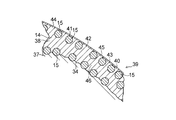
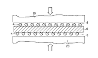
図1は、本発明の実施の形態の一例で製造された球帯状シール体の縦断面図、
図2は、図1に示す球帯状シール体の一部拡大説明図、
図3は、本発明の球帯状シール体の製造工程における補強材の形成方法の説明図、
図4は、本発明の球帯状シール体の製造工程における耐熱材の斜視図、
図5は、補強材の金網の網目を示す平面図、
図6は、本発明の球帯状シール体の製造工程における重合体の斜視図、
図7は、本発明の球帯状シール体の製造工程における筒状母材の平面図、
図8は、図7に示す筒状母材の縦断面図、
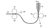
図9は、本発明の球帯状シール体の製造工程における複合シート材の製造工程の説明図、
図10は、図9に示す製造工程における複数個の環状凹溝を有するローラの正面図、
図11は、図9に示す製造工程における円筒状編組金網からなる補強材内に耐熱材を挿入した状態を示す説明図、
図12は、図9に示す製造工程における補強材内に挿入した耐熱材を複数個の環状凹溝を有するローラと円筒ローラとの間に位置させた状態を示す説明図、
図13は、図9に示す製造工程における補強材内に挿入した耐熱材を複数個の環状凹溝を有するローラと円筒ローラとで加圧している状態を示す説明図、
図14は、図9に示す製造工程における補強材内に挿入した耐熱材を複数個の環状凹溝を有するローラと円筒ローラとで加圧したあとの状態を示す説明図、
図15は、図9に示す製造工程における補強材内に挿入した耐熱材を複数個の環状凹溝を有するローラと円筒ローラとで加圧したのち、一対の円筒ローラで加圧している状態を示す説明図、
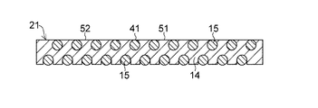
図16は、複合シート材を示す説明図、
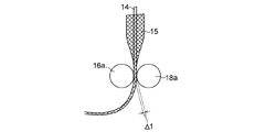
図17は、本発明の球帯状シール体の製造工程における複合シート材の他の製造工程の説明図、
図18は、図17に示す製造工程における円筒状編組金網からなる補強材内に耐熱材を挿入した状態を示す説明図、
図19は、図17に示す製造工程における補強材内に挿入した耐熱材を一対の円筒ローラ間に位置させた状態を示す説明図、
図20は、複合シート材を示す説明図、
図21は、本発明の球帯状シール体の製造工程における複合シート材の他の製造工程の説明図、
図22は、図21に示す製造工程における補強材内に挿入した耐熱材を一対のローラで加圧する状態を示す説明図、
図23は、複合シート材の一方の表面に露出した補強材の露出面積割合を示す画像、
図24は、複合シート材の一方の表面に露出した補強材の露出面積割合を示す画像、
図25は、従来技術の製造方法で作製した複合シート材の一方の表面に露出した補強材の露出面積割合を示す画像、
図26は、従来技術の複合シート材の製造工程を示す説明図、
図27は、従来技術の複合シート材の製造工程を示す説明図、
図28は、従来技術の複合シート材の製造工程を示す説明図、
図29は、従来技術の複合シート材の製造工程を示す説明図、
図30は、本発明の球帯状シール体の製造工程における外層形成部材を示す説明図、
図31は、本発明の球帯状シール体の製造工程における予備円筒成形体の平面図、
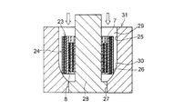
図32は、本発明の球帯状シール体の製造工程における金型中に予備円筒成形体を挿入した状態を示す縦断面図、
図33は、本発明の球帯状シール体を組込んだ排気管球面継手の縦断面図、
図34は、エンジンの排気系の説明図、
図35は、従来の球帯状シール体の説明図、そして、
図36は、従来の球帯状シール体の説明図である。FIG. 1 is a longitudinal sectional view of a ball-shaped seal body manufactured in an example of an embodiment of the present invention,
FIG. 2 is a partially enlarged explanatory view of the ball-shaped seal body shown in FIG.
FIG. 3 is an explanatory view of a method for forming a reinforcing material in the manufacturing process of the ball-shaped seal body of the present invention,
FIG. 4 is a perspective view of the heat-resistant material in the manufacturing process of the ball-shaped seal body of the present invention,
FIG. 5 is a plan view showing a wire mesh of a reinforcing material,
FIG. 6 is a perspective view of a polymer in the production process of the spherical belt-shaped sealing body of the present invention,
FIG. 7 is a plan view of a cylindrical base material in the manufacturing process of the ball-shaped seal body of the present invention,
FIG. 8 is a longitudinal sectional view of the cylindrical base material shown in FIG.
FIG. 9 is an explanatory diagram of the manufacturing process of the composite sheet material in the manufacturing process of the ball-shaped seal body of the present invention,
FIG. 10 is a front view of a roller having a plurality of annular grooves in the manufacturing process shown in FIG.
FIG. 11 is an explanatory view showing a state in which a heat-resistant material is inserted into a reinforcing material made of a cylindrical braided wire mesh in the manufacturing process shown in FIG.
FIG. 12 is an explanatory view showing a state in which the heat-resistant material inserted into the reinforcing material in the manufacturing process shown in FIG. 9 is positioned between a roller having a plurality of annular grooves and a cylindrical roller.
FIG. 13 is an explanatory view showing a state in which the heat-resistant material inserted into the reinforcing material in the manufacturing process shown in FIG. 9 is pressed by a roller having a plurality of annular grooves and a cylindrical roller.
FIG. 14 is an explanatory view showing a state after the heat-resistant material inserted in the reinforcing material in the manufacturing process shown in FIG. 9 is pressed by a roller having a plurality of annular grooves and a cylindrical roller;
FIG. 15 shows a state in which the heat-resistant material inserted into the reinforcing material in the manufacturing process shown in FIG. 9 is pressed with a pair of cylindrical rollers after being pressed with a roller having a plurality of annular grooves and a cylindrical roller. Explanatory diagram showing,
FIG. 16 is an explanatory view showing a composite sheet material;
FIG. 17 is an explanatory diagram of another manufacturing process of the composite sheet material in the manufacturing process of the ball-shaped seal body of the present invention,
18 is an explanatory view showing a state in which a heat-resistant material is inserted into a reinforcing material made of a cylindrical braided wire mesh in the manufacturing process shown in FIG.
19 is an explanatory view showing a state in which the heat-resistant material inserted in the reinforcing material in the manufacturing process shown in FIG. 17 is positioned between a pair of cylindrical rollers.
FIG. 20 is an explanatory view showing a composite sheet material,
FIG. 21 is an explanatory diagram of another manufacturing process of the composite sheet material in the manufacturing process of the spherical belt-shaped sealing body of the present invention,
22 is an explanatory view showing a state in which the heat-resistant material inserted into the reinforcing material in the manufacturing process shown in FIG. 21 is pressed with a pair of rollers.
FIG. 23 is an image showing the exposed area ratio of the reinforcing material exposed on one surface of the composite sheet material;
FIG. 24 is an image showing the exposed area ratio of the reinforcing material exposed on one surface of the composite sheet material;
FIG. 25 is an image showing the exposed area ratio of the reinforcing material exposed on one surface of the composite sheet material produced by the manufacturing method of the prior art,
FIG. 26 is an explanatory view showing a manufacturing process of a conventional composite sheet material,
FIG. 27 is an explanatory view showing a manufacturing process of a conventional composite sheet material,
FIG. 28 is an explanatory view showing a manufacturing process of a conventional composite sheet material,
FIG. 29 is an explanatory view showing a manufacturing process of a conventional composite sheet material,
FIG. 30 is an explanatory view showing an outer layer forming member in the manufacturing process of the ball-shaped seal body of the present invention,
FIG. 31 is a plan view of a pre-cylindrical molded body in the manufacturing process of the ball-shaped seal body of the present invention,
FIG. 32 is a longitudinal sectional view showing a state in which the preliminary cylindrical molded body is inserted into the mold in the manufacturing process of the spherical belt-shaped sealing body of the present invention,
FIG. 33 is a longitudinal sectional view of a spherical joint of an exhaust pipe incorporating the ball-shaped seal body of the present invention,
FIG. 34 is an explanatory diagram of the exhaust system of the engine.
FIG. 35 is an explanatory view of a conventional spherical belt-like seal body, and
FIG. 36 is an explanatory view of a conventional spherical belt-like seal body.
本発明の球帯状シール体における構成材料及び球帯状シール体の製造方法について説明する。 The constituent material in the spherical belt-shaped sealing body of the present invention and the manufacturing method of the spherical belt-shaped sealing body will be described.
<耐熱材Iについて>
濃度98%の濃硫酸を撹拌しながら、酸化剤として過酸化水素の60%水溶液を加え、これを反応液とする。この反応液を冷却して10℃の温度に保持し、該反応液に粒度30〜80メッシュの鱗片状天然黒鉛粉末を添加して30分間反応を行う。反応後、吸引濾過して酸処理黒鉛粉末を分離し、該酸処理黒鉛粉末を水で10分間撹拌して吸引濾過するという洗浄作業を2回繰り返し、酸処理黒鉛粉末から硫酸分を充分除去する。ついで、硫酸分を充分除去した酸処理黒鉛粉末を110℃の温度に保持した乾燥炉で3時間乾燥し、これを酸処理黒鉛粉末とする。<About heat-resistant material I>
While stirring concentrated sulfuric acid having a concentration of 98%, a 60% aqueous solution of hydrogen peroxide is added as an oxidizing agent to make a reaction solution. The reaction solution is cooled and maintained at a temperature of 10 ° C., and scale-like natural graphite powder having a particle size of 30 to 80 mesh is added to the reaction solution and reacted for 30 minutes. After the reaction, the acid-treated graphite powder is separated by suction filtration, and the washing operation of stirring the acid-treated graphite powder with water for 10 minutes and suction-filtering is repeated twice to sufficiently remove the sulfuric acid content from the acid-treated graphite powder. . Next, the acid-treated graphite powder from which sulfuric acid has been sufficiently removed is dried in a drying furnace maintained at a temperature of 110 ° C. for 3 hours to obtain an acid-treated graphite powder.
上記酸処理黒鉛粉末を、950〜1200℃の温度で1〜10秒間加熱(膨張)処理して分解ガスを発生せしめ、そのガス圧により黒鉛層間を拡張して膨張させた膨張黒鉛粒子(膨張倍率240〜300倍)を形成する。この膨張黒鉛粒子を所望のロール隙間に調整した双ローラ装置に供給してロール成形し、所望の厚さの膨張黒鉛シートを作製し、この膨張黒鉛シートを耐熱材Iとする。 The above-mentioned acid-treated graphite powder is heated (expanded) at a temperature of 950 to 1200 ° C. for 1 to 10 seconds to generate decomposition gas, and expanded between graphite layers by the gas pressure (expansion magnification). 240 to 300 times). The expanded graphite particles are supplied to a double roller apparatus adjusted to a desired roll gap and roll-molded to produce an expanded graphite sheet having a desired thickness. This expanded graphite sheet is used as a heat resistant material I.
<耐熱材II及びIIIについて>
上記酸処理黒鉛粉末を撹拌しながら、該酸処理黒鉛粉末にリン酸として濃度84%のオルトリン酸水溶液及びリン酸塩として濃度50%の第一リン酸アルミニウム水溶液のうちの少なくとも一方をメタノールで希釈した溶液を噴霧状に配合し、均一に撹拌して湿潤性を有する混合物を作製する。この湿潤性を有する混合物を、120℃の温度に保持した乾燥炉で2時間乾燥する。ついで、これを950〜1200℃の温度で1〜10秒間加熱(膨張)処理して分解ガスを発生せしめ、そのガス圧により黒鉛層間を拡張して膨張させた膨張黒鉛粒子(膨張倍率240〜300倍)を形成する。この膨張処理工程において、成分中のオルトリン酸は脱水反応を生じて五酸化リンを生成し、第一リン酸アルミニウムは構造式中の水が脱離する。この膨張黒鉛粒子を所望のロール隙間に調整した双ローラ装置に供給してロール成形し、所望の厚さの膨張黒鉛シートを作製し、この膨張黒鉛シートを耐熱材II及びIIIとする。<About heat-resistant materials II and III>
While stirring the acid-treated graphite powder, at least one of an aqueous solution of orthophosphoric acid having a concentration of 84% as phosphoric acid and an aqueous solution of primary aluminum phosphate having a concentration of 50% as phosphate is diluted with methanol. The resulting solution is blended in the form of a spray and stirred uniformly to produce a wettable mixture. The wettable mixture is dried for 2 hours in a drying oven maintained at a temperature of 120 ° C. Subsequently, this was heated (expanded) at a temperature of 950 to 1200 ° C. for 1 to 10 seconds to generate decomposition gas, and expanded graphite particles (expansion magnification: 240 to 300) expanded by expanding the graphite layer by the gas pressure. Times). In this expansion treatment step, orthophosphoric acid in the component causes a dehydration reaction to produce phosphorus pentoxide, and water in the structural formula is eliminated from the primary aluminum phosphate. The expanded graphite particles are supplied to a double-roller apparatus adjusted to a desired roll gap and roll-molded to produce an expanded graphite sheet having a desired thickness. The expanded graphite sheets are designated as heat-resistant materials II and III.
このようにして作製された耐熱材IIには、五酸化リン0.05〜5.0重量%若しくは第一リン酸アルミニウム1〜16重量%が含有されており、耐熱材IIIには、五酸化リン0.05〜5.00重量%と第一リン酸アルミニウム1〜16重量%とが含有されている。このリン酸及びリン酸塩のうちの少なくとも一つを含有した膨張黒鉛は、膨張黒鉛自体の耐熱性が向上されると共に酸化抑制作用が付与されるため、例えば500℃ないし500℃を超える高温領域での使用を可能とする。ここで、リン酸塩としては、オルトリン酸のほかにメタリン酸、ポリリン酸、ポリメタリン酸などを使用することができ、またリン酸塩としては、第一リン酸アルミニウムのほかに第一リン酸リチウム、第二リン酸リチウム、第一リン酸カルシウム、第二リン酸カルシウム、第二リン酸アルミニウムなどを使用することができる。 The heat-resistant material II thus produced contains 0.05 to 5.0% by weight of phosphorus pentoxide or 1 to 16% by weight of primary aluminum phosphate, and the heat-resistant material III contains pentoxide. It contains 0.05 to 5.00% by weight of phosphorus and 1 to 16% by weight of primary aluminum phosphate. The expanded graphite containing at least one of the phosphoric acid and the phosphate is improved in heat resistance of the expanded graphite itself and imparted with an oxidation inhibiting action. For example, a high temperature region exceeding 500 ° C. to 500 ° C. It can be used in Here, as the phosphate, metaphosphoric acid, polyphosphoric acid, polymetaphosphoric acid and the like can be used in addition to orthophosphoric acid, and as the phosphate, in addition to primary aluminum phosphate, primary lithium phosphate Dibasic lithium phosphate, primary calcium phosphate, secondary calcium phosphate, secondary aluminum phosphate, and the like can be used.
上記耐熱材I、II及びIIIにおいて、球帯状基体用に使用される耐熱材I、II及びIIIは、球帯状シール体の製造時において密度が1.0〜1.5Mg/m3、好ましくは1.0〜1.2Mg/m3の耐熱材が使用されて好適である。また、外層用に使用される耐熱材I、II及びIIIは、球帯状シール体の製造時においては上記球帯状基体用に使用される耐熱I、II及びIIIの密度の0.3〜0.6倍の密度、すなわち0.3〜0.9Mg/m3、好ましくは0.3〜0.6Mg/m3の密度を有する耐熱材が使用されて好適である。In the heat-resistant materials I, II and III, the heat-resistant materials I, II and III used for the spherical belt-shaped substrate have a density of 1.0 to 1.5 Mg / m 3 , preferably at the time of producing the spherical belt-shaped sealing body. A heat-resistant material of 1.0 to 1.2 Mg / m 3 is preferably used. Further, the heat-resistant materials I, II, and III used for the outer layer are 0.3 to 0. 0 of the density of the heat-resistant materials I, II, and III used for the above-mentioned spherical belt-shaped substrate when the spherical belt-shaped sealing body is manufactured. A heat-resistant material having a density of 6 times, that is, a density of 0.3 to 0.9 Mg / m 3 , preferably 0.3 to 0.6 Mg / m 3 is preferably used.
<補強材について>
補強材は、鉄系としてオーステナイト系のSUS304、SUS310S、SUS316、フェライト系のSUS430などのステンレス鋼線若しくは鉄線(JISG3532)若しくは亜鉛メッキ鉄線(JISG3547)又は銅系として銅−ニッケル合金(白銅)線、銅−ニッケル−亜鉛合金(洋白)線、黄銅線、ベリリウム銅線からなる金属細線を一本又は二本以上を使用して織ったり、編んだりして形成される織組金網又は編組金網が使用される。<About reinforcing material>
The reinforcing material is austenitic SUS304, SUS310S, SUS316, ferritic SUS430, etc., stainless steel wire or iron wire (JISG3532) or galvanized iron wire (JISG3547) or copper-based copper-nickel alloy (white copper) wire, A woven wire mesh or a braided wire mesh formed by weaving or knitting one or more fine metal wires made of copper-nickel-zinc alloy (white) wire, brass wire, beryllium copper wire used.
金網を形成する金属細線において、その線径は0.15〜0.32mmの範囲の金属細線、具体的には0.15、0.175.0.28及び0.32mmの金属細線が使用されて好適である。球帯状基体用の補強材としての金網は、線径が上記範囲の上限側、例えば0.28〜0.32mmの線径を有する金属細線が好適に使用され、該線径の金属細線で形成された織組金網又は編組金網の網目の目幅は、編組金網を示す図5において、縦4〜6mm、横3〜5mm程度のものが使用されて好適である。また外層用の補強材としての金網は、線径が上記球帯状基体用の補強材としての金網を形成する金属細線の線径と同径の0.28〜0.32mmの金属細線からなる織組金網若しくは編組金網又は線径が上記範囲の下限側、例えば0.15〜0.175mmの線径を有する金属細線が好適に使用され、該線径の金属細線で形成された織組金網又は編組金網の網目の目幅は、編組金網を示す図5において、縦2.5〜3.5mm、横1.5〜2.5mmのものが使用されて好適である。 In the fine metal wire forming the wire mesh, the fine wire diameter is in the range of 0.15 to 0.32 mm, specifically 0.15, 0.175.0.28 and 0.32 mm. It is preferable. For the wire mesh as a reinforcing material for the spherical belt-shaped substrate, a metal fine wire having a wire diameter of the upper limit side of the above range, for example, a wire diameter of 0.28 to 0.32 mm, is preferably used, and is formed by a metal fine wire having the wire diameter. The mesh width of the woven braided or woven braided mesh is preferably about 4 to 6 mm in length and 3 to 5 mm in width in FIG. 5 showing the braided wire mesh. Further, the wire mesh as the reinforcing material for the outer layer is a woven wire composed of a thin metal wire having a wire diameter of 0.28 to 0.32 mm which is the same diameter as the wire diameter of the fine metal wire forming the reinforcing wire for the spherical belt-like substrate. A braided wire mesh or a braided wire mesh, or a metal wire having a wire diameter of the lower limit of the above range, for example, 0.15 to 0.175 mm, is preferably used. The mesh width of the braided wire mesh is preferably 2.5 to 3.5 mm in length and 1.5 to 2.5 mm in width in FIG. 5 showing the braided wire mesh.
<潤滑組成物について>
被覆層(すべり層)を形成する潤滑組成物は、(1)四ふっ化エチレン樹脂(以下「PTFE」と略称する。)粉末からなる潤滑組成物を固形分として含む水性ディスパージョン、(2)分散媒としての酸を含有する水にアルミナ水和物粒子が分散した水素イオン濃度が2〜3を呈するアルミナゾルに六方晶窒化硼素粉末及び酸化硼素粉末を分散含有した水性ディスパージョンであって、六方晶窒化硼素70〜85重量%、酸化硼素0.1〜10重量%及びアルミナ水和物5〜20重量%からなる潤滑組成物を固形分として含む水性ディスパージョン、(3)上記六方晶窒化硼素70〜85重量%、酸化硼素0.1〜10重量%及びアルミナ水和物5〜20重量%からなる潤滑組成物成分に、該潤滑組成物成分100重量部に対し300重量部以下又は200重量部以下、好ましくは50〜200重量部又は50〜150重量部のPTFEを分散含有した潤滑組成物を固形分として含む水性ディスパージョンの形態で適用される。
<About lubricating composition>
The lubricating composition for forming the coating layer (sliding layer) is (1) an aqueous dispersion containing, as a solid content, a lubricating composition comprising a tetrafluoroethylene resin (hereinafter abbreviated as “PTFE”) powder. An aqueous dispersion in which hexagonal boron nitride powder and boron oxide powder are dispersed and contained in an alumina sol having a hydrogen ion concentration of 2 to 3 in which alumina hydrate particles are dispersed in water containing an acid as a dispersion medium. An aqueous dispersion containing, as a solid content, a lubricating composition comprising 70 to 85% by weight of crystalline boron nitride, 0.1 to 10% by weight of boron oxide and 5 to 20% by weight of alumina hydrate, (3) the hexagonal boron nitride 70-85 wt%, the lubricating composition component comprising 0.1 to 10% by weight boron oxide, and 5 to 20 wt% alumina hydrate, 300 weight relative to the
上記潤滑組成物(2)において、六方晶窒化硼素は、とくに高温領域において優れた潤滑性を発揮するものであり、主成分として70〜85重量%を占める。成分中の酸化硼素は、それ自体潤滑性を示すものではないが、主成分をなす六方晶窒化硼素に含有されることにより、該六方晶窒化硼素の具有する潤滑性を引出し、とくに高温領域での摩擦の低下に寄与する。そして、その配合量は好ましくは0.1〜10重量%、より好ましくは3〜5重量%である。また、成分中のアルミナ水和物はそれ自体何らの潤滑性を示すものではが、上記六方晶窒化硼素及び酸化硼素に配合されることにより、潤滑組成物の耐熱材表面への被着性を改善し、強固な被覆層の形成に効果を発揮すると共に六方晶窒化硼素の板状結晶の層間の滑りを助長して六方晶窒化硼素の潤滑性を引出す役割を発揮する。そして、アルミナ水和物は、好ましくは5〜20重量%、より好ましくは7〜15重量%である。アルミナ水和物の含有量5重量%未満では、上記した潤滑組成物の被着性の改善に効果がなく、20重量%を超えて含有すると製造時における水性ディスパージョンが粘稠になりすぎて、ローラ塗り、刷毛塗り等の被着操作を悪化させる。 In the lubricating composition (2), hexagonal boron nitride exhibits excellent lubricity particularly in a high temperature region, and occupies 70 to 85% by weight as a main component. The boron oxide in the component itself does not exhibit lubricity, but by being contained in the hexagonal boron nitride which is the main component, it brings out the lubricity of the hexagonal boron nitride, particularly in the high temperature range. This contributes to a reduction in friction. And the compounding quantity becomes like this. Preferably it is 0.1 to 10 weight%, More preferably, it is 3 to 5 weight%. In addition, the alumina hydrate in the component itself does not exhibit any lubricity, but by blending with the above hexagonal boron nitride and boron oxide, the adherence of the lubricating composition to the surface of the heat-resistant material is improved. This improves the effect of forming a strong coating layer and promotes the slippage between layers of hexagonal boron nitride plate crystals to exert the lubricity of hexagonal boron nitride. And alumina hydrate becomes like this. Preferably it is 5 to 20 weight%, More preferably, it is 7 to 15 weight%. If the content of alumina hydrate is less than 5% by weight, there is no effect in improving the adherence of the lubricating composition described above, and if it exceeds 20% by weight, the aqueous dispersion at the time of production becomes too viscous. Deteriorating deposition operations such as roller coating and brush coating.
また、潤滑組成物(3)において、六方晶窒化硼素70〜85重量%、酸化硼素0.1〜10重量%及びアルミナ水和物5〜20重量%からなる潤滑組成物に含有されるPTFEはそれ自体低摩擦性を有するものであり、該潤滑組成物に含有されることにより、該潤滑組成物の低摩擦性を向上させて該潤滑組成物からなる被覆層(すべり層)に低摩擦性を改善し、相手材との摩擦摺動において、スティックスリップ(付着−すべり)現象を生じることなく、当該スティツクスリップ現象に起因する摩擦異常音の発生を極力回避し得る。また、該潤滑組成物に圧縮成形時の展延性を高める作用をなし、結果として薄い被覆層(すべり層)の形成を可能とする。 Further, in the lubricating composition (3), PTFE contained in the lubricating composition comprising 70 to 85% by weight of hexagonal boron nitride, 0.1 to 10% by weight of boron oxide, and 5 to 20% by weight of alumina hydrate is: It itself has a low friction property, and when contained in the lubricating composition, the low friction property of the lubricating composition is improved and the coating layer (sliding layer) made of the lubricating composition has a low friction property. Thus, the occurrence of abnormal frictional noise due to the stick-slip phenomenon can be avoided as much as possible without causing the stick-slip (adhesion-slip) phenomenon in the frictional sliding with the counterpart material. In addition, the lubricating composition has an effect of enhancing the spreadability at the time of compression molding, and as a result, a thin coating layer (slip layer) can be formed.
上記アルミナゾルにおいて、分散媒としての水に含有された酸は、アルミナゾルを安定化させる解膠剤として作用するものである。そして、酸としては、塩酸、硝酸、硫酸、アミド硫酸等の無機酸が好ましい例として挙げられるが、とくに硝酸が好ましい。そして、アルミナゾルは、水素イオン濃度(pH)が2〜3を呈するものが推奨される。水素イオン濃度が2未満では、アルミナゾル自体が不安定となり、また水素イオン濃度が3を超えるとアルミナゾルの粘度が高くなり、凝集しやすく、不安定となる。 In the alumina sol, the acid contained in water as a dispersion medium acts as a peptizer that stabilizes the alumina sol. Examples of the acid include inorganic acids such as hydrochloric acid, nitric acid, sulfuric acid, and amidosulfuric acid. Nitric acid is particularly preferable. Alumina sol having a hydrogen ion concentration (pH) of 2 to 3 is recommended. When the hydrogen ion concentration is less than 2, the alumina sol itself becomes unstable, and when the hydrogen ion concentration exceeds 3, the viscosity of the alumina sol becomes high and is easily aggregated and becomes unstable.
アルミナゾル中のアルミナ水和物は、組成式Al2O3・nH2O(組成式中、0<n<3)で表される化合物である。該組成式において、nは、通常、0(零)を超えて3未満の数、好ましくは0.5〜2、さらに好ましくは0.7〜1.5程度である。アルミナ水和物としては、例えばベーマイト(Al2O3・H2O)やダイアスポア(Al2O3・H2O)などのアルミナ一水和物(水酸化酸化アルミニウム)、ギブサイト(Al2O3・3H2O)やバイヤライト(Al2O3・3H2O)などのアルミナ三水和物、擬ベーマイトなどが挙げられる。The alumina hydrate in the alumina sol is a compound represented by the composition formula Al 2 O 3 .nH 2 O (0 <n <3 in the composition formula). In the composition formula, n is usually a number exceeding 0 (zero) and less than 3, preferably about 0.5 to 2, and more preferably about 0.7 to 1.5. The alumina hydrate, for example, boehmite (Al 2 O 3 · H 2 O) and diaspore (Al 2 O 3 · H 2 O) alumina monohydrate such as (aluminum hydroxide oxide), gibbsite (Al 2 O 3 · 3H 2 O) and bayerite (Al 2 O 3 · 3H 2 O) alumina trihydrate, such as, such as pseudo-boehmite and the like.
次に、上記した構成材料からなる球帯状シール体の製造方法について図面に基づき説明する。 Next, a method for manufacturing a spherical belt-shaped seal body made of the above-described constituent materials will be described with reference to the drawings.
(第一工程)図3に示すように、線径0.15〜0.32mm、好ましくは0.28〜0.32mmの金属細線を円筒状に編んで形成した網目の目幅が縦4〜6mm、横3〜5mm程度(図5参照)の円筒状編組金網1をローラ2及び3間に通して所定の幅Dの帯状金網4を作製し、帯状金網4を所定の長さLに切断した球帯状基体用の補強材5を準備する。
(First Step) As shown in FIG. 3, the mesh width formed by knitting a thin metal wire having a wire diameter of 0.15 to 0.32 mm, preferably 0.28 to 0.32 mm, in a cylindrical shape has a vertical width of 4 to 4 mm. A cylindrical
(第二工程)図4に示すように、前記補強材5の幅Dに対して1.10×Dから2.10×Dの幅dを有すると共に、前記補強材5の長さLに対して1.30×Lから2.70×Lの長さlを有するように、密度が1.0〜1.5Mg/m3、好ましくは1.0〜1.2Mg/m3の球帯状基体用の耐熱材6(耐熱材I、II及びIIIのうちの一つからなる)を準備する。(Second Step) As shown in FIG. 4, the reinforcing
(第三工程)後述する球帯状シール体39(図1参照)において、部分凸球面状面34(図2参照)の軸方向の少なくとも一方の端縁側の環状端面である大径側の環状端面35に全体的に耐熱材6が露出するようにすべく、図6に示すように、部分凸球面状面34の大径側の環状端面35となる補強材5の幅方向の一方の端縁7から最大で0.1×Dから0.8×Dだけ耐熱材6が幅方向にはみ出すと共に端縁7からの耐熱材6の幅方向のはみ出し量δ1が部分凸球面状面34の小径側の環状端面36となる補強材5の幅方向の他方の端縁8からのはみ出し量δ2よりも多くなるようにすると共に補強材5の長さ方向の一方の端縁9から最大で0.3×Lから1.7×Lだけ耐熱材6が長さ方向にはみ出すと共に、補強材5の長さ方向の他方の端縁10と当該端縁10に対応する耐熱材6の長さ方向の端縁11とを実質的に一致させ、しかも補強材5と耐熱材6との幅方向及び長さ方向を合致させて当該耐熱材6と補強材5とを互いに重ね合わせた重合体12を得る。
(Third Step) In a spherical belt-like seal body 39 (see FIG. 1) to be described later, a large-diameter annular end surface which is an annular end surface on at least one end edge side in the axial direction of the partially convex spherical surface 34 (see FIG. 2) As shown in FIG. 6, one end edge in the width direction of the reinforcing
(第四工程)重合体12を図7に示すように耐熱材6を内側にしてうず巻き状であって耐熱材6が1回多くなるように捲回して、内周側及び外周側の両方に耐熱材6が露出した筒状母材13を形成する。耐熱材6としては、筒状母材13における耐熱材6の巻き回数が補強材5の巻き回数よりも多くなるように、補強材5の長さLに対して1.30×Lから2.70×Lの長さlを有したものが予め準備される。筒状母材13においては、図8に示すように、耐熱材6は、幅方向の一方の端縁側において補強材5の一方の端縁7から幅方向にδ1だけはみ出しており、また耐熱材6の幅方向の他方の端縁側において補強材5の他方の端縁8から幅方向にδ2だけはみ出している。
(Fourth step) The
(第五工程)密度が0.3〜0.9Mg/m3、好ましくは0.3〜0.6Mg/m3の外層用の耐熱材(耐熱材I、II及びIIIのうちの一つからなる)14を別途準備する。(Fifth step) Heat-resistant material for outer layer having a density of 0.3 to 0.9 Mg / m 3 , preferably 0.3 to 0.6 Mg / m 3 (from one of heat-resistant materials I, II and III) 14) is prepared separately.
(第六工程)
<第一の方法> 線径が0.15〜0.32mm、好ましくは0.15〜0.28mmの金属細線を編み機(図示せず)で連続的に編んで得られる円筒状編組金網(編組金網の網目の目幅は縦2.5〜3.5mm、横1.5〜2.5mm)からなる外層用の補強材15の内部に外層用の耐熱材14を連続的に挿入(図9参照)し、該耐熱材14を挿入した補強材15をその挿入開始端側から平滑な円筒状の外周面を有する円筒ローラ16と軸方向に沿って複数個の環状凹溝17をもった円筒状の外周面を有したローラ18(図9及び図10参照)との間の隙間Δ1に供給して該耐熱材14の厚さ方向に加圧(図9、図11、図12、図13及び図14参照)し、さらに別の平滑な円筒状の外周面を有する一対の円筒ローラ19及び20間の隙間Δ2に供給(図9及び図15参照)して加圧し、外層用の補強材15の金網の網目に外層用の耐熱材14を密に充填すると共に該外層用の耐熱材14中に外層用の補強材15が埋設するように互いに圧着して、外層用の耐熱材14の表面と外層用の補強材15の表面とを面一に形成すると共に耐熱材14の表面と補強材15の表面とが露出した扁平状の複合シート材21(図16参照)を形成し、これを筒状母材13の外周面を一巻きできる程度の長さに切断する。(Sixth process)
<First Method> Cylindrical braided wire mesh (braided) obtained by continuously knitting a thin metal wire having a wire diameter of 0.15 to 0.32 mm, preferably 0.15 to 0.28 mm, with a knitting machine (not shown). The outer layer heat-
円筒ローラ16と軸方向に沿って複数個の環状凹溝17を外周面に有するローラ18との隙間Δ1は、0.35〜0.60mmの範囲に設定されるのが好ましく、また一対のローラ19及び20間の隙間Δ2は、0.45〜0.65mmの範囲に設定されるのが好ましい。
The gap Δ1 between the
<第二の方法> 図17ないし図20に示すように、密度が0.3〜0.9Mg/m3、好ましくは0.3〜0.6Mg/m3の外層用の耐熱材(耐熱材I、II及びIIIのうちの一つからなる)14を別途準備する。線径が0.15〜0.32mm、好ましくは0.15〜0.175mmの金属細線を編み機(図示せず)で連続的に編んで得られる円筒状編組金網(金網の網目の目幅は縦2.5〜3.5mm、横1.5〜2.5mm)からなる外層用の補強材15の内部に外層用の耐熱材14を連続的に挿入(図17参照)し、該耐熱材14を挿入した外層用の補強材15をその挿入開始端側から平滑な円筒状の外周面を有する一対の円筒ローラ16a及び18a間のすきまΔ1に供給し該耐熱材14の厚さ方向に加圧(図18及び図19参照)し、外層用の補強材15の金網の網目に外層用の耐熱材14を密に充填すると共に該外層用の耐熱材14中に外層用の補強材15を埋設するように互いに圧着して、外層用の耐熱材14の表面と外層用の補強材15の表面とを面一に形成すると共に耐熱材14の表面と補強材15の表面とが露出した扁平状の複合シート材21(図20参照)を形成し、これを筒状母材13の外周面を一巻きできる程度の長さに切断する。<Second Method> As shown in FIG. 17 to FIG. 20, a heat-resistant material for outer layer (heat-resistant material) having a density of 0.3 to 0.9 Mg / m 3 , preferably 0.3 to 0.6 Mg / m 3. (Comprising one of I, II and III) 14 is prepared separately. Cylindrical braided wire mesh obtained by continuously knitting a metal wire having a wire diameter of 0.15 to 0.32 mm, preferably 0.15 to 0.175 mm with a knitting machine (not shown). The outer layer heat-
上記一対の円筒ローラ16a及び18a間の隙間Δ1は、0.35〜0.60mmの範囲に設定されるのが好ましい。なお、上記第二の方法においても、前記第一の方法における別の平滑な円筒状の外周面を有する一対の円筒ローラ19及び20間の隙間Δ2に供給(図9及び図15参照)して加圧する工程を入れてもよい。
The gap Δ1 between the pair of
<第三の方法> 図21及び図22に示すように、前記第五工程で得た外層用の耐熱材14と同様、外層用の補強材(帯状金網)15の幅Dよりも小さい幅dを有すると共に密度が0.3〜0.9Mg/m3、好ましくは0.3〜0.6Mg/m3の外層用の耐熱材(耐熱材I、II及びIIIのうちの一つからなる)14を別途準備する。線径が0.15〜0.32mm、好ましくは0.15〜0.175mmの金属細線を編んで形成される円筒状編組金網からなる外層用の補強材15を一対の円筒ローラ2及び3間の隙間に通して帯状金網4(図3参照)を作製し、この帯状金網4を予め筒状母材13の外周面を一巻きできる程度の長さに切断する。該帯状金網4内に外層用の耐熱材14を挿入する(図21参照)と共に一対の円筒ローラ16b及び18b間の隙間Δ1に通して該外層用の耐熱材14の厚さ方向に加圧し、帯状金網4からなる外層用の補強材15の金網の網目に外層用の耐熱材14が埋設するように互いに圧着して、外層用の耐熱材14の表面と外層用の補強材15の表面とを面一に形成すると共に該外層用の耐熱材14の表面と外層用の補強材15の表面とが露出した扁平状の複合シート材21(図22参照)を形成し、これを筒状母材13の外周面を一巻きできる程度の長さに切断する。<Third Method> As shown in FIG. 21 and FIG. 22, the width d smaller than the width D of the outer layer reinforcing material (band metal mesh) 15 as in the outer layer heat-
上記一対の円筒ローラ16b及び18b間の隙間Δ1は、0.35〜0.60mmの範囲の隙間に設定されるのが好ましい。なお、第三の方法においても、前記第一の方法における別の平滑な円筒状の外周面を有する一対の円筒ローラ19及び20間の隙間Δ2に供給して加圧する工程を入れてもよい。
The gap Δ1 between the pair of
<第四の方法(図示せず)> 前記第五工程で得た外層用の耐熱材14と同様、外層用の補強材(帯状金網)15の幅Dと同じ幅を有すると共に密度が0.3〜0.9Mg/m3、好ましくは0.3〜0.6Mg/m3の外層用の耐熱材(耐熱材I、II及びIIIのうちの一つからなる)14を別途準備する。線径が0.15〜0.32mm、好ましくは0.15〜0.175mmの金属細線を織って形成される織組金網として平織金網を用意し、この平織金網からなる外層用の補強材15を所定長さと幅とに切断し、該外層用の補強材15を2枚準備する。2枚の外層用の補強材15の間に前記外層用の耐熱材14を挿入(挟み)すると共に一対の円筒ローラ間の隙間に通して該耐熱材14の厚さ方向に加圧し、平織金網からなる外層用の補強材15の金網の網目に外層用の耐熱材14を密に充填すると共に該外層用の耐熱材14中に外層用の補強材15が埋設するように互いに圧着して、外層用の耐熱材14の表面と外層用の補強材15の表面とを面一に形成すると共に外層用の耐熱材14の表面と外層用の補強材15の表面とが露出した扁平状の複合シート材21を形成し、これを筒状母材13の外周面を一巻きできる程度の長さに切断する。<Fourth Method (not shown)> Similar to the outer layer heat-
上記一対の円筒ローラ間の隙間は、0.35〜0.60mmの範囲の隙間に設定されるのが好ましい。なお、上記第四の方法においても、前記第一の方法における別の平滑な円筒状の外周面を有する一対の円筒ローラ19及び20間の隙間Δ2に供給する工程を入れてもよい。
The gap between the pair of cylindrical rollers is preferably set to a gap in the range of 0.35 to 0.60 mm. In the fourth method, a step of supplying the gap Δ2 between the pair of
上記第一、第二、第三及び第四の方法で得られた扁平状の複合シート材21の一方の表面51において、外層用の耐熱材14の表面52と共に露出する外層用の補強材15の表面41の面積割合は、複合シート材21の一方の表面51の面積の5〜35%であることが好ましく、また、外層用の耐熱材14の表面52と共に露出する外層用の補強材15の表面41をもった扁平状の複合シート材21の一方の表面51の表面粗さは、算術平均粗さRaで5〜30μmであることが好ましい。
On one
複合シート材21において、円筒ローラ16及び外周面に軸方向に沿って複数個の環状凹溝17を有するローラ18によって、更には一対の円筒ローラ19及び20によって(前記第一の方法)又は平滑な円筒状の外周面を有する一対の円筒ローラ16a及び18a、場合によっては更に一対の円筒ローラ19及び20によって(前記第二の方法)又は前記第三及び第四の方法によってそれぞれ加圧された後の外層用の補強材15のスプリングバックは小さいこと、一方、外層用の耐熱材14は、密度が0.3〜0.9Mg/m3(球帯状基体用の耐熱材6の密度の0.3〜0.6倍)の低密度であることから、該耐熱材14の厚さ方向の加圧工程によって、外層用の耐熱材14と外層用の耐熱材15とは、外層用の耐熱材14が外層用の補強材15の金網の網目に隙間なく密に充填されると共に該外層用の耐熱材14中に外層用の補強材15が埋設されるように、互いに圧着される。補強材15の表面41が複合シート材21の一方の表面51の耐熱材14の表面52と共に露出していることにより、最終の球帯状シール体39の外層38の外層中間面42(図1及び図2参照)での補強材15の表面41の占有面積割合は5〜35%となる。In the
また、補強材15の表面41が複合シート材21の一方の表面51の耐熱材14の表面52と共に5〜35%の面積割合で露出した複合シート材21の表面粗さは、算術平均粗さRaで5〜30μmとなっている。
Further, the surface roughness of the
複合シート材21の一方の表面51に露出した外層用の補強材15の表面41の露出面積割合を画像測定した結果と、外層用の補強材15の表面41が露出した複合シート材21の一方の表面51の表面粗さを算術平均粗さRaで測定した結果を説明する。
Results of image measurement of the exposed area ratio of the
線径0.15mmのSUS304の線材を用いて縦3.5mm、横1.5mmの目幅を有する円筒状編組金網と、線径0.28mmのSUS304の線材を用いて縦3.5mm、横1.5mmの目幅を有する円筒状編組金網とを夫々作製し、これら円筒状編組金網からなる外層用の補強材15の内部に、密度0.3Mg/m3、厚さ1.5mmの膨張黒鉛からなる耐熱シート材14を挿入し、円筒ローラ16と外周面に軸方向に沿って複数個の環状凹溝17を有するローラ18との間の隙間Δ1を0.40mmに設定し、また一対の円筒ローラ19及び20間の隙間Δ2を0.45mmに設定して複合シート材21を作製した。これらの複合シート21材について、該複合シート材21の表面51の耐熱材14の表面52と共に露出する補強材15の表面41の面積割合を、キーエンス社製の画像測定カメラCV−3000を用いて画像測定した。また、補強材15の表面41が露出した複合シート材21の一方の表面51の算術平均粗さRaは、該複合シート材21の幅方向及び長さ方向の60箇所の表面粗さを測定し、その平均値で示した。A cylindrical braided wire net having a mesh width of 3.5 mm in length and 1.5 mm in width using a SUS304 wire with a wire diameter of 0.15 mm, and a length of 3.5 mm in width using a SUS304 wire with a wire diameter of 0.28 mm. Cylindrical braided wire meshes having a mesh width of 1.5 mm are respectively produced, and an expansion of a density of 0.3 Mg / m 3 and a thickness of 1.5 mm is provided inside the outer
図23は、線径0.15mmのSUS304の金属細線を用いて作製した縦3.5mm、横1.5mmの目幅を有する円筒状編組金網と密度0.3Mg/m3、厚さ1.5mmの膨張黒鉛からなる耐熱シート材14を用いて作製した複合シート材21の画像測定写真であり、外層用の補強材15の表面41の露出面積割合は、26.528%であった。また、複合シート材21の表面51の算術平均粗さRaは、8.34μmであった。FIG. 23 shows a cylindrical braided wire mesh having a mesh width of 3.5 mm in length and 1.5 mm in width produced using a SUS304 fine metal wire having a wire diameter of 0.15 mm, a density of 0.3 Mg / m 3 , a thickness of 1. It is the image measurement photograph of the
図24は、線径0.28mmのSUS304の金属細線を用いて作製した縦3.5mm、横1.5mmの目幅を有する円筒状編組金網と密度0.3Mg/m3、厚さ1.5mmの膨張黒鉛からなる耐熱シート材14を用いて作製した複合シート材21の画像測定写真であり、外層用の補強材15の表面41の露出面積割合は、23.212%であった。また、複合シート材21の表面51の算術平均粗さRaは、10.82μmであった。FIG. 24 shows a cylindrical braided wire mesh having a mesh width of 3.5 mm in length and 1.5 mm in width produced using a SUS304 metal wire having a wire diameter of 0.28 mm, a density of 0.3 Mg / m 3 , a thickness of 1. It is the image measurement photograph of the
密度が0.3〜0.9Mg/m3で、厚さが1.30〜1.50mmの外層用の耐熱材14を使用し、線径が0.15〜0.28mmの金属細線を用いて作製した外層用の補強材15を使用した場合に、複合シート材21の一方の表面51での補強材15の露出面積割合は、円筒ローラ16と外周面に軸方向に沿って複数個の環状凹溝17を有するローラ18との間の隙間Δ1を0.35〜0.60mmの範囲に、また一対の円筒ローラ19及び20間の隙間Δ2を0.45〜0.65mmの範囲に適宜選定することにより、5〜35%の面積割合の範囲で適宜調整することができる。The outer layer heat-
また、密度が0.3〜0.9Mg/m3で、厚さが1.30〜1.50mmの外層用の耐熱材14を使用し、線径が0.15〜0.175mmの金属細線を用いて作製した外層用の補強材15を使用した場合に、複合シート材21の一方の表面51での補強材15の露出面積割合は、一対の円筒ローラ16a及び18a間の隙間Δ1を0.35〜0.60mmの範囲に適宜選定することにより、5〜35%の面積割合の範囲で適宜調整することができる。Further, a heat
なお、図25は従来技術である前記特許文献3に記載された方法によって作製した複合シート材21aの画像測定写真を示すものであり、この複合シート材21aの製造方法を図26乃至図29によって説明する。すなわち、線径0.28mmのオーステナイト系ステンレス鋼線を使用して網目の目幅が縦4mm、横3mmの円筒状編組金網を作製し、これを一対のローラ間2及び3に通して帯状金網4(図3参照)とし、これを外層用の補強材5とした。外層用の耐熱材6として、五酸化リン0.7重量%、第一リン酸アルミニウム4.0重量%及び膨張黒鉛を含む密度1.12Mg/m3、厚さ0.4mmの耐熱材を使用した。FIG. 25 shows an image measurement photograph of the
上記補強材5と同様の円筒状編組金網を別途作製した後、これをローラ2及び3間に通して作製した帯状金網4を準備し、該帯状金網4内に外層用の耐熱材6を挿入する(図21及び図26参照)と共にこれらを一対の円筒ローラ19及び20間に通して一体化させ(図26、図27及び図28参照)、耐熱材6の表面と補強材5の表面とが露出した偏平状の複合シート材21a作製した(図29参照)。該複合シート材21aの表面51a中において補強材5の表面41aが露出する面積割合は、43.339%であり、複合シート材21aの表面51aの算術平均粗さRaは、71.18μmであった。
A cylindrical braided wire mesh similar to that of the reinforcing
(第七工程)潤滑組成物として、(1)PTFE粉末からなる潤滑組成物を固形分として60重量%含む水性ディスパージョン、(2)分散媒としての酸を含有する水にアルミナ水和物粒子を分散含有した水素イオン濃度(pH)が2〜3を呈するアルミナゾルに六方晶窒化硼素粉末及び酸化硼素粉末を分散含有した水性ディスパージョンであって、六方晶窒化硼素70〜85重量%、酸化硼素1〜10重量%及びアルミナ水和物5〜20重量%からなる潤滑組成物を固形分として30重量%含む水性ディスパージョン、(3)上記六方晶窒化硼素70〜85重量%、酸化硼素1〜10重量%及びアルミナ水和物5〜20重量%からなる潤滑組成物成分に、該潤滑組成物成分100重量部に対し300重量部以下又は200重量部以下、好ましくは50〜200重量部又は50〜150重量部のPTFE粉末を分散含有した潤滑組成物を固形分として含む水性ディスパージョンのいずれかを準備する。
(Seventh Step) As a lubricating composition, (1) an aqueous dispersion containing 60% by weight of a lubricating composition made of PTFE powder as a solid content, and (2) water containing an acid as a dispersion medium, alumina hydrate particles An aqueous dispersion in which hexagonal boron nitride powder and boron oxide powder are dispersed and contained in an alumina sol having a hydrogen ion concentration (pH) of 2 to 3 dispersed therein, the hexagonal boron nitride being 70 to 85% by weight, boron oxide An aqueous dispersion containing 30% by weight as a solid content of a lubricating composition comprising 1 to 10% by weight and
前記第一、第二、第三又は第四の方法で作製した複合シート材21の表面51に、前記(1)の潤滑組成物、すなわちPTFE粉末からなる潤滑組成物を固形分として60重量%分散含有した水性ディスパージョン(PTFE60重量%、水分40重量%)をローラ塗りした後、乾燥して該潤滑組成物からなる被覆層22を形成した外層形成部材23(図30参照)を形成する。
On the
又は、複合シート材21の表面51に、前記(2)の潤滑組成物、すなわち六方晶窒化硼素70〜85重量%、酸化硼素0.1〜10重量%及びアルミナ水和物5〜20重量%からなる潤滑組成物を固形分として30重量%分散含有した水性ディスパージョン(六方晶窒化硼素35〜42.5重量%、酸化硼素0.05〜5重量%、アルミナ水和物2.5〜10重量%、水分70重量%)をローラ塗りした後、乾燥して該潤滑組成物からなる被覆層22を形成した外層形成部材23を形成する。
Or, on the
さらには、複合シート材21の表面51に、前記(3)の潤滑組成物、すなわち六方晶窒化硼素17.5〜56.7重量%、酸化硼素0.025〜6.7重量%、アルミナ水和物1.25〜13.3重量%及びPTFE33.3〜75重量%を含む潤滑組成物を固形分として35〜50%分散含有した水性ディスパージョンをローラ塗りした後、乾燥して該潤滑組成物の被覆層22を形成した外層形成部材23を形成する。
Furthermore, on the
上記の潤滑組成物(2)及び(3)において、アルミナ水和物は、例えばベーマイト(Al2O3・H2O)又はダイアスポア(Al2O3・H2O)などのアルミナ一水和物(水酸化酸化アルミニウム)、ギブサイト(Al2O3・3H2O)やバイヤライト(Al2O3・3H2O)などのアルミナ三水和物、擬ベーマイトなどの少なくとも一つが使用される。In the lubricating compositions (2) and (3), the alumina hydrate is, for example, alumina monohydrate such as boehmite (Al 2 O 3 .H 2 O) or diaspore (Al 2 O 3 .H 2 O). At least one of alumina trihydrate, pseudoboehmite, and the like (aluminum hydroxide oxide), gibbsite (Al 2 O 3 .3H 2 O) and bayerite (Al 2 O 3 .3H 2 O) are used. .
(第八工程)このようにして得た外層形成部材23をその被覆層22を外側にして筒状母材13の外周面に巻付け、予備円筒成形体24を作製する(図31参照)。
(Eighth step) The outer
(第九工程)内面に円筒壁面25と円筒壁面25に連なる部分凸球面状面26と部分凸球面状面26に連なる貫通孔27を備え、貫通孔27に段付きコア28を嵌挿することによって内部に中空円筒部29と該中空円筒部29に連なる球帯状中空部30とが形成された図32に示すような金型31を準備し、該金型31の段付きコア28に予備円筒成形体24を挿入する。
(Ninth Step) A
金型31の中空円筒部29及び球帯状中空部30に配された予備円筒成形体24をコア軸方向に98〜392N/mm2(1〜4トン/cm2)の圧力で圧縮成形し、図1及び図2に示すような、中央部に貫通孔32を有すると共に円筒内面33と部分凸球面状面34と部分凸球面状面34の大径側及び小径側の環状端面35及び36とにより規定された球帯状基体37と、球帯状基体37の部分凸球面状面34に一体に形成された外層38とを備えた球帯状シール体39を作製する。The pre-cylindrical molded
この圧縮成形により、球帯状基体37は、球帯状基体用の耐熱材6と球帯状基体用の補強材5とが互いに圧縮され、互いに絡み合って構造的一体性を有すように構成されており、外層38の表面44は、外層用の耐熱材14の表面43と耐熱材14の表面43と面一となった外層用の補強材15の表面41とからなる外層中間面42に一体に被着形成された潤滑組成物のすべり層40の平滑な面45からなっている。
By this compression molding, the ball-shaped
第四工程において、重合体12を、耐熱シート材6を内側にしてうず巻き状に捲回する代わりに、帯状金網4からなる補強材5を内側にしてうず巻き状に捲回して筒状母材13を形成すると、球帯状基体37の金網からなる補強材5が円筒内面33において露出する球帯状シール体39を作製することができる。この円筒内面33に金網からなる補強材5が露出した球帯状シール体39においては、排気管の外周面に圧入嵌合する際の嵌合力が強くなり、該排気管の外周面に強固に固着される。
In the fourth step, instead of winding the
作製された球帯状シール体39は、円筒内面33、部分凸球面状面34並びに部分凸球面状面34の大径側及び小径側の環状端面35及び36により規定された球帯状基体37と、球帯状基体37の部分凸球面状面34に一体に形成された外層38とを備えており、球帯状基体37は、金網からなる補強材5と、補強材5の金網の網目を充填し、かつ補強材5と混在一体化されていると共に圧縮された膨張黒鉛を含む耐熱材6とを具備しており、外層38は、金網からなると共に圧縮された補強材15及び補強材15の金網の網目を充填し、かつ補強材15に密に圧着されていると共に当該補強材15の表面41と面一であって当該表面41と共に外層中間面42を形成する表面43を有して圧縮された膨張黒鉛からなる耐熱材14を含み、かつ部分凸球面状面34に一体に形成された基層46と、該外層中間面42で基層46に一体に被着形成されている潤滑組成物のすべり層40とを具備しており、該外層38における補強材15と耐熱材14とで形成された基層46の外層中間面42には、該補強材15が5〜35%の面積割合をもって点在していると共に外層中間面42の表面粗さが算術平均粗さRaで5〜30μmに形成されており、外部に露出する外層38の表面44は、すべり層40の平滑な面45からなっている。
The produced spherical belt-shaped sealing
球帯状シール体39は、図33に示す排気管球面継手に組込まれて使用される。すなわち、図33に示す排気管球面継手において、エンジン側に連結された上流側排気管100の外周面には、管端部101を残してフランジ102が立設されており、管端部101には、球帯状シール体39が貫通孔32を規定する円筒内面33において嵌合されており、大径側の環状端面35において球帯状シール体39がフランジ102に当接されて着座せしめられており、上流側排気管100と相対峙して配されていると共にマフラー側に連結された下流側排気管200には、凹球面部201と凹球面部201に連接されたフランジ部202とを一体に備えた径拡大部203が固着されており、凹球面部201の内面204が球帯状シール体39の外層38におけるすべり層40の平滑な面45に摺接されている。
The spherical belt-
図33に示す排気管球面継手において、一端がフランジ102に固定され、他端が径拡大部203のフランジ部202を挿通して配された一対のボルト300とボルト300の膨大頭部及びフランジ部202の間に配された一対のコイルバネ400とにより、下流側排気管200には、常時、上流側排気管100方向にバネ力が付勢されている。そして、排気管球面継手は、上、下流側排気管100、200に生じる相対角変位に対しては、球帯状シール体39の外層38の平滑な面45と下流側排気管200の端部に形成された径拡大部203の凹球面部201の内面204との摺接でこれを許容するように構成されている。
In the exhaust pipe spherical joint shown in FIG. 33, a pair of
次に、本発明を実施例に基づき詳細に説明する。なお、本発明はこれら実施例に何等限定されないのである。 Next, the present invention will be described in detail based on examples. The present invention is not limited to these examples.
実施例1
金属細線として線径0.28mmのオーステナイト系ステンレス鋼線(SUS304)を一本使用して網目の目幅が縦4mm、横5mmの円筒状編組金網を作製し、これを一対のローラ間に通して帯状金網とし、これを球帯状基体用の補強材とした。耐熱材として、密度1.12Mg/m3、厚さ0.4mmの膨張黒鉛シートを使用した。耐熱材をうず巻き状に一周分捲回したのち、耐熱材の内側に球帯状基体用の補強材を重ね合わせ、うず巻き状に捲回して最外周に耐熱材を位置させた筒状母材を作製した。この筒状母材においては、耐熱材の幅方向の両端部はそれぞれ球帯状基体用の補強材の幅方向に突出(はみ出し)している。Example 1
Using one austenitic stainless steel wire (SUS304) with a wire diameter of 0.28 mm as a thin metal wire, a cylindrical braided wire mesh with a mesh width of 4 mm and a width of 5 mm is produced, and this is passed between a pair of rollers. A belt-like wire mesh was used as a reinforcing material for a spherical belt-like substrate. As a heat-resistant material, an expanded graphite sheet having a density of 1.12 Mg / m 3 and a thickness of 0.4 mm was used. After winding the heat-resistant material in a spiral shape, stack the reinforcing material for the ball belt-shaped substrate on the inside of the heat-resistant material and wind it in a spiral shape to produce a cylindrical base material with the heat-resistant material positioned on the outermost circumference did. In this cylindrical base material, both end portions in the width direction of the heat-resistant material protrude (extrude) in the width direction of the reinforcing material for the ball-shaped base.
外層用の耐熱材として、密度0.3Mg/m3、厚さ1.35mmの膨張黒鉛シートを使用した。外層用の補強材として、前記球帯状基体用の補強材と同様の線径0.28mmのオーステナイト系ステンレス鋼線(SUS304)を使用して網目の目幅が縦3.5mm、横2.5mmの円筒状編組金網を連続的に編むと共に該円筒状編組金網の内面に外層用の耐熱材を連続的に挿入し、該耐熱材の挿入開始端から該耐熱材を挿入した補強材を、円筒ローラと外周面に軸方向に沿って複数個の環状凹溝を有するローラとの隙間(隙間Δ1は0.50mmとした。)に供給して該耐熱材の厚さ方向に加圧し、さらに別の一対の円筒ローラ間の隙間(隙間Δ2は0.45mmとした。)に供給し、加圧して補強材の金網の網目に外層用の耐熱材を密に充填すると共に該外層用の耐熱材中に補強材が埋設するように互いに圧着して、外層用の耐熱材の表面と補強材の表面とを面一に形成すると共に該補強材の表面と外層用の耐熱材の表面とが点在して露出した扁平状の複合シート材を作製した。この複合シート材において、補強材の表面が複合シート材の一方の表面で耐熱材の表面と共に露出する面積割合は、26.4%であり、その表面の算術平均粗さRaは19.3μmであった。As the heat-resistant material for the outer layer, an expanded graphite sheet having a density of 0.3 Mg / m 3 and a thickness of 1.35 mm was used. As the reinforcing material for the outer layer, an austenitic stainless steel wire (SUS304) having a wire diameter of 0.28 mm, which is the same as the reinforcing material for the spherical band substrate, is used, and the mesh width is 3.5 mm in length and 2.5 mm in width. A cylindrical braided wire mesh is continuously knitted, and a heat-resistant material for the outer layer is continuously inserted into the inner surface of the cylindrical braided wire mesh, and a reinforcing material into which the heat-resistant material is inserted from the insertion start end of the heat-resistant material is Supply to a gap (gap Δ1 is 0.50 mm) between the roller and a roller having a plurality of annular grooves along the outer peripheral surface along the axial direction, and pressurize in the thickness direction of the heat-resistant material. Is supplied to a gap between the pair of cylindrical rollers (gap Δ2 is set to 0.45 mm), and the outer layer heat-resistant material is densely filled in the mesh of the reinforcing material wire mesh by pressurization. Crimp each other so that the reinforcing material is buried inside, and heat resistant material for the outer layer A flat composite sheet material was produced in which the surface and the surface of the reinforcing material were formed flush with each other, and the surface of the reinforcing material and the surface of the heat-resistant material for the outer layer were scattered. In this composite sheet material, the area ratio at which the surface of the reinforcing material is exposed together with the surface of the heat-resistant material on one surface of the composite sheet material is 26.4%, and the arithmetic average roughness Ra of the surface is 19.3 μm. there were.
潤滑組成物として、解膠剤として作用する硝酸を含有した分散媒としての水にアルミナ水和物としてベーマイト(アルミナ一水和物:Al2O3・H2O)を分散含有した水素イオン濃度(pH)が2を呈するアルミナゾルを準備し、このアルミナゾルに六方晶窒化硼素粉末及び酸化硼素粉末を分散含有した水性ディスパージョンであって、六方晶窒化硼素83重量%と酸化硼素4重量%及びベーマイト13重量%とを含む潤滑組成物を固形分として30重量%分散含有した水性ディスパージョンA(六方晶窒化硼素24.9重量%、酸化硼素1.2重量%、ベーマイト3.9重量%並びに水及び硝酸70重量%)を作製した。Hydrogen ion concentration containing boehmite (alumina monohydrate: Al 2 O 3 .H 2 O) dispersed in water as a dispersion medium containing nitric acid acting as a peptizer as a lubricating composition An aqueous dispersion in which an alumina sol having a (pH) of 2 is prepared, and hexagonal boron nitride powder and boron oxide powder are dispersed and contained in the alumina sol, comprising 83% by weight of hexagonal boron nitride, 4% by weight of boron oxide, and boehmite Aqueous dispersion A (a hexagonal boron nitride 24.9% by weight, boron oxide 1.2% by weight, boehmite 3.9% by weight, and water containing a lubricating composition containing 13% by weight of a dispersion containing 30% by weight as a solid content) And 70% by weight of nitric acid).
上記水性ディスパージョンAを前記複合シート材の前記環状凹溝を有するローラによって加圧された側の表面にローラ塗りし、乾燥して該複合シート材の表面に潤滑組成物からなる固体潤滑剤の被覆層(六方晶窒化硼素83重量%、酸化硼素4重量%及びベーマイト13重量%)を形成した外層形成部材を作製した。 The aqueous dispersion A is roller-coated on the surface of the composite sheet material that has been pressed by the roller having the annular groove, and dried to form a solid lubricant composed of a lubricating composition on the surface of the composite sheet material. An outer layer forming member on which a coating layer (83% by weight of hexagonal boron nitride, 4% by weight of boron oxide and 13% by weight of boehmite) was formed was produced.
前記筒状母材の外周面に前記外層形成部材をその被覆層を外側にして捲回し、予備円筒成形体を作製した。この予備円筒成形体を図32に示す金型の段付きコアに挿入し、該予備円筒成形体を金型の中空部に位置させた。 The outer layer forming member was wound around the outer peripheral surface of the cylindrical base material with the coating layer facing outward to prepare a preliminary cylindrical molded body. This preliminary cylindrical molded body was inserted into the stepped core of the mold shown in FIG. 32, and the preliminary cylindrical molded body was positioned in the hollow portion of the mold.
金型の中空部に配した予備円筒成形体をコア軸方向に294N/mm2(3トン/cm2)の圧力で圧縮成形し、中央部に貫通孔を有すると共に円筒内面と部分凸球面状面と部分凸球面状面の大径側及び小径側の環状端面とにより規定された球帯状基体と、球帯状基体の部分凸球面状面に一体的に形成された外層とを備えた球帯状シール体を得た。A pre-cylindrical molded body placed in the hollow part of the mold is compression-molded with a pressure of 294 N / mm 2 (3 ton / cm 2 ) in the core axial direction, and has a through-hole in the central part and a cylindrical inner surface and a partially convex spherical shape. A spherical band comprising a spherical band-shaped substrate defined by the surface and annular end surfaces on the large-diameter side and small-diameter side of the partially convex spherical surface, and an outer layer integrally formed on the partially convex spherical surface of the spherical band-shaped substrate A seal body was obtained.
この圧縮成形により、球帯状基体は、球帯状基体用の耐熱材と金網からなる球帯状基体用の補強材とが圧縮され、互いに絡み合って構造的一体性を有するように構成され、圧縮された金網からなる球帯状基体用の補強材と、この補強材の網目を充填し、かつこの補強材と混在一体化されて圧縮された膨張黒鉛からなる球帯状基体用の耐熱材とを有しており、外層の表面は、外層用の耐熱材の表面と該耐熱材の表面と面一となった外層用の補強材の表面とからなる外層中間面で基層に一体に被着形成された六方晶窒化硼素83重量%、酸化硼素4重量%及びベーマイト13重量%を含む潤滑組成物の被覆層からなるすべり層の平滑な面に形成されている。 By this compression molding, the spherical belt-shaped substrate is configured such that the heat-resistant material for the spherical belt-shaped substrate and the reinforcing material for the spherical belt-shaped substrate made of a wire mesh are compressed and entangled with each other to have structural integrity. A reinforcing material for a spherical belt-shaped substrate made of a wire mesh, and a heat-resistant material for a spherical belt-shaped substrate made of expanded graphite that is packed together with the reinforcing material and compressed by being mixed and integrated with the reinforcing material. The outer layer has a hexagonal surface integrally formed on the base layer on the outer layer intermediate surface composed of the outer layer heat-resistant material surface and the outer-layer reinforcing material surface flush with the heat-resistant material surface. It is formed on a smooth surface of a sliding layer comprising a coating layer of a lubricating composition containing 83% by weight of crystalline boron nitride, 4% by weight of boron oxide and 13% by weight of boehmite.
実施例2
前記実施例1と同様の構成材料を使用し、実施例1と同様にして筒状母材を作製した。この筒状母材においては、耐熱材の幅方向の両端部はそれぞれ補強材の幅方向に突出(はみ出し)している。Example 2
A cylindrical base material was produced in the same manner as in Example 1 using the same constituent materials as in Example 1. In this cylindrical base material, both end portions in the width direction of the heat-resistant material protrude (extrude) in the width direction of the reinforcing material.
外層用の耐熱材として、前記実施例1と同様の膨張黒鉛シートを使用した。外層用の補強材として、線径0.175mmのオーステナイト系ステンレス鋼線(SUS304)を使用して網目の目幅が縦3.5mm、横2.5mmの円筒状編組金網を連続的に編むと共に該円筒状編組金網の内面に外層用の耐熱材を連続的に挿入し、該耐熱材の挿入開始端から該耐熱材を挿入した補強材を、前記実施例1と同様、円筒ローラと外周面に軸方向に沿って複数個の環状凹溝を有するローラとの隙間(隙間Δ1は0.50mmとした。)に供給して該耐熱材の厚さ方向に加圧し、さらに別の一対の円筒ローラ間の隙間(隙間Δ2は0.45mmとした。)に供給し、加圧して補強材の金網の網目に外層用の耐熱材を密に充填すると共に該外層用の耐熱材中に補強材が埋設するように互いに圧着して、外層用の耐熱材の表面と補強材の表面とを面一に形成すると共に該補強材の表面と外層用の耐熱材の表面とが点在して露出した扁平状の複合シート材を作製した。この複合シート材において、補強材の表面が複合シート材の一方の表面で耐熱材の表面と共に露出する面積割合は23.7%であり、その表面の算術平均粗さRaは12.6μmであった。 As the heat-resistant material for the outer layer, the same expanded graphite sheet as in Example 1 was used. As a reinforcing material for the outer layer, an austenitic stainless steel wire (SUS304) having a wire diameter of 0.175 mm is used to continuously knit a cylindrical braided wire mesh having a mesh width of 3.5 mm and a width of 2.5 mm. A reinforcing material obtained by continuously inserting a heat-resistant material for an outer layer into the inner surface of the cylindrical braided wire mesh and inserting the heat-resistant material from the insertion start end of the heat-resistant material is used as in the case of the first embodiment. Is supplied to a gap between the rollers having a plurality of annular grooves along the axial direction (gap Δ1 is 0.50 mm) and pressurized in the thickness direction of the heat-resistant material, and yet another pair of cylinders Supply to a gap between the rollers (gap Δ2 is 0.45 mm), pressurize to tightly fill the outer layer heat-resistant material into the mesh of the reinforcing-material wire mesh, and reinforce the reinforcing material in the outer-layer heat-resistant material Crimped together so as to embed, heat-resistant material surface and reinforcement for the outer layer A flat composite sheet material was produced in which the surface of the material was formed flush with the surface of the reinforcing material and the surface of the heat-resistant material for the outer layer. In this composite sheet material, the area ratio at which the surface of the reinforcing material was exposed together with the surface of the heat-resistant material on one surface of the composite sheet material was 23.7%, and the arithmetic average roughness Ra of the surface was 12.6 μm. It was.
潤滑組成物として、前記実施例1と同様の水性ディスパージョンA(六方晶窒化硼素24.9重量%、酸化硼素1.2重量%、ベーマイト3.9重量%並びに水及び硝酸70重量%)を使用し、この水性ディスパージョンAを、前記複合シート材の前記環状凹溝を有するローラによって加圧された側の表面にローラ塗りし、乾燥して該複合シート材の表面に潤滑組成物からなる固体潤滑剤の被覆層(六方晶窒化硼素83重量%、酸化硼素4重量%及びベーマイト13重量%)を形成した外層形成部材を作製した。 As a lubricating composition, the same aqueous dispersion A as in Example 1 (24.9% by weight of hexagonal boron nitride, 1.2% by weight of boron oxide, 3.9% by weight of boehmite, and 70% by weight of water and nitric acid) was used. Using this aqueous dispersion A, the surface of the composite sheet material that has been pressed by the roller having the annular groove is roller-coated and dried to form a lubricating composition on the surface of the composite sheet material. An outer layer forming member on which a solid lubricant coating layer (83% by weight of hexagonal boron nitride, 4% by weight of boron oxide and 13% by weight of boehmite) was formed.
前記筒状母材の外周面に前記外層形成部材をその被覆層を外側にして捲回し、予備円筒成形体を作製し、以下前記実施例1と同様の圧縮成形により、中央部に貫通孔を有すると共に円筒内面と部分凸球面状面と部分凸球面状面の大径側及び小径側の環状端面とにより規定された球帯状基体と、球帯状基体の部分凸球面状面に一体的に形成された外層とを備えた球帯状シール体を得た。 The outer layer forming member is wound around the outer peripheral surface of the cylindrical base material with the covering layer facing outward to produce a preliminary cylindrical molded body, and a through hole is formed in the central portion by the same compression molding as in Example 1 below. A spherical inner surface defined by a cylindrical inner surface, a partially convex spherical surface, and a large-diameter side and a small-diameter annular end surface of the partially convex spherical surface, and a partially convex spherical surface of the spherical substrate. A spherical belt-like seal body provided with the outer layer was obtained.
この圧縮成形により、球帯状基体は、球帯状基体用の耐熱材と金網からなる球帯状基体用の補強材とが圧縮され、互いに絡み合って構造的一体性を有するように構成され、圧縮された金網からなる球帯状基体用の補強材と、この補強材の網目を充填し、かつこの補強材と混在一体化されて圧縮された膨張黒鉛からなる球帯状基体用の耐熱材とを有しており、外層の表面は、外層用の耐熱材の表面と該耐熱材の表面と面一となった外層用の補強材の表面とからなる外層中間面で基層に一体に被着形成された六方晶窒化硼素83重量%、酸化硼素4重量%及びベーマイト13重量%を含む潤滑組成物の被覆層からなるすべり層の平滑な面に形成されている。 By this compression molding, the spherical belt-shaped substrate is configured such that the heat-resistant material for the spherical belt-shaped substrate and the reinforcing material for the spherical belt-shaped substrate made of a wire mesh are compressed and entangled with each other to have structural integrity. A reinforcing material for a spherical belt-shaped substrate made of a wire mesh, and a heat-resistant material for a spherical belt-shaped substrate made of expanded graphite that is packed together with the reinforcing material and compressed by being mixed and integrated with the reinforcing material. The outer layer has a hexagonal surface integrally formed on the base layer on the outer layer intermediate surface composed of the outer layer heat-resistant material surface and the outer-layer reinforcing material surface flush with the heat-resistant material surface. It is formed on a smooth surface of a sliding layer comprising a coating layer of a lubricating composition containing 83% by weight of crystalline boron nitride, 4% by weight of boron oxide and 13% by weight of boehmite.
実施例3
前記実施例1と同様の構成材料を使用し、実施例1と同様にして筒状母材を作製した。この筒状母材においては、耐熱材の幅方向の両端部はそれぞれ補強材の幅方向に突出(はみ出し)している。Example 3
A cylindrical base material was produced in the same manner as in Example 1 using the same constituent materials as in Example 1. In this cylindrical base material, both end portions in the width direction of the heat-resistant material protrude (extrude) in the width direction of the reinforcing material.
外層用の耐熱材として、前記実施例1と同様の膨張黒鉛シートを使用した。外層用の補強材として、線径0.15mmのオーステナイト系ステンレス鋼線(SUS304)を使用して網目の目幅が縦3.5mm、横2.5mmの円筒状編組金網を連続的に編むと共に該円筒状編組金網の内面に外層用の耐熱材を連続的に挿入し、該耐熱材の挿入開始端から該耐熱材を挿入した補強材を、前記実施例1と同様、円筒ローラと外周面に軸方向に沿って複数個の環状凹溝を有するローラとの隙間(隙間Δ1は0.50mmとした。)に供給して該耐熱材の厚さ方向に加圧し、さらに別の一対の円筒ローラ間の隙間(隙間Δ2は0.45mmとした。)に供給し、加圧して補強材の金網の網目に外層用の耐熱材を密に充填すると共に該外層用の耐熱材中に補強材が埋設するように互いに圧着して、外層用の耐熱材の表面と補強材の表面とを面一に形成すると共に該補強材の表面と外層用の耐熱材の表面とが点在して露出した扁平状の複合シート材を作製した。この複合シート材において、補強材の表面が複合シート材の一方の表面で耐熱材の表面と共に露出する面積割合は20.4%であり、その表面の算術平均粗さRaは8.34μmであった。 As the heat-resistant material for the outer layer, the same expanded graphite sheet as in Example 1 was used. As a reinforcing material for the outer layer, an austenitic stainless steel wire (SUS304) having a wire diameter of 0.15 mm is used to continuously knit a cylindrical braided wire mesh having a mesh width of 3.5 mm and a width of 2.5 mm. A reinforcing material obtained by continuously inserting a heat-resistant material for an outer layer into the inner surface of the cylindrical braided wire mesh and inserting the heat-resistant material from the insertion start end of the heat-resistant material is used as in the case of the first embodiment. Is supplied to a gap between the rollers having a plurality of annular grooves along the axial direction (gap Δ1 is 0.50 mm) and pressurized in the thickness direction of the heat-resistant material, and yet another pair of cylinders Supply to a gap between the rollers (gap Δ2 is 0.45 mm), pressurize to tightly fill the outer layer heat-resistant material into the mesh of the reinforcing-material wire mesh, and reinforce the reinforcing material in the outer-layer heat-resistant material The surface of the heat-resistant material for the outer layer and the reinforcing material A flat composite sheet material was produced in which the surface of the reinforcing material and the surface of the heat-resistant material for the outer layer were scattered and exposed. In this composite sheet material, the area ratio of the surface of the reinforcing material exposed on one surface of the composite sheet material together with the surface of the heat resistant material was 20.4%, and the arithmetic average roughness Ra of the surface was 8.34 μm. It was.
潤滑組成物として、前記実施例1と同様の水性ディスパージョンA(六方晶窒化硼素24.9重量%、酸化硼素1.2重量%、ベーマイト3.9重量%並びに水及び硝酸70重量%)を使用し、この水性ディスパージョンAを、前記複合シート材の前記環状凹溝を有するローラによって加圧された側の表面にローラ塗りし、乾燥して該複合シート材の表面に潤滑組成物からなる固体潤滑剤の被覆層(六方晶窒化硼素83重量%、酸化硼素4重量%及びベーマイト13重量%)を形成した外層形成部材を作製した。 As a lubricating composition, the same aqueous dispersion A as in Example 1 (24.9% by weight of hexagonal boron nitride, 1.2% by weight of boron oxide, 3.9% by weight of boehmite, and 70% by weight of water and nitric acid) was used. Using this aqueous dispersion A, the surface of the composite sheet material that has been pressed by the roller having the annular groove is roller-coated and dried to form a lubricating composition on the surface of the composite sheet material. An outer layer forming member on which a solid lubricant coating layer (83% by weight of hexagonal boron nitride, 4% by weight of boron oxide and 13% by weight of boehmite) was formed.
前記筒状母材の外周面に前記外層形成部材をその被覆層を外側にして捲回し、予備円筒成形体を作製し、以下前記実施例1と同様の圧縮成形により、中央部に貫通孔を有すると共に円筒内面と部分凸球面状面と部分凸球面状面の大径側及び小径側の環状端面とにより規定された球帯状基体と、球帯状基体の部分凸球面状面に一体的に形成された外層とを備えた球帯状シール体を得た。 The outer layer forming member is wound around the outer peripheral surface of the cylindrical base material with the covering layer facing outward to produce a preliminary cylindrical molded body, and a through hole is formed in the central portion by the same compression molding as in Example 1 below. A spherical inner surface defined by a cylindrical inner surface, a partially convex spherical surface, and a large-diameter side and a small-diameter annular end surface of the partially convex spherical surface, and a partially convex spherical surface of the spherical substrate. A spherical belt-like seal body provided with the outer layer was obtained.
この圧縮成形により、球帯状基体は、球帯状基体用の耐熱材と金網からなる球帯状基体用の補強材とが圧縮され、互いに絡み合って構造的一体性を有するように構成され、圧縮された金網からなる球帯状基体用の補強材と、この補強材の網目を充填し、かつこの補強材と混在一体化されて圧縮された膨張黒鉛からなる球帯状基体用の耐熱材とを有しており、外層の表面は、外層用の耐熱材の表面と該耐熱材の表面と面一となった外層用の補強材の表面とからなる外層中間面で基層に一体に被着形成された六方晶窒化硼素83重量%、酸化硼素4重量%及びベーマイト13重量%を含む潤滑組成物の被覆層からなるすべり層の平滑な面に形成されている。 By this compression molding, the spherical belt-shaped substrate is configured such that the heat-resistant material for the spherical belt-shaped substrate and the reinforcing material for the spherical belt-shaped substrate made of a wire mesh are compressed and entangled with each other to have structural integrity. A reinforcing material for a spherical belt-shaped substrate made of a wire mesh, and a heat-resistant material for a spherical belt-shaped substrate made of expanded graphite that is packed together with the reinforcing material and compressed by being mixed and integrated with the reinforcing material. The outer layer has a hexagonal surface integrally formed on the base layer on the outer layer intermediate surface composed of the outer layer heat-resistant material surface and the outer-layer reinforcing material surface flush with the heat-resistant material surface. It is formed on a smooth surface of a sliding layer comprising a coating layer of a lubricating composition containing 83% by weight of crystalline boron nitride, 4% by weight of boron oxide and 13% by weight of boehmite.
実施例4
前記実施例1と同様の構成材料を使用し、実施例1と同様にして筒状母材を作製した。この筒状母材においては、耐熱材の幅方向の両端部はそれぞれ補強材の幅方向に突出(はみ出し)している。Example 4
A cylindrical base material was produced in the same manner as in Example 1 using the same constituent materials as in Example 1. In this cylindrical base material, both end portions in the width direction of the heat-resistant material protrude (extrude) in the width direction of the reinforcing material.
前記実施例1と同様の構成材料及び同様の方法で複合シート材を作製した。この複合シート材において、補強材の表面が複合シート材の一方の表面で耐熱材の表面と共に露出する面積割合は、26.2%であり、その表面の算術平均粗さRaは19.1μmであった。 A composite sheet material was produced by the same constituent material as in Example 1 and the same method. In this composite sheet material, the area ratio at which the surface of the reinforcing material is exposed together with the surface of the heat-resistant material on one surface of the composite sheet material is 26.2%, and the arithmetic average roughness Ra of the surface is 19.1 μm. there were.
潤滑組成物として、PTFE粉末からなる潤滑組成物を固形分として60重量%分散含有した水性ディスパージョンB(PTFE60重量%、水及び界面活性剤40重量%)を準備し、この水性ディスパージョンBを前記複合シート材の前記環状凹溝を有するローラによって加圧された側の表面にローラ塗りし、乾燥して該複合シート材の表面に潤滑組成物からなる固体潤滑剤の被覆層(PTFE100重量%)を形成した外層形成部材を作製した。
As a lubricating composition, an aqueous dispersion B (60% by weight of PTFE, 40% by weight of water and a surfactant) containing 60% by weight of a lubricating composition comprising PTFE powder as a solid content was prepared. The composite sheet material is coated with a solid lubricant coating layer (
前記筒状母材の外周面に前記外層形成部材をその被覆層を外側にして捲回し、予備円筒成形体を作製し、以下前記実施例1と同様の圧縮成形により、中央部に貫通孔を有すると共に円筒内面と部分凸球面状面と部分凸球面状面の大径側及び小径側の環状端面とにより規定された球帯状基体と、球帯状基体の部分凸球面状面に一体的に形成された外層とを備えた球帯状シール体を得た。 The outer layer forming member is wound around the outer peripheral surface of the cylindrical base material with the covering layer facing outward to produce a preliminary cylindrical molded body, and a through hole is formed in the central portion by the same compression molding as in Example 1 below. A spherical inner surface defined by a cylindrical inner surface, a partially convex spherical surface, and a large-diameter side and a small-diameter annular end surface of the partially convex spherical surface, and a partially convex spherical surface of the spherical substrate. A spherical belt-like seal body provided with the outer layer was obtained.
この圧縮成形により、球帯状基体は、球帯状基体用の耐熱材と金網からなる球帯状基体用の補強材とが圧縮され、互いに絡み合って構造的一体性を有するように構成され、圧縮された金網からなる球帯状基体用の補強材と、この補強材の網目を充填し、かつこの補強材と混在一体化されて圧縮された膨張黒鉛からなる球帯状基体用の耐熱材とを有しており、外層の表面は、外層用の耐熱材の表面と該耐熱材の表面と面一となった外層用の補強材の表面とからなる外層中間面で基層に一体に被着形成されたPTFE100重量%を含む潤滑組成物の被覆層からなるすべり層の平滑な面に形成されている。
By this compression molding, the spherical belt-shaped substrate is configured such that the heat-resistant material for the spherical belt-shaped substrate and the reinforcing material for the spherical belt-shaped substrate made of a wire mesh are compressed and entangled with each other to have structural integrity. A reinforcing material for a spherical belt-shaped substrate made of a wire mesh, and a heat-resistant material for a spherical belt-shaped substrate made of expanded graphite that is packed together with the reinforcing material and compressed by being mixed and integrated with the reinforcing material. The surface of the outer layer is a
実施例5
前記実施例1と同様の構成材料を使用し、実施例1と同様にして筒状母材を作製した。この筒状母材においては、耐熱材の幅方向の両端部はそれぞれ補強材の幅方向に突出(はみ出し)している。Example 5
A cylindrical base material was produced in the same manner as in Example 1 using the same constituent materials as in Example 1. In this cylindrical base material, both end portions in the width direction of the heat-resistant material protrude (extrude) in the width direction of the reinforcing material.
外層用の耐熱材として、前記実施例1と同様の密度0.3Mg/m3、厚さ1.35mmの膨張黒鉛シートを使用した。外層用の補強材として、前記実施例3と同様の線径0.15mmのオーステナイト系ステンレス鋼線を使用して網目の目幅が縦3.5mm、横2.5mmの円筒状編組金網を連続的に編むと共に該円筒状編組金網の内面に前記外層用の耐熱材を連続的に挿入し、該耐熱材の挿入開始端から該耐熱材を挿入した補強材を、平滑な円筒状の外周面を有する一対の円筒ローラ間の隙間(隙間Δ1は0.45mmとした。)に供給して該耐熱材の厚さ方向に加圧し、補強材の金網の網目に外層用の耐熱材を密に充填すると共に外層用の耐熱材中に補強材が埋設するように互いに圧着して、外層用の耐熱材の表面と外層用の補強材の表面とを面一に形成すると共に該補強材の表面と耐熱材の表面とが露出した扁平状の複合シート材を作製した。この複合シート材において、補強材の表面が複合シート材の一方の表面で耐熱材の表面と共に露出する面積割合は、20.2%であり、その表面の算術平均粗さRaは8.28μmであった。As the heat-resistant material for the outer layer, an expanded graphite sheet having a density of 0.3 Mg / m 3 and a thickness of 1.35 mm similar to Example 1 was used. As a reinforcing material for the outer layer, an austenitic stainless steel wire having a wire diameter of 0.15 mm similar to that in Example 3 above is used, and a continuous braided wire mesh having a mesh width of 3.5 mm and a width of 2.5 mm is continuously formed. The outer layer heat-resistant material is continuously inserted into the inner surface of the cylindrical braided wire mesh, and the reinforcing material into which the heat-resistant material is inserted from the insertion start end of the heat-resistant material is formed into a smooth cylindrical outer peripheral surface. Is supplied to a gap between the pair of cylindrical rollers (gap Δ1 is 0.45 mm) and pressed in the thickness direction of the heat-resistant material, so that the heat-resistant material for the outer layer is densely packed in the mesh of the reinforcing material. The outer layer heat-resistant material is pressed together so that the reinforcing material is embedded in the outer-layer heat-resistant material, and the outer-layer heat-resistant material surface and the outer-layer reinforcing material surface are formed flush with each other and the surface of the reinforcing material And a flat composite sheet material in which the surface of the heat-resistant material was exposed. In this composite sheet material, the area ratio at which the surface of the reinforcing material is exposed together with the surface of the heat-resistant material on one surface of the composite sheet material is 20.2%, and the arithmetic average roughness Ra of the surface is 8.28 μm. there were.
潤滑組成物として、前記実施例4と同様の水性ディスパージョンB(PTFE60重量%、水及び界面活性剤40重量%)を使用し、この水性ディスパージョンBを、前記複合シート材の一方の表面にローラ塗りし、乾燥して該複合シート材の表面に潤滑組成物からなる固体潤滑剤の被覆層(PTFE100重量%)を形成した外層形成部材を作製した。
As the lubricating composition, the same aqueous dispersion B (PTFE 60 wt%, water and
前記筒状母材の外周面に前記外層形成部材をその被覆層を外側にして捲回し、予備円筒成形体を作製し、以下前記実施例1と同様の圧縮成形により、中央部に貫通孔を有すると共に円筒内面と部分凸球面状面と部分凸球面状面の大径側及び小径側の環状端面とにより規定された球帯状基体と、球帯状基体の部分凸球面状面に一体的に形成された外層とを備えた球帯状シール体を得た。 The outer layer forming member is wound around the outer peripheral surface of the cylindrical base material with the covering layer facing outward to produce a preliminary cylindrical molded body, and a through hole is formed in the central portion by the same compression molding as in Example 1 below. A spherical inner surface defined by a cylindrical inner surface, a partially convex spherical surface, and a large-diameter side and a small-diameter annular end surface of the partially convex spherical surface, and a partially convex spherical surface of the spherical substrate. A spherical belt-like seal body provided with the outer layer was obtained.
この圧縮成形により、球帯状基体は、球帯状基体用の耐熱材と金網からなる球帯状基体用の補強材とが圧縮され、互いに絡み合って構造的一体性を有するように構成され、圧縮された金網からなる球帯状基体用の補強材と、この補強材の網目を充填し、かつこの補強材と混在一体化されて圧縮された膨張黒鉛からなる球帯状基体用の耐熱材とを有しており、外層の表面は、外層用の耐熱材の表面と該耐熱材の表面と面一となった外層用の補強材の表面とからなる外層中間面で基層に一体に被着形成されたPTFE100重量%を含む潤滑組成物の被覆層からなるすべり層の平滑な面に形成されている。
By this compression molding, the spherical belt-shaped substrate is configured such that the heat-resistant material for the spherical belt-shaped substrate and the reinforcing material for the spherical belt-shaped substrate made of a wire mesh are compressed and entangled with each other to have structural integrity. A reinforcing material for a spherical belt-shaped substrate made of a wire mesh, and a heat-resistant material for a spherical belt-shaped substrate made of expanded graphite that is packed together with the reinforcing material and compressed by being mixed and integrated with the reinforcing material. The surface of the outer layer is a
実施例6
前記実施例1と同様の球帯状基体用の補強材を使用した。球帯状基体用の耐熱材として第一リン酸アルミニウム4.0重量%及び膨張黒鉛を含む密度1.12Mg/m3、厚さ0.4mmの膨張黒鉛シートを使用した。耐熱材をうず巻き状に一周分捲回したのち、耐熱材の内側に外層用の補強材を重ね合わせ、うず巻き状に捲回して最外周に耐熱材を位置させた筒状母材を作製した。この筒状母材においては、耐熱材の幅方向の両端部はそれぞれ球帯状基体用の補強材の幅方向に突出(はみ出し)している。Example 6
The same reinforcing material for the ball-shaped substrate as in Example 1 was used. An expanded graphite sheet having a density of 1.12 Mg / m 3 and a thickness of 0.4 mm containing 4.0% by weight of primary aluminum phosphate and expanded graphite was used as a heat-resistant material for the spherical belt-shaped substrate. After winding the heat-resistant material in a spiral shape for one round, a reinforcing material for the outer layer was superposed on the inner side of the heat-resistant material and wound in a spiral shape to produce a cylindrical base material in which the heat-resistant material was positioned on the outermost periphery. In this cylindrical base material, both end portions in the width direction of the heat-resistant material protrude (extrude) in the width direction of the reinforcing material for the ball-shaped base.
外層用の耐熱材として、第一リン酸アルミニウム4.0重量%及び膨張黒鉛を含む密度0.3Mg/m3、厚さ1.35mmの膨張黒鉛シートを使用した。外層用の補強材として、前記実施例1と同様の線径0.28mmのオーステナイト系ステンレス鋼線(SUS304)を使用して網目の目幅が縦3.5mm、横2.5mmの円筒状編組金網を連続的に編むと共に該円筒状編組金網の内面に外層用の耐熱材を連続的に挿入し、以下前記実施例1と同様の方法で外層用の耐熱材の表面と外層用の補強材の表面とを面一に形成すると共に該補強材の表面と耐熱材の表面とが露出した扁平状の複合シート材を作製した。この複合シート材において、補強材の表面が複合シート材の一方の表面で耐熱材の表面と共に露出する面積割合は、26.6%であり、その表面の算術平均粗さRaは19.6μmであった。As a heat-resistant material for the outer layer, an expanded graphite sheet having a density of 0.3 Mg / m 3 and a thickness of 1.35 mm containing 4.0% by weight of primary aluminum phosphate and expanded graphite was used. As a reinforcing material for the outer layer, an austenitic stainless steel wire (SUS304) having a wire diameter of 0.28 mm, which is the same as in Example 1, is used, and a cylindrical braid having a mesh width of 3.5 mm and a width of 2.5 mm The knitted wire mesh is continuously knitted and the outer layer heat-resistant material is continuously inserted into the inner surface of the cylindrical braided wire mesh, and the outer layer heat-resistant material surface and the outer-layer reinforcing material are then treated in the same manner as in Example 1 below. A flat composite sheet material in which the surface of the reinforcing material and the surface of the heat-resistant material are exposed was prepared. In this composite sheet material, the area ratio at which the surface of the reinforcing material is exposed together with the surface of the heat resistant material on one surface of the composite sheet material is 26.6%, and the arithmetic average roughness Ra of the surface is 19.6 μm. there were.
潤滑組成物として、前記実施例1で使用した水性ディスパージョンA(六方晶窒化硼素24.9重量%、酸化硼素1.2重量%、ベーマイト3.9重量%並びに水及び硝酸70重量%)と前記実施例4で使用した水性ディスパージョンB(PTFE60重量%、水及び界面活性剤40重量%)とを準備した。これら水性ディスパージョンA及びBを、A:B=70:30の割合で混合して六方晶窒化硼素44.7重量%、酸化硼素2.1重量%、ベーマイト7重量%及びPTFE46.2重量%を含む潤滑組成物を固形分として39重量%分散含有した水性ディスパージョンC(六方晶窒化硼素17.43重量%、酸化硼素0.84重量%、ベーマイト2.73重量%、PTFE18重量%並びに水、硝酸及び界面活性剤61重量%)を作製した。
As a lubricating composition, aqueous dispersion A (24.9% by weight of hexagonal boron nitride, 1.2% by weight of boron oxide, 3.9% by weight of boehmite, and 70% by weight of water and nitric acid) used in Example 1 was used. The aqueous dispersion B (PTFE 60 wt%, water and
上記水性ディスパージョンCを前記複合シート材の一方の表面にローラ塗りし、乾燥して該複合シート材の表面に潤滑組成物からなる固体潤滑剤の被覆層(六方晶窒化硼素44.7重量%、酸化硼素2.1重量%、ベーマイト7重量%及びPTFE46.2重量%)を形成した外層形成部材を作製した。 The aqueous dispersion C is roller-coated on one surface of the composite sheet material, and dried, and a solid lubricant coating layer (hexagonal boron nitride 44.7% by weight) made of a lubricating composition is formed on the surface of the composite sheet material. Thus, an outer layer forming member in which boron oxide 2.1 wt%, boehmite 7 wt% and PTFE 46.2 wt%) were formed.
前記筒状母材の外周面に前記外層形成部材をその被覆層を外側にして捲回し、予備円筒成形体を作製し、以下前記実施例1と同様の圧縮成形により、中央部に貫通孔を有すると共に円筒内面と部分凸球面状面と部分凸球面状面の大径側及び小径側の環状端面とにより規定された球帯状基体と、球帯状基体の部分凸球面状面に一体的に形成された外層とを備えた球帯状シール体を得た。 The outer layer forming member is wound around the outer peripheral surface of the cylindrical base material with the covering layer facing outward to produce a preliminary cylindrical molded body, and a through hole is formed in the central portion by the same compression molding as in Example 1 below. A spherical inner surface defined by a cylindrical inner surface, a partially convex spherical surface, and a large-diameter side and a small-diameter annular end surface of the partially convex spherical surface, and a partially convex spherical surface of the spherical substrate. A spherical belt-like seal body provided with the outer layer was obtained.
この圧縮成形により、球帯状基体は、球帯状基体用の耐熱材と金網からなる球帯状基体用の補強材とが圧縮され、互いに絡み合って構造的一体性を有するように構成され、圧縮された金網からなる球帯状基体用の補強材と、この補強材の網目を充填し、かつこの補強材と混在一体化されて圧縮された膨張黒鉛からなる球帯状基体用の耐熱材とを有しており、外層の表面は、外層用の耐熱材の表面と該耐熱材の表面と面一となった外層用の補強材の表面とからなる外層中間面で基層に一体に被着形成された六方晶窒化硼素44.7重量%、酸化硼素2.1重量%、ベーマイト7重量%及びPTFE46.2重量%を含む潤滑組成物の被覆層からなるすべり層の平滑な面に形成されている。 By this compression molding, the spherical belt-shaped substrate is configured such that the heat-resistant material for the spherical belt-shaped substrate and the reinforcing material for the spherical belt-shaped substrate made of a wire mesh are compressed and entangled with each other to have structural integrity. A reinforcing material for a spherical belt-shaped substrate made of a wire mesh, and a heat-resistant material for a spherical belt-shaped substrate made of expanded graphite that is packed together with the reinforcing material and compressed by being mixed and integrated with the reinforcing material. The outer layer has a hexagonal surface integrally formed on the base layer on the outer layer intermediate surface composed of the outer layer heat-resistant material surface and the outer-layer reinforcing material surface flush with the heat-resistant material surface. It is formed on a smooth surface of a sliding layer comprising a coating layer of a lubricating composition containing 44.7% by weight of crystalline boron nitride, 2.1% by weight of boron oxide, 7% by weight of boehmite and 46.2% by weight of PTFE.
実施例7
前記実施例1と同様の球帯状基体用の補強材を使用した。球帯状基体用の耐熱材として前記実施例6と同様の第一リン酸アルミニウム4.0重量%及び膨張黒鉛を含む密度1.12Mg/m3、厚さ0.4mmの膨張黒鉛シートを使用した。耐熱材をうず巻き状に一周分捲回したのち、耐熱材の内側に外層用の補強材を重ね合わせ、うず巻き状に捲回して最外周に耐熱材を位置させた筒状母材を作製した。この筒状母材においては、耐熱材の幅方向の両端部はそれぞれ球帯状基体用の補強材の幅方向に突出(はみ出し)している。Example 7
The same reinforcing material for the ball-shaped substrate as in Example 1 was used. An expanded graphite sheet having a density of 1.12 Mg / m 3 and a thickness of 0.4 mm containing 4.0% by weight of primary aluminum phosphate and expanded graphite was used as the heat-resistant material for the spherical belt-like substrate. . After winding the heat-resistant material in a spiral shape for one round, a reinforcing material for the outer layer was superposed on the inner side of the heat-resistant material and wound in a spiral shape to produce a cylindrical base material in which the heat-resistant material was positioned on the outermost periphery. In this cylindrical base material, both end portions in the width direction of the heat-resistant material protrude (extrude) in the width direction of the reinforcing material for the ball-shaped base.
外層用の耐熱材として、前記実施例6と同様の膨張黒鉛シートを使用した。外層用の補強材として、前記実施例3と同様の線径0.15mmのオーステナイト系ステンレス鋼線(SUS304)を使用して網目の目幅が縦3.5mm、横2.5mmの円筒状編組金網を連続的に編むと共に該円筒状編組金網の内面に外層用の耐熱材を連続的に挿入し、以下前記実施例5と同様の方法で外層用の耐熱材の表面と外層用の補強材の表面とを面一に形成すると共に該補強材の表面と耐熱材の表面とが露出した扁平状の複合シート材を作製した。この複合シート材において、補強材の表面が複合シート材の一方の表面で耐熱材の表面と共に露出する面積割合は、20.4%であり、その表面の算術平均粗さRaは8.32μmであった。 As the heat-resistant material for the outer layer, the same expanded graphite sheet as in Example 6 was used. As a reinforcing material for the outer layer, an austenitic stainless steel wire (SUS304) having a wire diameter of 0.15 mm, which is the same as in Example 3, is used, and a cylindrical braid having a mesh width of 3.5 mm and a width of 2.5 mm The knitted wire mesh is continuously knitted and the outer layer heat-resistant material is continuously inserted into the inner surface of the cylindrical braided wire mesh, and the outer layer heat-resistant material surface and the outer-layer reinforcing material are then treated in the same manner as in Example 5 below. A flat composite sheet material in which the surface of the reinforcing material and the surface of the heat-resistant material are exposed was prepared. In this composite sheet material, the area ratio at which the surface of the reinforcing material is exposed together with the surface of the heat-resistant material on one surface of the composite sheet material is 20.4%, and the arithmetic average roughness Ra of the surface is 8.32 μm. there were.
潤滑組成物として、前記実施例6と同様の水性ディスパージョンCを使用した。上記水性ディスパージョンCを前記複合シート材の一方の表面にローラ塗りし、乾燥して該複合シート材の表面に潤滑組成物からなる固体潤滑剤の被覆層(六方晶窒化硼素44.7重量%、酸化硼素2.1重量%、ベーマイト7重量%及びPTFE46.2重量%)を形成した外層形成部材を作製した。 The same aqueous dispersion C as in Example 6 was used as the lubricating composition. The aqueous dispersion C is roller-coated on one surface of the composite sheet material, and dried, and a solid lubricant coating layer (hexagonal boron nitride 44.7% by weight) made of a lubricating composition is formed on the surface of the composite sheet material. Thus, an outer layer forming member in which boron oxide 2.1 wt%, boehmite 7 wt% and PTFE 46.2 wt%) were formed.
前記筒状母材の外周面に前記外層形成部材をその被覆層を外側にして捲回し、予備円筒成形体を作製し、以下前記実施例1と同様の圧縮成形により、中央部に貫通孔を有すると共に円筒内面と部分凸球面状面と部分凸球面状面の大径側及び小径側の環状端面とにより規定された球帯状基体と、球帯状基体の部分凸球面状面に一体的に形成された外層とを備えた球帯状シール体を得た。 The outer layer forming member is wound around the outer peripheral surface of the cylindrical base material with the covering layer facing outward to produce a preliminary cylindrical molded body, and a through hole is formed in the central portion by the same compression molding as in Example 1 below. A spherical inner surface defined by a cylindrical inner surface, a partially convex spherical surface, and a large-diameter side and a small-diameter annular end surface of the partially convex spherical surface, and a partially convex spherical surface of the spherical substrate. A spherical belt-like seal body provided with the outer layer was obtained.
この圧縮成形により、球帯状基体は、球帯状基体用の耐熱材と金網からなる球帯状基体用の補強材とが圧縮され、互いに絡み合って構造的一体性を有するように構成され、圧縮された金網からなる球帯状基体用の補強材と、この補強材の網目を充填し、かつこの補強材と混在一体化されて圧縮された膨張黒鉛からなる球帯状基体用の耐熱材とを有しており、外層の表面は、外層用の耐熱材の表面と該耐熱材の表面と面一となった外層用の補強材の表面とからなる外層中間面で基層に一体に被着形成された六方晶窒化硼素44.7重量%、酸化硼素2.1重量%、ベーマイト7重量%及びPTFE46.2重量%を含む潤滑組成物の被覆層からなるすべり層の平滑な面に形成されている。 By this compression molding, the spherical belt-shaped substrate is configured such that the heat-resistant material for the spherical belt-shaped substrate and the reinforcing material for the spherical belt-shaped substrate made of a wire mesh are compressed and entangled with each other to have structural integrity. A reinforcing material for a spherical belt-shaped substrate made of a wire mesh, and a heat-resistant material for a spherical belt-shaped substrate made of expanded graphite that is packed together with the reinforcing material and compressed by being mixed and integrated with the reinforcing material. The outer layer has a hexagonal surface integrally formed on the base layer on the outer layer intermediate surface composed of the outer layer heat-resistant material surface and the outer-layer reinforcing material surface flush with the heat-resistant material surface. It is formed on a smooth surface of a sliding layer comprising a coating layer of a lubricating composition containing 44.7% by weight of crystalline boron nitride, 2.1% by weight of boron oxide, 7% by weight of boehmite and 46.2% by weight of PTFE.
実施例8
前記実施例1と同様の球帯状基体用の補強材を使用した。球帯状基体用の耐熱材として五酸化リン0.7重量%、第一リン酸アルミニウム4.0重量%及び膨張黒鉛を含む密度1.12Mg/m3、厚さ0.4mmの膨張黒鉛シートを使用した。耐熱材をうず巻き状に一周分捲回したのち、耐熱材の内側に外層用の補強材を重ね合わせ、うず巻き状に捲回して最外周に耐熱材を位置させた筒状母材を作製した。この筒状母材においては、耐熱材の幅方向の両端部はそれぞれ球帯状基体用の補強材の幅方向に突出(はみ出し)している。Example 8
The same reinforcing material for the ball-shaped substrate as in Example 1 was used. An expanded graphite sheet having a density of 1.12 Mg / m 3 and a thickness of 0.4 mm containing 0.7% by weight of phosphorus pentoxide, 4.0% by weight of primary aluminum phosphate and expanded graphite as a heat-resistant material for a spherical belt-shaped substrate. used. After winding the heat-resistant material in a spiral shape for one round, a reinforcing material for the outer layer was superposed on the inner side of the heat-resistant material and wound in a spiral shape to produce a cylindrical base material in which the heat-resistant material was positioned on the outermost periphery. In this cylindrical base material, both end portions in the width direction of the heat-resistant material protrude (extrude) in the width direction of the reinforcing material for the ball-shaped base.
外層用の耐熱材として、五酸化リン0.7重量%、第一リン酸アルミニウム4.0重量%及び膨張黒鉛を含む密度0.3Mg/m3、厚さ1.35mmの膨張黒鉛シートを使用した。外層用の補強材として、前記実施例1と同様の外層用の補強材を使用し、以下前記実施例1と同様の方法で外層用の耐熱材の表面と外層用の補強材の表面とを面一に形成すると共に該補強材の表面と耐熱材の表面とが露出した扁平状の複合シート材を作製した。この複合シート材において、補強材の表面が複合シート材の一方の表面で耐熱材の表面と共に露出する面積割合は、26.6%であり、その表面の算術平均粗さRaは19.6μmであった。As the heat-resistant material for the outer layer, an expanded graphite sheet having a density of 0.3 Mg / m 3 and a thickness of 1.35 mm containing 0.7% by weight of phosphorus pentoxide, 4.0% by weight of primary aluminum phosphate and expanded graphite is used. did. As the reinforcing material for the outer layer, the reinforcing material for the outer layer similar to that of Example 1 is used, and the surface of the heat-resistant material for the outer layer and the surface of the reinforcing material for the outer layer are obtained in the same manner as in Example 1 below. A flat composite sheet material was produced which was formed flush with the surface of the reinforcing material and the surface of the heat-resistant material exposed. In this composite sheet material, the area ratio at which the surface of the reinforcing material is exposed together with the surface of the heat resistant material on one surface of the composite sheet material is 26.6%, and the arithmetic average roughness Ra of the surface is 19.6 μm. there were.
潤滑組成物として、前記実施例1で使用した水性ディスパージョンA(六方晶窒化硼素24.9重量%、酸化硼素1.2重量%、ベーマイト3.9重量%並びに水及び硝酸70重量%)と前記実施例4で使用した水性ディスパージョンB(PTFE60重量%、水及び界面活性剤40重量%)とを準備した。これら水性ディスパージョンA及びBを、A:B=65.5:34.5の割合で混合して六方晶窒化硼素40.4重量%、酸化硼素2重量%、ベーマイト6.2重量%及びPTFE51.4重量%を含む潤滑組成物を固形分として40.3重量%分散含有した水性ディスパージョンD(六方晶窒化硼素16.3重量%、酸化硼素0.8重量%、ベーマイト2.5重量%、PTFE20.7重量%並びに水、硝酸及び界面活性剤59.7重量%)を作製した。
As a lubricating composition, aqueous dispersion A (24.9% by weight of hexagonal boron nitride, 1.2% by weight of boron oxide, 3.9% by weight of boehmite, and 70% by weight of water and nitric acid) used in Example 1 was used. The aqueous dispersion B (PTFE 60 wt%, water and
上記水性ディスパージョンDを前記複合シート材の前記環状凹溝を有するローラによって加圧された側の表面にローラ塗りし、乾燥して該複合シート材の表面に潤滑組成物からなる固体潤滑剤の被覆層(六方晶窒化硼素40.4重量%、酸化硼素2重量%、ベーマイト6.2重量%及びPTFE51.4重量%)を形成した外層形成部材を作製した。 The aqueous dispersion D is roller-coated on the surface of the composite sheet material that has been pressed by the roller having the annular concave groove, and dried to form a solid lubricant composed of a lubricating composition on the surface of the composite sheet material. An outer layer forming member having a coating layer (40.4% by weight of hexagonal boron nitride, 2% by weight of boron oxide, 6.2% by weight of boehmite and 51.4% by weight of PTFE) was produced.
前記筒状母材の外周面に前記外層形成部材をその被覆層を外側にして捲回し、予備円筒成形体を作製し、以下前記実施例1と同様の圧縮成形により、中央部に貫通孔を有すると共に円筒内面と部分凸球面状面と部分凸球面状面の大径側及び小径側の環状端面とにより規定された球帯状基体と、球帯状基体の部分凸球面状面に一体的に形成された外層とを備えた球帯状シール体を得た。 The outer layer forming member is wound around the outer peripheral surface of the cylindrical base material with the covering layer facing outward to produce a preliminary cylindrical molded body, and a through hole is formed in the central portion by the same compression molding as in Example 1 below. A spherical inner surface defined by a cylindrical inner surface, a partially convex spherical surface, and a large-diameter side and a small-diameter annular end surface of the partially convex spherical surface, and a partially convex spherical surface of the spherical substrate. A spherical belt-like seal body provided with the outer layer was obtained.
この圧縮成形により、球帯状基体は、球帯状基体用の耐熱材と金網からなる球帯状基体用の補強材とが圧縮され、互いに絡み合って構造的一体性を有するように構成され、圧縮された金網からなる球帯状基体用の補強材と、この補強材の網目を充填し、かつこの補強材と混在一体化されて圧縮された膨張黒鉛からなる球帯状基体用の耐熱材とを有しており、外層の表面は、外層用の耐熱材の表面と該耐熱材の表面と面一となった外層用の補強材の表面とからなる外層中間面で基層に一体に被着形成された六方晶窒化硼素40.4重量%、酸化硼素2重量%、ベーマイト6.2重量%及びPTFE51.4重量%を含む潤滑組成物の被覆層からなるすべり層の平滑な面に形成されている。 By this compression molding, the spherical belt-shaped substrate is configured such that the heat-resistant material for the spherical belt-shaped substrate and the reinforcing material for the spherical belt-shaped substrate made of a wire mesh are compressed and entangled with each other to have structural integrity. A reinforcing material for a spherical belt-shaped substrate made of a wire mesh, and a heat-resistant material for a spherical belt-shaped substrate made of expanded graphite that is packed together with the reinforcing material and compressed by being mixed and integrated with the reinforcing material. The outer layer has a hexagonal surface integrally formed on the base layer on the outer layer intermediate surface composed of the outer layer heat-resistant material surface and the outer-layer reinforcing material surface flush with the heat-resistant material surface. It is formed on a smooth surface of a sliding layer comprising a coating layer of a lubricating composition containing 40.4% by weight of crystalline boron nitride, 2% by weight of boron oxide, 6.2% by weight of boehmite and 51.4% by weight of PTFE.
実施例9
前記実施例1と同様の球帯状基体用の補強材を使用した。球帯状基体用の耐熱材として前記実施例8と同様の膨張黒鉛シートを使用した。耐熱材をうず巻き状に一周分捲回したのち、耐熱材の内側に外層用の補強材を重ね合わせ、うず巻き状に捲回して最外周に耐熱材を位置させた筒状母材を作製した。この筒状母材においては、耐熱材の幅方向の両端部はそれぞれ球帯状基体用の補強材の幅方向に突出(はみ出し)している。Example 9
The same reinforcing material for the ball-shaped substrate as in Example 1 was used. The same expanded graphite sheet as in Example 8 was used as the heat-resistant material for the spherical belt-like substrate. After winding the heat-resistant material in a spiral shape for one round, a reinforcing material for the outer layer was superposed on the inner side of the heat-resistant material and wound in a spiral shape to produce a cylindrical base material in which the heat-resistant material was positioned on the outermost periphery. In this cylindrical base material, both end portions in the width direction of the heat-resistant material protrude (extrude) in the width direction of the reinforcing material for the ball-shaped base.
外層用の耐熱材として、前記実施例8と同様の膨張黒鉛シートを使用した。外層用の補強材として、前記実施例3と同様の外層用の補強材を使用し、前記実施例5と同様の方法で外層用の耐熱材の表面と外層用の補強材の表面とを面一に形成すると共に該補強材の表面と耐熱材の表面とが露出した扁平状の複合シート材を作製した。この複合シート材において、補強材の表面が複合シート材の一方の表面で耐熱材の表面と共に露出する面積割合は、20.6%であり、その表面の算術平均粗さRaは8.6μmであった。 As the heat-resistant material for the outer layer, the same expanded graphite sheet as in Example 8 was used. As the reinforcing material for the outer layer, the same reinforcing material for the outer layer as in Example 3 is used, and the surface of the heat-resistant material for outer layer and the surface of the reinforcing material for outer layer are faced in the same manner as in Example 5. A flat composite sheet material was produced, in which the surface of the reinforcing material and the surface of the heat-resistant material were exposed. In this composite sheet material, the area ratio at which the surface of the reinforcing material is exposed together with the surface of the heat-resistant material on one surface of the composite sheet material is 20.6%, and the arithmetic average roughness Ra of the surface is 8.6 μm. there were.
潤滑組成物として、前記実施例8で使用した水性ディスパージョンDを使用し、該水性ディスパージョンDを前記複合シート材の一方の表面にローラ塗りし、乾燥して該複合シート材の表面に潤滑組成物からなる固体潤滑剤の被覆層(六方晶窒化硼素40.4重量%、酸化硼素2重量%、ベーマイト6.2重量%及びPTFE51.4重量%)を形成した外層形成部材を作製した。 As the lubricating composition, the aqueous dispersion D used in Example 8 was used, and the aqueous dispersion D was roller-coated on one surface of the composite sheet material and dried to lubricate the surface of the composite sheet material. An outer layer forming member having a solid lubricant coating layer (40.4 wt% hexagonal boron nitride, 2 wt% boron oxide, 6.2 wt% boehmite and 51.4 wt% PTFE) made of the composition was prepared.
前記筒状母材の外周面に前記外層形成部材をその被覆層を外側にして捲回し、予備円筒成形体を作製し、以下前記実施例1と同様の圧縮成形により、中央部に貫通孔を有すると共に円筒内面と部分凸球面状面と部分凸球面状面の大径側及び小径側の環状端面とにより規定された球帯状基体と、球帯状基体の部分凸球面状面に一体的に形成された外層とを備えた球帯状シール体を得た。 The outer layer forming member is wound around the outer peripheral surface of the cylindrical base material with the covering layer facing outward to produce a preliminary cylindrical molded body, and a through hole is formed in the central portion by the same compression molding as in Example 1 below. A spherical inner surface defined by a cylindrical inner surface, a partially convex spherical surface, and a large-diameter side and a small-diameter annular end surface of the partially convex spherical surface, and a partially convex spherical surface of the spherical substrate. A spherical belt-like seal body provided with the outer layer was obtained.
この圧縮成形により、球帯状基体は、球帯状基体用の耐熱材と金網からなる球帯状基体用の補強材とが圧縮され、互いに絡み合って構造的一体性を有するように構成され、圧縮された金網からなる球帯状基体用の補強材と、この補強材の網目を充填し、かつこの補強材と混在一体化されて圧縮された膨張黒鉛からなる球帯状基体用の耐熱材とを有しており、外層の表面は、外層用の耐熱材の表面と該耐熱材の表面と面一となった外層用の補強材の表面とからなる外層中間面で基層に一体に被着形成された六方晶窒化硼素40.4重量%、酸化硼素2重量%、ベーマイト6.2重量%及びPTFE51.4重量%を含む潤滑組成物の被覆層からなるすべり層の平滑な面に形成されている。 By this compression molding, the spherical belt-shaped substrate is configured such that the heat-resistant material for the spherical belt-shaped substrate and the reinforcing material for the spherical belt-shaped substrate made of a wire mesh are compressed and entangled with each other to have structural integrity. A reinforcing material for a spherical belt-shaped substrate made of a wire mesh, and a heat-resistant material for a spherical belt-shaped substrate made of expanded graphite that is packed together with the reinforcing material and compressed by being mixed and integrated with the reinforcing material. The outer layer has a hexagonal surface integrally formed on the base layer on the outer layer intermediate surface composed of the outer layer heat-resistant material surface and the outer-layer reinforcing material surface flush with the heat-resistant material surface. It is formed on a smooth surface of a sliding layer comprising a coating layer of a lubricating composition containing 40.4% by weight of crystalline boron nitride, 2% by weight of boron oxide, 6.2% by weight of boehmite and 51.4% by weight of PTFE.
実施例10
前記実施例1と同様の球帯状基体用の補強材を使用した。球帯状基体用の耐熱材として前記実施例8と同様の膨張黒鉛シートを使用した。耐熱材をうず巻き状に一周分捲回したのち、耐熱材の内側に外層用の補強材を重ね合わせ、うず巻き状に捲回して最外周に耐熱材を位置させた筒状母材を作製した。この筒状母材においては、耐熱材の幅方向の両端部はそれぞれ球帯状基体用の補強材の幅方向に突出(はみ出し)している。Example 10
The same reinforcing material for the ball-shaped substrate as in Example 1 was used. The same expanded graphite sheet as in Example 8 was used as the heat-resistant material for the spherical belt-like substrate. After winding the heat-resistant material in a spiral shape for one round, a reinforcing material for the outer layer was superposed on the inner side of the heat-resistant material and wound in a spiral shape to produce a cylindrical base material in which the heat-resistant material was positioned on the outermost periphery. In this cylindrical base material, both end portions in the width direction of the heat-resistant material protrude (extrude) in the width direction of the reinforcing material for the ball-shaped base.
外層用の耐熱材として、前記実施例8と同様の膨張黒鉛シートを使用した。外層用の補強材として、前記実施例1と同様の外層用の補強材を使用し、前記実施例1と同様の方法で外層用の耐熱材の表面と外層用の補強材の表面とを面一に形成すると共に該補強材の表面と耐熱材の表面とが露出した扁平状の複合シート材を作製した。この複合シート材において、補強材の表面が複合シート材の一方の表面で耐熱材の表面と共に露出する面積割合は、26.4%であり、その表面の算術平均粗さRaは19.2μmであった。 As the heat-resistant material for the outer layer, the same expanded graphite sheet as in Example 8 was used. As the reinforcing material for the outer layer, the same reinforcing material for the outer layer as in Example 1 is used, and the surface of the heat-resistant material for outer layer and the surface of the reinforcing material for outer layer are faced in the same manner as in Example 1. A flat composite sheet material was produced, in which the surface of the reinforcing material and the surface of the heat-resistant material were exposed. In this composite sheet material, the area ratio at which the surface of the reinforcing material is exposed together with the surface of the heat-resistant material on one surface of the composite sheet material is 26.4%, and the arithmetic average roughness Ra of the surface is 19.2 μm. there were.
潤滑組成物として、前記実施例1で使用した水性ディスパージョンA(六方晶窒化硼素24.9重量%、酸化硼素1.2重量%、ベーマイト3.9重量%並びに水及び硝酸70重量%)と前記実施例4で使用した水性ディスパージョンB(PTFE60重量%、水及び界面活性剤40重量%)とを準備した。これら水性ディスパージョンA及びBを、A:B=50:50の割合で混合して六方晶窒化硼素27.7重量%、酸化硼素1.3重量%、ベーマイト4.3重量%及びPTFE66.7重量%を含む潤滑組成物を固形分として45重量%分散含有した水性ディスパージョンE(六方晶窒化硼素12.45重量%、酸化硼素0.6重量%、ベーマイト1.95重量%、PTFE30重量%並びに水、硝酸及び界面活性剤55重量%)を作製した。
As a lubricating composition, aqueous dispersion A (24.9% by weight of hexagonal boron nitride, 1.2% by weight of boron oxide, 3.9% by weight of boehmite, and 70% by weight of water and nitric acid) used in Example 1 was used. The aqueous dispersion B (PTFE 60 wt%, water and
上記水性ディスパージョンEを前記複合シート材の前記環状凹溝を有するローラによって加圧された側の表面にローラ塗りし、乾燥して該複合シート材の表面に潤滑組成物からなる固体潤滑剤の被覆層(六方晶窒化硼素27.7重量%、酸化硼素1.3重量%、ベーマイト4.3重量%及びPTFE66.7重量%)を形成した外層形成部材を作製した。 The aqueous dispersion E is roller-coated on the surface of the composite sheet material that has been pressed by the roller having the annular groove, and dried, and then the solid lubricant made of a lubricating composition is formed on the surface of the composite sheet material. An outer layer forming member having a coating layer (27.7% by weight of hexagonal boron nitride, 1.3% by weight of boron oxide, 4.3% by weight of boehmite and 66.7% by weight of PTFE) was produced.
前記筒状母材の外周面に前記外層形成部材をその被覆層を外側にして捲回し、予備円筒成形体を作製し、以下前記実施例1と同様の圧縮成形により、中央部に貫通孔を有すると共に円筒内面と部分凸球面状面と部分凸球面状面の大径側及び小径側の環状端面とにより規定された球帯状基体と、球帯状基体の部分凸球面状面に一体的に形成された外層とを備えた球帯状シール体を得た。 The outer layer forming member is wound around the outer peripheral surface of the cylindrical base material with the covering layer facing outward to produce a preliminary cylindrical molded body, and a through hole is formed in the central portion by the same compression molding as in Example 1 below. A spherical inner surface defined by a cylindrical inner surface, a partially convex spherical surface, and a large-diameter side and a small-diameter annular end surface of the partially convex spherical surface, and a partially convex spherical surface of the spherical substrate. A spherical belt-like seal body provided with the outer layer was obtained.
この圧縮成形により、球帯状基体は、球帯状基体用の耐熱材と金網からなる球帯状基体用の補強材とが圧縮され、互いに絡み合って構造的一体性を有するように構成され、圧縮された金網からなる球帯状基体用の補強材と、この補強材の網目を充填し、かつこの補強材と混在一体化されて圧縮された膨張黒鉛からなる球帯状基体用の耐熱材とを有しており、外層の表面は、外層用の耐熱材の表面と該耐熱材の表面と面一となった外層用の補強材の表面とからなる外層中間面で基層に一体に被着形成された六方晶窒化硼素27.7重量%、酸化硼素1.3重量%、ベーマイト4.3重量%及びPTFE66.7重量%を含む潤滑組成物の被覆層からなるすべり層の平滑な面に形成されている。 By this compression molding, the spherical belt-shaped substrate is configured such that the heat-resistant material for the spherical belt-shaped substrate and the reinforcing material for the spherical belt-shaped substrate made of a wire mesh are compressed and entangled with each other to have structural integrity. A reinforcing material for a spherical belt-shaped substrate made of a wire mesh, and a heat-resistant material for a spherical belt-shaped substrate made of expanded graphite that is packed together with the reinforcing material and compressed by being mixed and integrated with the reinforcing material. The outer layer has a hexagonal surface integrally formed on the base layer on the outer layer intermediate surface composed of the outer layer heat-resistant material surface and the outer-layer reinforcing material surface flush with the heat-resistant material surface. It is formed on a smooth surface of a sliding layer comprising a coating layer of a lubricating composition containing 27.7% by weight of crystalline boron nitride, 1.3% by weight of boron oxide, 4.3% by weight of boehmite and 66.7% by weight of PTFE. .
実施例11
前記実施例1と同様の球帯状基体用の補強材を使用した。球帯状基体用の耐熱材として前記実施例8と同様の膨張黒鉛シートを使用した。耐熱材をうず巻き状に一周分捲回したのち、耐熱材の内側に外層用の補強材を重ね合わせ、うず巻き状に捲回して最外周に耐熱材を位置させた筒状母材を作製した。この筒状母材においては、耐熱材の幅方向の両端部はそれぞれ球帯状基体用の補強材の幅方向に突出(はみ出し)している。Example 11
The same reinforcing material for the ball-shaped substrate as in Example 1 was used. The same expanded graphite sheet as in Example 8 was used as the heat-resistant material for the spherical belt-like substrate. After winding the heat-resistant material in a spiral shape for one round, a reinforcing material for the outer layer was superposed on the inner side of the heat-resistant material and wound in a spiral shape to produce a cylindrical base material in which the heat-resistant material was positioned on the outermost periphery. In this cylindrical base material, both end portions in the width direction of the heat-resistant material protrude (extrude) in the width direction of the reinforcing material for the ball-shaped base.
外層用の耐熱材として、前記実施例8と同様の膨張黒鉛シートを使用した。外層用の補強材として、前記実施例3と同様の外層用の補強材を使用し、以下前記実施例5と同様の方法で、外層用の耐熱材の表面と外層用の補強材の表面とを面一に形成すると共に該補強材の表面と耐熱材の表面とが露出した扁平状の複合シート材を作製した。この複合シート材において、補強材の表面が複合シート材の一方の表面で耐熱材の表面と共に露出する面積割合は、20.3%であり、その表面の算術平均粗さRaは8.3μmであった。 As the heat-resistant material for the outer layer, the same expanded graphite sheet as in Example 8 was used. As the reinforcing material for the outer layer, the reinforcing material for the outer layer similar to that in Example 3 is used, and the surface of the heat-resistant material for the outer layer and the surface of the reinforcing material for the outer layer in the same manner as in Example 5 below. A flat composite sheet material in which the surface of the reinforcing material and the surface of the heat-resistant material were exposed was prepared. In this composite sheet material, the area ratio at which the surface of the reinforcing material is exposed together with the surface of the heat-resistant material on one surface of the composite sheet material is 20.3%, and the arithmetic average roughness Ra of the surface is 8.3 μm. there were.
潤滑組成物として、前記実施例10と同様の水性ディスパージョンEを使用し、該水性ディスパージョンEを前記複合シート材の一方の表面にローラ塗りし、乾燥して該複合シート材の表面に潤滑組成物からなる固体潤滑剤の被覆層(六方晶窒化硼素27.7重量%、酸化硼素1.3重量%、ベーマイト4.3重量%及びPTFE66.7重量%)を形成した外層形成部材を作製した。 As the lubricating composition, the same aqueous dispersion E as in Example 10 was used, and the aqueous dispersion E was applied onto one surface of the composite sheet material and dried to lubricate the surface of the composite sheet material. An outer layer forming member formed with a coating layer of a solid lubricant composed of the composition (27.7% by weight of hexagonal boron nitride, 1.3% by weight of boron oxide, 4.3% by weight of boehmite and 66.7% by weight of PTFE) was produced. did.
前記筒状母材の外周面に前記外層形成部材をその被覆層を外側にして捲回し、予備円筒成形体を作製し、以下前記実施例1と同様の圧縮成形により、中央部に貫通孔を有すると共に円筒内面と部分凸球面状面と部分凸球面状面の大径側及び小径側の環状端面とにより規定された球帯状基体と、球帯状基体の部分凸球面状面に一体的に形成された外層とを備えた球帯状シール体を得た。 The outer layer forming member is wound around the outer peripheral surface of the cylindrical base material with the covering layer facing outward to produce a preliminary cylindrical molded body, and a through hole is formed in the central portion by the same compression molding as in Example 1 below. A spherical inner surface defined by a cylindrical inner surface, a partially convex spherical surface, and a large-diameter side and a small-diameter annular end surface of the partially convex spherical surface, and a partially convex spherical surface of the spherical substrate. A spherical belt-like seal body provided with the outer layer was obtained.
この圧縮成形により、球帯状基体は、球帯状基体用の耐熱材と金網からなる球帯状基体用の補強材とが圧縮され、互いに絡み合って構造的一体性を有するように構成され、圧縮された金網からなる球帯状基体用の補強材と、この補強材の網目を充填し、かつこの補強材と混在一体化されて圧縮された膨張黒鉛からなる球帯状基体用の耐熱材とを有しており、外層の表面は、外層用の耐熱材の表面と該耐熱材の表面と面一となった外層用の補強材の表面とからなる外層中間面で基層に一体に被着形成された六方晶窒化硼素27.7重量%、酸化硼素1.3重量%、ベーマイト4.3重量%及びPTFE66.7重量%を含む潤滑組成物の被覆層からなるすべり層の平滑な面に形成されている。 By this compression molding, the spherical belt-shaped substrate is configured such that the heat-resistant material for the spherical belt-shaped substrate and the reinforcing material for the spherical belt-shaped substrate made of a wire mesh are compressed and entangled with each other to have structural integrity. A reinforcing material for a spherical belt-shaped substrate made of a wire mesh, and a heat-resistant material for a spherical belt-shaped substrate made of expanded graphite that is packed together with the reinforcing material and compressed by being mixed and integrated with the reinforcing material. The outer layer has a hexagonal surface integrally formed on the base layer on the outer layer intermediate surface composed of the outer layer heat-resistant material surface and the outer-layer reinforcing material surface flush with the heat-resistant material surface. It is formed on a smooth surface of a sliding layer comprising a coating layer of a lubricating composition containing 27.7% by weight of crystalline boron nitride, 1.3% by weight of boron oxide, 4.3% by weight of boehmite and 66.7% by weight of PTFE. .
実施例12
前記実施例1と同様の球帯状基体用の補強材を使用した。球帯状基体用の耐熱材として前記実施例8と同様の膨張黒鉛シートを使用した。耐熱材をうず巻き状に一周分捲回したのち、耐熱材の内側に外層用の補強材を重ね合わせ、うず巻き状に捲回して最外周に耐熱材を位置させた筒状母材を作製した。この筒状母材においては、耐熱材の幅方向の両端部はそれぞれ球帯状基体用の補強材の幅方向に突出(はみ出し)している。Example 12
The same reinforcing material for the ball-shaped substrate as in Example 1 was used. The same expanded graphite sheet as in Example 8 was used as the heat-resistant material for the spherical belt-like substrate. After winding the heat-resistant material in a spiral shape for one round, a reinforcing material for the outer layer was superposed on the inner side of the heat-resistant material and wound in a spiral shape to produce a cylindrical base material in which the heat-resistant material was positioned on the outermost periphery. In this cylindrical base material, both end portions in the width direction of the heat-resistant material protrude (extrude) in the width direction of the reinforcing material for the ball-shaped base.
外層用の耐熱材として、前記実施例8と同様の膨張黒鉛シートを使用した。外層用の補強材として、前記実施例1と同様の外層用の補強材を使用し、前記実施例1と同様の方法で外層用の耐熱材の表面と外層用の補強材の表面とを面一に形成すると共に該補強材の表面と耐熱材の表面とが露出した扁平状の複合シート材を作製した。この複合シート材において、補強材の表面が複合シート材の一方の表面で耐熱材の表面と共に露出する面積割合は、26.5%であり、その表面の算術平均粗さRaは19.4μmであった。 As the heat-resistant material for the outer layer, the same expanded graphite sheet as in Example 8 was used. As the reinforcing material for the outer layer, the same reinforcing material for the outer layer as in Example 1 is used, and the surface of the heat-resistant material for outer layer and the surface of the reinforcing material for outer layer are faced in the same manner as in Example 1. A flat composite sheet material was produced, in which the surface of the reinforcing material and the surface of the heat-resistant material were exposed. In this composite sheet material, the area ratio at which the surface of the reinforcing material is exposed together with the surface of the heat-resistant material on one surface of the composite sheet material is 26.5%, and the arithmetic average roughness Ra of the surface is 19.4 μm. there were.
潤滑組成物として、前記実施例1で使用した水性ディスパージョンA(六方晶窒化硼素24.9重量%、酸化硼素1.2重量%、ベーマイト3.9重量%、水及び硝酸70重量%)と前記実施例4で使用した水性ディスパージョンB(PTFE60重量%、水及び界面活性剤40重量%)とを準備した。これら水性ディスパージョンA及びBを、A:B=40:60の割合で混合して六方晶窒化硼素20.8量%、酸化硼素1.0重量%、ベーマイト3.2重量%、PTFE75重量%を含む潤滑組成物を固形分として48重量%分散含有した水性ディスパージョンF(六方晶窒化硼素9.96重量%、酸化硼素0.48重量%、ベーマイト1.56重量%、PTFE36重量%並びに水、硝酸及び界面活性剤52重量%)を作製した。
As a lubricating composition, aqueous dispersion A (24.9% by weight of hexagonal boron nitride, 1.2% by weight of boron oxide, 3.9% by weight of boehmite, 70% by weight of water and nitric acid) used in Example 1 was used. The aqueous dispersion B (PTFE 60 wt%, water and
上記水性ディスパージョンFを前記複合シート材の前記環状凹溝を有するローラによって加圧された側の表面にローラ塗りし、乾燥して該複合シート材の表面に潤滑組成物からなる固体潤滑剤の被覆層(六方晶窒化硼素20.8量%、酸化硼素1.0重量%、ベーマイト3.2重量%及びPTFE75重量%)を形成した外層形成部材を作製した。 The aqueous dispersion F is roller-coated on the surface of the composite sheet material that has been pressed by the roller having the annular groove, dried, and dried on the surface of the composite sheet material. An outer layer forming member having a coating layer (20.8% by weight of hexagonal boron nitride, 1.0% by weight of boron oxide, 3.2% by weight of boehmite and 75% by weight of PTFE) was produced.
前記筒状母材の外周面に前記外層形成部材をその被覆層を外側にして捲回し、予備円筒成形体を作製し、以下前記実施例1と同様の圧縮成形により、中央部に貫通孔を有すると共に円筒内面と部分凸球面状面と部分凸球面状面の大径側及び小径側の環状端面とにより規定された球帯状基体と、球帯状基体の部分凸球面状面に一体的に形成された外層とを備えた球帯状シール体を得た。 The outer layer forming member is wound around the outer peripheral surface of the cylindrical base material with the covering layer facing outward to produce a preliminary cylindrical molded body, and a through hole is formed in the central portion by the same compression molding as in Example 1 below. A spherical inner surface defined by a cylindrical inner surface, a partially convex spherical surface, and a large-diameter side and a small-diameter annular end surface of the partially convex spherical surface, and a partially convex spherical surface of the spherical substrate. A spherical belt-like seal body provided with the outer layer was obtained.
この圧縮成形により、球帯状基体は、球帯状基体用の耐熱材と金網からなる球帯状基体用の補強材とが圧縮され、互いに絡み合って構造的一体性を有するように構成され、圧縮された金網からなる球帯状基体用の補強材と、この補強材の網目を充填し、かつこの補強材と混在一体化されて圧縮された膨張黒鉛からなる球帯状基体用の耐熱材とを有しており、外層の表面は、外層用の耐熱材の表面と該耐熱材の表面と面一となった外層用の補強材の表面とからなる外層中間面で基層に一体に被着形成された六方晶窒化硼素20.8量%、酸化硼素1.0重量%、ベーマイト3.2重量%及びPTFE75重量%を含む潤滑組成物の被覆層からなるすべり層の平滑な面に形成されている。 By this compression molding, the spherical belt-shaped substrate is configured such that the heat-resistant material for the spherical belt-shaped substrate and the reinforcing material for the spherical belt-shaped substrate made of a wire mesh are compressed and entangled with each other to have structural integrity. A reinforcing material for a spherical belt-shaped substrate made of a wire mesh, and a heat-resistant material for a spherical belt-shaped substrate made of expanded graphite that is packed together with the reinforcing material and compressed by being mixed and integrated with the reinforcing material. The outer layer has a hexagonal surface integrally formed on the base layer on the outer layer intermediate surface composed of the outer layer heat-resistant material surface and the outer-layer reinforcing material surface flush with the heat-resistant material surface. It is formed on a smooth surface of a sliding layer comprising a coating layer of a lubricating composition containing 20.8% by weight of crystalline boron nitride, 1.0% by weight of boron oxide, 3.2% by weight of boehmite and 75% by weight of PTFE.
実施例13
前記実施例1と同様の球帯状基体用の補強材を使用した。球帯状基体用の耐熱材として前記実施例8と同様の膨張黒鉛シートを使用した。耐熱材をうず巻き状に一周分捲回したのち、耐熱材の内側に外層用の補強材を重ね合わせ、うず巻き状に捲回して最外周に耐熱材を位置させた筒状母材を作製した。この筒状母材においては、耐熱材の幅方向の両端部はそれぞれ球帯状基体用の補強材の幅方向に突出(はみ出し)している。Example 13
The same reinforcing material for the ball-shaped substrate as in Example 1 was used. The same expanded graphite sheet as in Example 8 was used as the heat-resistant material for the spherical belt-like substrate. After winding the heat-resistant material in a spiral shape for one round, a reinforcing material for the outer layer was superposed on the inner side of the heat-resistant material and wound in a spiral shape to produce a cylindrical base material in which the heat-resistant material was positioned on the outermost periphery. In this cylindrical base material, both end portions in the width direction of the heat-resistant material protrude (extrude) in the width direction of the reinforcing material for the ball-shaped base.
外層用の耐熱材として、前記実施例8と同様の膨張黒鉛シートを使用した。外層用の補強材として、前記実施例3と同様の外層用の補強材を使用し、以下前記実施例5と同様の方法で、外層用の耐熱材の表面と外層用の補強材の表面とを面一に形成すると共に該補強材の表面と耐熱材の表面とが露出した扁平状の複合シート材を作製した。この複合シート材において、補強材の表面が複合シート材の一方の表面で耐熱材の表面と共に露出する面積割合は、20.3%であり、その表面の算術平均粗さRaは8.3μmであった。 As the heat-resistant material for the outer layer, the same expanded graphite sheet as in Example 8 was used. As the reinforcing material for the outer layer, the reinforcing material for the outer layer similar to that in Example 3 is used, and the surface of the heat-resistant material for the outer layer and the surface of the reinforcing material for the outer layer in the same manner as in Example 5 below. A flat composite sheet material in which the surface of the reinforcing material and the surface of the heat-resistant material were exposed was prepared. In this composite sheet material, the area ratio at which the surface of the reinforcing material is exposed together with the surface of the heat-resistant material on one surface of the composite sheet material is 20.3%, and the arithmetic average roughness Ra of the surface is 8.3 μm. there were.
潤滑組成物として、前記実施例12と同様の水性ディスパージョンFを使用し、該水性ディスパージョンFを前記複合シート材の一方の表面にローラ塗りし、乾燥して該複合シート材の表面に潤滑組成物からなる固体潤滑剤の被覆層(六方晶窒化硼素20.8量%、酸化硼素1.0重量%、ベーマイト3.2重量%及びPTFE75重量%)を形成した外層形成部材を作製した。 As the lubricating composition, the same aqueous dispersion F as in Example 12 was used, and the aqueous dispersion F was roller-coated on one surface of the composite sheet material and dried to lubricate the surface of the composite sheet material. An outer layer forming member formed with a coating layer (20.8% by weight of hexagonal boron nitride, 1.0% by weight of boron oxide, 3.2% by weight of boehmite and 75% by weight of PTFE) of a solid lubricant made of the composition was prepared.
前記筒状母材の外周面に前記外層形成部材をその被覆層を外側にして捲回し、予備円筒成形体を作製し、以下前記実施例1と同様の圧縮成形により、中央部に貫通孔を有すると共に円筒内面と部分凸球面状面と部分凸球面状面の大径側及び小径側の環状端面とにより規定された球帯状基体と、球帯状基体の部分凸球面状面に一体的に形成された外層とを備えた球帯状シール体を得た。 The outer layer forming member is wound around the outer peripheral surface of the cylindrical base material with the covering layer facing outward to produce a preliminary cylindrical molded body, and a through hole is formed in the central portion by the same compression molding as in Example 1 below. A spherical inner surface defined by a cylindrical inner surface, a partially convex spherical surface, and a large-diameter side and a small-diameter annular end surface of the partially convex spherical surface, and a partially convex spherical surface of the spherical substrate. A spherical belt-like seal body provided with the outer layer was obtained.
この圧縮成形により、球帯状基体は、球帯状基体用の耐熱材と金網からなる球帯状基体用の補強材とが圧縮され、互いに絡み合って構造的一体性を有するように構成され、圧縮された金網からなる球帯状基体用の補強材と、この補強材の網目を充填し、かつこの補強材と混在一体化されて圧縮された膨張黒鉛からなる球帯状基体用の耐熱材とを有しており、外層の表面は、外層用の耐熱材の表面と該耐熱材の表面と面一となった外層用の補強材の表面とからなる外層中間面で基層に一体に被着形成された六方晶窒化硼素20.8量%、酸化硼素1.0重量%、ベーマイト3.2重量%、PTFE75重量%を含む潤滑組成物の被覆層からなるすべり層の平滑な面に形成されている。 By this compression molding, the spherical belt-shaped substrate is configured such that the heat-resistant material for the spherical belt-shaped substrate and the reinforcing material for the spherical belt-shaped substrate made of a wire mesh are compressed and entangled with each other to have structural integrity. A reinforcing material for a spherical belt-shaped substrate made of a wire mesh, and a heat-resistant material for a spherical belt-shaped substrate made of expanded graphite that is packed together with the reinforcing material and compressed by being mixed and integrated with the reinforcing material. The outer layer has a hexagonal surface integrally formed on the base layer on the outer layer intermediate surface composed of the outer layer heat-resistant material surface and the outer-layer reinforcing material surface flush with the heat-resistant material surface. It is formed on a smooth surface of a sliding layer comprising a coating layer of a lubricating composition containing 20.8% by weight of crystalline boron nitride, 1.0% by weight of boron oxide, 3.2% by weight of boehmite, and 75% by weight of PTFE.
実施例14
金属細線として線径0.28mmのオーステナイト系ステンレス鋼線(SUS304)を使用して網目の目幅が縦4mm、横5mmの円筒状編組金網を作製し、これを一対のローラ間に通して帯状金網とし、これを球帯状基体用の補強材とした。球帯状基体用の耐熱シート材として、五酸化リン0.7重量%、第一リン酸アルミニウム4.0重量%及び膨張黒鉛を含む密度1.12Mg/m3、厚さ0.4mmの耐熱シート材を使用した。耐熱シート材をうず巻き状に一周分捲回した後、耐熱シート材の内側に補強材を重ね合わせ、うず巻き状に捲回して最外周に耐熱シート材を位置させた筒状母材を作製した。この筒状母材においては、耐熱シート材の幅方向の両端部はそれぞれ補強材の幅方向に突出している。Example 14
Using an austenitic stainless steel wire (SUS304) with a wire diameter of 0.28 mm as a thin metal wire, a cylindrical braided wire mesh with a mesh width of 4 mm and a width of 5 mm is produced, and this is passed between a pair of rollers to form a belt shape. A wire mesh was used as a reinforcing material for a spherical belt-shaped substrate. As a heat-resistant sheet material for a spherical belt-shaped substrate, a heat-resistant sheet having a density of 1.12 Mg / m 3 and a thickness of 0.4 mm containing 0.7% by weight of phosphorus pentoxide, 4.0% by weight of primary aluminum phosphate and expanded graphite The material was used. After the heat-resistant sheet material was wound in a spiral manner for one round, a reinforcing material was superimposed on the inner side of the heat-resistant sheet material, and the tube was wound in a spiral shape to produce a cylindrical base material in which the heat-resistant sheet material was positioned on the outermost periphery. In this cylindrical base material, both end portions in the width direction of the heat-resistant sheet material protrude in the width direction of the reinforcing material.
外層用の耐熱シート材として、五酸化リン0.7重量%、第一リン酸アルミニウム4.0重量%及び膨張黒鉛を含む密度0.3Mg/m3、厚さ1.35mmの耐熱シート材を使用した。外層用の補強材として、前記球帯状基体用の補強材と同様、線径0.28mmのオーステナイト系ステンレス鋼線を使用して網目の目幅が縦3.5mm、横2.5mmの円筒状編組金網を連続的に編むと共に該円筒状編組金網の内面に外層用の耐熱シート材を連続的に挿入し、該耐熱シート材の挿入開始端から該耐熱シート材を挿入した補強材を、円筒ローラと外周面に軸方向に沿って複数個の環状凹溝を有するローラとの隙間(隙間Δ1は0.50mmとした)に供給して加圧し、さらに別の一対の円筒ローラ間の隙間(隙間Δ2は0.45mmとした)に供給し、加圧して補強材の金網の網目に外層用の耐熱シート材を密に充填すると共に該外層用の耐熱シート材中に補強材が埋設するように互いに圧着して、外層用の耐熱シート材の表面と補強材の表面とを面一に形成すると共に該補強材の表面と外層用の耐熱シート材の表面とが露出した扁平状の複合シート材を作製した。この複合シート材において、補強材の表面が複合シート材の一方の表面で耐熱材の表面と共に露出する面積割合は26.4%であり、複合シート材の表面の算術平均粗さRaは19.3μmであった。As a heat-resistant sheet material for the outer layer, a heat-resistant sheet material having a density of 0.3 Mg / m 3 and a thickness of 1.35 mm containing 0.7% by weight of phosphorus pentoxide, 4.0% by weight of primary aluminum phosphate and expanded graphite used. As the reinforcing material for the outer layer, a cylindrical shape having a mesh width of 3.5 mm in length and 2.5 mm in width using an austenitic stainless steel wire having a wire diameter of 0.28 mm, similar to the reinforcing material for the spherical belt-like substrate. A braided wire mesh is continuously knitted and a heat-resistant sheet material for an outer layer is continuously inserted into the inner surface of the cylindrical braided wire mesh, and a reinforcing material in which the heat-resistant sheet material is inserted from the insertion start end of the heat-resistant sheet material is cylindrical. Supply and pressurize the gap between the roller and a roller having a plurality of annular grooves along the axial direction on the outer peripheral surface (gap Δ1 is 0.50 mm), and further gap between another pair of cylindrical rollers ( The gap Δ2 is 0.45 mm) and is pressurized so that the outer layer of the heat-resistant sheet material is densely filled in the mesh of the reinforcing material and the reinforcing material is embedded in the heat-resistant sheet material for the outer layer. The surface of the heat-resistant sheet material for the outer layer A flat composite sheet material in which the surface of the reinforcing material and the surface of the heat-resistant sheet material for the outer layer were exposed was formed. In this composite sheet material, the area ratio at which the surface of the reinforcing material is exposed together with the surface of the heat-resistant material on one surface of the composite sheet material is 26.4%, and the arithmetic average roughness Ra of the surface of the composite sheet material is 19. It was 3 μm.
潤滑組成物として、硝酸を含有する水(分散媒)にアルミナ水和物としてベーマイト〔アルミナ一水和物(Al2O3・H2O)〕粒子を分散含有した水素イオン濃度(pH)が2を呈するアルミナゾルに、六方晶窒化硼素粉末及び酸化硼素粉末を分散含有して形成した水性ディスパージョンであって、六方晶窒化硼素86重量%、酸化硼素4重量%及びベーマイト10重量%からなる潤滑組成物を固形分として50重量%分散含有した水性ディスパージョン(六方晶窒化硼素43重量%、酸化硼素2重量%、ベーマイト5重量%、水分50重量%)を作製した。As a lubricating composition, hydrogen ion concentration (pH) in which boehmite [alumina monohydrate (Al 2 O 3 .H 2 O)] particles are dispersed and contained as alumina hydrate in water (dispersion medium) containing nitric acid is used. 2 is an aqueous dispersion formed by dispersing hexagonal boron nitride powder and boron oxide powder in an alumina sol exhibiting 2 and comprising a lubricant comprising 86% by weight of hexagonal boron nitride, 4% by weight of boron oxide and 10% by weight of boehmite. An aqueous dispersion (43% by weight of hexagonal boron nitride, 2% by weight of boron oxide, 5% by weight of boehmite, 50% by weight of water) containing 50% by weight of the composition as a solid content was prepared.
この水性ディスパージョンを、前記複合シート材の前記環状凹溝を有する円筒ローラによって加圧された側の表面にローラ塗りし、100℃の温度で乾燥させるという被覆操作を3回繰返し、該複合シート材の一方の表面に潤滑組成物の被覆層(六方晶窒化硼素86重量%、酸化硼素4重量%及びベーマイト10重量%)を形成した外層形成部材を作製した。 The composite sheet is coated three times with the coating operation of coating the surface of the composite sheet material on the side pressed by the cylindrical roller having the annular groove and drying at a temperature of 100 ° C. An outer layer forming member having a lubricating composition coating layer (86% by weight of hexagonal boron nitride, 4% by weight of boron oxide and 10% by weight of boehmite) formed on one surface of the material was prepared.
前記筒状母材の外周面に前記外層形成部材の被覆層を外側にして捲回し、予備円筒成形体を作製した。この予備円筒成形体を図26に示す金型の段付きコアに挿入し、該予備円筒成形体を金型の中空部に位置させた。 A pre-cylindrical molded body was prepared by winding the outer layer forming member on the outer peripheral surface of the cylindrical base material with the coating layer on the outer side. This preliminary cylindrical molded body was inserted into the stepped core of the mold shown in FIG. 26, and the preliminary cylindrical molded body was positioned in the hollow portion of the mold.
金型の中空部に位置させた予備円筒成形体をコア軸方向に3トン/cm2(294N/mm2)の圧力で圧縮し、中央部に貫通孔を有すると共に円筒内面と部分凸球面状面と部分凸球面状面の大径側及び小径側の環状端面とにより規定された球帯状基体と、球帯状基体の部分凸球面状面に一体的に形成された外層とを備えた球帯状シール体を得た。A pre-cylindrical molded body positioned in the hollow portion of the mold is compressed with a pressure of 3 ton / cm 2 (294 N / mm 2 ) in the core axial direction, and has a through hole in the central portion and a cylindrical inner surface and a partially convex spherical shape. A spherical band comprising a spherical band-shaped substrate defined by the surface and annular end surfaces on the large-diameter side and small-diameter side of the partially convex spherical surface, and an outer layer integrally formed on the partially convex spherical surface of the spherical band-shaped substrate A seal body was obtained.
この圧縮成形により、球帯状基体は、球帯状基体用の耐熱シート材からなる耐熱材と金網からなる球帯状基体用の補強材とが圧縮され、互いに絡み合って構造的一体性を有するように構成され、圧縮された金網からなる球帯状用の補強材と、この補強材の網目を充填し、かつこの補強材と混在一体化されて圧縮された膨張黒鉛からなる球帯状基体用の耐熱材とを有しており、外層の表面は、外層用の耐熱材の表面と該耐熱材の表面と面一となった外層用の補強材の表面とからなる外層中間面で基層に一体に被着形成された潤滑組成物のすべり層の円滑な面に形成されている。 By this compression molding, the spherical belt-shaped substrate is structured such that a heat-resistant material made of a heat-resistant sheet material for the spherical belt-shaped substrate and a reinforcing material for the spherical belt-shaped substrate made of a wire mesh are compressed and intertwined to have structural integrity. A reinforcing material for a spherical band made of compressed wire mesh, and a heat-resistant material for a spherical belt-shaped substrate made of expanded graphite, which is packed together with the reinforcing material and compressed by mixing with the reinforcing material. The outer layer surface is integrally attached to the base layer at the outer layer intermediate surface comprising the outer layer heat-resistant material surface and the outer-layer reinforcing material surface flush with the heat-resistant material surface. It is formed on the smooth surface of the slip layer of the formed lubricating composition.
実施例15
前記実施例14と同様にして筒状母材を作製した。この筒状母材においては、耐熱シート材の幅方向の両端部はそれぞれ補強材の幅方向に突出している。Example 15
A cylindrical preform was produced in the same manner as in Example 14. In this cylindrical base material, both end portions in the width direction of the heat-resistant sheet material protrude in the width direction of the reinforcing material.
外層用の耐熱シート材として、前記実施例14と同様の耐熱シート材を使用した。外層用の補強材として、線径0.175mmのオーステナイト系ステンレス鋼線(SUS304)を使用して網目の目幅が縦3.5mm、横2.5mmの円筒状編組金網を連続的に編むと共に該円筒状編組金網の内面に外層用の耐熱シート材を連続的に挿入し、該耐熱シート材の挿入開始端側から該耐熱シート材を挿入した補強材を、円筒ローラと外周面に軸方向に沿って複数個の環状凹溝を有するローラとの隙間(隙間Δ1は0.50mmとした)に供給して加圧し、さらに別の一対の円筒ローラ間の隙間(隙間Δ2は0.45mmとした)に供給し、加圧して補強材の金網の網目に外層用の耐熱シート材を密に充填すると共に該外層用の耐熱シート材中に補強材が埋設するように互いに圧着して、外層用の耐熱シート材の表面と補強材の表面とを面一に形成すると共に該補強材の表面と外層用の耐熱シート材の表面とが露出した扁平状の複合シート材を作製した。この複合シート材において、補強材の表面が複合シート材の一方の表面で耐熱材の表面と共に露出する面積割合は23.7%であり、複合シート材の表面の算術平均粗さRaは12.6μmであった。 As the heat-resistant sheet material for the outer layer, the same heat-resistant sheet material as in Example 14 was used. As a reinforcing material for the outer layer, an austenitic stainless steel wire (SUS304) having a wire diameter of 0.175 mm is used to continuously knit a cylindrical braided wire mesh having a mesh width of 3.5 mm and a width of 2.5 mm. A heat-resistant sheet material for an outer layer is continuously inserted into the inner surface of the cylindrical braided wire mesh, and a reinforcing material in which the heat-resistant sheet material is inserted from the insertion start end side of the heat-resistant sheet material is axially directed to the cylindrical roller and the outer peripheral surface. A gap between the rollers having a plurality of annular grooves along the gap (gap Δ1 is 0.50 mm) and pressurizing, and a gap between another pair of cylindrical rollers (gap Δ2 is 0.45 mm) The outer layer heat-resistant sheet material is densely filled in the mesh of the reinforcing material wire mesh and pressed together so that the reinforcing material is embedded in the outer layer heat-resistant sheet material. Table of heat-resistant sheet material surface and reinforcement A flat composite sheet material was produced in which the surface of the reinforcing material and the surface of the heat-resistant sheet material for the outer layer were exposed. In this composite sheet material, the area ratio at which the surface of the reinforcing material is exposed together with the surface of the heat-resistant material on one surface of the composite sheet material is 23.7%, and the arithmetic average roughness Ra of the surface of the composite sheet material is 12. It was 6 μm.
潤滑組成物として、前記実施例14と同様の水性ディスパージョン(六方晶窒化硼素43重量%、酸化硼素2重量%、ベーマイト5重量%、水分50重量%)を使用し、この水性ディスパージョンを、前記複合シート材の前記環状凹溝を有する円筒ローラによって加圧された側の表面にローラ塗りし、100℃の温度で乾燥させるという被覆操作を3回繰返し、該複合シート材の一方の表面に潤滑組成物の被覆層(六方晶窒化硼素86重量%、酸化硼素4重量%及びベーマイト10重量%)を形成した外層形成部材を作製した。 As a lubricating composition, the same aqueous dispersion (43% by weight of hexagonal boron nitride, 2% by weight of boron oxide, 5% by weight of boehmite, 50% by weight of water) as in Example 14 was used. The coating operation of coating the surface of the composite sheet material on the side pressed by the cylindrical roller having the annular concave groove and drying at a temperature of 100 ° C. is repeated three times, and one surface of the composite sheet material is applied. An outer layer forming member on which a coating layer (86% by weight of hexagonal boron nitride, 4% by weight of boron oxide and 10% by weight of boehmite) of the lubricating composition was formed.
以下、前記実施例14と同様にして、中央部に貫通孔を有すると共に円筒内面と部分凸球面状面と部分凸球面状面の大径側及び小径側の環状端面とにより規定された球帯状基体と、球帯状基体の部分凸球面状面に一体的に形成された外層とを備えた球帯状シール体を得た。 Hereinafter, in the same manner as in Example 14, a spherical shape having a through hole in the center and defined by the cylindrical inner surface, the partially convex spherical surface, and the annular end surfaces on the large diameter side and the small diameter side of the partially convex spherical surface. A spherical belt-shaped sealing body including a base and an outer layer integrally formed on the partially convex spherical surface of the spherical belt-shaped substrate was obtained.
実施例16
前記実施例14と同様にして筒状母材を作製した。この筒状母材においては、耐熱シート材の幅方向の両端部はそれぞれ補強材の幅方向に突出している。Example 16
A cylindrical preform was produced in the same manner as in Example 14. In this cylindrical base material, both end portions in the width direction of the heat-resistant sheet material protrude in the width direction of the reinforcing material.
外層用の耐熱シート材として、前記実施例14と同様の耐熱シート材を使用した。外層用の補強材として、線径0.15mmのオーステナイト系ステンレス鋼線(SUS304)を使用して網目の目幅が縦3.5mm、横2.5mmの円筒状編組金網を連続的に編むと共に該円筒状編組金網の内面に外層用の耐熱シート材を連続的に挿入し、該耐熱シート材の挿入開始端側から該耐熱シート材を挿入した補強材を、円筒ローラと外周面に軸方向に沿って複数個の環状凹溝を有するローラとの隙間(隙間Δ1は0.50mmとした)に供給して加圧し、さらに別の一対の円筒ローラ間の隙間(隙間Δ2は0.45mmとした)に供給し、加圧して補強材の金網の網目に外層用の耐熱シート材を密に充填すると共に該外層用の耐熱シート材中に補強材が埋設するように互いに圧着して、外層用の耐熱シート材の表面と補強材の表面とを面一に形成すると共に該補強材の表面と外層用の耐熱シート材の表面とが露出した扁平状の複合シート材を作製した。この複合シート材において、補強材の表面が複合シート材の一方の表面で耐熱材の表面と共に露出する面積割合は20.4%であり、その表面の算術平均粗さRaは8.34μmであった。 As the heat-resistant sheet material for the outer layer, the same heat-resistant sheet material as in Example 14 was used. As a reinforcing material for the outer layer, an austenitic stainless steel wire (SUS304) having a wire diameter of 0.15 mm is used to continuously knit a cylindrical braided wire mesh having a mesh width of 3.5 mm and a width of 2.5 mm. A heat-resistant sheet material for an outer layer is continuously inserted into the inner surface of the cylindrical braided wire mesh, and a reinforcing material in which the heat-resistant sheet material is inserted from the insertion start end side of the heat-resistant sheet material is axially directed to the cylindrical roller and the outer peripheral surface. A gap between the rollers having a plurality of annular grooves along the gap (gap Δ1 is 0.50 mm) and pressurizing, and a gap between another pair of cylindrical rollers (gap Δ2 is 0.45 mm) The outer layer heat-resistant sheet material is densely filled in the mesh of the reinforcing material wire mesh and pressed together so that the reinforcing material is embedded in the outer layer heat-resistant sheet material. Surface of heat-resistant sheet material and surface of reinforcing material And a flat composite sheet material in which the surface of the reinforcing material and the surface of the heat-resistant sheet material for the outer layer are exposed were prepared. In this composite sheet material, the area ratio of the surface of the reinforcing material exposed on one surface of the composite sheet material together with the surface of the heat resistant material was 20.4%, and the arithmetic average roughness Ra of the surface was 8.34 μm. It was.
潤滑組成物として、前記実施例14と同様の水性ディスパージョン(六方晶窒化硼素43重量%、酸化硼素2重量%、ベーマイト5重量%及び水分50重量%)を使用し、この水性ディスパージョンを、前記複合シート材の前記環状凹溝を有する円筒ローラによって加圧された側の表面にローラ塗りし、100℃の温度で乾燥させるという被覆操作を3回繰返し、該複合シート材の一方の表面に潤滑組成物の被覆層(六方晶窒化硼素86重量%、酸化硼素4重量%及びベーマイト10重量%)を形成した外層形成部材を作製した。 As the lubricating composition, the same aqueous dispersion as in Example 14 (43% by weight of hexagonal boron nitride, 2% by weight of boron oxide, 5% by weight of boehmite and 50% by weight of water) was used. The coating operation of coating the surface of the composite sheet material on the side pressed by the cylindrical roller having the annular concave groove and drying at a temperature of 100 ° C. is repeated three times, and one surface of the composite sheet material is applied. An outer layer forming member on which a coating layer (86% by weight of hexagonal boron nitride, 4% by weight of boron oxide and 10% by weight of boehmite) of the lubricating composition was formed.
以下、前記実施例14と同様にして、中央部に貫通孔を有すると共に円筒内面と部分凸球面状面と部分凸球面状面の大径側及び小径側の環状端面とにより規定された球帯状基体と、球帯状基体の部分凸球面状面に一体的に形成された外層とを備えた球帯状シール体を得た。 Hereinafter, in the same manner as in Example 14, a spherical shape having a through hole in the center and defined by the cylindrical inner surface, the partially convex spherical surface, and the annular end surfaces on the large diameter side and the small diameter side of the partially convex spherical surface. A spherical belt-shaped sealing body including a base and an outer layer integrally formed on the partially convex spherical surface of the spherical belt-shaped substrate was obtained.
実施例17
前記実施例14と同様にして筒状母材を作製した。この筒状母材においては、耐熱シート材の幅方向の両端部はそれぞれ補強材の幅方向に突出している。また、前記実施例14と同様の材料及び同様の方法により扁平状の複合シート材を作製した。この複合シート材において、補強材の表面が複合シート材の一方の表面で耐熱材の表面と共に露出する露出面積割合は25.64%であり、複合シート材の表面の算術平均粗さRaは20.1μmであった。Example 17
A cylindrical preform was produced in the same manner as in Example 14. In this cylindrical base material, both end portions in the width direction of the heat-resistant sheet material protrude in the width direction of the reinforcing material. Further, a flat composite sheet material was produced by the same material and the same method as in Example 14. In this composite sheet material, the exposed area ratio at which the surface of the reinforcing material is exposed together with the surface of the heat-resistant material on one surface of the composite sheet material is 25.64%, and the arithmetic average roughness Ra of the surface of the composite sheet material is 20 .1 μm.
潤滑組成物として、硝酸を含有する水(分散媒)にアルミナ水和物としてベーマイト〔アルミナ一水和物(Al2O3・H2O)〕粒子を分散含有した水素イオン濃度(pH)が2を呈するアルミナゾルに、六方晶窒化硼素粉末及び酸化硼素粉末を分散含有して形成した水性ディスパージョンであって、六方晶窒化硼素86重量%、酸化硼素4重量%及びベーマイト10重量%からなる潤滑組成物を固形分として50%分散含有した水性ディスパージョン(六方晶窒化硼素43重量%、酸化硼素2重量%、ベーマイト5重量%、水分50重量%)と、固形分としてPTFE粉末からなる潤滑組成物を50重量%分散含有した水性ディスパージョンとを準備し、これら水性ディスパージョンを混合して固形分として六方晶窒化硼素43重量%、PTFE50重量%、酸化硼素2重量%及びベーマイト5重量%からなる潤滑組成物を固形分として50%分散含有した水性ディスパージョン(六方晶窒化硼素21.5重量%、PTFE25重量%、酸化硼素1重量%、ベーマイト2.5重量%及び水分50重量%)を作製した。As a lubricating composition, hydrogen ion concentration (pH) in which boehmite [alumina monohydrate (Al 2 O 3 .H 2 O)] particles are dispersed and contained as alumina hydrate in water (dispersion medium) containing nitric acid is used. 2 is an aqueous dispersion formed by dispersing hexagonal boron nitride powder and boron oxide powder in an alumina sol exhibiting 2 and comprising a lubricant comprising 86% by weight of hexagonal boron nitride, 4% by weight of boron oxide and 10% by weight of boehmite. Lubricating composition comprising an aqueous dispersion (43% by weight of hexagonal boron nitride, 2% by weight of boron oxide, 5% by weight of boehmite, 50% by weight of water) containing PTFE powder as a solid content, and containing 50% of the composition as a solid content. An aqueous dispersion containing 50% by weight of the product was prepared, and these aqueous dispersions were mixed to obtain a solid content of 43% by weight of hexagonal boron nitride. An aqueous dispersion containing 50% by weight of PTFE, 2% by weight of boron oxide and 5% by weight of boehmite in a dispersed manner as a solid content (21.5% by weight of hexagonal boron nitride, 25% by weight of PTFE, 1% of boron oxide) % By weight, boehmite 2.5% by weight and water 50% by weight).
この水性ディスパージョンを、前記複合シート材の前記環状凹溝を有する円筒ローラによって加圧された側の表面にローラ塗りし、100℃の温度で乾燥させるという被覆操作を3回繰返し、該複合シート材の一方の表面に潤滑組成物の被覆層(六方晶窒化硼素43重量%、PTFE50重量%、酸化硼素2重量%及びベーマイト5重量%)を形成した外層形成部材を作製した。 The composite sheet is coated three times with the coating operation of coating the surface of the composite sheet material on the side pressed by the cylindrical roller having the annular groove and drying at a temperature of 100 ° C. An outer layer forming member in which a coating layer (43% by weight of hexagonal boron nitride, 50% by weight of PTFE, 2% by weight of boron oxide and 5% by weight of boehmite) of a lubricating composition was formed on one surface of the material.
以下、前記実施例14と同様にして、中央部に貫通孔を有すると共に円筒内面と部分凸球面状面と部分凸球面状面の大径側及び小径側の環状端面とにより規定された球帯状基体と、球帯状基体の部分凸球面状面に一体的に形成された外層とを備えた球帯状シール体を得た。 Hereinafter, in the same manner as in Example 14, a spherical shape having a through hole in the center and defined by the cylindrical inner surface, the partially convex spherical surface, and the annular end surfaces on the large diameter side and the small diameter side of the partially convex spherical surface. A spherical belt-shaped sealing body including a base and an outer layer integrally formed on the partially convex spherical surface of the spherical belt-shaped substrate was obtained.
実施例18
前記実施例14と同様にして筒状母材を作製した。この筒状母材においては、耐熱シート材の幅方向の両端部はそれぞれ補強材の幅方向に突出している。また、前記実施例15と同様の材料及び同様の方法により扁平状の複合シート材を作製した。この複合シート材において、補強材の表面が複合シート材の一方の表面に耐熱材の表面と共に露出している露出面積割合は23.6%であり、複合シート材の表面の算術平均粗さRaは19.7μmであった。Example 18
A cylindrical preform was produced in the same manner as in Example 14. In this cylindrical base material, both end portions in the width direction of the heat-resistant sheet material protrude in the width direction of the reinforcing material. Further, a flat composite sheet material was produced by the same material and the same method as in Example 15. In this composite sheet material, the exposed area ratio in which the surface of the reinforcing material is exposed together with the surface of the heat-resistant material on one surface of the composite sheet material is 23.6%, and the arithmetic average roughness Ra of the surface of the composite sheet material Was 19.7 μm.
潤滑組成物として、前記実施例17と同様の水性ディスパージョン(六方晶窒化硼素21.5重量%、PTFE25重量%、酸化硼素1重量%、ベーマイト2.5重量%及び水分50重量%)を使用し、この水性ディスパージョンを、前記複合シート材の前記環状凹溝を有する円筒ローラによって加圧された側の表面にローラ塗りし、100℃の温度で乾燥させるという被覆操作を3回繰返し、該複合シート材の一方の表面に潤滑組成物の被覆層(六方晶窒化硼素43重量%、PTFE50重量%、酸化硼素2重量%及びベーマイト5重量%)を形成した外層形成部材を作製した。
As the lubricating composition, the same aqueous dispersion as in Example 17 (hexagonal boron nitride 21.5% by weight,
以下、前記実施例14と同様にして、中央部に貫通孔を有すると共に円筒内面と部分凸球面状面と部分凸球面状面の大径側及び小径側の環状端面とにより規定された球帯状基体と、球帯状基体の部分凸球面状面に一体的に形成された外層とを備えた球帯状シール体を得た。 Hereinafter, in the same manner as in Example 14, a spherical shape having a through hole in the center and defined by the cylindrical inner surface, the partially convex spherical surface, and the annular end surfaces on the large diameter side and the small diameter side of the partially convex spherical surface. A spherical belt-shaped sealing body including a base and an outer layer integrally formed on the partially convex spherical surface of the spherical belt-shaped substrate was obtained.
実施例19
前記実施例14と同様にして筒状母材を作製した。この筒状母材においては、耐熱シート材の幅方向の両端部はそれぞれ補強材の幅方向に突出している。また、前記実施例16と同様の材料及び同様の方法により扁平状の複合シート材を作製した。この複合シート材において、補強材の表面が複合シート材の一方の表面で耐熱材の表面と共に露出している露出面積割合は21.2%であり、複合シート材の表面の算術平均粗さRaは10.1μmであった。Example 19
A cylindrical preform was produced in the same manner as in Example 14. In this cylindrical base material, both end portions in the width direction of the heat-resistant sheet material protrude in the width direction of the reinforcing material. Further, a flat composite sheet material was produced by the same material and the same method as in Example 16. In this composite sheet material, the exposed area ratio in which the surface of the reinforcing material is exposed together with the surface of the heat-resistant material on one surface of the composite sheet material is 21.2%, and the arithmetic average roughness Ra of the surface of the composite sheet material Was 10.1 μm.
潤滑組成物として、前記実施例17と同様の水性ディスパージョン(六方晶窒化硼素21.5重量%、PTFE25重量%、酸化硼素1重量%、ベーマイト2.5重量%及び水分50重量%)を使用し、この水性ディスパージョンを、前記複合シート材の前記環状凹溝を有する円筒ローラによって加圧された側の表面にローラ塗りし、100℃の温度で乾燥させるという被覆操作を3回繰返し、該複合シート材の一方の表面に潤滑組成物の被覆層(六方晶窒化硼素43重量%、PTFE50重量%、酸化硼素2重量%及びベーマイト5重量%)を形成した外層形成部材を作製した。
As the lubricating composition, the same aqueous dispersion as in Example 17 (hexagonal boron nitride 21.5% by weight,
以下、前記実施例14と同様にして、中央部に貫通孔を有すると共に円筒内面と部分凸球面状面と部分凸球面状面の大径側及び小径側の環状端面とにより規定された球帯状基体と、球帯状基体の部分凸球面状面に一体的に形成された外層とを備えた球帯状シール体を得た。 Hereinafter, in the same manner as in Example 14, a spherical shape having a through hole in the center and defined by the cylindrical inner surface, the partially convex spherical surface, and the annular end surfaces on the large diameter side and the small diameter side of the partially convex spherical surface. A spherical belt-shaped sealing body including a base and an outer layer integrally formed on the partially convex spherical surface of the spherical belt-shaped substrate was obtained.
比較例1
金属細線として、前記実施例1と同様の線径0.28mmのオーステナイト系ステンレス鋼線を使用して網目の目幅が縦4mm、横3mmの円筒状編組金網を作製し、これを一対のローラ間に通して帯状金網とし、これを球帯状基体用の補強材とした。球帯状基体用の耐熱材として、五酸化リン0.7重量%、第一リン酸アルミニウム4.0重量%及び膨張黒鉛を含む密度1.12Mg/m3、厚さ0.4mmの膨張黒鉛シートを使用した。耐熱材をうず巻き状に一周分捲回したのち、耐熱材の内側に補強材を重ね合わせ、うず巻き状に捲回して最外周に耐熱材を位置させた筒状母材を作製した。この筒状母材においては、耐熱材の幅方向の両端部はそれぞれ補強材の幅方向に突出している。Comparative Example 1
A cylindrical braided wire mesh having a mesh width of 4 mm in length and 3 mm in width is prepared using the austenitic stainless steel wire having the same wire diameter of 0.28 mm as in Example 1 as a thin metal wire, and this is used as a pair of rollers. A band-shaped wire mesh was inserted between them, and this was used as a reinforcing material for a spherical band-shaped substrate. Expanded graphite sheet having a density of 1.12 Mg / m 3 and a thickness of 0.4 mm containing 0.7% by weight of phosphorus pentoxide, 4.0% by weight of primary aluminum phosphate and expanded graphite as a heat-resistant material for a spherical base It was used. After the heat-resistant material was wound in a spiral shape for one round, a reinforcing material was superimposed on the inner side of the heat-resistant material, and a spiral preform was wound to produce a cylindrical base material in which the heat-resistant material was positioned on the outermost periphery. In this cylindrical base material, both ends of the heat-resistant material in the width direction protrude in the width direction of the reinforcing material.
上記耐熱材と同様の耐熱材を別途準備し、該耐熱シート材の一方の表面に六方晶窒化硼素粉末85重量%とアルミナ粉末15重量%とからなる潤滑組成物を固形分として30重量%分散含有した水性ディスパージョン(六方晶窒化硼素25.5重量%、アルミナ4.5重量%、水分70重量%)をローラ塗りし、100℃の温度で乾燥させるという被覆操作を3回繰返し、該耐熱材の一方の表面に潤滑組成物の被覆層(六方晶窒化硼素85重量%及びアルミナ15重量%〕を形成した。 A heat-resistant material similar to the above-mentioned heat-resistant material is separately prepared, and a lubricating composition comprising 85% by weight of hexagonal boron nitride powder and 15% by weight of alumina powder is dispersed on one surface of the heat-resistant sheet material as a solid content of 30% by weight. The coating operation of coating the aqueous dispersion (hexagonal boron nitride 25.5% by weight, alumina 4.5% by weight, moisture 70% by weight) with roller and drying at a temperature of 100 ° C. was repeated three times. A coating layer (85% by weight of hexagonal boron nitride and 15% by weight of alumina) of the lubricating composition was formed on one surface of the material.
線径0.28mmのオーステナイト系ステンレス鋼線(SUS304)を使用して網目の目幅が縦3.5mm、横2.5mmの円筒状編組金網を形成したのち、これをローラ間に通して作製した帯状金網を準備し、該帯状金網内に前記被覆層を備えた耐熱材を挿入すると共にこれらをローラ間に通して一体化させ、一方の面に潤滑組成物と金網とが混在した複合シート材を作製した。 Using austenitic stainless steel wire (SUS304) with a wire diameter of 0.28 mm to form a cylindrical braided wire mesh with a mesh width of 3.5 mm and a width of 2.5 mm, and then passing it between rollers A composite sheet in which a heat-resistant material provided with the coating layer is inserted into the belt-like wire mesh and integrated through the rollers, and the lubricating composition and the wire mesh are mixed on one surface. A material was prepared.
この複合シート材において、補強材の表面が複合シート材の一方の表面の耐熱材の表面と共に露出する面積割合は43.42%であり、その表面の算術平均粗さ(Ra)は71.3μmであった。 In this composite sheet material, the area ratio at which the surface of the reinforcing material is exposed together with the surface of the heat resistant material on one surface of the composite sheet material is 43.42%, and the arithmetic average roughness (Ra) of the surface is 71.3 μm. Met.
前記筒状母材の外周面に、この複合シート材を潤滑組成物の被覆層と金網とが混在した面を外側にして巻付けて予備円筒成形体を作製した。ついで、この予備円筒成形体を実施例1と同様の方法で圧縮成形し、中央部に貫通孔を有すると共に円筒内面と部分凸球面状面と部分凸球面状面の大径側及び小径側の環状端面とにより規定された球帯状基体と、球帯状基体の部分凸球面状面に一体的に形成された外層とを備えた球帯状シール体を得た。 The composite sheet material was wound around the outer peripheral surface of the cylindrical base material with the surface where the coating layer of the lubricating composition and the metal mesh were mixed outward to prepare a preliminary cylindrical molded body. Next, this preliminary cylindrical molded body is compression molded in the same manner as in Example 1, and has a through hole in the center portion, and the cylindrical inner surface, the partially convex spherical surface, and the partially convex spherical surface on the large diameter side and the small diameter side. A spherical belt-shaped sealing body including a spherical belt-shaped substrate defined by the annular end surface and an outer layer integrally formed on the partially convex spherical surface of the spherical belt-shaped substrate was obtained.
この圧縮成形により、球帯状基体は、球帯状基体用の耐熱材からなる耐熱材と金網からなる球帯状基体用の補強材とが圧縮され、互いに絡み合って構造的一体性を有するように構成され、圧縮された金網からなる球帯状用の補強材と、この補強材の網目を充填し、かつこの補強材と混在一体化されて圧縮された膨張黒鉛からなる球帯状基体用の耐熱材とを有しており、外層の表面は、補強材と被覆層の潤滑組成物とが混在したすべり層の平滑な面からなっている。 By this compression molding, the spherical belt-shaped substrate is configured such that the heat-resistant material made of a heat-resistant material for the ball-shaped belt-shaped substrate and the reinforcing material for the ball-shaped belt-shaped substrate made of a wire mesh are compressed and intertwined to have structural integrity. A reinforcing material for a spherical band made of compressed wire mesh, and a heat-resistant material for a spherical belt-shaped substrate made of expanded graphite which is packed together with the reinforcing material and compressed by integrating the reinforcing material. The surface of the outer layer is formed of a smooth surface of a sliding layer in which the reinforcing material and the lubricating composition of the coating layer are mixed.
比較例2
前記比較例1と同様の材料及び方法により筒状母材を作製した。この筒状母材においては、耐熱シート材の幅方向の両端部はそれぞれ補強材の幅方向に突出している。Comparative Example 2
A cylindrical base material was produced by the same material and method as in Comparative Example 1. In this cylindrical base material, both end portions in the width direction of the heat-resistant sheet material protrude in the width direction of the reinforcing material.
前記比較例1と同様の耐熱材を別途準備し、該耐熱材の一方の表面に六方晶窒化硼素粉末85重量%とアルミナ粉末15重量%とからなる潤滑組成物成分を100重量部とし、これにPTFE粉末を150重量部分散含有した潤滑組成物(六方晶窒化硼素34重量%、PTFE60重量%及びアルミナ6重量%)を固形分として30重量%分散含有した水性ディスパージョン(六方晶窒化硼素10.2重量%、PTFE18重量%、アルミナ1.8重量%、水分70重量%)をローラ塗りし、100℃の温度で乾燥させるという被覆操作を3回繰返し、該耐熱シート材の一方の表面に潤滑組成物の被覆層(六方晶窒化硼素34重量%、PTFE60重量%及びアルミナ6重量%)を形成した。
A heat-resistant material similar to that of Comparative Example 1 was separately prepared, and a lubricating composition component consisting of 85% by weight of hexagonal boron nitride powder and 15% by weight of alumina powder was formed on one surface of the heat-resistant material. An aqueous dispersion (hexagonal boron nitride 10 containing 30% by weight of a solid composition containing a lubricating composition (34% by weight of hexagonal boron nitride, 60% by weight of PTFE and 6% by weight of alumina) dispersed in 150 parts by weight of PTFE powder. 2% by weight,
線径0.28mmのオーステナイト系ステンレス鋼線(SUS304)を使用して網目の目幅が縦3.5mm、横2.5mmの円筒状編組金網を形成したのち、これをローラ間に通して作製した帯状金網を準備し、該帯状金網内に前記被覆層を備えた耐熱材を挿入すると共にこれらをローラ間に通して一体化させ、一方の面に潤滑組成物と金網とが混在した複合シート材を作製した。 Using austenitic stainless steel wire (SUS304) with a wire diameter of 0.28 mm to form a cylindrical braided wire mesh with a mesh width of 3.5 mm and a width of 2.5 mm, and then passing it between rollers A composite sheet in which a heat-resistant material provided with the coating layer is inserted into the belt-like wire mesh and integrated through the rollers, and the lubricating composition and the wire mesh are mixed on one surface. A material was prepared.
この複合シート材において、補強材の表面が複合シート材の一方の表面の耐熱材の表面と共に露出する面積割合は45.2%であり、その表面の算術平均粗さ(Ra)は72.6μmであった。 In this composite sheet material, the area ratio at which the surface of the reinforcing material is exposed together with the surface of the heat-resistant material on one surface of the composite sheet material is 45.2%, and the arithmetic average roughness (Ra) of the surface is 72.6 μm. Met.
以下、前記比較例1と同様の圧縮成形で球帯状シール体を得た。 Thereafter, a spherical belt-like sealing body was obtained by compression molding as in Comparative Example 1.
この圧縮成形により、球帯状基体は、球帯状基体用の耐熱材からなる耐熱材と金網からなる球帯状基体用の補強材とが圧縮され、互いに絡み合って構造的一体性を有するように構成され、圧縮された金網からなる球帯状用の補強材と、この補強材の網目を充填し、かつこの補強材と混在一体化されて圧縮された膨張黒鉛からなる球帯状基体用の耐熱材とを有しており、外層の表面は、耐熱材と補強材と潤滑組成物とが混在したすべり層の平滑な面からなっている。 By this compression molding, the spherical belt-shaped substrate is configured such that the heat-resistant material made of a heat-resistant material for the ball-shaped belt-shaped substrate and the reinforcing material for the ball-shaped belt-shaped substrate made of a wire mesh are compressed and intertwined to have structural integrity. A reinforcing material for a spherical band made of compressed wire mesh, and a heat-resistant material for a spherical belt-shaped substrate made of expanded graphite which is packed together with the reinforcing material and compressed by integrating the reinforcing material. The surface of the outer layer is a smooth surface of a sliding layer in which a heat-resistant material, a reinforcing material, and a lubricating composition are mixed.
次に、上記した実施例1乃至実施例13及び比較例1乃至2で得た球帯状シール体を図33に示す排気管球面継手に組み込み、熱間せん断入力耐久試験により相手材表面の表面粗さの変化、摩擦音発生の有無及びガス漏れ量(l/min)について試験した結果を説明する。 Next, the ball-shaped seal bodies obtained in Examples 1 to 13 and Comparative Examples 1 and 2 described above are incorporated into the exhaust pipe spherical joint shown in FIG. 33, and the surface roughness of the mating member surface is determined by a hot shear input durability test. The test results of the change in thickness, the presence / absence of frictional noise, and the amount of gas leakage (l / min) will be described.
<熱間せん断入力耐久試験の試験条件>
温度(図33に示す径拡大部203の表面の温度) 300℃
揺動角 ±0.5°
加振周波数 25Hz
加振時間 120Hr
慣性力 錘29.4N
コイルバネによる押圧力 588N
(スプリングセットフフォース)
相手材(図33に示す径拡大部203の材質) SUS304
相手材表面の表面粗さ 十点平均粗さ(RzJIS) <Test conditions for hot shear input durability test>
Temperature (temperature of the surface of the
Oscillation angle ± 0.5 °
Excitation frequency 25Hz
Excitation time 120Hr
Inertial force weight 29.4N
Pressing force by coil spring 588N
(Spring Set Force)
Counterpart material (material of the
Surface roughness of mating material Ten-point average roughness (RzJIS)
<試験方法>
図33に示す排気管球面継手の一方の排気管100を固定すると共に該排気管100に高温ガスを流通して相手材(図33に示す径拡大部203)の表面温度を300℃まで昇温し、該相手材の表面温度が300℃に到達した時点で、他方の排気管200の外周面に錘を固定すると共に該排気管200を25Hzの加振周波数で±0.5°の揺動運動を120Hr行った後の相手材の表面粗さを十点平均粗さ(RzJIS)で測定した。<Test method>
One
<ガス漏れ量の試験条件>
コイルバネによる押圧力(スプリングセットフォース):980N
揺動角度:±2.5°
加振周波数(揺動速度):5Hz
温度(図33に示す凹球面部201の外表面温度):室温(25℃)〜500℃
揺動回数:100万回
相手材(図33に示す径拡大部203の材質):SUS304<Test conditions for gas leakage>
Pressing force by coil spring (spring set force): 980N
Oscillation angle: ± 2.5 °
Excitation frequency (oscillation speed): 5Hz
Temperature (outer surface temperature of concave
Number of swings: 1 million times Counterpart material (material of the
<試験方法>
室温において5Hzの加振周波数で±2.5°の揺動運動を継続しながら温度を500℃まで昇温し、その温度を保持した状態で揺動運動を継続し、揺動回数が100万回に到達した時点でのガス漏れ量について測定した。<Test method>
The temperature is raised to 500 ° C. while continuing the swing motion of ± 2.5 ° at an excitation frequency of 5 Hz at room temperature, and the swing motion is continued while maintaining the temperature, and the number of swings is 1 million. The amount of gas leakage at the time of reaching the time was measured.
<ガス漏れ量の測定方法>
図33に示す排気管球面継手の一方の上流側排気管100の開口部を閉塞し、他方の下流側排気管200側から、0.049MPa(0.5kgf/cm2)の圧力で乾燥空気を流入し、継手部分(球帯状シール体39の面45と径拡大部203との摺接部、球帯状シール体39の円筒内面33と上流側排気管100の管端部101との嵌合部及び環状端面35と上流側排気管100に立設されたフランジ102との当接部)からのガス漏れ量を流量計にて、(1)試験初期(開始前)、(2)揺動回数25万回後、(3)揺動回数50万回後及び(4)揺動回数50万回後の4回測定した。<Measurement method of gas leakage>
33, the opening of one
<摩擦異音発生の有無の試験方法>
コイルバネによる押圧力(スプリングセットフォース):590N
揺動角度:±4°
加振周波数:12Hz
温度(図33に示す凹球面部302の外表面温度):室温(25℃)〜500℃
試験回数:100万サイクル
相手材(図33に示す径拡大部203の材質):SUS304<Testing method for occurrence of abnormal frictional noise>
Pressing force by a coil spring (spring set force): 590N
Oscillation angle: ± 4 °
Excitation frequency: 12Hz
Temperature (outer surface temperature of concave spherical surface portion 302 shown in FIG. 33): room temperature (25 ° C.) to 500 ° C.
Number of tests: 1 million cycles Counterpart material (material of the
<試験方法>
室温(25℃)において12Hzの加振周波数で±4°の揺動運動を1回として45000回行った後、該揺動運動を継続しながら雰囲気温度(図33に示す凹球面部302の外表面温度)を500℃まで昇温し(昇温中の揺動回数45000回)、500℃の温度に到達した時点で115000回の揺動運動を行い、ついで該揺動運動を継続しながら雰囲気温度を室温まで降温する(降温中の揺動回数45000回)という全揺動回数250000回を1サイクルとして4サイクル行う。<Test method>
After performing 45,000 rotations of ± 4 ° with a vibration frequency of 12 Hz at room temperature (25 ° C.), the ambient temperature (outside the concave spherical portion 302 shown in FIG. (Surface temperature) is raised to 500 ° C. (45,000 oscillations during temperature increase), and when the temperature reaches 500 ° C., 115,000 oscillations are performed, and then the oscillation is continued while the oscillation is continued. The total number of oscillations of 250,000 times of lowering the temperature to room temperature (45,000 times of oscillations during temperature reduction) is set to 4 cycles.
摩擦異音の発生の有無の評価は、上記の(1)揺動回数25万回、(2)揺動回数50万回、(3)揺動回数75万回及び(4)揺動回数100万回の時点で、次のようにして行った。
評価記号A:摩擦異音の発生のないもの。
評価記号B:試験片に耳を近づけた状態で、かすかに摩擦異音が聴こえるもの。
評価記号C:定位置(試験片から1.5m離れた位置)では生活環境音に掻き消され、一般には判別が難しいが試験担当者には摩擦異音として判別できるもの。
評価記号D:定位置で誰でも摩擦異音(不快音)として識別できるもの。The evaluation of the presence or absence of occurrence of abnormal frictional noise was performed by (1) swinging 250,000 times, (2) swinging 500,000 times, (3) swinging frequency 750,000 times, and (4) swinging
Evaluation symbol A: No frictional noise is generated.
Evaluation symbol B: Fuzzing noise can be heard with the ear close to the test piece.
Evaluation symbol C: At a fixed position (position 1.5 m away from the test piece), it is erased by the sound of the living environment and is generally difficult to discriminate but can be discriminated as a frictional noise by the person in charge of the test.
Evaluation symbol D: One that can be identified as friction noise (unpleasant noise) by anyone at a fixed position.
表1乃至表4は上記試験結果を示す。
Tables 1 to 4 show the test results.

表1乃至表4に示す試験結果から、実施例1乃至実施例13からなる球帯状シール体は、相手材表面の粗面化、ガス漏れ量及び摩擦異常音の評価において、比較例1及び比較例2からなる球帯状シール体よりも優れていることがわかる。また、実施例14乃至実施例19の球帯状シール体においては、試験後の相手材の表面粗さを測定していないが、ガス漏れ量及び摩擦異常音の評価が実施例1乃至実施例13からなる球帯状シール体の評価と遜色ないことから、試験後の相手材表面の粗面化を極力防止し得たものと推察される。一方、比較例1及び比較例2からなる球帯状シール体においては、相手材表面と摺接する外層の表面に外層用の補強材が露出している構造であるので、相手材との摩擦において相手材表面を攻撃して相手材表面を粗面化し、それにより球帯状シール体の外層表面と相手材表面との摩擦面、換言すればシール面からのガス漏れ量の増大を惹起したものと推察される。 From the test results shown in Tables 1 to 4, the spherical belt-like sealing body made of Examples 1 to 13 was compared with Comparative Example 1 and Comparative Example in the evaluation of the roughening of the mating material surface, the amount of gas leakage, and abnormal frictional noise. It can be seen that it is superior to the spherical belt-shaped seal body of Example 2. Further, in the ball-like seal bodies of Examples 14 to 19, the surface roughness of the mating member after the test was not measured, but the evaluation of the gas leakage amount and the abnormal friction noise was made in Examples 1 to 13. Since the evaluation is not inferior to the evaluation of the spherical belt-shaped sealing body comprising, it is surmised that the roughening of the mating material surface after the test could be prevented as much as possible. On the other hand, in the spherical belt-shaped sealing body composed of Comparative Example 1 and Comparative Example 2, the outer layer reinforcing material is exposed on the surface of the outer layer that is in sliding contact with the surface of the counterpart material. It is assumed that the surface of the mating material was roughened by attacking the material surface, which caused an increase in the amount of gas leakage from the friction surface between the outer surface of the ball-shaped seal body and the mating material surface, in other words, from the sealing surface. Is done.
以上説明したように、本発明の球帯状シール体は、外層の表面が外層用の耐熱材中に埋設するように互いに圧着されて外層用の耐熱材の表面と該耐熱材の表面と面一となった外層用の補強材とからなる基層の外層中間面に一体に被着された潤滑組成物のすべり層の平滑な面からなっているので、相手材との摩擦において、相手材表面を損傷させたり、粗面化させたりすることを極力防止し得、シール性の低下及び摩擦異音の発生を極力防止し得る。 As described above, the ball-shaped seal body of the present invention is bonded to each other so that the outer layer surface is embedded in the outer layer heat-resistant material, and the surface of the outer layer heat-resistant material is flush with the surface of the heat-resistant material. Since it consists of the smooth surface of the sliding layer of the lubricating composition that is integrally attached to the intermediate layer of the outer layer of the base layer composed of the reinforcing material for the outer layer, It is possible to prevent damage and roughening as much as possible, and to prevent deterioration of sealing performance and generation of frictional noise as much as possible.
また、本発明の球帯状シール体の製造方法において、球帯状基体用の耐熱材を形成する膨張黒鉛の密度よりも低い密度をもった膨張黒鉛からなる外層用の耐熱材を金網からなる外層用の補強材の二つの層間に挿入すると共に斯かる外層用の耐熱材を挿入した外層用の補強材を該耐熱材の厚さ方向に加圧し、外層用の補強材の金網の網目に外層用の耐熱材を密に充填すると共に該外層用の耐熱材中に外層用の補強材が埋設するように互いに圧着することにより、外層用の耐熱材の表面と外層用の補強材の表面とが面一となっていると共に互いに面一にされた該外層用の補強材の表面と外層用の耐熱シート材の表面とにおける外層用の補強材が5〜35%の面積割合をもって点在して露出している扁平状の複合シート材を形成することができ、この複合シート材により形成された外層では、球帯状基体の部分凸球面状面に一体化された場合においても、その外層中間面において補強材が5〜35%の面積割合をもって点在しているので、相手材との摩擦においては、相手材表面に外層の補強材だけが局部的に摩擦することを回避し得、結果として、相手材表面の摩擦による損傷や粗面化を極力防止することができるので、シール性の低下を防止でき、また相手材表面に形成された過度の潤滑被膜を掻き取る作用により、相手材表面に形成された適度の厚さの潤滑被膜を介しての摩擦となることから摩擦異常音の発生を極力防止できる。 Further, in the method for producing a spherical band sealing body of the present invention, the outer layer heat-resistant material made of expanded graphite having a density lower than the density of expanded graphite forming the heat-resistant material for the ball-shaped band substrate is used for the outer layer made of wire mesh. The outer layer reinforcing material inserted between the two layers of the reinforcing material and pressurizing the outer layer reinforcing material in the thickness direction of the outer layer is used for the outer layer. The heat-resistant material for the outer layer and the surface of the reinforcing material for the outer layer are bonded together by tightly filling the heat-resistant material for the outer layer and press-bonding each other so that the reinforcing material for the outer layer is embedded in the heat-resistant material for the outer layer. The outer layer reinforcing material on the surface of the outer layer reinforcing material and the outer layer heat-resistant sheet material which are flush with each other and are flush with each other are interspersed with an area ratio of 5 to 35%. An exposed flat composite sheet material can be formed. In the outer layer formed of the composite sheet material, even when it is integrated with the partially convex spherical surface of the spherical base, the reinforcing material is scattered with an area ratio of 5 to 35% on the intermediate surface of the outer layer. In the friction with the mating material, it is possible to avoid only the outer layer reinforcing material from rubbing locally on the mating material surface, and as a result, it is possible to prevent the mating material surface from being damaged and roughened as much as possible. As a result, it is possible to prevent deterioration of the sealing performance and to scrape the excessive lubricating film formed on the surface of the mating material, resulting in friction through the lubricating film of an appropriate thickness formed on the mating material surface. Therefore, the generation of abnormal frictional noise can be prevented as much as possible.
Claims (20)
(a)密度がαMg/m3の膨張黒鉛シートからなる球帯状基体用の耐熱材を準備する工程と、
(b)金属細線を織ったり編んだりして得られる金網からなる球帯状基体用の補強材を準備し、この球帯状基体用の補強材を前記球帯状基体用の耐熱材に重ね合わせて重合体を形成した後、この重合体を円筒状に捲回して筒状母材を形成する工程と、
(c)金属細線を織ったり編んだりして得られる金網からなる外層用の補強材の二つの層間に、密度が0.3α〜0.6αMg/m3の膨張黒鉛シートからなる外層用の耐熱材を挿入し、当該外層用の耐熱材を挿入した外層用の補強材を該耐熱材の厚さ方向に加圧し、外層用の補強材の金網の網目に外層用の耐熱材を密に充填すると共に該外層用の耐熱材中に外層用の補強材が埋設するように互いに圧着して、外層用の耐熱材の表面と外層用の補強材とが面一とされた該外層用の補強材の表面と外層用の耐熱材の表面とにおける外層用の補強材が5〜35%の面積割合をもって点在して露出している扁平状の複合シート材を形成する工程と、
(d)複合シート材の外層用の耐熱シート材の表面と外層用の補強材の表面とが互いに面一とされた表面に潤滑組成物を被覆して当該表面に潤滑組成物の被覆層を形成した外層形成部材を形成する工程と、
(e)前記筒状母材の外周面に前記外層形成部材をその被覆層を外側にして捲回して予備円筒成形体を形成する工程と、
(f)該予備円筒成形体を金型のコア外周面に挿入し、該コアを金型内に配置すると共に該金型内において予備円筒成形体をコア軸方向に圧縮成形する工程と、
を具備しており、球帯状基体は、膨張黒鉛からなる球帯状基体用の耐熱材と金網からなる球帯状基体用の補強材とが互いに圧縮され、互いに絡み合って構造的一体性を有するように構成されており、外層は、金網からなると共に圧縮された外層用の補強材及びこの外層用の補強材の金網の網目を充填し、かつ外層用の補強材に密に圧着されて圧縮された膨張黒鉛からなると共に当該外層用の補強材の表面と共に外層中間面を形成する外層用の耐熱材を含んでおり、部分凸球面状面に一体的に形成された基層と、該外層中間面で基層に一体に被着形成されていると共に潤滑組成物からなるすべり層とを具備しており、外層中間面における外層用の補強材の表面は、外層中間面において5〜35%の面積割合をもって点在しており、外部に露出する外層の表面は、すべり層の平滑な面からなっていることを特徴とする球帯状シール体の製造方法。 A spherical inner surface defined by a cylindrical inner surface, a partially convex spherical surface, and annular end surfaces on the large diameter side and small diameter side of the partially convex spherical surface, and an outer layer integrally formed on the partially convex spherical surface of the spherical belt substrate And a manufacturing method of a spherical belt-shaped sealing body used for an exhaust pipe joint,
(A) a step of preparing a heat-resistant material for a spherical base made of an expanded graphite sheet having a density of αMg / m 3 ;
(B) A reinforcing material for a spherical belt-shaped substrate made of a wire mesh obtained by weaving or knitting a fine metal wire is prepared, and the reinforcing material for the spherical belt-shaped substrate is overlapped with the heat-resistant material for the spherical belt-shaped substrate. After forming the union, the step of winding the polymer into a cylindrical shape to form a cylindrical base material;
(C) Heat resistance for the outer layer made of an expanded graphite sheet having a density of 0.3α to 0.6α Mg / m 3 between two layers of the reinforcing material for the outer layer made of a wire mesh obtained by weaving or knitting a fine metal wire Insert the material, press the outer layer reinforcing material with the outer layer heat resistant material inserted in the thickness direction of the heat resistant material, and tightly fill the outer layer reinforcing material with the outer layer heat resistant material mesh In addition, the outer layer reinforcement is formed by pressing the outer layer heat-resistant material and the outer layer reinforcing material so that the outer-layer reinforcing material is laid in the outer layer heat-resistant material. Forming a flat composite sheet material in which the outer layer reinforcing material in the surface of the material and the surface of the heat resistant material for the outer layer is scattered and exposed with an area ratio of 5 to 35%;
(D) The lubricating composition is coated on the surface of the heat-resistant sheet material for the outer layer of the composite sheet material and the surface of the reinforcing material for the outer layer, and the coating layer of the lubricating composition is coated on the surface. Forming the formed outer layer forming member;
(E) forming the preliminary cylindrical molded body by winding the outer layer forming member on the outer peripheral surface of the cylindrical base material with the covering layer facing outside;
(F) inserting the preliminary cylindrical molded body into the core outer peripheral surface of the mold, placing the core in the mold, and compressing the preliminary cylindrical molded body in the mold in the core axial direction;
The spherical belt-shaped substrate is structured such that the heat-resistant material for the spherical belt-shaped substrate made of expanded graphite and the reinforcing material for the spherical belt-shaped substrate made of wire mesh are compressed and intertwined to have structural integrity. The outer layer is composed of a wire mesh and is filled with the compressed outer layer reinforcing material and the mesh of the reinforcing material for the outer layer, and the outer layer is compressed by being tightly crimped to the reinforcing material for the outer layer. A heat-resistant material for the outer layer that is made of expanded graphite and forms an outer layer intermediate surface together with the surface of the reinforcing material for the outer layer; a base layer integrally formed on a partially convex spherical surface; and the outer layer intermediate surface The surface of the reinforcing material for the outer layer on the intermediate surface of the outer layer has an area ratio of 5 to 35% on the intermediate surface of the outer layer. Dotted and exposed to the outside Surface of the outer layer, method of manufacturing a spherical annular seal member, characterized in that it consists of a smooth surface of the sliding layer.
Priority Applications (1)
| Application Number | Priority Date | Filing Date | Title |
|---|---|---|---|
| JP2009546145A JP5347971B2 (en) | 2007-12-17 | 2008-12-15 | Sphere-shaped sealing body and method for manufacturing the same |
Applications Claiming Priority (4)
| Application Number | Priority Date | Filing Date | Title |
|---|---|---|---|
| JP2007325328 | 2007-12-17 | ||
| JP2007325328 | 2007-12-17 | ||
| PCT/JP2008/003775 WO2009078165A1 (en) | 2007-12-17 | 2008-12-15 | Spherical-zone seal body, and method of manufacturing the same |
| JP2009546145A JP5347971B2 (en) | 2007-12-17 | 2008-12-15 | Sphere-shaped sealing body and method for manufacturing the same |
Publications (2)
| Publication Number | Publication Date |
|---|---|
| JPWO2009078165A1 JPWO2009078165A1 (en) | 2011-04-28 |
| JP5347971B2 true JP5347971B2 (en) | 2013-11-20 |
Family
ID=40795287
Family Applications (1)
| Application Number | Title | Priority Date | Filing Date |
|---|---|---|---|
| JP2009546145A Active JP5347971B2 (en) | 2007-12-17 | 2008-12-15 | Sphere-shaped sealing body and method for manufacturing the same |
Country Status (7)
| Country | Link |
|---|---|
| US (1) | US8567793B2 (en) |
| EP (1) | EP2243987B1 (en) |
| JP (1) | JP5347971B2 (en) |
| CN (1) | CN101903690B (en) |
| BR (1) | BRPI0822081B1 (en) |
| RU (1) | RU2451224C2 (en) |
| WO (1) | WO2009078165A1 (en) |
Families Citing this family (16)
| Publication number | Priority date | Publication date | Assignee | Title |
|---|---|---|---|---|
| JP5760364B2 (en) * | 2010-08-19 | 2015-08-12 | オイレス工業株式会社 | Sphere seal |
| JP5531885B2 (en) * | 2010-09-28 | 2014-06-25 | トヨタ自動車株式会社 | Sphere-shaped sealing body and method for manufacturing the same |
| JP5771945B2 (en) | 2010-10-19 | 2015-09-02 | オイレス工業株式会社 | Sphere seal |
| JP5724315B2 (en) * | 2010-11-16 | 2015-05-27 | オイレス工業株式会社 | Sphere seal |
| JP2012132510A (en) * | 2010-12-21 | 2012-07-12 | Oiles Corp | Cylindrical gasket, method for manufacturing the same, and insertion-type exhaust pipe joint using the cylindrical gasket |
| CN102022544A (en) * | 2011-01-06 | 2011-04-20 | 武汉理工大学 | Mechanical seal friction pair material and preparation method thereof |
| JP5691772B2 (en) | 2011-04-13 | 2015-04-01 | オイレス工業株式会社 | Sphere-shaped sealing body and method for manufacturing the same |
| CN102252094B (en) * | 2011-06-09 | 2013-08-28 | 林德宽 | Winding flexible seal cover |
| CN102278185A (en) * | 2011-07-05 | 2011-12-14 | 重庆长安汽车股份有限公司 | Joint structure with decoupling function |
| JP5834806B2 (en) | 2011-11-17 | 2015-12-24 | オイレス工業株式会社 | Cylindrical gasket, manufacturing method thereof, and plug-in type exhaust pipe joint using the cylindrical gasket |
| JP5807532B2 (en) | 2011-12-09 | 2015-11-10 | オイレス工業株式会社 | Sphere-shaped sealing body and method for manufacturing the same |
| US9759328B2 (en) | 2012-10-16 | 2017-09-12 | Oiles Corporation | Spherical annular seal member and method of manufacturing the same |
| JP5966879B2 (en) * | 2012-11-21 | 2016-08-10 | オイレス工業株式会社 | Sphere seal |
| JP5978989B2 (en) * | 2012-12-27 | 2016-08-24 | オイレス工業株式会社 | Sphere seal |
| CN104087083A (en) * | 2014-06-17 | 2014-10-08 | 上海峰亚耐火保温材料有限公司 | Ceramic coating used for silencer sealing element surface coating, and use method thereof |
| JP2016020742A (en) * | 2015-08-18 | 2016-02-04 | オイレス工業株式会社 | Spherical belt-like seal body and manufacturing method thereof |
Citations (3)
| Publication number | Priority date | Publication date | Assignee | Title |
|---|---|---|---|---|
| JPH02215916A (en) * | 1989-02-16 | 1990-08-28 | Oiles Ind Co Ltd | Exhaust pipe fitting seal body and manufacture thereof |
| JP2001099325A (en) * | 1999-09-28 | 2001-04-10 | Oiles Ind Co Ltd | Spherical zone seal material and manufacture thereof |
| JP2003097713A (en) * | 2001-09-21 | 2003-04-03 | Oiles Ind Co Ltd | Spherical zone seal body and producing method thereof |
Family Cites Families (12)
| Publication number | Priority date | Publication date | Assignee | Title |
|---|---|---|---|---|
| US4607851A (en) | 1977-11-30 | 1986-08-26 | Metex Corporation | Method of making composite wire mesh seal |
| SU922375A1 (en) * | 1980-01-21 | 1982-04-23 | Предприятие П/Я В-2572 | Seal |
| JPS5834230A (en) | 1981-08-21 | 1983-02-28 | Oiles Ind Co Ltd | Sliding element |
| JPH03156967A (en) * | 1989-11-15 | 1991-07-04 | Toshiba Micro Electron Kk | Output circuit |
| JP3139179B2 (en) | 1992-10-12 | 2001-02-26 | オイレス工業株式会社 | Spherical band seal |
| RU2118730C1 (en) * | 1997-01-27 | 1998-09-10 | 25 Государственный научно-исследовательский институт МО РФ | End seal |
| US6129362A (en) * | 1997-02-10 | 2000-10-10 | Oiles Corporation | Spherical annular seal member and method of manufacturing the same |
| JP4355129B2 (en) * | 2002-07-12 | 2009-10-28 | オイレス工業株式会社 | Ball-shaped seal body |
| DE60332136D1 (en) * | 2002-10-08 | 2010-05-27 | Oiles Industry Co Ltd | BALL CIRCULAR SEAL BODY |
| JP4487494B2 (en) * | 2003-03-31 | 2010-06-23 | オイレス工業株式会社 | Sphere seal |
| JP4953222B2 (en) * | 2005-05-20 | 2012-06-13 | 本田技研工業株式会社 | Sphere seal |
| JP5347970B2 (en) * | 2007-12-05 | 2013-11-20 | オイレス工業株式会社 | Sphere-shaped sealing body and method for manufacturing the same |
-
2008
- 2008-12-15 CN CN2008801222223A patent/CN101903690B/en active Active
- 2008-12-15 BR BRPI0822081-6A patent/BRPI0822081B1/en active IP Right Grant
- 2008-12-15 WO PCT/JP2008/003775 patent/WO2009078165A1/en active Application Filing
- 2008-12-15 JP JP2009546145A patent/JP5347971B2/en active Active
- 2008-12-15 RU RU2010124638/06A patent/RU2451224C2/en not_active IP Right Cessation
- 2008-12-15 US US12/808,226 patent/US8567793B2/en active Active
- 2008-12-15 EP EP08861908.5A patent/EP2243987B1/en active Active
Patent Citations (3)
| Publication number | Priority date | Publication date | Assignee | Title |
|---|---|---|---|---|
| JPH02215916A (en) * | 1989-02-16 | 1990-08-28 | Oiles Ind Co Ltd | Exhaust pipe fitting seal body and manufacture thereof |
| JP2001099325A (en) * | 1999-09-28 | 2001-04-10 | Oiles Ind Co Ltd | Spherical zone seal material and manufacture thereof |
| JP2003097713A (en) * | 2001-09-21 | 2003-04-03 | Oiles Ind Co Ltd | Spherical zone seal body and producing method thereof |
Also Published As
| Publication number | Publication date |
|---|---|
| BRPI0822081B1 (en) | 2020-03-31 |
| CN101903690B (en) | 2013-10-30 |
| BRPI0822081A2 (en) | 2015-06-23 |
| WO2009078165A1 (en) | 2009-06-25 |
| RU2010124638A (en) | 2012-01-27 |
| US8567793B2 (en) | 2013-10-29 |
| EP2243987B1 (en) | 2015-08-12 |
| US20100270754A1 (en) | 2010-10-28 |
| JPWO2009078165A1 (en) | 2011-04-28 |
| RU2451224C2 (en) | 2012-05-20 |
| EP2243987A4 (en) | 2013-07-17 |
| CN101903690A (en) | 2010-12-01 |
| EP2243987A1 (en) | 2010-10-27 |
Similar Documents
| Publication | Publication Date | Title |
|---|---|---|
| JP5347971B2 (en) | Sphere-shaped sealing body and method for manufacturing the same | |
| JP5533990B2 (en) | Sphere-shaped sealing body and method for manufacturing the same | |
| JP5972991B2 (en) | Sphere-shaped sealing body and method for manufacturing the same | |
| JP5807532B2 (en) | Sphere-shaped sealing body and method for manufacturing the same | |
| JP5691772B2 (en) | Sphere-shaped sealing body and method for manufacturing the same | |
| WO2015045327A1 (en) | Spherical zone-shaped seal | |
| WO2013105181A1 (en) | Spherical exhaust pipe joint | |
| WO2014147949A1 (en) | Spherical sealing body | |
| JP5966879B2 (en) | Sphere seal | |
| JP5724315B2 (en) | Sphere seal | |
| JP6337462B2 (en) | Ball-shaped seal | |
| KR101679258B1 (en) | Spherical annular seal member | |
| JP2016020742A (en) | Spherical belt-like seal body and manufacturing method thereof |
Legal Events
| Date | Code | Title | Description |
|---|---|---|---|
| A621 | Written request for application examination |
Free format text: JAPANESE INTERMEDIATE CODE: A621 Effective date: 20110912 |
|
| A131 | Notification of reasons for refusal |
Free format text: JAPANESE INTERMEDIATE CODE: A131 Effective date: 20121211 |
|
| A521 | Request for written amendment filed |
Free format text: JAPANESE INTERMEDIATE CODE: A523 Effective date: 20130208 |
|
| TRDD | Decision of grant or rejection written | ||
| A01 | Written decision to grant a patent or to grant a registration (utility model) |
Free format text: JAPANESE INTERMEDIATE CODE: A01 Effective date: 20130723 |
|
| A61 | First payment of annual fees (during grant procedure) |
Free format text: JAPANESE INTERMEDIATE CODE: A61 Effective date: 20130805 |
|
| R150 | Certificate of patent or registration of utility model |
Ref document number: 5347971 Country of ref document: JP Free format text: JAPANESE INTERMEDIATE CODE: R150 Free format text: JAPANESE INTERMEDIATE CODE: R150 |
|
| R250 | Receipt of annual fees |
Free format text: JAPANESE INTERMEDIATE CODE: R250 |
|
| R250 | Receipt of annual fees |
Free format text: JAPANESE INTERMEDIATE CODE: R250 |
|
| R250 | Receipt of annual fees |
Free format text: JAPANESE INTERMEDIATE CODE: R250 |
|
| R250 | Receipt of annual fees |
Free format text: JAPANESE INTERMEDIATE CODE: R250 |
|
| R250 | Receipt of annual fees |
Free format text: JAPANESE INTERMEDIATE CODE: R250 |
|
| R250 | Receipt of annual fees |
Free format text: JAPANESE INTERMEDIATE CODE: R250 |
|
| R250 | Receipt of annual fees |
Free format text: JAPANESE INTERMEDIATE CODE: R250 |
|
| R250 | Receipt of annual fees |
Free format text: JAPANESE INTERMEDIATE CODE: R250 |