JP5347792B2 - Signal processing apparatus, signal processing method, and reception system - Google Patents
Signal processing apparatus, signal processing method, and reception system Download PDFInfo
- Publication number
- JP5347792B2 JP5347792B2 JP2009167497A JP2009167497A JP5347792B2 JP 5347792 B2 JP5347792 B2 JP 5347792B2 JP 2009167497 A JP2009167497 A JP 2009167497A JP 2009167497 A JP2009167497 A JP 2009167497A JP 5347792 B2 JP5347792 B2 JP 5347792B2
- Authority
- JP
- Japan
- Prior art keywords
- signal
- subcarriers
- subcarrier
- offset
- carrier
- Prior art date
- Legal status (The legal status is an assumption and is not a legal conclusion. Google has not performed a legal analysis and makes no representation as to the accuracy of the status listed.)
- Active
Links
Images


Classifications
-
- H—ELECTRICITY
- H04—ELECTRIC COMMUNICATION TECHNIQUE
- H04L—TRANSMISSION OF DIGITAL INFORMATION, e.g. TELEGRAPHIC COMMUNICATION
- H04L27/00—Modulated-carrier systems
- H04L27/26—Systems using multi-frequency codes
- H04L27/2601—Multicarrier modulation systems
- H04L27/2647—Arrangements specific to the receiver only
- H04L27/2655—Synchronisation arrangements
- H04L27/2668—Details of algorithms
- H04L27/2673—Details of algorithms characterised by synchronisation parameters
- H04L27/2675—Pilot or known symbols
-
- H—ELECTRICITY
- H04—ELECTRIC COMMUNICATION TECHNIQUE
- H04L—TRANSMISSION OF DIGITAL INFORMATION, e.g. TELEGRAPHIC COMMUNICATION
- H04L27/00—Modulated-carrier systems
- H04L27/26—Systems using multi-frequency codes
- H04L27/2601—Multicarrier modulation systems
- H04L27/2602—Signal structure
- H04L27/261—Details of reference signals
- H04L27/2613—Structure of the reference signals
-
- H—ELECTRICITY
- H04—ELECTRIC COMMUNICATION TECHNIQUE
- H04L—TRANSMISSION OF DIGITAL INFORMATION, e.g. TELEGRAPHIC COMMUNICATION
- H04L27/00—Modulated-carrier systems
- H04L27/26—Systems using multi-frequency codes
- H04L27/2601—Multicarrier modulation systems
- H04L27/2647—Arrangements specific to the receiver only
- H04L27/2655—Synchronisation arrangements
- H04L27/2657—Carrier synchronisation
- H04L27/2659—Coarse or integer frequency offset determination and synchronisation
-
- H—ELECTRICITY
- H04—ELECTRIC COMMUNICATION TECHNIQUE
- H04L—TRANSMISSION OF DIGITAL INFORMATION, e.g. TELEGRAPHIC COMMUNICATION
- H04L27/00—Modulated-carrier systems
- H04L27/26—Systems using multi-frequency codes
- H04L27/2601—Multicarrier modulation systems
- H04L27/2647—Arrangements specific to the receiver only
- H04L27/2655—Synchronisation arrangements
- H04L27/2666—Acquisition of further OFDM parameters, e.g. bandwidth, subcarrier spacing, or guard interval length
-
- H—ELECTRICITY
- H04—ELECTRIC COMMUNICATION TECHNIQUE
- H04L—TRANSMISSION OF DIGITAL INFORMATION, e.g. TELEGRAPHIC COMMUNICATION
- H04L27/00—Modulated-carrier systems
- H04L27/26—Systems using multi-frequency codes
- H04L27/2601—Multicarrier modulation systems
- H04L27/2647—Arrangements specific to the receiver only
- H04L27/2655—Synchronisation arrangements
- H04L27/2668—Details of algorithms
- H04L27/2669—Details of algorithms characterised by the domain of operation
- H04L27/2672—Frequency domain
-
- H—ELECTRICITY
- H04—ELECTRIC COMMUNICATION TECHNIQUE
- H04L—TRANSMISSION OF DIGITAL INFORMATION, e.g. TELEGRAPHIC COMMUNICATION
- H04L27/00—Modulated-carrier systems
- H04L27/26—Systems using multi-frequency codes
- H04L27/2601—Multicarrier modulation systems
- H04L27/2647—Arrangements specific to the receiver only
- H04L27/2655—Synchronisation arrangements
- H04L27/2668—Details of algorithms
- H04L27/2681—Details of algorithms characterised by constraints
- H04L27/2682—Precision
-
- H—ELECTRICITY
- H04—ELECTRIC COMMUNICATION TECHNIQUE
- H04L—TRANSMISSION OF DIGITAL INFORMATION, e.g. TELEGRAPHIC COMMUNICATION
- H04L27/00—Modulated-carrier systems
- H04L27/26—Systems using multi-frequency codes
- H04L27/2601—Multicarrier modulation systems
- H04L27/2647—Arrangements specific to the receiver only
- H04L27/2655—Synchronisation arrangements
- H04L27/2668—Details of algorithms
- H04L27/2681—Details of algorithms characterised by constraints
- H04L27/2685—Speed of convergence
Abstract
Description
本発明は、信号処理装置、信号処理方法、及び、受信システムに関し、特に、例えば、OFDM(Orthogonal Frequency Division Multiplexing)信号の復調に用いられるキャリアの誤差を、必要な精度で、迅速に推定すること等ができるようにする信号処理装置、信号処理方法、及び、受信システムに関する。 The present invention relates to a signal processing device, a signal processing method, and a reception system, and in particular, for example, quickly estimates an error of a carrier used for demodulation of an OFDM (Orthogonal Frequency Division Multiplexing) signal with necessary accuracy. The present invention relates to a signal processing apparatus, a signal processing method, and a reception system that enable the above-described processes.
地上ディジタル放送等では、データ(信号)の変調方式として、OFDM(Orthogonal Frequency Division Multiplexing)(直交周波数分割多重)が採用されている。 In digital terrestrial broadcasting and the like, OFDM (Orthogonal Frequency Division Multiplexing) (orthogonal frequency division multiplexing) is employed as a data (signal) modulation method.
OFDMでは、伝送帯域内に多数の直交するサブキャリア(副搬送波)が設けられ、それぞれのサブキャリアの振幅や位相にデータを割り当る、PSK(Phase Shift Keying)やQAM(Quadrature Amplitude Modulation)等のディジタル変調が行われる。 In OFDM, a large number of orthogonal subcarriers (subcarriers) are provided in the transmission band, and data is allocated to the amplitude and phase of each subcarrier, such as PSK (Phase Shift Keying) and QAM (Quadrature Amplitude Modulation). Digital modulation is performed.
OFDMでは、多数のサブキャリアで伝送帯域を分割するため、1つ(1波)のサブキャリアあたりの帯域は狭くなり、変調速度は遅くなるが、トータル(サブキャリアの全体)の伝送速度は、従来の変調方式と変わらない。 In OFDM, since the transmission band is divided by a large number of subcarriers, the band per one (one wave) subcarrier is narrowed and the modulation speed is slow, but the total (subcarrier total) transmission speed is It is not different from the conventional modulation method.
上述したように、OFDMにおいては、複数のサブキャリアに対してデータの割り当てが行われることから、変調は、逆フーリエ変換を行うIFFT(Inverse Fast Fourier Transform)演算によって行うことができる。また、変調の結果得られるOFDM信号の復調は、フーリエ変換を行うFFT(Fast Frourier Transform)演算によって行うことができる。 As described above, in OFDM, data is allocated to a plurality of subcarriers, so that modulation can be performed by IFFT (Inverse Fast Fourier Transform) calculation that performs inverse Fourier transform. Further, the demodulation of the OFDM signal obtained as a result of the modulation can be performed by FFT (Fast Frourier Transform) calculation that performs Fourier transform.
したがって、OFDM信号を送信する送信装置は、IFFT演算を行う回路を用いて構成することができ、OFDM信号を受信する受信装置は、FFT演算を行う回路を用いて構成することができる。 Therefore, a transmitter that transmits an OFDM signal can be configured using a circuit that performs an IFFT operation, and a receiver that receives an OFDM signal can be configured using a circuit that performs an FFT operation.
また、OFDMでは、ガードインターバルと呼ばれる信号区間を設けることで、マルチパスに対する耐性を向上させることができる。さらに、OFDMでは、既知の信号(受信装置側で分かっている信号)であるパイロット信号が、時間方向や周波数方向に離散的に挿入され、受信装置では、そのパイロット信号が、同期や、伝送路特性の推定等に利用される。 In OFDM, by providing a signal section called a guard interval, tolerance to multipath can be improved. Further, in OFDM, a pilot signal that is a known signal (a signal known on the receiving device side) is discretely inserted in a time direction or a frequency direction. In the receiving device, the pilot signal is synchronized with a transmission path. It is used for estimation of characteristics.
OFDMは、マルチパスに対する耐性が強いため、マルチパス妨害の影響を強く受ける地上ディジタル放送等で採用されている。OFDMを採用した地上ディジタル放送の規格としては、例えば、DVB-T(Digital Video Broadcasting-Terrestrial)や、ISDB-T(Integrated Services Digital Broadcasting-Terrestrial)等がある。 Since OFDM is highly resistant to multipath, it is used in terrestrial digital broadcasting that is strongly affected by multipath interference. Examples of terrestrial digital broadcasting standards that employ OFDM include DVB-T (Digital Video Broadcasting-Terrestrial) and ISDB-T (Integrated Services Digital Broadcasting-Terrestrial).
OFDMでは、データは、OFDMシンボルと呼ばれる単位で送信(伝送)される。 In OFDM, data is transmitted (transmitted) in units called OFDM symbols.
OFDMシンボルは、一般に、変調時にIFFTが行われる信号期間である有効シンボルと、その有効シンボルの後半の一部の波形が、そのまま、有効シンボルの先頭にコピーされたガードインターバルとから構成される。 The OFDM symbol generally includes an effective symbol that is a signal period during which IFFT is performed during modulation, and a guard interval in which a partial waveform of the latter half of the effective symbol is copied to the head of the effective symbol as it is.
このように、OFDMシンボルの先頭に、ガードインターバルを設けることで、マルチパスに対する耐性を向上させることができる。 Thus, by providing a guard interval at the beginning of an OFDM symbol, it is possible to improve resistance to multipath.
なお、OFDMを採用した地上ディジタル放送の規格では、複数のOFDMシンボルによって構成されるフレーム(OFDM伝送フレーム)と呼ばれる単位が定義され、データの送信は、フレーム単位で行われる。 In the terrestrial digital broadcasting standard adopting OFDM, a unit called a frame (OFDM transmission frame) composed of a plurality of OFDM symbols is defined, and data transmission is performed in frame units.
以上のような、OFDM信号を受信する受信装置では、OFDM信号のキャリアを用いて、OFDM信号のディジタル直交復調が行われる。 In a receiving apparatus that receives an OFDM signal as described above, digital orthogonal demodulation of the OFDM signal is performed using the carrier of the OFDM signal.
但し、受信装置でディジタル直交復調に用いられるOFDM信号のキャリアは、一般に、OFDM信号を送信してくる送信装置で用いられるOFDM信号のキャリアと一致しておらず、誤差を含む。すなわち、ディジタル直交復調に用いられるOFDM信号のキャリアの周波数は、受信装置で受信されたOFDM信号(のIF(Intermidiate Frequency)信号)の中心周波数からずれている。 However, the carrier of the OFDM signal used for digital orthogonal demodulation in the receiving apparatus generally does not coincide with the carrier of the OFDM signal used in the transmitting apparatus that transmits the OFDM signal, and includes an error. That is, the frequency of the carrier of the OFDM signal used for digital quadrature demodulation is shifted from the center frequency of the OFDM signal (IF (Intermidiate Frequency) signal) received by the receiving apparatus.
そのため、受信装置では、ディジタル直交復調に用いられるOFDM信号のキャリアの誤差であるキャリアずれ量を検出するキャリアずれ量検出処理、及び、キャリアずれ量に従い、そのキャリアずれ量をなくすように、OFDM信号を補正する補正(オフセット補正)処理が行われる。 Therefore, in the receiving apparatus, the OFDM signal is used so as to eliminate the carrier shift amount according to the carrier shift amount detection process for detecting the carrier shift amount that is the carrier error of the OFDM signal used for digital orthogonal demodulation, and according to the carrier shift amount. Correction (offset correction) processing is performed to correct the above.
ところで、OFDMを採用する地上ディジタル放送の規格として、DVB-T2(第2世代欧州地上ディジタル放送規格)が策定されつつある。 By the way, DVB-T2 (2nd generation European terrestrial digital broadcasting standard) is being formulated as a terrestrial digital broadcasting standard adopting OFDM.
なお、DVB-T2については、いわゆるブルーブック(DVB BlueBook A122)に記載されている(非特許文献1)。 Note that DVB-T2 is described in the so-called Blue Book (DVB BlueBook A122) (Non-Patent Document 1).
DVB-T2(のブルーブック)では、T2フレーム(T2 frame)と呼ばれるフレームが定義され、データは、T2フレーム単位で送信される。 DVB-T2 (Blue Book) defines a frame called a T2 frame, and data is transmitted in units of T2 frames.
T2フレーム(のOFDM信号)は、P1及びP2と呼ばれる2種類のプリアンブル(Preamble)信号を含み、そのプリアンブル信号には、OFDM信号の復調等の処理に必要な情報が含まれる。 The T2 frame (of the OFDM signal) includes two types of preamble signals called P1 and P2, and the preamble signal includes information necessary for processing such as demodulation of the OFDM signal.
図1は、T2フレームのフォーマットを示す図である。 FIG. 1 is a diagram illustrating a format of a T2 frame.
T2フレームには、P1のシンボル、P2のシンボル、及び、データのシンボル(Data symbols)が、その順で含まれる。 The T2 frame includes a P1 symbol, a P2 symbol, and a data symbol in that order.
P1のシンボルは、P1シグナリング(P1 Signalling)を送信するためのシンボルであり、P1シグナリングには、トランスミッションタイプ(transmission type)や、基本的なトランスミッションパラメータ(basic transmission parameters)が含まれる。 The P1 symbol is a symbol for transmitting P1 signaling (P1 Signaling), and the P1 signaling includes a transmission type and basic transmission parameters.
具体的には、P1シグナリング(P1)には、パラメータS1及びS2等が含まれる。パラメータS1及びS2は、P2が、SISO(Single Input Single Output (meaning one transmitting and one receiving antenna))、又は、MISO(Multiple Input, Single Output (meaning multiple transmitting antennas but one receiving antenna))のいずれの方式で送信されてくるのかや、P2のFFT演算を行うときのFFTサイズ(1回のFFT演算の対象とするサンプル(シンボル)の数)等を表す。 Specifically, P1 signaling (P1) includes parameters S1 and S2 and the like. For parameters S1 and S2, P2 is either SISO (Single Input Single Output (meaning one transmitting and one receiving antenna)) or MISO (Multiple Input, Single Output (meaning multiple transmitting antennas but one receiving antenna)). And the FFT size (number of samples (symbols) to be subjected to one FFT operation), etc. when performing the FFT calculation of P2.
したがって、P2を復調するには、P1を復調する必要がある。 Therefore, in order to demodulate P2, it is necessary to demodulate P1.
P2のシンボルは、L1プレシグナリング(L1 pre-signalling)、及び、L1ポストシグナリング(L1 post-signalling)を送信するためのシンボルである。 The symbol P2 is a symbol for transmitting L1 pre-signaling and L1 post-signalling.
L1プレシグナリングは、T2フレームを受信する受信装置が、L1ポストシグナリングの受信と復号とを行うための情報を含む。L1ポストシグナリングは、受信装置が、物理レイヤ(のlayer pipes)にアクセスするのに必要なパラメータを含む。 The L1 pre-signaling includes information for the reception device that receives the T2 frame to receive and decode the L1 post-signaling. L1 post-signaling includes the parameters necessary for the receiving device to access the physical layer (layer pipes).
なお、T2フレームには、1ないし16個のOFDMシンボルのP2を配置することができる。 Note that P2 of 1 to 16 OFDM symbols can be arranged in the T2 frame.
また、P1及びP2は、既知の信号であるパイロット信号を含む。すなわち、P1では、非周期的な位置のサブキャリアに、パイロット信号が配置され、P2では、周期的な位置のサブキャリアに、パイロット信号が配置される。パイロット信号のうち、所定数のサブキャリア(シンボル)ごとに周期的に配置されるパイロット信号は、SP(Scattered Pilot)と呼ばれ、同一の周波数のサブキャリアに配置されるパイロット信号は、CP(Continual Pilot)と呼ばれる。 P1 and P2 include pilot signals that are known signals. That is, in P1, pilot signals are arranged on subcarriers at non-periodic positions, and in P2, pilot signals are arranged on subcarriers at periodic positions. Among pilot signals, a pilot signal periodically arranged for each predetermined number of subcarriers (symbols) is called SP (Scattered Pilot), and pilot signals arranged on subcarriers of the same frequency are CP ( Continual Pilot).
さらに、受信装置では、OFDM信号のFFT演算は、1個のOFDMシンボルごとに行われる。DVB-T2において、1個のOFDMシンボルを構成するシンボル(サブキャリア)の数、つまり、FFTサイズとしては、1K,2K,4K,8K,16K、及び、32Kの6種類が規定されている。 Further, in the receiving apparatus, the FFT calculation of the OFDM signal is performed for each OFDM symbol. In DVB-T2, six types of 1K, 2K, 4K, 8K, 16K, and 32K are defined as the number of symbols (subcarriers) constituting one OFDM symbol, that is, the FFT size.
ここで、OFDMシンボルのサブキャリアの間隔(サブキャリア間隔)は、OFDMシンボルのFFTサイズに反比例する値となる。したがって、DVB-T2において、FFTサイズが規定されていることは、サブキャリア間隔が規定されていることと等価である。 Here, the subcarrier interval (subcarrier interval) of the OFDM symbol is a value inversely proportional to the FFT size of the OFDM symbol. Therefore, the definition of the FFT size in DVB-T2 is equivalent to the definition of the subcarrier interval.
さらに、DVB-T2では、P1のOFDMシンボルについては、上述の6種類のFFTサイズのうちの、1Kのみを使用することが規定されており、P2その他の、P1以外のOFDMシンボルについては、上述の6種類のFFTサイズのいずれも使用可能であることが規定されている。 Furthermore, DVB-T2 stipulates that only 1K of the above-mentioned six FFT sizes is used for the OFDM symbol of P1, and the OFDM symbols other than P2 and other than P1 are described above. It is specified that any of the six types of FFT sizes can be used.
したがって、P1のOFDMシンボルについては、DVB-T2で規定されているサブキャリア間隔のうちの最も広いサブキャリア間隔(1KのFFTサイズに対応する間隔)のサブキャリアのみが使用される。 Therefore, for the OFDM symbol of P1, only the subcarrier having the widest subcarrier interval (interval corresponding to 1K FFT size) among subcarrier intervals defined by DVB-T2 is used.
また、P2その他の、P1以外のOFDMシンボル、すなわち、P2のOFDMシンボルと、データ(Normal)のOFDMシンボルについては、DVB-T2で規定されているサブキャリア間隔のうちの最も広いサブキャリア間隔の他、その最も広いサブキャリア間隔以外のサブキャリア間隔(2K,4K,8K,16K、及び、32KのFFTサイズそれぞれに対応する間隔)のサブキャリアの使用が可能である。 Also, the P2 other, OFDM symbols other than P1, i.e., the OFDM symbol of P2, data for the OFDM symbol (No r mal), the widest subcarrier of the subcarrier intervals specified by DVB-T2 In addition to the interval, subcarriers other than the widest subcarrier interval (intervals corresponding to FFT sizes of 2K, 4K, 8K, 16K, and 32K) can be used.
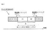
図2は、P1のOFDM信号を示す図である。 FIG. 2 is a diagram illustrating an OFDM signal of P1.
P1のOFDM信号は、1K(=1024)個のシンボルを有効シンボルとして有する。 The OFDM signal of P1 has 1K (= 1024) symbols as effective symbols.
そして、P1のOFDM信号は、有効シンボルAの、先頭側の一部分A1を周波数シフトした信号Cを、有効シンボルの前側にコピーし、かつ、有効シンボルAの残りの部分A2を周波数シフトした信号Bを、有効シンボルの後ろ側にコピーした、サイクリック(cyclic)な構造になっている。 Then, the OFDM signal of P1 is a signal B obtained by copying the signal C obtained by frequency-shifting the first part A1 of the effective symbol A to the front side of the effective symbol A and frequency-shifting the remaining part A2 of the effective symbol A. Is a cyclic structure in which is copied to the back of the effective symbol.
P1のOFDM信号は、853本のサブキャリアを、有効なサブキャリアとして有し、DVB-T2では、その853本のサブキャリアのうちの、384本のサブキャリアに、情報の割り当て(location)がされている。 The OFDM signal of P1 has 853 subcarriers as effective subcarriers, and DVB-T2 has information allocation (location) for 384 subcarriers out of the 853 subcarriers. Has been.
DVB-T2のインプリメンテーションガイドライン(Implementation Guidelines(ETSI TR 102 831 : IG))には、OFDM信号を送信する伝送帯域が、例えば、8MHzである場合、P1によれば、P1のOFDM信号の、上述の384本のサブキャリアのロケーションの相関性を利用して、最大で±500kHzの精度の、「粗い」キャリアずれ量("coarse" carrier frequency offset)の推定が可能であることが記載されている。 In the implementation guidelines of DVB-T2 (Implementation Guidelines (ETSI TR 102 831: IG)), for example, when the transmission band for transmitting an OFDM signal is 8 MHz, according to P1, according to the OFDM signal of P1, It is described that it is possible to estimate a “coarse” carrier frequency offset with accuracy of up to ± 500 kHz using the correlation of the location of 384 subcarriers described above. Yes.
さらに、インプリメンテーションガイドラインには、P1によれば、図2で説明したサイクリックな構造によって、±0.5×サブキャリア間隔の精度の、「細かい」キャリアずれ量("fine" carrier frequency offset)の推定が可能であることが記載されている。 Further, according to P1, according to P1, the cyclic structure described in FIG. 2 is used, and the accuracy of ± 0.5 × subcarrier interval is set to “fine” carrier frequency offset. It is described that estimation is possible.
ここで、DVB-T2では、上述したように、P1のFFTサイズが、1Kサンプル(シンボル)であることが規定されている。 Here, as described above, DVB-T2 specifies that the FFT size of P1 is 1K samples (symbols).
さらに、DVB-T2では、伝送帯域が、例えば、8MHzである場合には、FFTサイズが1KサンプルのP1のサンプリング周期が、7/64μ秒であることが規定されている。 Furthermore, DVB-T2 stipulates that when the transmission band is 8 MHz, for example, the sampling period of P1 with an FFT size of 1K samples is 7/64 μsec.
したがって、伝送帯域が、例えば、8MHzである場合、P1の有効シンボル長Tuは、1024×7/64μ秒である Thus, the transmission band is, for example, if it is 8 MHz, the effective symbol length T u of P1 is a 1024 × 7 / 64μ sec
一方、OFDMシンボルの有効シンボルの長さ(ガードインターバルを含まない長さである有効シンボル長)Tu[秒]と、OFDM信号のサブキャリアのサブキャリア間隔D[Hz]との間には、式D=1/Tuの関係が成り立つ。 On the other hand, between the effective symbol length of OFDM symbols (effective symbol length that does not include the guard interval) Tu [second] and the subcarrier interval D [Hz] of the subcarrier of the OFDM signal, The relationship of the formula D = 1 / T u is established.
したがって、伝送帯域が、例えば、8MHzである場合、P1のサブキャリアのサブキャリア間隔Dは、有効シンボル長Tu=1024×7/64μ秒の逆数である約8929Hzとなる。 Thus, the transmission band is, for example, if it is 8 MHz, the subcarrier spacing D of the subcarriers of P1 becomes the reciprocal of the effective symbol length T u = 1024 × 7 / 64μ sec to about 8,929 Hz.
以上のように、P1のサブキャリア間隔Dは、(約)8929Hzであるから、P1を用いて推定することができる「細かい」キャリアずれ量は、±8929/2Hzの精度となる。 As described above, since the subcarrier interval D of P1 is (about) 8929 Hz, the “fine” carrier shift amount that can be estimated using P1 has an accuracy of ± 8929/2 Hz.
この場合、P1によるキャプチャレンジ、すなわち、P1から得られる「細かい」キャリアずれ量に従ったOFDM信号の補正によって、ディジタル直交復調に用いられるOFDM信号のキャリアを引き込むことのできる範囲は、OFDM信号のキャリアの真値を基準とする±8929/2Hzの範囲内(-8929/2Hzないし+8929/2Hzの範囲内)となる。 In this case, the capture range by P1, that is, the range in which the carrier of the OFDM signal used for digital quadrature demodulation can be drawn by correcting the OFDM signal according to the “fine” carrier shift amount obtained from P1, is the range of the OFDM signal. It is within the range of ± 8929 / 2Hz (within the range of -8929 / 2Hz to + 8929 / 2Hz) with reference to the true value of the carrier.
FFTサイズが1KのP1を用いて推定されるキャリアずれ量によれば、FFTサイズが1KのOFDMシンボルについては、±0.5×サブキャリア間隔Dの範囲内に、キャリアを引き込むことができるので、OFDMシンボルを復調することができる。 According to the carrier shift amount estimated using P1 with an FFT size of 1K, for OFDM symbols with an FFT size of 1K, the carrier can be drawn within a range of ± 0.5 × subcarrier interval D. The symbol can be demodulated.
しかしながら、FFTサイズが1K以外のOFDMシンボル、つまり、DVB-T2では、FFTサイズが、2K,4K,8K,16K、及び、32KそれぞれのOFDMシンボルについては、FFTサイズが1KのP1を用いて推定されるキャリアずれ量によって、±0.5×サブキャリア間隔Dの範囲内に、キャリアを引き込むことができない場合がある。 However, OFDM symbols with FFT sizes other than 1K, that is, with DVB-T2, for OFDM symbols with FFT sizes of 2K, 4K, 8K, 16K, and 32K, estimation is performed using P1 with an FFT size of 1K. Depending on the amount of carrier shift, carriers may not be drawn within the range of ± 0.5 × subcarrier interval D.
すなわち、例えば、伝送帯域が8MHzである場合には、FFTサイズが32KのOFDMシンボルのサブキャリア間隔Dは、279Hzである。 That is, for example, when the transmission band is 8 MHz, the subcarrier interval D of an OFDM symbol having an FFT size of 32K is 279 Hz.
したがって、FFTサイズが1KのP1を用いて推定されるキャリアずれ量によって、±8929/2Hzの範囲内に、キャリアを引き込むことができても、依然として、キャリアずれ量(の大きさ)が、FFTサイズが32KのOFDMシンボルのサブキャリア間隔Dである279Hzの±0.5倍の範囲を越えていることがある。
Therefore, even if the carrier can be drawn in the range of ± 8929/2 Hz by the carrier deviation estimated using P1 with an FFT size of 1K, the carrier deviation (the magnitude) still remains. The size may exceed the range of ± 0.5
このように、OFDMシンボルのサブキャリア間隔Dの±0.5倍を越えるキャリアずれ量(1サブキャリア以上のキャリアずれ量)が生じたままでは、OFDMシンボルを復調することができない。 As described above, the OFDM symbol cannot be demodulated if the carrier shift amount (carrier shift amount of one subcarrier or more) exceeding ± 0.5 times the subcarrier interval D of the OFDM symbol is generated.
なお、マルチパスや、CW(Continuous Wave)等の外乱が存在する環境では、P1を誤検出しやすく、そのような誤検出をしたP1による「細かい」キャリアずれ量の推定の精度は、著しく劣化する。その結果、FFTサイズが、2K,4K,8K,16K、及び、32KそれぞれのOFDMシンボルについては、復調することができなくなる可能性が高くなる。 In an environment where there are disturbances such as multipath and CW (Continuous Wave), it is easy to detect P1 erroneously, and the accuracy of the estimation of the “fine” carrier shift amount due to such erroneous detection P1 is significantly degraded. To do. As a result, there is a high possibility that the OFDM symbols having FFT sizes of 2K, 4K, 8K, 16K, and 32K cannot be demodulated.
以上のように、FFTサイズが、2K,4K,8K,16K、及び、32KそれぞれのOFDMシンボルについては、FFTサイズが1KのP1を用いて推定されるキャリアずれ量によって、±0.5×サブキャリア間隔Dの範囲内に、キャリアを引き込むことができず、その結果、OFDMシンボルを復調することができない場合がある。 As described above, for OFDM symbols with FFT sizes of 2K, 4K, 8K, 16K, and 32K, ± 0.5 × subcarrier spacing depending on the amount of carrier deviation estimated using P1 with an FFT size of 1K In some cases, the carrier cannot be drawn into the range of D, and as a result, the OFDM symbol cannot be demodulated.
FFTサイズが、2K,4K,8K,16K、及び、32KそれぞれのOFDMシンボルについて、±0.5×サブキャリア間隔Dの範囲内に、キャリアを引き込むためには、P1を用いたキャリアずれ量の推定に加えて、2K,4K,8K,16K、及び、32KそれぞれのFFTサイズにとっての「粗い」キャリアずれ量の推定を行う必要がある。 For OFDM symbols with FFT sizes of 2K, 4K, 8K, 16K, and 32K, in order to draw carriers within the range of ± 0.5 × subcarrier interval D, estimate the carrier shift amount using P1. In addition, it is necessary to estimate a “coarse” carrier shift amount for each of the 2K, 4K, 8K, 16K, and 32K FFT sizes.
インプリメンテーションガイドラインでは、各FFTサイズにとっての「粗い」キャリアずれ量を推定する方法として、DVB-T(第2世代欧州地上ディジタル放送規格)等で一般的な方法が紹介されている。 In the implementation guidelines, a general method such as DVB-T (2nd generation European terrestrial digital broadcasting standard) is introduced as a method of estimating a “coarse” carrier shift amount for each FFT size.
すなわち、インプリメンテーションガイドラインでは、CPの配置(location)を利用したキャリア周波数オフセット(Carrier Frequency Offset)推定法や、SPのインパルス応答を利用したキャリア周波数オフセット推定法が紹介されている。 That is, the implementation guideline introduces a carrier frequency offset estimation method using CP location and a carrier frequency offset estimation method using SP impulse response.
各FFTサイズのOFDMシンボルについて、±0.5×サブキャリア間隔Dの範囲内に、キャリアを引き込んだ後は、各FFTサイズにとっての「細かい」キャリアずれ量の推定は、例えば、ガードインターバル長を利用した相関器や、CPのOFDMシンボル方向(時間)の位相差を利用した相関器等を用いて行うことができる。 For each FFT size OFDM symbol, after drawing the carrier within the range of ± 0.5 × subcarrier interval D, estimation of the “fine” carrier shift amount for each FFT size uses, for example, a guard interval length This can be performed using a correlator, a correlator using a phase difference in the OFDM OFDM symbol direction (time), or the like.
ところで、DVB-T2のOFDM信号を受信する受信装置では、いわゆるチャンネルスキャン(channel scan)時に、最初に、P1を検出したT2フレームにおいて、P1シグナリングの復調、及び、ガードインターバル長の推定が行われる。 By the way, in a receiver that receives an OFDM signal of DVB-T2, at the time of so-called channel scan, first, demodulation of P1 signaling and estimation of guard interval length are performed in a T2 frame in which P1 is detected. .
その後、受信装置では、P2のFFTサイズを認識し、次のT2フレームのP2のFFT演算の開始位置(FFT Window トリガ位置)を検出することが可能となる。そして、受信装置では、P2のFFT演算を行い、周波数領域のOFDM信号が得られるようになる。周波数領域のOFDM信号が得られるようになると、P2に含まれるL1プレシグナリング(図1)の復調が可能となり、以下、データの復調が可能となる。 After that, the receiving apparatus can recognize the FFT size of P2 and detect the start position (FFT Window trigger position) of the P2 FFT calculation in the next T2 frame. Then, the receiving apparatus performs a P2 FFT operation to obtain an OFDM signal in the frequency domain. When an OFDM signal in the frequency domain is obtained, L1 pre-signaling (FIG. 1) included in P2 can be demodulated, and data can be demodulated below.
ここで、P2のFFTサイズが、2K,4K,8K,16K、又は、32Kであり、つまり、P2のキャリア間隔が、P1のキャリア間隔より狭く、さらに、P1を用いたキャリアずれ量の推定の精度が低下している場合には、OFDM信号の補正のために、P2のFFTサイズにとっての「粗い」キャリアずれ量の推定を行う必要があることがある。 Here, the FFT size of P2 is 2K, 4K, 8K, 16K, or 32K, that is, the carrier interval of P2 is narrower than the carrier interval of P1, and further, the amount of carrier deviation estimation using P1 is estimated. When the accuracy is low, it may be necessary to estimate a “coarse” carrier shift amount for the FFT size of P2 in order to correct the OFDM signal.
例えば、T2フレームに、2以上のP2が含まれている場合には、隣接する2つのP2の相関に基づいて、P2のFFTサイズにとっての「粗い」キャリアずれ量の推定を行うことができる。 For example, when two or more P2s are included in the T2 frame, the “coarse” carrier shift amount for the FFT size of P2 can be estimated based on the correlation between two adjacent P2s.
しかしながら、T2フレームに、1つのP2しか含まれていない場合には、隣接する2つのP2の相関を求めることができず、例えば、2以上のP2が含まれているT2フレームが送信されてくるまで、隣接する2つのP2の相関に基づく、「粗い」キャリアずれ量の推定を行うことができない。 However, when only one P2 is included in the T2 frame, the correlation between two adjacent P2s cannot be obtained, and for example, a T2 frame including two or more P2s is transmitted. Until now, it is not possible to estimate the “coarse” carrier shift amount based on the correlation between two adjacent P2.
なお、P2のFFTサイズにとっての「粗い」キャリアずれ量の推定は、例えば、CPの配置を利用したキャリア周波数オフセット推定法によって行うことができる。 The estimation of the “coarse” carrier shift amount for the FFT size of P2 can be performed by, for example, a carrier frequency offset estimation method using the arrangement of CPs.
但し、DVB-T2では、CPの配置として、8種類の配置パターンが定義されており、OFDM信号に含まれるCPの配置パターンが、8種類の配置パターンのうちのいずれであるのかの情報は、P2のL1プレシグナリング(図1)に含まれる。したがって、L1プレシグナリングを復調することができていないチャンネルスキャン時に、CPの配置を利用したキャリア周波数オフセット推定法は、採用することができない。 However, in DVB-T2, eight types of arrangement patterns are defined as CP arrangements, and information on which of the eight types of arrangement patterns is included in the OFDM signal is as follows. Included in P2 L1 pre-signaling (FIG. 1). Therefore, the carrier frequency offset estimation method using the CP arrangement cannot be employed during channel scanning where L1 pre-signaling cannot be demodulated.
本発明は、このような状況に鑑みてなされたものであり、キャリアずれ量を、必要な精度で、迅速に推定することができるようにするものである。 The present invention has been made in view of such a situation, and makes it possible to quickly estimate the carrier shift amount with the required accuracy.
本発明の第1の側面の信号処理装置は、OFDM(Orthogonal Frequency Division Multiplexing)信号を復調するときに用いられるキャリアの誤差であるキャリアずれ量を検出するキャリアずれ量検出処理を行う処理手段と、前記キャリアずれ量に従い、前記OFDM信号を補正する補正手段とを備え、前記OFDM信号は、第1のプリアンブル信号と、前記第1のプリアンブル信号のサブキャリアの間隔よりも狭い所定の間隔のサブキャリアの第2のプリアンブル信号とを含み、前記第2のプリアンブル信号は、所定数のサブキャリアごとに、既知の信号であるパイロット信号を含み、前記処理手段は、前記第2のプリアンブル信号が有するサブキャリアの位相を検出する位相検出手段と、IQコンスタレーションの原点を中心とする円の円周上の、前記サブキャリアの位相だけ回転した位置に、前記サブキャリアをマッピングし、前記原点、及び、前記サブキャリアをマッピングしたマッピング点を、始点と終点とする位相ベクトルを求めるマッピング手段と、所定のサブキャリア数分のキャリアずれ量を表すオフセット量の最小値から、前記オフセット量の最大値までの範囲の複数の前記オフセット量それぞれについて、前記第2のプリアンブル信号の先頭のサブキャリアから、前記オフセット量だけずれたずらし位置を始点とし、前記ずらし位置から、前記所定数ごとのサブキャリアの前記位相ベクトルの総和を、前記サブキャリアの相関として演算するベクトル総和演算手段と、複数の前記オフセット量それぞれについて得られる前記位相ベクトルの総和の中の、大きさが最大の総和を検出し、前記最大の総和に対応する前記オフセット量を、前記キャリアずれ量として検出する最大値検出手段とを有し、1つの前記第2のプリアンブル信号に含まれる前記サブキャリアの相関を用いて、前記キャリアずれ量を検出する信号処理装置である。 The signal processing apparatus according to the first aspect of the present invention includes processing means for performing carrier shift amount detection processing for detecting a carrier shift amount that is a carrier error used when demodulating an OFDM (Orthogonal Frequency Division Multiplexing) signal; Correction means for correcting the OFDM signal according to the carrier shift amount, wherein the OFDM signal is a subcarrier having a predetermined interval narrower than an interval between the first preamble signal and the subcarriers of the first preamble signal. Second preamble signal, the second preamble signal includes a pilot signal that is a known signal for each predetermined number of subcarriers, and the processing means includes sub-bands included in the second preamble signal. Phase detection means for detecting the phase of the carrier and the phase of the subcarrier on the circumference of the circle centered on the origin of the IQ constellation. Mapping means for mapping the subcarriers to the rotated position, obtaining phase vectors having the origin and mapping points where the subcarriers are mapped as start points and end points, and carrier shifts by a predetermined number of subcarriers For each of the plurality of offset amounts in the range from the minimum value of the offset amount representing the amount to the maximum value of the offset amount, a shift position shifted by the offset amount from the first subcarrier of the second preamble signal. A vector sum calculating means for calculating a sum of the phase vectors of the predetermined number of subcarriers as a correlation of the subcarriers from the shift position, and a phase vector obtained for each of the offset amounts; Detect the sum of the largest sum among the sums. Corresponding to the offset amount, and a maximum value detecting means for detecting as said carrier shift amount using a correlation of the subcarriers included in one of said second preamble signal, detects the carrier shift amount It is a signal processing device.
本発明の第1の側面の信号処理方法は、信号処理装置が、OFDM(Orthogonal Frequency Division Multiplexing)信号を復調するときに用いられるキャリアの誤差であるキャリアずれ量を検出するキャリアずれ量検出処理を行い、前記キャリアずれ量に従い、前記OFDM信号を補正するステップを含み、前記OFDM信号は、第1のプリアンブル信号と、前記第1のプリアンブル信号のサブキャリアの間隔よりも狭い所定の間隔のサブキャリアの第2のプリアンブル信号とを含み、前記第2のプリアンブル信号は、所定数のサブキャリアごとに、既知の信号であるパイロット信号を含み、前記キャリアずれ量検出処理は、前記第2のプリアンブル信号が有するサブキャリアの位相を検出し、IQコンスタレーションの原点を中心とする円の円周上の、前記サブキャリアの位相だけ回転した位置に、前記サブキャリアをマッピングし、前記原点、及び、前記サブキャリアをマッピングしたマッピング点を、始点と終点とする位相ベクトルを求め、所定のサブキャリア数分のキャリアずれ量を表すオフセット量の最小値から、前記オフセット量の最大値までの範囲の複数の前記オフセット量それぞれについて、前記第2のプリアンブル信号の先頭のサブキャリアから、前記オフセット量だけずれたずらし位置を始点とし、前記ずらし位置から、前記所定数ごとのサブキャリアの前記位相ベクトルの総和を、前記サブキャリアの相関として演算し、複数の前記オフセット量それぞれについて得られる前記位相ベクトルの総和の中の、大きさが最大の総和を検出し、前記最大の総和に対応する前記オフセット量を、前記キャリアずれ量として検出するステップを含み、1つの前記第2のプリアンブル信号に含まれる前記サブキャリアの相関を用いて、前記キャリアずれ量を検出する信号処理方法である。 The signal processing method according to the first aspect of the present invention includes a carrier shift amount detection process in which a signal processing device detects a carrier shift amount that is a carrier error used when demodulating an OFDM (Orthogonal Frequency Division Multiplexing) signal. And correcting the OFDM signal according to the carrier shift amount, wherein the OFDM signal is a subcarrier having a predetermined interval narrower than an interval between the first preamble signal and the subcarriers of the first preamble signal. The second preamble signal includes a pilot signal that is a known signal for each predetermined number of subcarriers, and the carrier shift amount detection processing includes the second preamble signal. The phase of the subcarriers on the circumference of a circle centering on the origin of the IQ constellation is detected. The subcarrier is mapped at a position rotated by a distance, and a phase vector having the origin and the mapping point where the subcarrier is mapped as a start point and an end point is obtained, and represents a carrier shift amount corresponding to a predetermined number of subcarriers. For each of a plurality of offset amounts in the range from the minimum value of the offset amount to the maximum value of the offset amount, a starting position is a shift position shifted from the head subcarrier of the second preamble signal by the offset amount, The sum of the phase vectors of the predetermined number of subcarriers is calculated as the correlation of the subcarriers from the shifted position, and the magnitude of the sum of the phase vectors obtained for each of the plurality of offset amounts is The maximum sum is detected, and the offset amount corresponding to the maximum sum is calculated as the offset. Comprising detecting as Azure amount using a correlation of the subcarriers included in one of said second preamble signal, a signal processing method for detecting the carrier shift amount.
本発明の第2の側面の受信システムは、伝送路を介して取得した信号に対して、前記伝送路で生じる誤りを訂正する処理を少なくとも含む伝送路復号処理を施す伝送路復号処理部と、前記伝送路復号処理が施された信号に対して、圧縮された情報を元の情報に伸張する処理を少なくとも含む情報源復号処理を施す情報源復号処理部とを含み、前記伝送路を介して取得した信号は、情報を圧縮する圧縮符号化と、前記伝送路で生じる誤りを訂正するための誤り訂正符号化とを、少なくとも行うことで得られたOFDM(Orthogonal Frequency Division Multiplexing)信号であり、前記伝送路復号処理部は、OFDM信号を復調するときに用いられるキャリアの誤差であるキャリアずれ量を検出するキャリアずれ量検出処理を行う処理手段と、前記キャリアずれ量に従い、前記OFDM信号を補正する補正手段とを備え、前記OFDM信号は、第1のプリアンブル信号と、前記第1のプリアンブル信号のサブキャリアの間隔よりも狭い所定の間隔のサブキャリアの第2のプリアンブル信号とを含み、前記第2のプリアンブル信号は、所定数のサブキャリアごとに、既知の信号であるパイロット信号を含み、前記処理手段は、前記第2のプリアンブル信号が有するサブキャリアの位相を検出する位相検出手段と、IQコンスタレーションの原点を中心とする円の円周上の、前記サブキャリアの位相だけ回転した位置に、前記サブキャリアをマッピングし、前記原点、及び、前記サブキャリアをマッピングしたマッピング点を、始点と終点とする位相ベクトルを求めるマッピング手段と、所定のサブキャリア数分のキャリアずれ量を表すオフセット量の最小値から、前記オフセット量の最大値までの範囲の複数の前記オフセット量それぞれについて、前記第2のプリアンブル信号の先頭のサブキャリアから、前記オフセット量だけずれたずらし位置を始点とし、前記ずらし位置から、前記所定数ごとのサブキャリアの前記位相ベクトルの総和を、前記サブキャリアの相関として演算するベクトル総和演算手段と、複数の前記オフセット量それぞれについて得られる前記位相ベクトルの総和の中の、大きさが最大の総和を検出し、前記最大の総和に対応する前記オフセット量を、前記キャリアずれ量として検出する最大値検出手段とを有し、1つの前記第2のプリアンブル信号に含まれる前記サブキャリアの相関を用いて、前記キャリアずれ量を検出する受信システムである。 The reception system according to the second aspect of the present invention includes a transmission path decoding processing unit that performs transmission path decoding processing including at least processing for correcting an error occurring in the transmission path, on a signal acquired via the transmission path, An information source decoding processing unit that performs an information source decoding process including at least a process of decompressing the compressed information to the original information on the signal subjected to the transmission path decoding process, via the transmission path The acquired signal is an OFDM (Orthogonal Frequency Division Multiplexing) signal obtained by performing at least compression coding for compressing information and error correction coding for correcting an error occurring in the transmission path, The transmission path decoding processing unit is configured to perform a carrier shift amount detection process for detecting a carrier shift amount, which is a carrier error used when demodulating an OFDM signal, according to the carrier shift amount, Correction means for correcting the OFDM signal, the OFDM signal comprising: a first preamble signal; and a second preamble signal of a subcarrier having a predetermined interval narrower than an interval of subcarriers of the first preamble signal. The second preamble signal includes a pilot signal that is a known signal for each predetermined number of subcarriers, and the processing means detects a phase of a subcarrier included in the second preamble signal. The subcarrier is mapped to a position that is rotated by the phase of the subcarrier on the circumference of a circle centered on the origin of the IQ constellation, and the origin and the subcarrier are mapped. A mapping means for obtaining a phase vector having a mapping point as a start point and an end point, and a carrier shift amount corresponding to a predetermined number of subcarriers. For each of the plurality of offset amounts in the range from the minimum value of the offset amount to the maximum value of the offset amount, the start position is a shift position shifted from the head subcarrier of the second preamble signal by the offset amount. , Vector sum calculating means for calculating the sum of the phase vectors of the predetermined number of subcarriers as the correlation of the subcarriers from the shifted position, and a sum of the phase vectors obtained for each of the offset amounts. A maximum value detecting means for detecting a total sum having a maximum magnitude and detecting the offset amount corresponding to the maximum sum as the carrier shift amount, and one second preamble signal The reception system detects the carrier shift amount using the correlation of the included subcarriers.
本発明の第3の側面の受信システムは、伝送路を介して取得した信号に対して、前記伝送路で生じる誤りを訂正する処理を少なくとも含む伝送路復号処理を施す伝送路復号処理部と、前記伝送路復号処理が施された信号に基づいて、画像又は音声を出力する出力部とを含み、前記伝送路を介して取得した信号は、前記伝送路で生じる誤りを訂正するための誤り訂正符号化を、少なくとも行うことで得られたOFDM(Orthogonal Frequency Division Multiplexing)信号であり、前記伝送路復号処理部は、OFDM信号を復調するときに用いられるキャリアの誤差であるキャリアずれ量を検出するキャリアずれ量検出処理を行う処理手段と、前記キャリアずれ量に従い、前記OFDM信号を補正する補正手段とを備え、前記OFDM信号は、第1のプリアンブル信号と、前記第1のプリアンブル信号のサブキャリアの間隔よりも狭い所定の間隔のサブキャリアの第2のプリアンブル信号とを含み、前記第2のプリアンブル信号は、所定数のサブキャリアごとに、既知の信号であるパイロット信号を含み、前記処理手段は、前記第2のプリアンブル信号が有するサブキャリアの位相を検出する位相検出手段と、IQコンスタレーションの原点を中心とする円の円周上の、前記サブキャリアの位相だけ回転した位置に、前記サブキャリアをマッピングし、前記原点、及び、前記サブキャリアをマッピングしたマッピング点を、始点と終点とする位相ベクトルを求めるマッピング手段と、所定のサブキャリア数分のキャリアずれ量を表すオフセット量の最小値から、前記オフセット量の最大値までの範囲の複数の前記オフセット量それぞれについて、前記第2のプリアンブル信号の先頭のサブキャリアから、前記オフセット量だけずれたずらし位置を始点とし、前記ずらし位置から、前記所定数ごとのサブキャリアの前記位相ベクトルの総和を、前記サブキャリアの相関として演算するベクトル総和演算手段と、複数の前記オフセット量それぞれについて得られる前記位相ベクトルの総和の中の、大きさが最大の総和を検出し、前記最大の総和に対応する前記オフセット量を、前記キャリアずれ量として検出する最大値検出手段とを有し、1つの前記第2のプリアンブル信号に含まれる前記サブキャリアの相関を用いて、前記キャリアずれ量を検出する受信システムである。 The reception system according to the third aspect of the present invention includes a transmission path decoding processing unit that performs transmission path decoding processing including at least processing for correcting an error occurring in the transmission path, on a signal acquired via the transmission path, An output unit that outputs an image or sound based on the signal subjected to the transmission path decoding process, and the signal acquired via the transmission path is an error correction for correcting an error occurring in the transmission path An OFDM (Orthogonal Frequency Division Multiplexing) signal obtained by performing at least encoding, and the transmission path decoding processing unit detects a carrier shift amount that is a carrier error used when demodulating the OFDM signal. A processing unit that performs carrier shift amount detection processing; and a correction unit that corrects the OFDM signal according to the carrier shift amount. The OFDM signal includes a first preamble signal and the first preamble signal. A second preamble signal of subcarriers with a predetermined interval narrower than the subcarrier interval of the amble signal, and the second preamble signal includes a pilot signal that is a known signal for each predetermined number of subcarriers. The processing means includes a phase detection means for detecting a phase of the subcarrier included in the second preamble signal, and a rotation of the phase of the subcarrier on the circumference of a circle centered on the origin of the IQ constellation. Mapping means for mapping the subcarrier at the position, and obtaining a phase vector having the origin and the mapping point where the subcarrier is mapped as a start point and an end point, and a carrier shift amount corresponding to a predetermined number of subcarriers. A plurality of the offset amounts ranging from the minimum value of the offset amount to the maximum value of the offset amount For each, starting from a shifted position shifted from the leading subcarrier of the second preamble signal by the offset amount, the sum of the phase vectors of the predetermined number of subcarriers from the shifted position is A vector sum calculating means for calculating as a subcarrier correlation, and detecting the sum having the maximum magnitude among the sums of the phase vectors obtained for each of the plurality of offset amounts, and the offset corresponding to the maximum sum And a maximum value detecting means for detecting the amount of the carrier shift as a carrier shift amount, wherein the carrier shift amount is detected by using the correlation of the subcarriers included in one second preamble signal. .
本発明の第4の側面の受信システムは、伝送路を介して取得した信号に対して、前記伝送路で生じる誤りを訂正する処理を少なくとも含む伝送路復号処理を施す伝送路復号処理部と、前記伝送路復号処理が施された信号を記録する記録部とを含み、前記伝送路を介して取得した信号は、前記伝送路で生じる誤りを訂正するための誤り訂正符号化を、少なくとも行うことで得られたOFDM(Orthogonal Frequency Division Multiplexing)信号であり、前記伝送路復号処理部は、OFDM信号を復調するときに用いられるキャリアの誤差であるキャリアずれ量を検出するキャリアずれ量検出処理を行う処理手段と、前記キャリアずれ量に従い、前記OFDM信号を補正する補正手段とを備え、前記OFDM信号は、第1のプリアンブル信号と、前記第1のプリアンブル信号のサブキャリアの間隔よりも狭い所定の間隔のサブキャリアの第2のプリアンブル信号とを含み、前記第2のプリアンブル信号は、所定数のサブキャリアごとに、既知の信号であるパイロット信号を含み、前記処理手段は、前記第2のプリアンブル信号が有するサブキャリアの位相を検出する位相検出手段と、IQコンスタレーションの原点を中心とする円の円周上の、前記サブキャリアの位相だけ回転した位置に、前記サブキャリアをマッピングし、前記原点、及び、前記サブキャリアをマッピングしたマッピング点を、始点と終点とする位相ベクトルを求めるマッピング手段と、所定のサブキャリア数分のキャリアずれ量を表すオフセット量の最小値から、前記オフセット量の最大値までの範囲の複数の前記オフセット量それぞれについて、前記第2のプリアンブル信号の先頭のサブキャリアから、前記オフセット量だけずれたずらし位置を始点とし、前記ずらし位置から、前記所定数ごとのサブキャリアの前記位相ベクトルの総和を、前記サブキャリアの相関として演算するベクトル総和演算手段と、複数の前記オフセット量それぞれについて得られる前記位相ベクトルの総和の中の、大きさが最大の総和を検出し、前記最大の総和に対応する前記オフセット量を、前記キャリアずれ量として検出する最大値検出手段とを有し、1つの前記第2のプリアンブル信号に含まれる前記サブキャリアの相関を用いて、前記キャリアずれ量を検出する受信システムである。 A reception system according to a fourth aspect of the present invention includes a transmission path decoding processing unit that performs transmission path decoding processing including at least processing for correcting an error occurring in the transmission path, on a signal acquired via the transmission path, Including a recording unit that records the signal subjected to the transmission path decoding process, and the signal acquired via the transmission path is at least subjected to error correction coding for correcting an error occurring in the transmission path The OFDM (Orthogonal Frequency Division Multiplexing) signal obtained in step (b), and the transmission path decoding processing unit performs carrier shift amount detection processing for detecting a carrier shift amount that is a carrier error used when demodulating the OFDM signal. Processing means, and correction means for correcting the OFDM signal according to the carrier shift amount. The OFDM signal includes a first preamble signal and a sub-carrier of the first preamble signal. A second preamble signal of subcarriers of a predetermined interval narrower than the interval of a, and the second preamble signal includes a pilot signal that is a known signal for each predetermined number of subcarriers, Means for detecting a phase of a subcarrier included in the second preamble signal; and a position on the circumference of a circle centered on the origin of the IQ constellation and rotated by the phase of the subcarrier. Mapping means for mapping the subcarriers to obtain a phase vector having the origin and the mapping point to which the subcarriers are mapped as a start point and an end point; and an offset amount representing a carrier shift amount for a predetermined number of subcarriers For each of the plurality of offset amounts in a range from a minimum value to a maximum value of the offset amount, the second amount A vector for calculating the sum of the phase vectors of the predetermined number of subcarriers as a correlation of the subcarriers from the shifted position, starting from a shifted position shifted from the leading subcarrier of the preamble signal by the offset amount. Sum of the phase vector obtained for each of a plurality of offset amounts is detected as a sum total calculating means, and the offset amount corresponding to the maximum sum is detected as the carrier deviation amount. and a maximum value detecting means for detecting that, by using the correlation of the subcarriers included in one of said second preamble signal, a receiving system for detecting the carrier shift amount.
本発明の第5の側面の受信システムは、伝送路を介して、信号を取得する取得手段と、前記伝送路を介して取得した信号に対して、前記伝送路で生じる誤りを訂正する処理を少なくとも含む伝送路復号処理を施す伝送路復号処理部とを含み、前記伝送路を介して取得した信号は、前記伝送路で生じる誤りを訂正するための誤り訂正符号化を、少なくとも行うことで得られたOFDM(Orthogonal Frequency Division Multiplexing)信号であり、前記伝送路復号処理部は、OFDM信号を復調するときに用いられるキャリアの誤差であるキャリアずれ量を検出するキャリアずれ量検出処理を行う処理手段と、前記キャリアずれ量に従い、前記OFDM信号を補正する補正手段とを備え、前記OFDM信号は、第1のプリアンブル信号と、前記第1のプリアンブル信号のサブキャリアの間隔よりも狭い所定の間隔のサブキャリアの第2のプリアンブル信号とを含み、前記第2のプリアンブル信号は、所定数のサブキャリアごとに、既知の信号であるパイロット信号を含み、前記処理手段は、前記第2のプリアンブル信号が有するサブキャリアの位相を検出する位相検出手段と、IQコンスタレーションの原点を中心とする円の円周上の、前記サブキャリアの位相だけ回転した位置に、前記サブキャリアをマッピングし、前記原点、及び、前記サブキャリアをマッピングしたマッピング点を、始点と終点とする位相ベクトルを求めるマッピング手段と、所定のサブキャリア数分のキャリアずれ量を表すオフセット量の最小値から、前記オフセット量の最大値までの範囲の複数の前記オフセット量それぞれについて、前記第2のプリアンブル信号の先頭のサブキャリアから、前記オフセット量だけずれたずらし位置を始点とし、前記ずらし位置から、前記所定数ごとのサブキャリアの前記位相ベクトルの総和を、前記サブキャリアの相関として演算するベクトル総和演算手段と、複数の前記オフセット量それぞれについて得られる前記位相ベクトルの総和の中の、大きさが最大の総和を検出し、前記最大の総和に対応する前記オフセット量を、前記キャリアずれ量として検出する最大値検出手段とを有し、1つの前記第2のプリアンブル信号に含まれる前記サブキャリアの相関を用いて、前記キャリアずれ量を検出する受信システムである。 A receiving system according to a fifth aspect of the present invention includes an acquisition unit that acquires a signal via a transmission line, and a process that corrects an error occurring in the transmission line with respect to the signal acquired via the transmission line. A signal obtained through the transmission path is obtained by performing at least error correction coding for correcting an error occurring in the transmission path. OFDM (Orthogonal Frequency Division Multiplexing) signal, and the transmission path decoding processing unit performs a carrier shift amount detection process for detecting a carrier shift amount that is a carrier error used when demodulating an OFDM signal And correction means for correcting the OFDM signal in accordance with the carrier shift amount, wherein the OFDM signal includes a first preamble signal and subcarriers of the first preamble signal. A second preamble signal of subcarriers of a predetermined interval narrower than the interval, and the second preamble signal includes a pilot signal that is a known signal for each predetermined number of subcarriers, and the processing means , Phase detection means for detecting the phase of the subcarrier included in the second preamble signal, and a position rotated by the phase of the subcarrier on the circumference of a circle centered on the origin of the IQ constellation. Mapping means for mapping a carrier and obtaining a phase vector having a mapping point where the origin and the subcarrier are mapped as a start point and an end point, and a minimum offset amount representing a carrier shift amount for a predetermined number of subcarriers To each of a plurality of the offset amounts in a range from the offset amount to the maximum value. A vector for calculating the sum of the phase vectors of the predetermined number of subcarriers as a correlation of the subcarriers from the shifted position, starting from a shifted position shifted from the leading subcarrier of the umble signal by the offset amount. Sum of the phase vector obtained for each of a plurality of offset amounts is detected as a sum total calculating means, and the offset amount corresponding to the maximum sum is detected as the carrier deviation amount. and a maximum value detecting means for detecting that, by using the correlation of the subcarriers included in one of said second preamble signal, a receiving system for detecting the carrier shift amount.
本発明の第1ないし第5の側面においては、OFDM(Orthogonal Frequency Division Multiplexing)信号を復調するときに用いられるキャリアの誤差であるキャリアずれ量を検出するキャリアずれ量検出処理が行われ、前記キャリアずれ量に従い、前記OFDM信号が補正される。前記OFDM信号は、第1のプリアンブル信号と、前記第1のプリアンブル信号のサブキャリアの間隔よりも狭い所定の間隔のサブキャリアの第2のプリアンブル信号とを含み、前記第2のプリアンブル信号は、所定数のサブキャリアごとに、既知の信号であるパイロット信号を含んでいる。前記キャリアずれ量の検出では、1つの前記第2のプリアンブル信号に含まれる前記サブキャリアの相関を用いて、前記キャリアずれ量が検出される。すなわち、前記キャリアずれ量の検出では、前記第2のプリアンブル信号が有するサブキャリアの位相が検出され、IQコンスタレーションの原点を中心とする円の円周上の、前記サブキャリアの位相だけ回転した位置に、前記サブキャリアがマッピングされて、前記原点、及び、前記サブキャリアをマッピングしたマッピング点を、始点と終点とする位相ベクトルが求められる。さらに、所定のサブキャリア数分のキャリアずれ量を表すオフセット量の最小値から、前記オフセット量の最大値までの範囲の複数の前記オフセット量それぞれについて、前記第2のプリアンブル信号の先頭のサブキャリアから、前記オフセット量だけずれたずらし位置を始点とし、前記ずらし位置から、前記所定数ごとのサブキャリアの前記位相ベクトルの総和が、前記サブキャリアの相関として演算され、複数の前記オフセット量それぞれについて得られる前記位相ベクトルの総和の中の、大きさが最大の総和が検出され、前記最大の総和に対応する前記オフセット量が、前記キャリアずれ量として検出される。 In the first to fifth aspects of the present invention, carrier shift amount detection processing for detecting a carrier shift amount, which is a carrier error used when demodulating an OFDM (Orthogonal Frequency Division Multiplexing) signal, is performed. The OFDM signal is corrected according to the amount of deviation. The OFDM signal includes a first preamble signal and a second preamble signal of subcarriers having a predetermined interval narrower than an interval of subcarriers of the first preamble signal, and the second preamble signal is A pilot signal which is a known signal is included for each predetermined number of subcarriers. In the detection of the carrier shift amount, the carrier shift amount is detected using the correlation of the subcarriers included in one second preamble signal. That is, in the detection of the carrier shift amount, the phase of the subcarrier included in the second preamble signal is detected, and the phase is rotated by the phase of the subcarrier on the circumference of a circle centered on the origin of the IQ constellation. The subcarrier is mapped to the position, and a phase vector having the origin and the mapping point where the subcarrier is mapped as a start point and an end point is obtained. Furthermore, for each of the plurality of offset amounts ranging from the minimum value of the offset amount representing the carrier shift amount for a predetermined number of subcarriers to the maximum value of the offset amount, the first subcarrier of the second preamble signal From the shifted position shifted by the offset amount, the sum of the phase vectors of the predetermined number of subcarriers is calculated as the correlation of the subcarriers from the shifted position, and each of the offset amounts is calculated. Of the total sum of the phase vectors obtained, the sum having the maximum magnitude is detected, and the offset amount corresponding to the maximum sum is detected as the carrier shift amount.
なお、信号処理装置、及び、受信システムは、独立した装置であっても良いし、独立した装置を構成する内部のブロックであっても良い。 Note that the signal processing device and the reception system may be independent devices, or may be internal blocks constituting the independent devices.
本発明の第1ないし第5の側面によれば、キャリアずれ量を推定することができる。すなわち、例えば、キャリアずれ量を、必要な精度で、迅速に推定することができる。 According to the first to fifth aspects of the present invention, the carrier shift amount can be estimated. That is, for example, the carrier shift amount can be quickly estimated with the required accuracy.
[信号処理装置の構成例] [Configuration example of signal processing device]
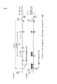
図3は、本発明を適用した信号処理装置の一実施の形態の構成例を示すブロック図である。 FIG. 3 is a block diagram showing a configuration example of an embodiment of a signal processing device to which the present invention is applied.
図3において、信号処理装置は、DVB-T2のOFDM信号を復調する復調装置として機能する。 In FIG. 3, the signal processing device functions as a demodulating device that demodulates the DVB-T2 OFDM signal.
すなわち、図3において、信号処理装置は、直交復調部11、FFT演算部12、オフセット補正部13、バッファ14、オフセット補正部15、プリアンブル処理部16、シンボル同期部17、シンボルタイプ推定部18、及び、プリアンブル処理部19を含む。
That is, in FIG. 3, the signal processing apparatus includes an
直交復調部11には、OFDM信号を送信する送信装置からのOFDM信号(のIF(Intermidiate Frequency)信号)が供給される。
The
直交復調部11は、所定の周波数(キャリア周波数)のキャリア(理想的には、送信装置で用いられるのと同一のキャリア)と、そのキャリアと直交する信号とを用いて、そこに供給されるOFDM信号をディジタル直交復調し、その結果得られるベースバンドのOFDM信号を出力する。
The
ここで、直交復調部11が出力するOFDM信号は、FFT演算がされる前(送信装置側で、IQコンスタレーション上のシンボル(1個のサブキャリアで伝送されるデータ)がIFFT演算された直後)の時間領域の信号であり、以下、OFDM時間領域信号ともいう。
Here, the OFDM signal output from the
OFDM時間領域信号は、実軸成分(I(In Phase)成分)と虚軸成分(Q(Quadrature Phase)成分)とを含む、複素数で表される複素信号である。 The OFDM time domain signal is a complex signal represented by a complex number including a real axis component (I (In Phase) component) and an imaginary axis component (Q (Quadrature Phase) component).
OFDM時間領域信号は、直交復調部11から、FFT演算部12、及び、プリアンブル処理部16に供給される。
The OFDM time domain signal is supplied from the
FFT演算部12は、シンボル同期部17から供給されるFFTトリガ情報に従って、直交復調部11からのOFDM時間領域信号から、FFTサイズ分のOFDM時間領域信号(のサンプル値)を抽出し、DFT(Discrete Fourier Transform)の高速演算であるFFT演算を行う。
In accordance with the FFT trigger information supplied from the
すなわち、シンボル同期部17からFFT演算部12に供給されるFFTトリガ情報は、OFDM時間領域信号について、FFT演算の対象とする区間の開始位置(FFT演算の開始位置)と、その区間のサイズ(FFTサイズ)とを表す。
That is, the FFT trigger information supplied from the
FFT演算部12は、シンボル同期部17からのFFTトリガ情報に従って、そのFFTトリガ情報が表す開始位置から、同じくFFTトリガ情報が表すFFTサイズの区間のOFDM時間領域信号を、FFT演算の対象とする区間(以下、FFT区間ともいう)のOFDM時間領域信号として抽出する。
In accordance with the FFT trigger information from the
これにより、理想的には、OFDM時間領域信号に含まれる1個のOFDMシンボルを構成するシンボルから、ガードインターバル(のシンボル)を除いた、有効シンボル長のシンボルが、FFT区間のOFDM時間領域信号として抽出される。 Thus, ideally, the symbol of the effective symbol length obtained by removing the guard interval (symbol) from the symbols constituting one OFDM symbol included in the OFDM time domain signal is the OFDM time domain signal of the FFT section. Extracted as
そして、FFT演算部12は、FFT区間のOFDM時間領域信号(有効シンボル長のシンボル)のFFT演算を行う。
Then, the
FFT演算部12でのOFDM時間領域信号のFFT演算により、サブキャリアで送信されてきた情報、すなわち、IQコンスタレーション上のシンボルを表すOFDM信号が得られる。
Information transmitted on subcarriers, that is, an OFDM signal representing a symbol on the IQ constellation, is obtained by the FFT operation of the OFDM time domain signal in the
なお、OFDM時間領域信号のFFT演算により得られるOFDM信号は、周波数領域の信号であり、以下、OFDM周波数領域信号ともいう。 Note that the OFDM signal obtained by the FFT calculation of the OFDM time domain signal is a frequency domain signal, and is hereinafter also referred to as an OFDM frequency domain signal.
FFT演算部12は、FFT演算によって得られたOFDM周波数領域信号を、オフセット補正部13に供給する。
The
オフセット補正部13には、FFT演算部12から、OFDM周波数領域信号が供給される他、プリアンブル処理部16から、P1キャリアずれ量が供給される。
The offset
ここで、P1キャリアずれ量は、P1を用いて推定されたキャリアずれ量であり、P1のFFTサイズ(1K)にとっての「粗い」キャリアずれ量と、「細かい」キャリアずれ量とが含まれる。 Here, the P1 carrier shift amount is a carrier shift amount estimated using P1, and includes a “coarse” carrier shift amount and a “fine” carrier shift amount for the FFT size (1K) of P1.
オフセット補正部13は、プリアンブル処理部16からのP1キャリアずれ量に従い、そのP1キャリアずれ量が0になるように、FFT演算部12からのOFDM周波数領域信号を補正する。そして、オフセット補正部13は、補正後のOFDM周波数領域信号を、バッファ14と、プリアンブル処理部19にとに供給する。
The offset
バッファ14は、オフセット補正部13からのOFDM周波数領域信号を、一時記憶し、オフセット補正部15に供給する。
The
オフセット補正部15には、バッファ14から、OFDM周波数領域信号が供給される他、プリアンブル処理部19から、P2キャリアずれ量が供給される。
The offset
ここで、P2キャリアずれ量は、P2を用いて推定されたキャリアずれ量であり、P2のFFTサイズ(1K,2K,4K,8K,16K、又は、32K)にとっての「細かい」キャリアずれ量、すなわち、ここでは、±0.5×サブキャリア間隔Dの範囲内に、(直交復調部11で用いられる)キャリアを(相対的に)引き込むことができるキャリアずれ量である。 Here, the P2 carrier deviation amount is the carrier deviation amount estimated using P2, and the “fine” carrier deviation amount for the FFT size (1K, 2K, 4K, 8K, 16K, or 32K) of P2, That is, here, it is the carrier deviation amount that can draw (relatively) the carrier (used in the orthogonal demodulation unit 11) within the range of ± 0.5 × subcarrier interval D.
オフセット補正部15は、プリアンブル処理部19からのP2キャリアずれ量に従い、そのP2キャリアずれ量が0になるように、バッファ14からのOFDM周波数領域信号を補正する。そして、オフセット補正部15は、補正後のOFDM周波数領域信号を、例えば、等化や誤り訂正等の必要な処理を行う図示せぬブロックに供給する。
The offset
プリアンブル処理部16は、直交復調部11から供給されるOFDM時間領域信号から、第1のプリアンブル信号の一例であるP1を検出し、そのP1を用いた「粗い」キャリアずれ量の推定、及び、「細かい」キャリアずれ量の推定を行う。
The
そして、プリアンブル処理部16は、P1を用いた「粗い」キャリアずれ量の推定、及び、「細かい」キャリアずれ量の推定によって得られる、P1のFFTサイズ(1K)にとっての「粗い」キャリアずれ量と、「細かい」キャリアずれ量とを含むP1キャリアずれ量を、オフセット補正部13に供給する。
Then, the
また、プリアンブル処理部16は、P1に含まれるS1及びS2を抽出し、プリアンブル処理部19に供給する。
In addition, the
さらに、プリアンブル処理部16は、直交復調部11からのOFDM時間領域信号に含まれる、そのOFDM時間領域信号上のP1の位置を表すP1位置情報や、P1に含まれるS1及びS2から認識されるFFTサイズ、その他、OFDMシンボルの境界の位置の推定に必要な情報等を、シンボル同期部17に供給する。
Further, the
シンボル同期部17は、プリアンブル処理部16からのP1位置情報やFFTサイズから、FFTトリガ情報を生成し、FFT演算部12に供給する。
The
また、シンボル同期部17は、プリアンブル処理部16からの情報から、OFDMシンボルの境界の位置(境界位置)を推定し、その境界の位置を表す信号を、シンボル同期信号として、シンボルタイプ推定部18に供給する。
Further, the
シンボルタイプ推定部18は、シンボル同期部17からのシンボル同期信号等に基づいて、オフセット補正部13からプリアンブル処理部19に供給されるOFDM周波数領域信号のOFDMシンボルのシンボルタイプを推定し、プリアンブル処理部19に供給する。
The symbol
ここで、シンボルタイプは、OFDM周波数領域信号のOFDMシンボルが、P1,P2、若しくは、データのOFDMシンボル、又は、FCS(Frame Closing Symbol)であること表す。 Here, the symbol type represents that the OFDM symbol of the OFDM frequency domain signal is P1, P2, or an OFDM symbol of data, or FCS (Frame Closing Symbol).
プリアンブル処理部19は、オフセット補正部13から供給されるOFDM周波数領域信号に含まれる、第1のプリアンブル信号のサブキャリアの間隔よりも狭い所定の間隔のサブキャリアの第2のプリアンブル信号の一例であるP2のFFTサイズにとっての「粗い」キャリアずれ量を推定(検出)するキャリアずれ量検出処理を行う。
The
すなわち、プリアンブル処理部19は、シンボルタイプ推定部18からのシンボルタイプに基づき、オフセット補正部13から供給されるOFDM周波数領域信号に含まれるP2を検出する。
That is, the
さらに、プリアンブル処理部19は、プリアンブル処理部16からのS1及びS2から、オフセット補正部13から供給されるOFDM周波数領域信号に含まれるP2のFFTサイズを認識し、そのFFTサイズにとっての「粗い」キャリアずれ量の推定を行う。
Further, the
そして、プリアンブル処理部19は、P2のFFTサイズにとっての「粗い」キャリアずれ量を、P2キャリアずれ量として、オフセット補正部15に供給する。
Then, the
ここで、プリアンブル処理部19は、P2のFFTサイズにとっての「粗い」キャリアずれ量の推定を、1つのP2、すなわち、1OFDMシンボルのP2に含まれるサブキャリアの相関を用いて、後述するように行う。
Here, the
これにより、プリアンブル処理部19では、T2フレームに、1つのP2しか含まれていない場合であっても、キャリアずれ量を、P2を復調するのに必要な精度で、迅速に推定することができる。
Thereby, even if the
なお、プリアンブル処理部19では、T2フレームに、複数(個のOFDMシンボル)のP2が含まれている場合には、キャリアずれ量の推定は、その複数のP2のうちの、1つのP2を用いて行うこともできるし、複数のP2のうちの、2以上のP2を用いて行うこともできる。
In the
プリアンブル処理部19での、1つのP2に含まれるサブキャリアの相関を用いた、P2のFFTサイズにとっての「粗い」キャリアずれ量の推定の方法としては、第1、第2、及び、第3の3つの推定方法がある。
As a method of estimating the “coarse” carrier shift amount for the FFT size of P2 using the correlation of subcarriers included in one P2 in the
第1ないし第3の推定方法は、P2に含まれる、所定数のサブキャリアごとのサブキャリアの相関を用いる点で共通する。 The first to third estimation methods are common in that the correlation of subcarriers for each predetermined number of subcarriers included in P2 is used.
但し、第1の推定方法は、サブキャリア(シンボル)のパワーに対応するパワー値を、第2の推定方法は、サブキャリアの位相を、第3の推定方法は、サブキャリアの位相差を、それぞれ利用して、サブキャリアの相関を演算する点で、第1ないし第3の推定方法は異なる。 However, the first estimation method uses the power value corresponding to the power of the subcarrier (symbol), the second estimation method uses the subcarrier phase, the third estimation method uses the subcarrier phase difference, The first to third estimation methods are different from each other in that the correlation between subcarriers is calculated using each.
[キャリアずれ量の第1の推定方法] [First Method for Estimating Carrier Deviation Amount]
まず、サブキャリアのパワーに対応するパワー値を利用して演算されるサブキャリアの相関を用いて、キャリアずれ量を推定する第1の推定方法について説明する。 First, a first estimation method for estimating a carrier shift amount using subcarrier correlation calculated using a power value corresponding to the power of the subcarrier will be described.
図4は、OFDM周波数領域信号のパワーを示す図である。 FIG. 4 is a diagram illustrating the power of the OFDM frequency domain signal.
なお、図4において、横軸は、OFDM周波数領域信号のサブキャリアを識別するインデクスを表し、周波数に相当する。また、縦軸は、パワーを表す。 In FIG. 4, the horizontal axis represents an index for identifying the subcarrier of the OFDM frequency domain signal, and corresponds to the frequency. The vertical axis represents power.
図1で説明したように、P2では、周期的な位置のサブキャリアに、パイロット信号(P2 pilot)が配置されている。 As described with reference to FIG. 1, in P2, a pilot signal (P2 pilot) is arranged on subcarriers at periodic positions.
すなわち、DVB-T2では、FFTサイズが32Kで、SISO(SISO mode)のP2については、インデクス#kが、式mod(k,6)=0を満たすサブキャリア#kに、パイロット信号を配置し、その他のP2については、インデクス#kが、式mod(k,3)=0を満たすサブキャリア#kに、パイロット信号を配置することが規定されている。 That is, in DVB-T2, the pilot size is assigned to subcarrier #k where the FFT size is 32K and P2 in SISO (SISO mode) index #k satisfies the equation mod (k, 6) = 0. For other P2, it is specified that the pilot signal is allocated to subcarrier #k in which index #k satisfies the equation mod (k, 3) = 0.
ここで、mod(A,B)は、AをBで除算したときの剰余を表す。 Here, mod (A, B) represents a remainder when A is divided by B.
また、インデクス#kとしては、最も低い周波数のサブキャリアに、インデクス#0が付され、以下、サブキャリアの周波数の昇順に、昇順の整数値のインデクス#kが付されている。
In addition, as index #k,
なお、P2において、エクステンデッドキャリア(Extended Carrier)には、すべて、パイロット信号が配置される。また、MISOのP2では、ノーマルキャリア(Normal Carrier)の両端それぞれの2つのサブキャリアには、パイロット信号が配置される。 In P2, pilot signals are allocated to all extended carriers. Further, the MISO of P2, the opposite ends of the two sub-carrier of the normal carrier (No r mal Carrier), a pilot signal is assigned.
以上から、FFTサイズが32Kで、SISOのP2では、少なくとも、サブキャリア#0,#6,・・・,#6n,・・・(nは、0以上の整数)に、パイロット信号が配置されている(以下、サブキャリア#0,#6,・・・,#6n,・・・が、パイロット信号になっている、ともいう)。また、その他のP2では、少なくとも、サブキャリア#0,#3,・・・,#3n,・・・が、パイロット信号になっている。
From the above, the pilot signal is arranged at least on
さらに、DVB-T2では、FFTサイズが32Kで、SISOのP2のパイロット信号のサブキャリアの振幅が、√37/5であること、及び、その他のP2のパイロット信号のサブキャリアの振幅が、√31/5であることが、規定されている。 Furthermore, in DVB-T2, the FFT size is 32K, the amplitude of the subcarrier of the pilot signal of SISO P2 is √37 / 5, and the amplitude of the subcarrier of the pilot signal of other P2 is √ It is specified that it is 31/5.
また、DVB-T2では、OFDM周波数領域信号のデータのサブキャリアの平均パワーが、1.0であることが規定されている。 Also, DVB-T2 stipulates that the average power of subcarriers of OFDM frequency domain signal data is 1.0.
図4は、FFTサイズが32Kで、SISOの(OFDM周波数領域信号の)P2のパワーを示している。 FIG. 4 shows the power of P2 (of an OFDM frequency domain signal) with an FFT size of 32K and SISO.
FFTサイズが32Kで、SISOのP2は、サブキャリア#0ないし#27264の27265本のサブキャリアを、有効なサブキャリアとして有する。
The FFT size is 32K, and P2 of SISO has 27265 subcarriers of
そして、FFTサイズが32Kで、SISOのP2では、上述したように、サブキャリア#0,#6,・・・,#6n,・・・が、パイロット信号になっており、6個のサブキャリアごとに、パイロット信号が配置されている。さらに、パイロット信号のパワーは、振幅(√37/5)の2乗である1.48=(√37/5)2になっている。
In the SISO P2 with an FFT size of 32K, as described above, the
一方、P2において、データのサブキャリアの平均パワーは、上述したように、1.0になっている。 On the other hand, in P2, the average power of data subcarriers is 1.0 as described above.
以上のように、P2のパイロット信号のサブキャリアと、データのサブキャリアとでは、パワーに差(ブースト量差)がある。 As described above, there is a difference in power (boost amount difference) between the P2 pilot signal subcarrier and the data subcarrier.
第1の推定方法では、このように、パイロット信号とデータとで差があるパワーを利用して、サブキャリアの相関を演算する。 In the first estimation method, as described above, the subcarrier correlation is calculated by using the power having a difference between the pilot signal and the data.
ここで、上述したように、FFTサイズが32Kで、SISOのP2では、インデクス#kが、式mod(k,6)=0を満たすサブキャリア#kに、パイロット信号が配置されているので、周期的に、つまり、6個のサブキャリアごとに、パイロット信号が存在する。この、パイロット信号が配置されるサブキャリアの周期(いまの場合、6)を、以下、パイロット周期ともいう。 Here, as described above, since the FFT size is 32K, and the SISO P2, the index #k is allocated to the subcarrier #k that satisfies the equation mod (k, 6) = 0. Periodically, that is, every 6 subcarriers, there is a pilot signal. This period of subcarriers in which pilot signals are arranged (in this case, 6) is hereinafter also referred to as a pilot period.
FFTサイズが32Kで、SISOのP2以外のP2では、インデクス#kが、式mod(k,3)=0を満たすサブキャリア#kに、パイロット信号が配置されるので、パイロット周期は、3となる。 For P2 other than S2 P2 with an FFT size of 32K, the pilot signal is allocated to subcarrier #k with index #k satisfying the equation mod (k, 3) = 0. Become.
図5は、キャリアずれ量が0のP2と、キャリアずれ量が-1のP2とを示す図である。 FIG. 5 is a diagram illustrating P2 having a carrier deviation amount of 0 and P2 having a carrier deviation amount of −1.
なお、図5の横軸と縦軸は、図4の場合と同様である。 The horizontal and vertical axes in FIG. 5 are the same as those in FIG.
ここで、キャリアずれ量の符号(正負)は、サブキャリアの位置(周波数)のずれの方向を表す。すなわち、キャリアずれ量が正である場合には、サブキャリアが、高い周波数の方向にずれていることを表し、キャリアずれ量が負である場合には、サブキャリアが、低い周波数の方向にずれていることを表す。 Here, the sign (positive / negative) of the carrier shift amount represents the direction of shift of the subcarrier position (frequency). That is, when the carrier shift amount is positive, it indicates that the subcarrier is shifted in the high frequency direction, and when the carrier shift amount is negative, the subcarrier is shifted in the low frequency direction. Represents that
また、キャリアずれ量の大きさ(絶対値)は、サブキャリアがずれている大きさを、サブキャリア間隔Dだけのずれを1として表す。 Further, the magnitude (absolute value) of the carrier deviation amount represents the magnitude of deviation of the subcarrier, and the deviation of only the subcarrier interval D is represented as 1.
したがって、キャリアずれ量が-1であるとは、サブキャリアが、低い周波数の方向に、サブキャリア間隔Dだけずれていることを表す。 Therefore, a carrier shift amount of −1 indicates that the subcarriers are shifted by the subcarrier interval D in the direction of lower frequencies.
図5Aは、キャリアずれ量が0のP2を示しており、図5Bは、キャリアずれ量が-1のP2を示している。 FIG. 5A shows P2 with a carrier shift amount of 0, and FIG. 5B shows P2 with a carrier shift amount of -1.
図5A及び図5BのP2は、いずれも、FFTサイズが32Kで、SISOのP2である。 P2 in FIGS. 5A and 5B is an SISO P2 with an FFT size of 32K.
FFTサイズが32Kで、SISOのP2では、上述したように、6個のサブキャリアごとに、パイロット信号が配置されている。キャリアずれ量が、いくつであっても、6個のサブキャリアごとにパイロット信号が配置されていることに影響しない。 In the SISO P2 with an FFT size of 32K, as described above, a pilot signal is arranged for every six subcarriers. Whatever the amount of carrier shift, there is no effect on the pilot signal being arranged for every six subcarriers.
図6は、プリアンブル処理部19(図3)に供給されるOFDM周波数領域信号に含まれるP2(以下、実際のP2ともいう)と、その実際のP2について、サブキャリアの相関の演算の対象となるサブキャリアとを示す図である。 6 shows P2 (hereinafter also referred to as actual P2) included in the OFDM frequency domain signal supplied to the preamble processing unit 19 (FIG. 3), and the subcarrier correlation calculation target for the actual P2. It is a figure which shows the subcarrier which becomes.
すなわち、図6Aは、実際のP2を示している。 That is, FIG. 6A shows actual P2.
図6Aの実際のP2は、図5Bと同一であり、FFTサイズが32Kで、SISOのP2であり、キャリアずれ量が-1になっている。 The actual P2 in FIG. 6A is the same as FIG. 5B, the FFT size is 32K, the SISO P2, and the carrier shift amount is -1.
図6Aの実際のP2では、キャリアずれ量が-1であるために、式mod(k,6)=0を満たすインデクス#kに、キャリアずれ量である-1を加算して得られるインデクス#k'(=k-1)が表す位置(周波数)のサブキャリア#-1,#5,・・・,#6n-1,・・・,#27263に、パイロット信号が配置されている。 In the actual P2 in FIG. 6A, since the carrier shift amount is −1, the index #k obtained by adding −1 which is the carrier shift amount to the index #k satisfying the equation mod (k, 6) = 0. Pilot signals are arranged on subcarriers # -1, # 5,..., # 6n-1,..., # 27263 at positions (frequencies) represented by k ′ (= k−1).
図6Bは、オフセット量offsetだけのキャリアずれ量を仮定した場合に、実際のP2について、サブキャリアの相関の演算の対象となるサブキャリアを示している。 FIG. 6B shows subcarriers to be subjected to subcarrier correlation calculation with respect to actual P2, assuming a carrier shift amount equivalent to the offset amount offset.
オフセット量offsetが、例えば、-2である場合、P2の、式mod(k,6)=0を満たすインデクス#kに、オフセット量offset=-2を加算して得られるインデクス#k'(=k-2)が表す位置のサブキャリア#-2,#4,・・・,#6n-2,・・・,#27262が、サブキャリアの相関の演算の対象となる。 For example, when the offset amount offset is −2, the index #k ′ (=) obtained by adding the offset amount offset = −2 to the index #k of P2 that satisfies the expression mod (k, 6) = 0. Subcarriers # -2, # 4,..., # 6n-2,..., # 27262 at the positions indicated by k-2) are the targets of subcarrier correlation calculation.
また、オフセット量offsetが、例えば、-1である場合、P2の、式mod(k,6)=0を満たすインデクス#kに、オフセット量offset=-1を加算して得られるインデクス#k'(=k-1)が表す位置のサブキャリア#-1,#5,・・・,#6n-1,・・・,#27263が、サブキャリアの相関の演算の対象となる。 Further, when the offset amount offset is −1, for example, the index #k ′ obtained by adding the offset amount offset = −1 to the index #k satisfying the expression mod (k, 6) = 0 of P2 Subcarriers # -1, # 5,..., # 6n-1,..., # 27263 at the position represented by (= k-1) are the targets of subcarrier correlation calculation.
以下、同様に、P2の、式mod(k,6)=0を満たすインデクス#kに、オフセット量offsetを加算して得られるインデクス#k'(=k+offset)が表す位置のサブキャリア#0+offset,#6+offset,・・・,#6n+offset,・・・が、サブキャリアの相関の演算の対象となる。
Hereinafter, similarly, subcarrier # at the position represented by index #k ′ (= k + offset) obtained by adding offset amount offset to index #k satisfying the expression mod (k, 6) = 0 of
すなわち、説明を簡単にするために、キャリアずれ量が0であるP2を基準とすると、あるオフセット量offsetについては、P2の先頭のサブキャリアから、オフセット量offsetだけずれたずらし位置0+offsetを始点とし、そのずらし位置0+offsetから、パイロット周期(所定数)(いまの場合、6)ごとのサブキャリアが、サブキャリアの相関の演算の対象となる。
That is, for the sake of simplicity, when P2 having a carrier deviation amount of 0 is used as a reference, for a certain offset amount offset, a
第1の推定方法では、サブキャリアのパワーに対応するパワー値である、例えば、パワーそのものを用いて、サブキャリアの相関が演算される。 In the first estimation method, the subcarrier correlation is calculated using the power value corresponding to the power of the subcarrier, for example, the power itself.
すなわち、第1の推定方法では、P2の先頭のサブキャリアから、オフセット量offsetだけずれたずらし位置0+offsetを始点とし、そのずらし位置0+offsetから、パイロット周期(所定数)ごとのサブキャリアのパワーの総和が、サブキャリアの相関として演算される。
That is, in the first estimation method, the starting position is shifted
ここで、サブキャリアの相関は、オフセット量offsetを、ある範囲内で変化させ、各値のオフセット量offsetについて求められる。 Here, the correlation between the subcarriers is obtained for the offset amount offset of each value by changing the offset amount offset within a certain range.
以下、オフセット量offsetを変化させる範囲の最小値、及び、最大値を、それぞれ、オフセット量offsetの最小値MIN、及び、最大値MAXともいう。オフセット量offsetの最小値MIN、及び、最大値MAXの求め方については、後述する。 Hereinafter, the minimum value and the maximum value in the range in which the offset amount offset is changed are also referred to as the minimum value MIN and the maximum value MAX of the offset amount offset, respectively. How to obtain the minimum value MIN and the maximum value MAX of the offset amount offset will be described later.
図6Bでは、オフセット量offsetの最小値MIN、及び、最大値MAXを、それぞれ、-2、及び、+2として、-2,-1,0,・・・,+2の各オフセット量offsetについて、サブキャリアの相関としての、パイロット周期である6個ごとのサブキャリアのパワーの総和が演算されている。 In FIG. 6B, the minimum value MIN and the maximum value MAX of the offset amount offset are set to −2 and +2, respectively, and −2, −1,0,. The sum of the power of every six subcarriers, which is the pilot period, is calculated as the subcarrier correlation.
ここで、オフセット量offsetが、図6Aの実際のP2のキャリアずれ量である-1に一致する場合、P2の先頭のサブキャリアから、オフセット量offsetだけずれたずらし位置0+offsetを始点とし、そのずらし位置0+offsetから、パイロット周期である6個ごとのサブキャリアは、いずれも、パイロット信号であるから、そのようなサブキャリアのパワーの総和は、パイロット信号(のサブキャリア)のパワーの総和となる。
Here, when the offset amount offset coincides with −1 which is the actual carrier shift amount of P2 in FIG. 6A, the start position is the
一方、オフセット量offsetが、図6Aの実際のP2のキャリアずれ量である-1に一致しない場合、P2の先頭のサブキャリアから、オフセット量offsetだけずれたずらし位置0+offsetを始点とし、そのずらし位置0+offsetから、パイロット周期である6個ごとのサブキャリアは、いずれも、(パイロット信号ではない)データであるから、そのようなサブキャリアのパワーの総和は、データのサブキャリアのパワーの総和となる。
On the other hand, if the offset amount offset does not coincide with −1, which is the actual carrier shift amount of P2 in FIG. 6A, the
上述したように、FFTサイズが32Kで、SISOのP2のパイロット信号のサブキャリアの振幅は、√37/5であり、その他のP2のパイロット信号のサブキャリアの振幅は、√31/5である。また、OFDM周波数領域信号のデータのサブキャリアの平均パワーは、1.0である。 As described above, the FFT size is 32K, the amplitude of the subcarrier of the pilot signal of SISO P2 is √37 / 5, and the amplitude of the subcarrier of the pilot signal of other P2 is √31 / 5 . Further, the average power of subcarriers of the data of the OFDM frequency domain signal is 1.0.
したがって、P2の先頭のサブキャリアから、オフセット量offsetだけずれたずらし位置0+offsetを始点とし、そのずらし位置0+offsetから、パイロット周期である6個ごとのサブキャリアを対象として求められるサブキャリアの相関としての、パワーの総和は、サブキャリアの相関の演算の対象が、パイロット信号である場合には、大になり、サブキャリアの相関の演算の対象が、データのサブキャリアである場合には、小になる。
Therefore, the subcarriers obtained from the
そこで、第1の推定方法では、オフセット量offsetの最小値MINから、オフセット量offsetの最大値MAXまでの範囲の複数のオフセット量offsetそれぞれについて、P2の先頭のサブキャリアから、オフセット量offsetだけずれたずらし位置を始点とし、そのずらし位置から、パイロット周期ごとの(位置の)サブキャリアのパワー値の総和を、サブキャリアの相関として演算した後、複数のオフセット量offsetそれぞれについて得られるパワーの総和の中の最大値を検出し、そのパワーの総和の最大値に対応するオフセット量offsetを、キャリアずれ量(P2キャリアずれ量)として検出する。 Therefore, in the first estimation method, each offset amount offset in the range from the minimum value MIN of the offset amount offset to the maximum value MAX of the offset amount offset is shifted from the leading subcarrier of P2 by the offset amount offset. Starting from the offset position, the sum of the power values of the subcarriers (of the position) for each pilot period is calculated as the correlation of the subcarriers from the offset position, and then the sum of the power obtained for each of the offset amounts offset The offset value offset corresponding to the maximum value of the total power is detected as the carrier shift amount (P2 carrier shift amount).
[第1の推定方法によりキャリアずれ量を検出するプリアンブル処理部19]
[
図7は、第1の推定方法によりキャリアずれ量を検出するプリアンブル処理部19(図3)の構成例を示すブロック図である。 FIG. 7 is a block diagram illustrating a configuration example of the preamble processing unit 19 (FIG. 3) that detects the carrier shift amount by the first estimation method.
図7では、プリアンブル処理部19は、制御部31、パワー検出部32、総和演算部33、及び、最大値検出部34を含む。
In FIG. 7, the
制御部31には、シンボルタイプ推定部18(図3)からのシンボルタイプと、プリアンブル処理部16からのS1及びS2が供給される。
The control unit 31 is supplied with the symbol type from the symbol type estimation unit 18 (FIG. 3) and S1 and S2 from the
制御部31は、シンボルタイプ推定部18からのシンボルタイプに基づいて、オフセット補正部13(図3)からプリアンブル処理部19に対して、OFDM周波数領域信号に含まれるP2が供給されるタイミングである供給タイミングを認識する。
Based on the symbol type from the symbol
そして、制御部31は、その供給タイミングに供給されるOFDM周波数領域信号、つまり、P2の処理を行うように、プリアンブル処理部19を構成するパワー検出部32、総和演算部33、及び、最大値検出部34を制御する。
And the control part 31 is the OFDM frequency domain signal supplied at the supply timing, that is, the
また、制御部31は、プリアンブル処理部16(図3)からのS1とS2とに基づいて、P2のFFTサイズと、P2の送信の方式(SISO、又はMISO)とを認識する。 Further, the control unit 31 recognizes the FFT size of P2 and the transmission method (SISO or MISO) of P2 based on S1 and S2 from the preamble processing unit 16 (FIG. 3).
そして、制御部31は、P2のFFTサイズと、P2の送信の方式とから、P2のパイロット信号のパイロット周期を認識し、総和演算部33に供給する。
Then, the control unit 31 recognizes the pilot period of the pilot signal of P2 from the FFT size of P2 and the transmission method of P2, and supplies it to the
さらに、制御部31は、パイロット周期を用いて、オフセット量offsetの最小値MINと最大値MAXを求め、総和演算部33に供給する。
Further, the control unit 31 obtains the minimum value MIN and the maximum value MAX of the offset amount offset using the pilot period, and supplies them to the
ここで、上述したように、DVB-T2では、FFTサイズが32Kで、SISOのP2では、パイロット周期が6になっており、その他のP2では、パイロット周期は3になっている。 Here, as described above, in DVB-T2, the FFT size is 32K, the pilot period is 6 in SISO P2, and the pilot period is 3 in other P2.
いま、パイロット周期を、TPと表すこととすると、制御部31は、式MIN=-INT[(TP-1)/2]に従って、最小値MINを求めるとともに、式MAX=+INT[(TP-1)/2]に従って、最大値MAXを求める。ここで、INT[A]は、A以下の最大の整数を表す。 Assuming that the pilot period is expressed as T P , the control unit 31 obtains the minimum value MIN according to the equation MIN = −INT [(T P −1) / 2] and also calculates the equation MAX = + INT [( According to T P −1) / 2], the maximum value MAX is obtained. Here, INT [A] represents the maximum integer less than or equal to A.
パワー検出部32には、オフセット補正部13(図3)からのOFDM周波数領域信号が供給される。
The
パワー検出部32は、オフセット補正部13からのOFDM周波数領域信号に含まれるP2が有するサブキャリアのパワーに対応するパワー値として、例えば、P2の1つのOFDMシンボルの各サブキャリアのパワーそのものを検出し、総和演算部33に供給する。
The
ここで、パワー検出部32では、サブキャリアのパワーではなく、サブキャリアの振幅を、パワー値として検出することができる。この場合、その後の処理は、サブキャリアの振幅を用いて行われる。
Here, the
総和演算部33は、パワー検出部32から供給されるP2の1つのOFDMシンボル(1つのP2)のサブキャリアのパワーを用い、制御部31から供給される最小値MINから最大値MAXまでの範囲の複数のオフセット量offset(=MIN,MIN+1,・・・,MAX-1,MAX)それぞれについて、P2の先頭のサブキャリアから、オフセット量offsetだけずれたずらし位置を始点とし、そのずらし位置から、制御部31から供給されるパイロット周期TPごとのサブキャリアのパワーの総和を、サブキャリアの相関として演算し、最大値検出部34に供給する。
The
最大値検出部34は、総和演算部33から供給される、複数のオフセット量offsetそれぞれについて得られるパワーの総和の中の最大値を検出し、そのパワーの総和の最大値に対応するオフセット量offsetを、P2キャリアずれ量として検出し、オフセット補正部15(図3)に供給する。
The
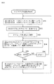
図8は、図7のプリアンブル処理部19が行うキャリアずれ量検出処理を説明するフローチャートである。
FIG. 8 is a flowchart for explaining the carrier shift amount detection process performed by the
制御部31は、シンボルタイプ推定部18(図3)から供給されるシンボルタイプに基づいて、オフセット補正部13(図3)からプリアンブル処理部19に対して、OFDM周波数領域信号に含まれるP2が供給される供給タイミングを認識する。
Based on the symbol type supplied from the symbol type estimation unit 18 (FIG. 3), the control unit 31 sends P2 contained in the OFDM frequency domain signal from the offset correction unit 13 (FIG. 3) to the
そして、供給タイミングとなると、すなわち、オフセット補正部13(図3)からパワー検出部32に供給されるOFDM周波数領域信号がP2となると、ステップS11において、制御部31は、プリアンブル処理部16(図3)からのS1とS2とに基づいて、P2のFFTサイズと、P2の送信の方式(SISO、又はMISO)とを認識する。さらに、制御部31は、P2のFFTサイズと、P2の送信の方式とから、P2のパイロット信号のパイロット周期TPを認識し、総和演算部33に供給する。
When the supply timing comes, that is, when the OFDM frequency domain signal supplied from the offset correction unit 13 (FIG. 3) to the
また、制御部31は、パイロット周期TPを用い、式MIN=-INT[(TP-1)/2]、及び、式MAX=+INT[(TP-1)/2]に従って、それぞれ、オフセット量offsetの最小値MIN、及び、最大値MAXを求め、総和演算部33に供給して、処理は、ステップS11からステップS12に進む。
The control unit 31 uses the pilot period T P, wherein MIN = -INT [(T P -1 ) / 2], and the formula MAX = + according INT [(T P -1) / 2], respectively Then, the minimum value MIN and the maximum value MAX of the offset amount offset are obtained and supplied to the
ステップS12では、パワー検出部32は、オフセット補正部13(図3)から供給されるP2が有する各サブキャリアのパワーを検出し、総和演算部33に供給して、処理は、ステップS13に進む。
In step S12, the
ステップS13では、総和演算部33は、オフセット量offsetを、制御部31からの最小値MINにセットし、処理は、ステップS14に進む。
In step S13, the
ステップS14では、総和演算部33は、オフセット量offsetについて、P2の先頭のサブキャリアから、オフセット量offsetだけずれたずらし位置を始点とし、そのずらし位置から、制御部31から供給されるパイロット周期TPごとのサブキャリアのパワーの総和を、パワー検出部32からのP2の各サブキャリアのパワーを用いて演算する。
In step S14, the
そして、総和演算部33は、オフセット量offsetについて演算したパワーの総和を、最大値検出部34に供給して、処理は、ステップS14からステップS15に進む。
The
ステップS15では、総和演算部33は、オフセット量offsetが、最大値MAXに等しいかどうかを判定する。
In step S15, the
ステップS15において、オフセット量offsetが、最大値MAXに等しくないと判定された場合、すなわち、オフセット量offsetが、最大値MAX未満である場合、処理は、ステップS16に進み、総和演算部33は、オフセット量offsetを1だけインクリメントする。そして、処理は、ステップS16からステップS14に戻り、以下、同様の処理が繰り返される。
If it is determined in step S15 that the offset amount offset is not equal to the maximum value MAX, that is, if the offset amount offset is less than the maximum value MAX, the process proceeds to step S16, and the
また、ステップS15において、オフセット量offsetが、最大値MAXに等しいと判定された場合、すなわち、最小値MINから最大値MAXまでの各値のオフセット量offsetについて、パワーの総和が演算された場合、処理は、ステップS17に進み、最大値検出部34は、総和演算部33から供給される、最小値MINから最大値MAXまでの各値のオフセット量offsetについて演算された、サブキャリアの相関としてのパワーの総和の中の最大値を検出する。
When it is determined in step S15 that the offset amount offset is equal to the maximum value MAX, that is, when the sum of power is calculated for the offset amount offset of each value from the minimum value MIN to the maximum value MAX, The process proceeds to step S17, and the maximum
さらに、最大値検出部34は、パワーの総和の最大値(サブキャリアの相関の最大値)に対応するオフセット量offsetを、P2キャリアずれ量として検出し、オフセット補正部15(図3)に供給する。
Further, the maximum
その後、制御部31は、オフセット補正部13(図3)からプリアンブル処理部19に対して、OFDM周波数領域信号に含まれる次のP2が供給される待って、処理は、ステップS17からステップS11に戻り、以下、同様の処理が行われる。
Thereafter, the control unit 31 waits for the next P2 included in the OFDM frequency domain signal to be supplied from the offset correction unit 13 (FIG. 3) to the
以上のように、最小値MINから最大値MAXまでの各値のオフセット量offsetについて演算された、P2のサブキャリアの相関としてのパワーの総和の中の最大値を検出することで、必要な精度でのキャリアずれ量の推定、すなわち、P2のFFTサイズにとっての「粗い」キャリアずれ量の推定を、迅速に行うことができる。 As described above, the required accuracy is obtained by detecting the maximum value in the sum of power as the correlation of P2 subcarriers calculated for the offset amount offset of each value from the minimum value MIN to the maximum value MAX. In this case, the estimation of the amount of carrier deviation at the time, that is, the estimation of the “rough” carrier deviation amount for the FFT size of P2 can be performed quickly.
なお、図8では、説明を分かりやすくするために、オフセット量offsetを、最小値MINから最大値MAXまでの各値に順次変えて、パイロット周期TPごとのサブキャリアのパワーの総和を演算するようにしているが、実装としては、最小値MINから最大値MAXまでの各値のオフセット量offsetについての、パイロット周期TPごとのサブキャリアのパワーの総和は、並列に演算するようにすることができる。 In FIG. 8, for clarity of description, the offset amount offset, it changed successively from the minimum value (MIN) to the maximum value MAX, calculates the sum of the power values of the subcarriers at intervals of the pilot period T P While being so, the mounting, the minimum value MIN of the offset amount (offset) of each value to a maximum value MAX, the sum of the power of the subcarriers at intervals of the pilot period T P is be adapted to operation in parallel Can do.
また、図8では、T2フレームに、1つのP2しか含まれていないことを前提とし、オフセット量offsetについてのサブキャリアの相関として、1つのP2から、パイロット周期TPごとのサブキャリアのパワーの総和を演算することとしたが、T2フレームに、複数のP2が含まれている場合には、その複数のP2の2つ以上のP2それぞれから、パワーの総和を求め、その2つ以上のP2それぞれから求めたパワーの総和の累積加算値や、リーク積分を行って得られる積分値を、サブキャリアの相関として採用することができる。 Further, in FIG. 8, a T2 frame, assuming that it contains only one P2, as the subcarrier correlation for offset amount offset, from one P2, the power of the subcarriers at intervals of the pilot period T P The sum is calculated, but when a plurality of P2s are included in the T2 frame, the power sum is obtained from each of two or more P2s of the plurality of P2s, and the two or more P2s are calculated. The cumulative addition value of the sum of the powers obtained from each or the integral value obtained by performing leak integration can be adopted as the correlation of the subcarriers.
すなわち、いま、説明を簡単にするために、例えば、T2フレームに、2つのP2が含まれ、その2つのP2それぞれを、第1のP2、及び、第2のP2と呼ぶこととすると、あるオフセット値offsetについて、第1のP2から求められたパワーの総和と、第2のP2から求められたパワーの総和との累積加算値や、リーク積分を行って得られる積分値を、そのオフセット量offsetについてのサブキャリアの相関として採用することができる。 That is, for the sake of simplification of description, for example, a T2 frame includes two P2s, and each of the two P2s is referred to as a first P2 and a second P2. For the offset value offset, the accumulated amount of the power sum obtained from the first P2 and the sum of the power found from the second P2 and the integral value obtained by performing the leak integration are used as the offset amount. It can be employed as a subcarrier correlation for offset.
ここで、リーク積分の対象となるm番目のデータを、x(m)と表すとともに、データx(1)からデータx(m)までを用いたリーク積分を行って得られる積分値を、y(m)と表すこととすると、積分値y(m)は、式y(m)=βx(m)+(1-β)y(m-1)に従って求められる。 Here, the m-th data to be subjected to leak integration is expressed as x (m), and an integral value obtained by performing leak integration using data x (1) to data x (m) is expressed as y When expressed as (m), the integral value y (m) is obtained according to the equation y (m) = βx (m) + (1−β) y (m−1).
また、上述の場合には、P2に含まれるパイロット周期TPごとのサブキャリアのすべてを用いて、サブキャリアの相関を演算することとしたが、サブキャリアの相関の演算には、P2に含まれるパイロット周期TPごとのサブキャリアのうちの、幾つかのサブキャリアを間引いたものを用いることができる。 Further, in the above case, using all of the subcarriers at intervals of the pilot period T P contained in P2, was shown to be computed the correlation of subcarriers, the calculation of the correlation of the subcarriers included in P2 of the subcarriers at intervals of the pilot period T P that can be used as the thinned out several subcarriers.
ところで、第1の推定方法では、オフセット量offsetの最小値MIN、及び、最大値MAXが、それぞれ、式MIN=-INT[(TP-1)/2]、及び、式MAX=+INT[(TP-1)/2]に従って求められる。 By the way, in the first estimation method, the minimum value MIN and the maximum value MAX of the offset amount offset are respectively expressed by the equation MIN = −INT [(T P −1) / 2] and the equation MAX = + INT [ (T P -1) / 2].
そして、第1の推定方法では、最小値MINから最大値MAXまでの範囲以外のキャリアずれ量は、検出することができない。 In the first estimation method, it is not possible to detect a carrier shift amount outside the range from the minimum value MIN to the maximum value MAX.
すなわち、DVB-T2では、パイロット周期TPが、上述したように、6、又は、3であるから、最小値MINと最大値MAXとは、-2と+2、又は、-1と+1となる。 That is, in DVB-T2, since the pilot period TP is 6 or 3, as described above, the minimum value MIN and the maximum value MAX are -2 and +2, or -1 and +1. It becomes.
例えば、いま、パイロット周期TPが、6であり、最小値MINと最大値MAXが、-2と+2である場合に注目すると、P2のキャリアずれ量が、最小値MINから最大値MAXまでの範囲外の、例えば、-3である場合、そのP2のキャリアずれ量が-3である場合と、P2のキャリアずれ量が、例えば、+3(=-3+i×TP)(iは整数)である場合とは、第1の推定方法では区別することができない。 For example, when the pilot period TP is 6 and the minimum value MIN and the maximum value MAX are -2 and +2, the carrier shift amount of P2 is from the minimum value MIN to the maximum value MAX. For example, when the carrier deviation amount of P2 is -3 and the carrier deviation amount of P2 is, for example, +3 (= -3 + i × T P ) (i is an integer) ) Cannot be distinguished by the first estimation method.
また、P2のキャリアずれ量が、最小値MINから最大値MAXまでの範囲外の、例えば、-4である場合、そのP2のキャリアずれ量が-4である場合と、P2のキャリアずれ量が+2(=-4+i×TP)である場合とは、第1の推定方法では、区別することができない。 Also, if the carrier deviation amount of P2 is outside the range from the minimum value MIN to the maximum value MAX, for example, -4, the carrier deviation amount of P2 is -4, and the carrier deviation amount of P2 is The case of +2 (= −4 + i × T P ) cannot be distinguished by the first estimation method.
以上のように、P2のキャリアずれ量が、最小値MINから最大値MAXまでの範囲以外である場合、すなわち、-INT[(TP-1)/2]より小のキャリアずれ量や、+INT[(TP-1)/2]より大のキャリアずれ量が生じている場合、第1の推定方法では、そのキャリアずれ量を、正確に検出することができない。 As described above, when the carrier shift amount of P2 is outside the range from the minimum value MIN to the maximum value MAX, that is, a carrier shift amount smaller than −INT [(T P −1) / 2], + When a carrier deviation amount larger than INT [(T P −1) / 2] occurs, the first estimation method cannot accurately detect the carrier deviation amount.
しかしながら、P1を用いた「粗い」キャリアずれ量の推定の精度が低下している場合には、-INT[(TP-1)/2]より小のキャリアずれ量や、+INT[(TP-1)/2]より大のキャリアずれ量が生じる場合があり、そのようなキャリアずれ量を、正確に検出することができることが望ましい。 However, when the accuracy of estimation of the “coarse” carrier deviation amount using P1 is reduced, a carrier deviation amount smaller than −INT [(T P −1) / 2] or + INT [(T In some cases, a carrier shift amount larger than P −1) / 2] may occur, and it is desirable that such a carrier shift amount can be accurately detected.
[キャリアずれ量の第2の推定方法] [Second estimation method of carrier deviation amount]
そこで、サブキャリアの位相を利用して演算されるサブキャリアの相関を用いて、キャリアずれ量を推定するキャリアずれ量の第2の推定方法について説明する。 Therefore, a second estimation method of the carrier shift amount for estimating the carrier shift amount using the subcarrier correlation calculated using the subcarrier phase will be described.
図9は、キャリアずれ量の第2の推定方法を説明する図である。 FIG. 9 is a diagram for explaining a second estimation method of the carrier shift amount.
図9Aは、(OFDM周波数領域信号の)P2のパワーを示している。 FIG. 9A shows the power of P2 (of the OFDM frequency domain signal).
なお、図9Aの横軸と縦軸は、図4の場合と同様である。 The horizontal axis and the vertical axis in FIG. 9A are the same as those in FIG.
図9AのP2は、図5に示したP2と同様に、FFTサイズが32Kで、SISOのP2であり、したがって、パイロット周期が6になっている。また、図9AのP2のキャリアずれ量は-1になっている。 P2 in FIG. 9A has an FFT size of 32K and is P2 of SISO, similar to P2 shown in FIG. Further, the carrier shift amount of P2 in FIG. 9A is -1.
ここで、P2のパイロット信号は、PRBS(Pseudorandom Binary Sequence)系列をBPSK(Binary Phase Shift Keying)変調した信号になっている。 Here, the pilot signal of P2 is a signal obtained by BPSK (Binary Phase Shift Keying) modulation of a PRBS (Pseudorandom Binary Sequence) sequence.
すなわち、P2のパイロット信号は、サブキャリア方向(周波数方向)に並ぶPRBS系列と、OFDMシンボル方向(時間方向)に並ぶPN(Pseudo Noise)系列との排他的論理和を、BPSK変調した信号になっている。 That is, the pilot signal of P2 is a signal obtained by BPSK modulation of the exclusive OR of the PRBS sequence arranged in the subcarrier direction (frequency direction) and the PN (Pseudo Noise) sequence arranged in the OFDM symbol direction (time direction). ing.
したがって、x軸(左から右方向に向かう横軸)が、周波数方向を表し、y軸(上から下方向に向かう縦軸)が、時間方向を表す2次元平面において、P2の、周波数がxで、時刻がyのパイロット信号のシンボル、すなわち、位置(x,y)のパイロット信号(のサブキャリア)の位相は、周波数方向に並ぶPRBS系列のうちの左からx番目のビットと、時間方向に並ぶPN系列のうちの上からy番目のビットとの排他的論理和に応じて、0、又は、π[radian]になっている。 Therefore, in the two-dimensional plane in which the x axis (horizontal axis from left to right) represents the frequency direction and the y axis (vertical axis from top to bottom) represents the time direction, the frequency of P2 is x The phase of the pilot signal symbol at time y, that is, the phase of the pilot signal (subcarrier) at position (x, y), is the xth bit from the left of the PRBS sequence arranged in the frequency direction, and the time direction It is 0 or π [radian] according to the exclusive OR with the y-th bit from the top of the PN sequences arranged in the.
以上のようなP2のパイロット信号は、PRBS系列を乗算することにより、すなわち、PRBS系列に応じて、位相を、0、又は、πだけ回転することにより、IQコンスタレーション上で、位相が、0のみ、又は、πのみの信号点の信号(シンボル)となる。 The pilot signal of P2 as described above is multiplied by the PRBS sequence, that is, the phase is 0 or π on the IQ constellation by rotating the phase by 0 or π according to the PRBS sequence. Or a signal point (symbol) of only π.
したがって、P2の各サブキャリアについて、IQコンスタレーションの原点を中心とする、例えば、単位円等の円の円周上の、PRBS系列をBPSK変調した変調信号が乗算されたP2のサブキャリアの位相だけ回転した位置に、サブキャリアをマッピングし、原点を始点とするとともに、サブキャリアをマッピングしたマッピング点を終点とする位相ベクトルを求め、オフセット量offsetの最小値MINから最大値MAXまでの範囲の複数のオフセット量offsetそれぞれについて、P2の先頭のサブキャリアから、オフセット量offsetだけずれたずらし位置を始点とし、そのずらし位置から、パイロット周期ごとのサブキャリアの位相ベクトルの総和を、サブキャリアの相関として演算することにより、そのサブキャリアの相関としての位相ベクトルの総和を用いて、P2キャリアずれ量を検出することができる。 Therefore, for each P2 subcarrier, the phase of the P2 subcarrier multiplied by the modulation signal obtained by BPSK modulation of the PRBS sequence, for example, on the circumference of a circle such as a unit circle, centered on the origin of the IQ constellation A subcarrier is mapped to a position rotated by a distance, and a phase vector starting from the origin and ending at the mapping point where the subcarrier is mapped is obtained, and the offset amount offset ranges from the minimum value MIN to the maximum value MAX. For each offset amount offset, the starting position is the offset position shifted from the first subcarrier of P2 by the offset amount offset, and the sum of the subcarrier phase vectors for each pilot period is calculated from the offset position as the subcarrier correlation. Is calculated using the sum of phase vectors as the correlation of the subcarriers. It is possible to detect the Azure amount.
すなわち、図9Bは、P2のパイロット信号(のサブキャリア)についての、IQコンスタレーション上のマッピング点を示している。 That is, FIG. 9B shows mapping points on the IQ constellation for P2 pilot signals (subcarriers).
1つのP2(P2の1つのOFDMシンボル)において、パイロット信号になっているサブキャリアに、PRBS系列をBPSK変調した変調信号を乗算すると、その乗算後のサブキャリアの位相は、0(又はπ)となるので、IQコンスタレーション上のマッピング点(I,Q)は、点(1,0)(又は(-1,0))となる。 In one P2 (one OFDM symbol of P2), when the subcarrier that is a pilot signal is multiplied by a modulated signal obtained by BPSK modulation of a PRBS sequence, the phase of the subcarrier after the multiplication is 0 (or π) Therefore, the mapping point (I, Q) on the IQ constellation is the point (1,0) (or (-1,0)).
そして、P2の先頭のサブキャリアから、オフセット量offsetだけずれたずらし位置のサブキャリアが、パイロット信号である場合には、そのずらし位置を始点とする、パイロット周期TPごとのサブキャリアは、すべて、パイロット信号であるから、そのようなパイロット周期TPごとのサブキャリアの位相ベクトルの総和であるサブキャリアの相関は、大になる。 Then, from the first subcarrier of P2, subcarrier shifted by shifting the position offset amount is, in the case of the pilot signal, a start point the shifting position, the subcarriers at intervals of the pilot period T P, all , because it is a pilot signal, the subcarrier correlation the sum of the phase vectors of the subcarriers at intervals of such pilot period T P will large.
すなわち、図9Cは、P2の先頭のサブキャリアから、オフセット量offsetだけずれたずらし位置のサブキャリアが、パイロット信号である場合に、そのずらし位置を始点とする、パイロット周期ごとのサブキャリアの位相ベクトルの総和を示している。 That is, FIG. 9C shows the phase of the subcarrier for each pilot period starting from the shifted position when the subcarrier shifted by the offset amount offset from the head subcarrier of P2 is a pilot signal. Shows the sum of the vectors.
上述したように、P2の先頭のサブキャリアから、オフセット量offsetだけずれたずらし位置のサブキャリアが、パイロット信号である場合には、そのずらし位置を始点とする、パイロット周期ごとのサブキャリアは、すべて、パイロット信号になっている。 As described above, when the subcarrier at the shifted position shifted by the offset amount offset from the head subcarrier of P2 is a pilot signal, the subcarrier for each pilot period starting from the shifted position is All are pilot signals.
その結果、パイロット周期ごとのサブキャリアのマッピング点は、すべて、(理想的には)点(1,0)となり、位相ベクトルは、ベクトル(1,0)となる。そして、パイロット周期ごとのサブキャリアの位相ベクトルの総和は、ベクトル(1,0)が累積加算されることにより、大きさが大のベクトルとなる。 As a result, the subcarrier mapping points for each pilot period are all (ideally) the point (1,0), and the phase vector is the vector (1,0). The sum of the subcarrier phase vectors for each pilot period is a vector having a large size by cumulatively adding the vector (1,0).
一方、P2の先頭のサブキャリアから、オフセット量offsetだけずれたずらし位置のサブキャリアが、パイロット信号でなく、データである場合には、そのずらし位置を始点とする、パイロット周期ごとのサブキャリアの位相ベクトルの総和であるサブキャリアの相関は、小になる。 On the other hand, when the subcarrier at the shifted position shifted by the offset amount offset from the head subcarrier of P2 is not a pilot signal but data, the subcarrier of each pilot period starting from the shifted position The correlation of subcarriers, which is the sum of phase vectors, becomes small.
すなわち、図9Dは、P2のデータのサブキャリアについての、IQコンスタレーション上のマッピング点を示している。 That is, FIG. 9D shows mapping points on the IQ constellation for the subcarriers of P2 data.
データのサブキャリアの位相は、データによって異なるので、マッピング点も、データによって異なる。 Since the phase of the subcarrier of data varies depending on the data, the mapping point also varies depending on the data.
P2の先頭のサブキャリアから、オフセット量offsetだけずれたずらし位置のサブキャリアが、パイロット信号ではなく、データのサブキャリアである場合には、そのずらし位置を始点とする、パイロット周期ごとのサブキャリアは、すべて、パイロット信号ではなく、データのサブキャリアであるから、そのようなパイロット周期ごとのサブキャリアの位相ベクトルは、様々な方向を向く、大きさが1のベクトルとなる。
If the subcarrier at the offset position offset from the first subcarrier of P2 by the offset amount offset is not a pilot signal but a data subcarrier, the subcarrier for each pilot period starting from that offset position Are all subcarriers of data, not pilot signals, so the phase vector of such subcarriers for each pilot period is a vector of
その結果、P2の先頭のサブキャリアから、オフセット量offsetだけずれたずらし位置のサブキャリアが、データのサブキャリアである場合には、そのずらし位置を始点とする、パイロット周期ごとのサブキャリアの位相ベクトルの総和であるサブキャリアの相関は、0等の小さい大きさのベクトルとなる。 As a result, if the subcarrier at the shifted position shifted from the head subcarrier of P2 by the offset amount offset is a data subcarrier, the phase of the subcarrier for each pilot period starting from the shifted position The subcarrier correlation, which is the sum of the vectors, is a vector having a small size such as zero.
そこで、第2の推定方法では、オフセット量offsetの最小値MINから最大値MAXまでの範囲の複数のオフセット量offsetそれぞれについて得られる位相ベクトルの総和である総和ベクトルの中の、大きさが最大の総和ベクトルを検出し、その最大の総和ベクトルに対応するオフセット量offsetを、P2キャリアずれ量として検出する。 Therefore, in the second estimation method, the size of the sum vector that is the sum of the phase vectors obtained for each of the plurality of offset amounts offset in the range from the minimum value MIN to the maximum value MAX of the offset amount offset is the largest. A sum vector is detected, and an offset amount offset corresponding to the maximum sum vector is detected as a P2 carrier shift amount.
ここで、P2のサブキャリアに、PRBS系列をBPSK変調した変調信号を乗算する(PRBS系列に応じて、P2のサブキャリアの位相を回転する)ことを、PRBS復号ともいう。 Here, multiplying the P2 subcarrier by a modulated signal obtained by BPSK-modulating the PRBS sequence (rotating the phase of the P2 subcarrier according to the PRBS sequence) is also referred to as PRBS decoding.
第2の推定方法によれば(後述する第3の推定方法についても同様)、P2のサブキャリアをPRBS復号し、そのPRBS復号後のサブキャリアのうちの、パイロット周期ごとのサブキャリアの位相ベクトルの総和を求めるので、-INT[(TP-1)/2]より小のキャリアずれ量や、+INT[(TP-1)/2]より大のキャリアずれ量(以下、パイロット周期TP以上のキャリアずれ量ともいう)が生じている場合であっても、そのようなパイロット周期TP以上のキャリアずれ量を、正確に検出することができる。 According to the second estimation method (the same applies to the third estimation method described later), the P2 subcarrier is subjected to PRBS decoding, and the subcarrier phase vector for each pilot period among the subcarriers after the PRBS decoding. Therefore, the carrier deviation amount smaller than -INT [(T P -1) / 2] or the carrier deviation amount larger than + INT [(T P -1) / 2] (hereinafter referred to as pilot period T even when referred to as a P or more carrier shift amount) has occurred, such pilot period T P or more carrier shift amount can be detected accurately.
すなわち、例えば、いま、図9Aに示した、パイロット周期TPが6で、キャリアずれ量が-1になっているP2を対象とし、オフセット量offsetの最小値MIN、及び、最大値MAXとして、それぞれ、パイロット周期TP以上のキャリアずれ量である、例えば、-16、及び、+16を採用することとする。 That is, for example, for the P2 in which the pilot period TP is 6 and the carrier deviation amount is −1 as shown in FIG. 9A, the minimum value MIN and the maximum value MAX of the offset amount offset are set as follows. respectively, is a carrier shift amount of more than the pilot period T P, for example, -16, and, and adopting a + 16.
この場合、オフセット量offset=-16については、オフセット量offsetだけずれたずらし位置を始点とする、パイロット周期TPごとのサブキャリアは、パイロット信号ではなく、データのサブキャリアであるから、パイロット周期TPごとのサブキャリアの位相ベクトルの総和である総和ベクトルは、大きさが0等の小さいベクトルとなる。 In this case, the offset amount offset = -16 is starting from the location determined by shift by the offset amount offset, the subcarriers at intervals of the pilot period T P is not a pilot signal, since the data subcarriers, pilot period T sum vector sum at which the phase vectors of the subcarriers at intervals P is a small vector of 0 or the like in size.
オフセット量offset=-15、及び、オフセット量offset=-14についても、同様に、オフセット量offsetだけずれたずらし位置を始点とする、パイロット周期TPごとのサブキャリアは、データのサブキャリアであるから、パイロット周期TPごとのサブキャリアの位相ベクトルの総和である総和ベクトルは、大きさが小さいベクトルとなる。 The offset amount offset = -15, and, also the offset amount offset = -14, Similarly, starting from the location determined by shift by the offset amount offset, the subcarriers at intervals of the pilot period T P is the data of the sub-carrier from the sum vector summing up the phase vectors of the subcarriers at intervals of the pilot period T P is a vector of a small magnitude.
オフセット量offset=-13については、オフセット量offsetだけずれたずらし位置を始点とする、パイロット周期TPごとのサブキャリアは、パイロット信号であるが、オフセット量offset=-13が、キャリアずれ量である-1に一致していないため、PRBS復号後のサブキャリアのうちの、パイロット周期TPごとのサブキャリアであるパイロット信号のIQコンスタレーション上のマッピング点は、点(1,0)と点(-1,0)とに、ランダムに分散する。 For the offset amount offset = -13 is starting from the location determined by shift by the offset amount offset, the subcarriers at intervals of the pilot period T P, is a pilot signal, the offset amount offset = -13 is a carrier shift amount because it does not match to a -1, of the sub-carrier after PRBS decoding, mapping points on the IQ constellation of the pilot signal is a sub-carrier at intervals of the pilot period T P is the point (1,0) and the point Randomly distributed at (-1,0).
その結果、パイロット周期TPごとのサブキャリアの位相ベクトルの総和である総和ベクトルは、大きさが小さいベクトルとなる。 As a result, the sum vector summing up the phase vectors of the subcarriers at intervals of the pilot period T P is a vector of a small magnitude.
最小値MIN=-16から最大値MAX=+16までの範囲のオフセット量offsetのうちの、キャリアずれ量である-1に対して、パイロット周期TPの整数倍を加算した値に一致しないオフセット量offsetについては、上述の、オフセット量offsetが-16である場合と同様に、オフセット量offsetだけずれたずらし位置を始点とする、パイロット周期ごとのサブキャリアが、データのサブキャリアであるために、パイロット周期TPごとのサブキャリアの位相ベクトルの総和である総和ベクトルは、大きさが0等の小さいベクトルとなる。 Of the offset amount (offset) ranging from the minimum value MIN = -16 to the maximum value MAX = + 16, with respect to -1 is a carrier shift amount does not match the value obtained by adding an integer multiple of the pilot period T P Offset For the amount offset, as in the case where the offset amount offset is -16, the subcarrier for each pilot period starting from the shifted position shifted by the offset amount offset is the data subcarrier. , the sum vector sum at which the phase vectors of the subcarriers at intervals of the pilot period T P is a small vector of 0 or the like in size.
また、最小値MIN=-16から最大値MAX=+16までの範囲のオフセット量offsetのうちの、キャリアずれ量である-1に対して、パイロット周期TPの、0を除く整数倍を加算した値に一致するオフセット量offsetについては、上述の、オフセット量offsetが-13である場合と同様に、オフセット量offsetだけずれたずらし位置を始点とする、パイロット周期TPごとのサブキャリアは、パイロット信号であるが、オフセット量offsetが、キャリアずれ量である-1に一致していないため、PRBS復号後のサブキャリアのうちの、パイロット周期TPごとのサブキャリアであるパイロット信号のIQコンスタレーション上のマッピング点は、点(1,0)と点(-1,0)とに、ランダムに分散するので、やはり、パイロット周期TPごとのサブキャリアの位相ベクトルの総和である総和ベクトルは、大きさが小さいベクトルとなる。 The addition of the offset amount range of from a minimum value MIN = -16 to the maximum value MAX = + 16, with respect to -1 is a carrier shift amount, the pilot period T P, the integral multiple except 0 the offset amount that matches the values, described above, as with the offset amount (offset) is -13, and starting from the location determined by shift by the offset amount (offset), the subcarriers at intervals of the pilot period T P, is a pilot signal, the offset amount is, because it does not match the -1 a carrier shift amount, of the sub-carrier after PRBS decoding, pilot signals are subcarriers at intervals of the pilot period T P IQ Konsuta mapping point on the configuration is a point and (1,0) and the point (-1,0), the randomly distributed, again, the sum vector summing up the phase vectors of the subcarriers at intervals of the pilot period T P is ,big A vector is small.
そして、最小値MIN=-16から最大値MAX=+16までの範囲のオフセット量offsetのうちの、キャリアずれ量である-1に一致するオフセット量offsetについては、オフセット量offsetだけずれたずらし位置を始点とする、パイロット周期TPごとのサブキャリアが、パイロット信号であり、PRBS復号後のサブキャリアのうちの、パイロット周期TPごとのサブキャリアであるパイロット信号のIQコンスタレーション上のマッピング点が、点(1,0)(又は点(-1,0))に集中する。 Of the offset amount offset in the range from the minimum value MIN = -16 to the maximum value MAX = + 16, for the offset amount offset that matches the carrier shift amount -1, the shift position shifted by the offset amount offset the a starting point, the subcarriers at intervals of the pilot period T P is a pilot signal, of the sub-carrier after PRBS decoding, mapping points on the IQ constellation of the pilot signal is a sub-carrier at intervals of the pilot period T P However, it is concentrated at the point (1,0) (or the point (-1,0)).
その結果、パイロット周期TPごとのサブキャリアの位相ベクトルの総和である総和ベクトルは、図9Cに示したように、大きさが大のベクトルとなる。 As a result, the sum vector summing up the phase vectors of the subcarriers at intervals of the pilot period T P, as shown in FIG. 9C, the size becomes larger vector.
以上のように、第2の推定方法では(第3の推定方法でも同様)、P2のサブキャリアをPRBS復号し、そのPRBS復号後のサブキャリアのうちの、パイロット周期TPごとのサブキャリアの位相ベクトルの総和である総和ベクトルを求めるので、オフセット量offsetが、キャリアずれ量に一致していない場合には、パイロット周期TPごとのサブキャリアが、パイロット信号であっても、総和ベクトルは、大きさが小さいベクトルとなる。 As described above, in the second estimation method (as well as in the third estimation method), the subcarriers of P2 and PRBS decoding, of the sub-carrier after the PRBS decoding, the subcarriers at intervals of the pilot period T P since obtaining the sum vector summing up the phase vectors, when the offset amount does not coincide with the carrier shift amount, the subcarriers at intervals of the pilot period T P is, even pilot signals, the sum vector, A vector with a small size.
その結果、パイロット周期TP以上のキャリアずれ量が生じている場合であっても、そのようなパイロット周期TP以上のキャリアずれ量を、正確に検出することができる。 As a result, even if the carrier shift amount of more than the pilot period T P has occurred, such pilot period T P or more carrier shift amount can be detected accurately.
なお、第2の推定方法において、P2のサブキャリアのPRBS復号を行わずに、サブキャリアのマッピングを行い、そのマッピング点のI成分の絶対値や2乗を、I成分とし、マッピング点のQ成分を、Q成分とする点を、原点を始点とする位相ベクトルの終点として、そのような位相ベクトルの総和である総和ベクトルを用いても、キャリアずれ量を検出することができる。 In the second estimation method, subcarrier mapping is performed without performing PRBS decoding of the P2 subcarrier, and the absolute value or square of the I component of the mapping point is set as the I component, and the Q of the mapping point is determined. The carrier shift amount can also be detected by using the sum vector, which is the sum of such phase vectors, with the point having the Q component as the end point of the phase vector starting from the origin.
但し、この場合、正確に検出することができるP2のキャリアずれ量は、第1の推定方法と同様の、-INT[(TP-1)/2]以上で、かつ、+INT[(TP-1)/2]以下のキャリアずれ量となる。 However, in this case, the carrier shift amount of P2 that can be accurately detected is equal to or greater than −INT [(T P −1) / 2] and + INT [(T P- 1) / 2] or less carrier shift amount.
以上のように、PRBS復号後のサブキャリアのうちの、パイロット周期TPごとのサブキャリアの位相ベクトルの総和である総和ベクトルは、オフセット量offsetが、キャリアずれ量に一致しない限り、大きさが小さいベクトルとなるので、オフセット量offsetの最小値MIN、及び、最大値MAXとしては、キャリアずれ量を検出したい範囲の最小値、及び、最大値を設定することができる。 As described above, among the subcarriers after PRBS decoding, the sum vector summing up the phase vectors of the subcarriers at intervals of the pilot period T P, as long as the offset amount (offset) does not coincide with the carrier shift amount, the size Since the vector is small, the minimum value MIN and the maximum value MAX of the offset amount offset can be set to the minimum value and the maximum value in the range in which the carrier deviation amount is to be detected.
但し、キャリアずれ量を検出する範囲を、広い範囲とすると、総和ベクトルを求めるオフセット量offsetの数が大となり、例えば、総和ベクトルを、ハードウェアによって並列で求める場合には、ハードウェアの規模が大になる。 However, if the range for detecting the carrier deviation amount is a wide range, the number of offset amounts offset for obtaining the sum vector becomes large. For example, when the sum vector is obtained in parallel by hardware, the hardware scale is large. Become big.
したがって、キャリアずれ量を検出する範囲、すなわち、オフセット量offsetの最小値MINから最大値MAXまでの範囲としては、必要十分な範囲を設定することが望ましい。 Therefore, it is desirable to set a necessary and sufficient range as the range for detecting the carrier deviation amount, that is, the range from the minimum value MIN to the maximum value MAX of the offset amount offset.
そこで、DVB-T2で規定されているサブキャリア間隔のうちの、最も広い間隔のサブキャリアのみが使用されるP1(図1)のサブキャリア間隔Dを、D1と表すとともに、P2のサブキャリア間隔Dを、D2と表すこととすると、第2の推定方法では(第3の推定方法でも同様)、P1のサブキャリア間隔D1を、P2のサブキャリア間隔D2で除算して得られる除算値を用いて、オフセット量offsetの最小値MIN、及び、最大値MAXが求められる。 Therefore, among the subcarrier intervals specified by DVB-T2, the subcarrier spacing D of P1 only subcarriers widest interval is used (Figure 1), together representing the D 1, P2 subcarrier If the interval D is expressed as D 2 , the second estimation method (also in the third estimation method) can be obtained by dividing the P1 subcarrier interval D 1 by the P2 subcarrier interval D 2. Using the division value, the minimum value MIN and the maximum value MAX of the offset amount offset are obtained.
すなわち、図10は、伝送帯域が8MHzである場合の、P1のパワーとP2のパワーとを示す図である。 That is, FIG. 10 is a diagram illustrating the power of P1 and the power of P2 when the transmission band is 8 MHz.
P1のサブキャリア間隔D1は、図2で説明したように、8929Hzになっている。 Subcarrier spacing D 1 of the P1, as described in FIG. 2, and is 8,929 Hz.
また、図10のP2は、FFTサイズが32KのSISOのP2であり、そのサブキャリア間隔D2は、図2で説明したように、279Hzになっている。 Also, P2 in FIG. 10 is a FFT size of SISO of 32K P2, the subcarrier spacing D 2, as described in FIG. 2, and is 279Hz.
プリアンブル処理部19(図3)において、P2キャリアずれ量の検出に用いられるP2を含むOFDM周波数領域信号は、オフセット補正部13において、P1を用いて検出されたP1キャリアずれ量の補正が行われた後のOFDM信号であり、キャリアずれ量が、±0.5×サブキャリア間隔D1の範囲内、つまり、±8929/2Hzの範囲内(-8929/2Hzないし+8929/2Hzの範囲内)になっている。
In the preamble processing unit 19 (FIG. 3), the OFDM frequency domain signal including P2 used for detection of the P2 carrier shift amount is corrected by the offset
したがって、P2を用いて、キャリアずれ量を検出する範囲は、±0.5×サブキャリア間隔D1の範囲内で行えば十分であり、±0.5×サブキャリア間隔D1の範囲は、サブキャリア間隔DがD2のP2のオフセット量offsetに換算すると、±0.5×D1/D2になる。 Thus, by using the P2, the range for detecting the carrier shift amount is sufficient to occur within the range of ± 0.5 × subcarrier spacing D 1, a range of ± 0.5 × subcarrier spacing D 1 is the subcarrier spacing D There in terms of the offset amount (offset) of D 2 of P2, becomes ± 0.5 × D 1 / D 2 .
以上から、サブキャリア間隔D2が279HzのP2については、±0.5×8929Hz/279Hzの範囲内、つまり、±16の範囲内で、キャリアずれ量を検出することができれば十分であり、この場合、オフセット量offsetの最小値MIN、及び、最大値MAXは、それぞれ、-16、及び、+16となる。 From the above, the subcarrier spacing D 2 is 279Hz P2 is in the range of ± 0.5 × 8929Hz / 279Hz, that is, within a range of ± 16, it is sufficient if it is possible to detect the carrier shift amount, in this case, The minimum value MIN and the maximum value MAX of the offset amount offset are -16 and +16, respectively.
[第2の推定方法によりキャリアずれ量を検出するプリアンブル処理部19]
[
図11は、第2の推定方法によりキャリアずれ量を検出するプリアンブル処理部19(図3)の構成例を示すブロック図である。 FIG. 11 is a block diagram illustrating a configuration example of the preamble processing unit 19 (FIG. 3) that detects the carrier shift amount by the second estimation method.
図11では、プリアンブル処理部19は、制御部51、PRBS発生部52、BPSK変調部53、乗算部54、位相検出部55、マッピング部56、ベクトル総和演算部57、及び、最大ベクトル検出部58を含む。
In FIG. 11, the
制御部51には、シンボルタイプ推定部18(図3)からのシンボルタイプと、プリアンブル処理部16からのS1及びS2が供給される。
The
制御部51は、シンボルタイプ推定部18からのシンボルタイプに基づいて、オフセット補正部13(図3)からプリアンブル処理部19に対して、OFDM周波数領域信号に含まれるP2が供給されるタイミングである供給タイミングを認識する。
Based on the symbol type from the symbol
そして、制御部51は、その供給タイミングに供給されるOFDM周波数領域信号、つまり、P2の処理を行うように、プリアンブル処理部19を構成する各ブロック(PRBS発生部52ないし最大ベクトル検出部58)を制御する。
Then, the
また、制御部51は、プリアンブル処理部16(図3)からのS1とS2とに基づいて、P2のFFTサイズと、P2の送信の方式(SISO、又はMISO)とを認識する。
Further, the
そして、制御部51は、P2のFFTサイズと、P2の送信の方式とから、P2のパイロット信号のパイロット周期TPを認識し、ベクトル総和演算部57に供給する。
Then, the
さらに、制御部51は、P2のFFTサイズ等から、P2のサブキャリア間隔D2を求める。そして、制御部51は、P1のサブキャリア間隔D1を、P2のサブキャリア間隔D2で除算することにより得られる除算値D1/D2を用いて、オフセット量offsetの最小値MINと最大値MAXを求め、ベクトル総和演算部57に供給する。
Further, the
ここで、制御部51は、式MIN=-INT[(D1/D2)/2]に従って、最小値MINを求めるとともに、式MAX=+INT[(D1/D2)/2]に従って、最大値MAXを求める。
Here, the
PRBS発生部52は、OFDM信号を送信してくる、図示せぬ送信装置で、P2のパイロット信号の生成に用いられるPRBS系列と同一のPRBS系列を発生し、BPSK変調部53に供給する。
The
BPSK変調部53は、PRBS発生部52からのPRBS系列の各ビットをBPSK変調し、その結果得られる変調信号としてのIQコンスタレーション上のシンボルを、乗算部54に供給する。
The
乗算部54には、BPSK変調部53からの変調信号が供給される他、オフセット補正部13(図3)からのOFDM周波数領域信号が供給される。
The
乗算部54は、オフセット補正部13からのOFDM周波数領域信号に含まれるP2の1つのOFDMシンボルが有する各サブキャリアに、BPSK変調部53からの変調信号を乗算するPRBS復号を行い、そのPRBS復号後のサブキャリアを、位相検出部55に供給する。
The
位相検出部55は、乗算部54からのPRBS復号後のサブキャリアの位相を検出し、マッピング部56に供給する。
The
ここで、位相検出部55は、P2の最も周波数が低い(サブキャリアに配置された)パイロット信号の位相を、例えば、0と仮定して、PRBS復号後のサブキャリアの位相を検出する。なお、P2の最も周波数が低いパイロット信号は、DVB-T2では、エッジパイロット(edge Pilot)と呼ばれるパイロット信号であるが、P2のパイロット信号(P2 pilot)として扱って問題はない。
Here, the
マッピング部56は、IQコンスタレーションの原点を中心とする、例えば、単位円の円周上の、位相検出部55からのサブキャリアの位相だけ回転した位置に、サブキャリアをマッピングし、原点を始点とするとともに、サブキャリアをマッピングしたマッピング点を終点とする位相ベクトル(又は、原点を終点とするとともに、マッピング点を始点とする位相ベクトル)を求める。そして、マッピング部56は、P2の各サブキャリアについて求めた位相ベクトルを、ベクトル総和演算部57に供給する。
The
ベクトル総和演算部57は、マッピング部56から供給されるP2の1つのOFDMシンボルのサブキャリアの位相ベクトルを用い、制御部51から供給される最小値MINから最大値MAXまでの範囲の複数のオフセット量offset(=MIN,MIN+1,・・・,MAX-1,MAX)それぞれについて、P2の先頭のサブキャリアから、オフセット量offsetだけずれたずらし位置を始点とし、そのずらし位置から、制御部51から供給されるパイロット周期TPごとの(位置の)サブキャリアの位相ベクトルの総和である総和ベクトルを、サブキャリアの相関として演算し、最大ベクトル検出部58に供給する。
The vector
最大ベクトル検出部58は、ベクトル総和演算部57から供給される、複数のオフセット量offsetそれぞれについて得られる総和ベクトルの中の(大きさが)最大の総和ベクトルを検出する。そして、最大ベクトル検出部58は、最大の総和ベクトルに対応するオフセット量offsetを、P2キャリアずれ量として検出し、オフセット補正部15(図3)に供給する。
The maximum
図12は、図11のBPSK変調部53の処理を説明する図である。
FIG. 12 is a diagram illustrating the processing of the
すなわち、図12は、IQコンスタレーションを示している。 That is, FIG. 12 shows an IQ constellation.
上述したように、BPSK変調部53は、PRBS発生部52からのPRBS系列の各ビットをBPSK変調する。
As described above, the
すなわち、BPSK変調部53は、PRBS発生部52からのPRBS系列のビットが、0である場合、そのビットを、IQコンスタレーション上で、信号点(1,0)のシンボルに対応する変調信号にBPSK変調する。
That is, when the bit of the PRBS sequence from the
また、BPSK変調部53は、PRBS発生部52からのPRBS系列のビットが、1である場合、そのビットを、IQコンスタレーション上で、信号点(-1,0)のシンボルに対応する変調信号にBPSK変調する。
Further, when the bit of the PRBS sequence from the
なお、BPSK変調部53で行われるPRBS系列のBPSK変調は、OFDM信号を送信してくる送信装置で行われる、P2のパイロット信号としてのPRBS系列(とPN系列との排他的論理和)のBPSK変調と同一である。
Note that the BPSK modulation of the PRBS sequence performed by the
図13は、図11のPRBS発生部52、BPSK変調部53、乗算部54、及び、位相検出部55の実装の例を示すブロック図である。
FIG. 13 is a block diagram illustrating an example of implementation of the
図13では、図11のPRBS発生部52、BPSK変調部53、乗算部54、及び、位相検出部55は、PRBS発生部61、乗算部62I及び62Q、セレクタ63I及び63Q、並びに、位相検出部64で構成される。
In FIG. 13, the
PRBS発生部61は、図11のPRBS発生部52と同一のPRBS系列を発生し、セレクタ63I及び63Qに供給する。
The
乗算部62Iには、オフセット補正部13(図3)からのOFDM周波数領域信号(に含まれるP2のサブキャリア(シンボル))のI成分が供給される。 The multiplier 62I is supplied with the I component of the OFDM frequency domain signal (P2 subcarrier (symbol) included therein) from the offset corrector 13 (FIG. 3).
乗算部62Iは、オフセット補正部13からのOFDM周波数領域信号のI成分に、-1を乗算し、その結果得られる乗算値を、セレクタ63Iに供給する。
The multiplication unit 62I multiplies the I component of the OFDM frequency domain signal from the offset
乗算部62Qには、オフセット補正部13(図3)からのOFDM周波数領域信号(に含まれるP2のサブキャリア(シンボル))のQ成分が供給される。 The multiplier 62Q is supplied with the Q component of the OFDM frequency domain signal (P2 subcarrier (symbol) included therein) from the offset corrector 13 (FIG. 3).
乗算部62Qは、オフセット補正部13からのOFDM周波数領域信号のQ成分に、-1を乗算し、その結果得られる乗算値を、セレクタ63Qに供給する。
The multiplication unit 62Q multiplies the Q component of the OFDM frequency domain signal from the offset
セレクタ63Iには、乗算部62Iからの乗算値が供給される他、オフセット補正部13(図3)からのOFDM周波数領域信号のI成分が供給される。 The selector 63I is supplied with the multiplication value from the multiplication unit 62I and the I component of the OFDM frequency domain signal from the offset correction unit 13 (FIG. 3).
セレクタ63Iは、PRBS発生部61からのPRBS系列のビットに応じて、オフセット補正部13からのOFDM周波数領域信号のI成分、又は、乗算部62Iからの乗算値を選択し、PRBS復号後のサブキャリアのI成分として、位相検出部64に供給する。
The selector 63I selects the I component of the OFDM frequency domain signal from the offset
ここで、セレクタ63Iは、PRBS発生部61からのPRBS系列のビットが0である場合には、オフセット補正部13からのOFDM周波数領域信号のI成分を選択し、PRBS発生部61からのPRBS系列のビットが1である場合には、乗算部62Iからの乗算値を選択する。
Here, when the bit of the PRBS sequence from the
セレクタ63Qには、乗算部62Qからの乗算値が供給される他、オフセット補正部13(図3)からのOFDM周波数領域信号のQ成分が供給される。 The selector 63Q is supplied with the multiplication value from the multiplication unit 62Q and the Q component of the OFDM frequency domain signal from the offset correction unit 13 (FIG. 3).
セレクタ63Qは、PRBS発生部61からのPRBS系列のビットに応じて、オフセット補正部13からのOFDM周波数領域信号のQ成分、又は、乗算部62Qからの乗算値を選択し、PRBS復号後のサブキャリアのQ成分として、位相検出部64に供給する。
The selector 63Q selects the Q component of the OFDM frequency domain signal from the offset
ここで、セレクタ63Qは、PRBS発生部61からのPRBS系列のビットが0である場合には、オフセット補正部13からのOFDM周波数領域信号のQ成分を選択し、PRBS発生部61からのPRBS系列のビットが1である場合には、乗算部62Qからの乗算値を選択する。
Here, when the bit of the PRBS sequence from the
位相検出部64は、セレクタ63IからのI成分と、セレクタ63QからのQ成分とからなる、PRBS復号後のサブキャリアの位相を求め、マッピング部56(図11)に供給する。
The
図14は、図11のPRBS発生部52、BPSK変調部53、乗算部54、及び、位相検出部55の実装の他の例を示すブロック図である。
FIG. 14 is a block diagram illustrating another example of implementation of the
図14では、図11のPRBS発生部52、BPSK変調部53、乗算部54、及び、位相検出部55は、PRBS発生部71、位相検出部72、加算部73、WRAP部74、及び、セレクタ75で構成される。
In FIG. 14, the
PRBS発生部71は、図11のPRBS発生部52と同一のPRBS系列を発生し、セレクタ75に供給する。
The
位相検出部72には、オフセット補正部13(図3)からのOFDM周波数領域信号が供給される。
The
位相検出部72は、オフセット補正部13からのOFDM周波数領域信号に含まれるP2のサブキャリアの位相θを、-πないし+πの範囲で検出し、加算部73、及び、セレクタ75に供給する。
The
加算部73は、位相検出部72からの位相θに、πを加算し、その結果得られる位相θ+πを、WRAP部74に供給する。
The
WRAP部74は、加算部73からの位相θ+πに対して、2πの整数倍を加算することにより、その位相θ+πを、-πないし+πの範囲で表される位相に変換し、セレクタ75に供給する。
The
セレクタ75は、PRBS発生部71からのPRBS系列のビットに応じて、位相検出部72からの位相、又は、WRAP部74からの位相を選択し、PRBS復号後のサブキャリアの位相として、マッピング部56(図11)に供給する。
The
ここで、セレクタ75は、PRBS発生部71からのPRBS系列のビットが0である場合には、位相検出部72からの位相を選択し、PRBS発生部71からのPRBS系列のビットが1である場合には、WRAP部74からの位相を選択する。
Here, when the bit of the PRBS sequence from the
図15は、図11のプリアンブル処理部19が行うキャリアずれ量検出処理を説明するフローチャートである。
FIG. 15 is a flowchart for explaining the carrier shift amount detection process performed by the
制御部51は、シンボルタイプ推定部18(図3)から供給されるシンボルタイプに基づいて、オフセット補正部13(図3)からプリアンブル処理部19に対して、OFDM周波数領域信号に含まれるP2が供給される供給タイミングを認識する。
Based on the symbol type supplied from the symbol type estimation unit 18 (FIG. 3), the
そして、供給タイミングとなると、すなわち、オフセット補正部13(図3)から乗算部54に供給されるOFDM周波数領域信号がP2となると、ステップS31において、制御部51は、プリアンブル処理部16(図3)からのS1とS2とに基づいて、P2のFFTサイズと、P2の送信の方式(SISO、又はMISO)とを認識する。さらに、制御部51は、P2のFFTサイズと、P2の送信の方式とから、P2のパイロット信号のパイロット周期TPを認識し、ベクトル総和演算部57に供給する。
When the supply timing comes, that is, when the OFDM frequency domain signal supplied from the offset correction unit 13 (FIG. 3) to the
また、制御部51は、P2のFFTサイズから、P2のサブキャリア間隔D2を求める。さらに、制御部51は、P1のサブキャリア間隔D1を、P2のサブキャリア間隔D2で除算することにより得られる除算値D1/D2を用いて、式MIN=-INT[(D1/D2)/2]に従って、オフセット量offsetの最小値MINを求めるとともに、式MAX=+INT[(D1/D2)/2]に従って、最大値MAXを求める。
The
そして、制御部51は、オフセット量offsetの最小値MINと最大値MAXを、ベクトル総和演算部57に供給して、処理は、ステップS31からステップS32に進む。
Then, the
ステップS32では、PRBS発生部52、BPSK変調部53、乗算部54、及び、位相検出部55が、オフセット補正部13(図3)から供給されるP2が有する各サブキャリアについて、PRBS復号後のサブキャリアの位相を求め、マッピング部56に供給する。
In step S32, the
そして、処理は、ステップS32からステップS33に進み、マッピング部56は、IQコンスタレーションの原点を中心とする単位円の円周上の、位相検出部55からのPRBS復号後のサブキャリアの位相だけ回転した位置に、サブキャリアをマッピングし、原点を始点とするとともに、サブキャリアをマッピングしたマッピング点を終点とする位相ベクトルを求める。
Then, the process proceeds from step S32 to step S33, and the
さらに、マッピング部56は、P2の各サブキャリアについて求めた位相ベクトルを、ベクトル総和演算部57に供給して、処理は、ステップS33からステップS34に進む。
Further, the
ステップS34では、ベクトル総和演算部57は、オフセット量offsetを、制御部51からの最小値MINにセットし、処理は、ステップS35に進む。
In step S34, the vector
ステップS35では、ベクトル総和演算部57は、オフセット量offsetについて、P2の先頭のサブキャリアから、オフセット量offsetだけずれたずらし位置を始点とし、そのずらし位置から、制御部51から供給されるパイロット周期TPごとの(PRBS復号後の)サブキャリアの位相ベクトルの総和である総和ベクトルを、マッピング部56からのP2の各サブキャリアの位相ベクトルを用いて演算する。
In step S35, the vector
そして、ベクトル総和演算部57は、オフセット量offsetについて演算した位相ベクトルの総和である総和ベクトルを、最大ベクトル検出部58に供給して、処理は、ステップS35からステップS36に進む。
Then, the vector
ステップS36では、ベクトル総和演算部57は、オフセット量offsetが、最大値MAXに等しいかどうかを判定する。
In step S36, the vector
ステップS36において、オフセット量offsetが、最大値MAXに等しくないと判定された場合、すなわち、オフセット量offsetが、最大値MAX未満である場合、処理は、ステップS37に進み、ベクトル総和演算部57は、オフセット量offsetを1だけインクリメントする。そして、処理は、ステップS37からステップS35に戻り、以下、同様の処理が繰り返される。
If it is determined in step S36 that the offset amount offset is not equal to the maximum value MAX, that is, if the offset amount offset is less than the maximum value MAX, the process proceeds to step S37, and the vector
また、ステップS36において、オフセット量offsetが、最大値MAXに等しいと判定された場合、すなわち、最小値MINから最大値MAXまでの各値のオフセット量offsetについて、総和ベクトルが演算された場合、処理は、ステップS38に進み、最大ベクトル検出部58は、ベクトル総和演算部57から供給される、最小値MINから最大値MAXまでの各値のオフセット量offsetについて演算された、サブキャリアの相関としての総和ベクトルの中の最大の総和ベクトルを検出する。
If it is determined in step S36 that the offset amount offset is equal to the maximum value MAX, that is, if the sum vector is calculated for the offset amount offset of each value from the minimum value MIN to the maximum value MAX, In step S38, the maximum
さらに、最大ベクトル検出部58は、最大の総和ベクトル(サブキャリアの相関の最大値)に対応するオフセット量offsetを、P2キャリアずれ量として検出し、オフセット補正部15(図3)に供給する。
Further, the maximum
その後、制御部51は、オフセット補正部13(図3)からプリアンブル処理部19に対して、OFDM周波数領域信号に含まれる次のP2が供給される待って、処理は、ステップS38からステップS31に戻り、以下、同様の処理が行われる。
Thereafter, the
以上のように、最小値MINから最大値MAXまでの各値のオフセット量offsetについて演算された、P2のサブキャリアの相関としての位相ベクトルの総和である総和ベクトルの中の最大の総和ベクトルを検出することで、必要な精度でのキャリアずれ量の推定、すなわち、P2のFFTサイズにとっての「粗い」キャリアずれ量の推定を、迅速に行うことができる。 As described above, the maximum sum vector in the sum vector, which is the sum of the phase vectors as the correlation of the subcarriers of P2, calculated for the offset amount offset of each value from the minimum value MIN to the maximum value MAX is detected. By doing so, it is possible to quickly estimate the carrier shift amount with the required accuracy, that is, to estimate the “coarse” carrier shift amount for the FFT size of P2.
さらに、-INT[(TP-1)/2]より小のキャリアずれ量や、+INT[(TP-1)/2]より大のキャリアずれ量が生じている場合にも、そのようなキャリアずれ量を、正確に検出することができる。 Furthermore, when a carrier shift amount smaller than -INT [(T P -1) / 2] or a carrier shift amount larger than + INT [(T P -1) / 2] occurs, such a case also occurs. It is possible to accurately detect the amount of carrier shift.
なお、図15では、説明を分かりやすくするために、オフセット量offsetを、最小値MINから最大値MAXまでの各値に順次変えて、パイロット周期TPごとのPRBS復号後のサブキャリアの位相ベクトルの総和を演算するようにしているが、実装としては、最小値MINから最大値MAXまでの各値のオフセット量offsetについての、パイロット周期TPごとのサブキャリアの位相ベクトルの総和は、並列に演算することができる。 In FIG. 15, for clarity of description, the offset amount offset, changed successively from the minimum value (MIN) to the maximum value MAX, the sub-carrier after PRBS decoding at intervals of the pilot period T P phasor although the total sum to be computed, as the implementation, from the minimum value MIN of the offset amount (offset) of each value to a maximum value MAX, the sum of the phase vectors of the subcarriers at intervals of the pilot period T P is in parallel It can be calculated.
また、図15では、T2フレームに、1つのP2しか含まれていないことを前提とし、オフセット量offsetについてのサブキャリアの相関として、1つのP2から、パイロット周期TPごとのサブキャリアの位相ベクトルの総和を演算することとしたが、T2フレームに、複数のP2が含まれている場合には、その複数のP2の2つ以上のP2それぞれから、位相ベクトルの総和を求め、その2つ以上のP2それぞれから求めた位相ベクトルの総和の累積加算値や、リーク積分を行って得られる積分値を、サブキャリアの相関として採用することができる。 Further, in FIG. 15, the T2 frame, assuming that it contains only one P2, as the subcarrier correlation for offset amount offset, from one P2, the phase vectors of the subcarriers at intervals of the pilot period T P If the T2 frame contains a plurality of P2s, the sum of the phase vectors is obtained from each of two or more P2s of the plurality of P2s, and two or more of them are calculated. The cumulative addition value of the sum of the phase vectors obtained from each of P2 and the integral value obtained by performing leak integration can be employed as the subcarrier correlation.
また、上述の場合には、P2に含まれるパイロット周期TPごとのサブキャリアのすべてを用いて、サブキャリアの相関を演算することとしたが、サブキャリアの相関の演算には、P2に含まれるパイロット周期TPごとのサブキャリアのうちの、幾つかのサブキャリアを間引いたものを用いることができる。 Further, in the above case, using all of the subcarriers at intervals of the pilot period T P contained in P2, was shown to be computed the correlation of subcarriers, the calculation of the correlation of the subcarriers included in P2 of the subcarriers at intervals of the pilot period T P that can be used as the thinned out several subcarriers.
なお、P2のパイロット信号は、上述したように、周波数方向に並ぶPRBS系列と、時間方向に並ぶPN系列との排他的論理和を、BPSK変調した信号になっている。したがって、P2のパイロット信号の絶対的な位相は、パイロット信号に、PRBS系列を乗算する(パイロット信号の位相を、PRBS系列のビットに応じて、0、又は、πだけ回転する)他、PN系列を乗算し、その結果得られる乗算値を用いて求める必要がある。 Note that the pilot signal of P2 is a signal obtained by BPSK-modulating the exclusive OR of the PRBS sequence arranged in the frequency direction and the PN sequence arranged in the time direction as described above. Therefore, the absolute phase of the pilot signal of P2 is obtained by multiplying the pilot signal by the PRBS sequence (the phase of the pilot signal is rotated by 0 or π depending on the bit of the PRBS sequence), and the PN sequence And the multiplication value obtained as a result must be obtained.
但し、第2の推定方法では(第3の推定方法でも同様)、P2のパイロット信号の位相としては、絶対的な位相は、必要ではなく、例えば、P2の最も周波数が低いパイロット信号の位相を、0等と仮定した相対的な位相が分かれば良いので、PN系列の乗算を行うことなく、P2のFFTサイズにとって必要な精度のキャリアずれ量を推定することができる。 However, in the second estimation method (the same applies to the third estimation method), an absolute phase is not necessary as the phase of the pilot signal of P2, for example, the phase of the pilot signal having the lowest frequency of P2 is used. Since it is sufficient to know the relative phase assumed to be 0, etc., the carrier shift amount with the accuracy required for the FFT size of P2 can be estimated without performing multiplication of the PN sequence.
[キャリアずれ量の第3の推定方法] [Third Estimation Method of Carrier Deviation Amount]
次に、図16は、サブキャリアの位相差を利用して演算されるサブキャリアの相関を用いて、キャリアずれ量を推定するキャリアずれ量の第3の推定方法を説明する図である。 Next, FIG. 16 is a diagram illustrating a third estimation method of the carrier shift amount that estimates the carrier shift amount using the subcarrier correlation calculated using the subcarrier phase difference.
上述したように、第2の推定方法によれば、-INT[(TP-1)/2]より小のキャリアずれ量や、+INT[(TP-1)/2]より大のキャリアずれ量等の大きなキャリアずれ量が生じている場合にも、そのような大きなキャリアずれ量を、P2のFFTサイズにとって必要な精度で、正確、かつ、迅速に検出することができる。 As described above, according to the second estimation method, the carrier shift amount smaller than −INT [(T P −1) / 2] or the carrier larger than + INT [(T P −1) / 2]. Even when a large carrier shift amount such as a shift amount occurs, such a large carrier shift amount can be detected accurately and quickly with the accuracy required for the FFT size of P2.
ところで、例えば、FFT演算部12で行われるP2のFFT演算の開始位置のジッタ(FFT Window trigerのジッタ)や、FFT演算の対象となるOFDM時間領域信号をサンプリングするときのサンプリング周波数のずれ(残留Timing Offset)等は、1つのOFDMシンボル内で、サブキャリア(シンボル)の位相が回転する要因(以下、位相回転要因ともいう)となる。 By the way, for example, the jitter at the start position of the FFT calculation of P2 performed by the FFT calculation unit 12 (JFT of FFT Window triger) and the deviation of the sampling frequency when sampling the OFDM time domain signal to be subjected to the FFT calculation (residual) Timing Offset) is a factor that causes the phase of a subcarrier (symbol) to rotate within one OFDM symbol (hereinafter also referred to as a phase rotation factor).
図16Aは、位相回転要因が存在する場合の、P2の1つのOFDMシンボル内のPRBS復号後のパイロット信号(になっているサブキャリア)の位相を示している。 FIG. 16A shows the phase of a pilot signal (which is a subcarrier) after PRBS decoding in one OFDM symbol of P2 when there is a phase rotation factor.
位相回転要因が存在する場合には、PRBS復号後のパイロット信号の位相は、図16Aに示すように、周波数に比例して、一定の傾きで増加する。 When there is a phase rotation factor, the phase of the pilot signal after PRBS decoding increases with a constant slope in proportion to the frequency, as shown in FIG. 16A.
ここで、図16Aでは、PRBS復号後のパイロット信号の位相の傾きは、パイロット周期TPの数のサブキャリア(図16Aでは、6個のサブキャリア)に対して、パイロット信号の位相が、△θだけ増加する傾きになっている。 In FIG. 16A, the phase slope of the pilot signal after the PRBS decoding (in FIG. 16A, 6 subcarriers) number of subcarriers of the pilot period T P with respect to, the pilot signal phase is, △ The slope increases by θ.
図16Bは、位相回転要因が存在する場合の、P2のパイロット信号の、IQコンスタレーション上の位相ベクトルを示している。 FIG. 16B shows a phase vector on the IQ constellation of the pilot signal of P2 when there is a phase rotation factor.
いま、P2のパイロット信号のうちの、あるパイロット信号に注目し、その注目しているパイロット信号(注目パイロット信号)の位相が、0であるとする。 Now, let us focus on a certain pilot signal among the pilot signals of P2, and assume that the phase of the focused pilot signal (target pilot signal) is zero.
この場合、注目パイロット信号の、例えば、周波数が高い方向に、パイロット周期TPのサブキャリアだけ離れたパイロット信号(以下、次のパイロット信号ともいう)の位相は、注目パイロット信号の位相から、傾き△θだけ増加した△θ=0+△θとなる。 In this case, attention pilot signal, for example, the frequency is high direction, the pilot signals separated by the subcarrier of the pilot period T P is the phase (hereinafter, also referred to as next pilot signal), from the target pilot signal of the phase slope Δθ increased by Δθ = 0 + Δθ.
さらに、次のパイロット信号の、周波数が高い方向に、パイロット周期TPのサブキャリアだけ離れたパイロット信号(以下、次の次のパイロット信号ともいう)の位相は、次のパイロット信号の位相△θから、傾き△θだけ増加した2△θ=△θ+△θとなる。 Moreover, the next pilot signal, the frequency is high direction, the pilot signals separated by the subcarrier of the pilot period T P phase (hereinafter also referred to as next next pilot signal), the next pilot signal phase △ theta Therefore, 2Δθ = Δθ + Δθ increased by the inclination Δθ.
以上のように、位相回転要因が存在する場合には、パイロット信号の位相は、傾き△θの単位で回転する。 As described above, when there is a phase rotation factor, the phase of the pilot signal rotates in units of a slope Δθ.
図16Cは、以上のように、パイロット信号の位相が、傾き△θの単位で回転する様子を示している。 FIG. 16C shows how the phase of the pilot signal rotates in units of a slope Δθ as described above.
P2の1つのOFDMシンボル内のPRBS復号後のパイロット信号の全体で、パイロット信号の位相が、例えば、1回転等する場合には、総和ベクトルは、0等の小さい大きさのベクトルとなり、キャリアずれ量を検出することが困難となる。 When the phase of the pilot signal in the entire pilot signal after PRBS decoding in one OFDM symbol of P2 is, for example, one rotation, the sum vector becomes a vector having a small size such as 0, and the carrier shift It becomes difficult to detect the amount.
そこで、第3の推定方法では、P2が有する各サブキャリアについて、パイロット周期TPだけ離れたサブキャリアの位相との位相差を検出し、IQコンスタレーションの原点を中心とする単位円等の円の円周上の、サブキャリアについての位相差だけ回転した位置に、サブキャリアをマッピングし、原点を始点(又は、終点)とするとともに、サブキャリアをマッピングしたマッピング点を終点(又は、始点)とする位相差ベクトルを求める。 Therefore, in the third estimation method, for each subcarrier P2 has, it detects the phase difference between the phase of the subcarriers spaced pilot period T P, a circle, such as a unit circle centering on the origin of the IQ constellation The subcarrier is mapped to the position rotated by the phase difference for the subcarrier on the circumference of, and the origin is set as the start point (or end point), and the mapping point where the subcarrier is mapped is set as the end point (or start point) A phase difference vector is obtained.
さらに、第3の推定方法では、オフセット量offsetの最小値MINから最大値MAXまでの範囲の複数のオフセット量offsetそれぞれについて、P2の先頭のサブキャリアから、オフセット量offsetだけずれたずらし位置を始点とし、そのずらし位置から、パイロット周期TPごとのサブキャリアについての位相差ベクトルの総和を、サブキャリアの相関として演算する。 Furthermore, in the third estimation method, for each of a plurality of offset amounts offset in the range from the minimum value MIN to the maximum value MAX of the offset amount offset, a shift position shifted from the leading subcarrier of P2 by the offset amount offset is the starting point. and then, from its shifted position, the sum of the phase difference vectors of the subcarriers at intervals of the pilot period T P, is computed as the subcarrier correlation.
そして、第3の推定方法では、複数のオフセット量offsetそれぞれについて得られる位相差ベクトルの総和である総和ベクトルの中の、大きさが最大の総和ベクトルを検出し、最大の総和ベクトルに対応するオフセット量offsetを、P2キャリアずれ量として検出する。 In the third estimation method, the sum vector having the maximum size is detected from the sum vector that is the sum of the phase difference vectors obtained for each of the plurality of offset amounts offset, and the offset corresponding to the maximum sum vector is detected. The amount offset is detected as the P2 carrier shift amount.
すなわち、図16Dは、位相差ベクトルを示している。 That is, FIG. 16D shows a phase difference vector.
位相回転要因が存在することによって、PRBS復号後のパイロット信号の位相が、傾き△θの単位で回転する場合、パイロット信号の位相差ベクトルは、図16Dに示すように、大きさが1で、傾き(偏角)が△θのベクトルとなる。 When the phase of the pilot signal after PRBS decoding rotates by the unit of the inclination Δθ due to the presence of the phase rotation factor, the phase difference vector of the pilot signal is 1 as shown in FIG. The inclination (deflection angle) is a vector of Δθ.
したがって、パイロット信号(になっているサブキャリア)の位相差ベクトルの総和である総和ベクトルは、大きさが大のベクトルとなる。 Therefore, the sum vector, which is the sum of the phase difference vectors of the pilot signals (the subcarriers that are), is a vector having a large size.
すなわち、図16Eは、パイロット信号(になっているサブキャリア)の位相差ベクトルの総和である総和ベクトルを示している。 That is, FIG. 16E shows a sum vector that is the sum of the phase difference vectors of the pilot signals (the subcarriers that are).
PRBS復号後のパイロット信号の位相差ベクトルは、すべて、傾き△θの方向を向くベクトルとなるので、そのような位相差ベクトルの総和である総和ベクトルの大きさ、すなわち、P2の先頭のサブキャリアから、オフセット量offsetだけずれたずらし位置のサブキャリアが、パイロット信号である場合の、そのずらし位置を始点とする、パイロット周期TPごとのサブキャリアの位相差ベクトルの総和である総和ベクトルの大きさは、図16Eに示すように、大になる。 Since the phase difference vectors of the pilot signals after PRBS decoding are all vectors pointing in the direction of the inclination Δθ, the magnitude of the sum vector, that is, the sum of such phase difference vectors, that is, the first subcarrier of P2 from subcarriers shifted by shifting the position offset amount is, in the case where pilot signals, and starting the shift position, the size of the sum vector summing up the phase difference vectors of the subcarriers at intervals of the pilot period T P The size becomes large as shown in FIG. 16E.
一方、P2の先頭のサブキャリアから、オフセット量offsetだけずれたずらし位置のサブキャリアが、パイロット信号ではなく、データのサブキャリアである場合には、そのずらし位置を始点とする、パイロット周期TPごとのサブキャリアは、すべて、データのサブキャリアであるから、そのようなパイロット周期TPごとのサブキャリアの位相差ベクトルは、様々な方向を向く、大きさが1のベクトルとなる。 On the other hand, when the subcarrier at the shifted position shifted by the offset amount offset from the head subcarrier of P2 is not a pilot signal but a data subcarrier, the pilot period T P starting from the shifted position subcarriers each are all from a data subcarrier, the phase difference vectors of the subcarriers at intervals such pilot period T P is directed in various directions, the size of 1 vector.
その結果、P2の先頭のサブキャリアから、オフセット量offsetだけずれたずらし位置のサブキャリアが、データのサブキャリアである場合には、そのずらし位置を始点とする、パイロット周期TPごとのサブキャリアの位相差ベクトルの総和である総和ベクトルの大きさは、0等の小さい大きさのベクトルとなる。 As a result, from the first subcarrier of P2, subcarrier shifted by shifting the position offset amount is, in the case of data subcarriers, and starting the shift position, the subcarriers at intervals of the pilot period T P The sum vector, which is the sum of the phase difference vectors, is a vector having a small size such as zero.
したがって、オフセット量offsetの最小値MINから最大値MAXまでの範囲の複数のオフセット量offsetそれぞれについて得られる位相差ベクトルの総和である総和ベクトルの中の、大きさが最大の総和ベクトルを検出することで、P2キャリアずれ量を検出することができる。 Therefore, it is necessary to detect the sum vector having the maximum size among the sum vector, which is the sum of the phase difference vectors obtained for each of a plurality of offset amounts offset in the range from the minimum value MIN to the maximum value MAX of the offset amount offset. Thus, the P2 carrier shift amount can be detected.
なお、上述したように、第3の推定方法によれば、第2の推定方法の場合と同様に、パイロット周期TP以上の大きなキャリアずれ量が生じている場合であっても、そのような大きなキャリアずれ量を、正確に検出することができる。 As described above, according to the third estimation method, as in the case of the second estimation method, even if a large carrier shift amount of more than the pilot period T P has occurred, such A large carrier shift amount can be accurately detected.
[第3の推定方法によりキャリアずれ量を検出するプリアンブル処理部19]
[
図17は、第3の推定方法によりキャリアずれ量を検出するプリアンブル処理部19(図3)の構成例を示すブロック図である。 FIG. 17 is a block diagram illustrating a configuration example of the preamble processing unit 19 (FIG. 3) that detects the carrier shift amount by the third estimation method.
なお、図中、図11の場合と共通する部分については、同一の符号を付してあり、以下では、その説明は、適宜省略する。 In the figure, portions common to those in FIG. 11 are denoted by the same reference numerals, and description thereof will be omitted below as appropriate.
図17において、プリアンブル処理部19は、制御部51、PRBS発生部52、BPSK変調部53、乗算部54、及び、位相検出部55を有する点で、図11の場合と共通する。
17, the
但し、図17のプロアンブル処理部19は、マッピング部56、ベクトル総和演算部57、及び、最大ベクトル検出部58に代えて、位相差検出部81、マッピング部82、ベクトル総和演算部83、最大ベクトル検出部84を有する点で、図11の場合と相違する。
However, the
図17において、制御部51は、図11の場合と同様に、プリアンブル処理部19を構成する各ブロック(PRBS発生部52ないし位相検出部55、及び、位相差検出部81ないし最大ベクトル検出部84)を制御する。
In FIG. 17, as in the case of FIG. 11, the
さらに、制御部51は、図11の場合と同様に、P2のパイロット信号のパイロット周期TPを認識するとともに、P1のサブキャリア間隔D1を、P2のサブキャリア間隔D2で除算することにより得られる除算値D1/D2を用いて、オフセット量offsetの最小値MINと最大値MAXを求める。
Further, the
そして、制御部51は、パイロット周期TPを、位相差検出部81、及び、ベクトル総和演算部83に供給するとともに、オフセット量offsetの最小値MINと最大値MAXを、ベクトル総和演算部83に供給する。
Then, the
PRBS発生部52ないし乗算部55は、オフセット補正部13(図3)からのOFDM周波数領域信号に含まれるP2が有する各サブキャリアに、BPSK変調部53からの変調信号を乗算するPRBS復号を行い、さらに、PRBS復号後のサブキャリアの位相を検出し、位相差検出部81に供給する。
The
位相差検出部81は、P2が有する各サブキャリアについて、制御部51から供給されるパイロット周期TPだけ離れたサブキャリアの位相との位相差を、位相検出部55から供給されるサブキャリアの位相を用いて検出(算出)し、マッピング部82に供給する。
Phase
マッピング部82は、IQコンスタレーションの原点を中心とする、例えば、単位円の円周上の、位相差検出部81からのサブキャリアの位相差だけ回転した位置に、サブキャリアをマッピングし、原点を始点とするとともに、サブキャリアをマッピングしたマッピング点を終点とする位相差ベクトルを求める。そして、マッピング部82は、P2の各サブキャリアについて求めた位相差ベクトルを、ベクトル総和演算部83に供給する。
The
ベクトル総和演算部83は、マッピング部82から供給されるP2の1つのOFDMシンボルのサブキャリアの位相差ベクトルを用い、制御部51から供給される最小値MINから最大値MAXまでの範囲の複数のオフセット量offset(=MIN,MIN+1,・・・,MAX-1,MAX)それぞれについて、P2の先頭のサブキャリアから、オフセット量offsetだけずれたずらし位置を始点とし、そのずらし位置から、制御部51から供給されるパイロット周期TPごとのサブキャリアの位相差ベクトルの総和である総和ベクトルを、サブキャリアの相関として演算し、最大ベクトル検出部84に供給する。
The vector summation operation unit 83 uses the subcarrier phase difference vector of one OFDM symbol of P2 supplied from the
最大ベクトル検出部84は、ベクトル総和演算部83から供給される、複数のオフセット量offsetそれぞれについて得られる総和ベクトルの中の(大きさが)最大の総和ベクトルを検出し、その最大の総和ベクトルに対応するオフセット量offsetを、P2キャリアずれ量として検出し、オフセット補正部15(図3)に供給する。
The maximum
図18は、図17のプリアンブル処理部19が行うキャリアずれ量検出処理を説明するフローチャートである。
FIG. 18 is a flowchart for explaining carrier shift amount detection processing performed by the
制御部51は、シンボルタイプ推定部18(図3)から供給されるシンボルタイプに基づいて、オフセット補正部13(図3)からプリアンブル処理部19に対して、OFDM周波数領域信号に含まれるP2が供給される供給タイミングを認識する。
Based on the symbol type supplied from the symbol type estimation unit 18 (FIG. 3), the
そして、供給タイミングとなると、すなわち、オフセット補正部13(図3)から乗算部54に供給されるOFDM周波数領域信号がP2となると、ステップS51において、制御部51は、プリアンブル処理部16(図3)からのS1とS2とに基づいて、P2のFFTサイズと、P2の送信の方式(SISO、又はMISO)とを認識する。さらに、制御部51は、P2のFFTサイズと、P2の送信の方式とから、P2のパイロット信号のパイロット周期TPを認識し、ベクトル総和演算部83に供給する。
When the supply timing comes, that is, when the OFDM frequency domain signal supplied from the offset correction unit 13 (FIG. 3) to the
また、制御部51は、P2のFFTサイズ等から、P2のサブキャリア間隔D2を求める。さらに、制御部51は、P1のサブキャリア間隔D1を、P2のサブキャリア間隔D2で除算することにより得られる除算値D1/D2を用い、式MIN=-INT[(D1/D2)/2]に従って、最小値MINを求めるとともに、式MAX=+INT[(D1/D2)/2]に従って、最大値MAXを求める。
The
そして、制御部51は、オフセット量offsetの最小値MINと最大値MAXを、ベクトル総和演算部83に供給して、処理は、ステップS51からステップS52に進む。
Then, the
ステップS52では、PRBS発生部52、BPSK変調部53、乗算部54、及び、位相検出部55が、オフセット補正部13(図3)から供給されるP2が有する各サブキャリアについて、PRBS復号後のサブキャリアの位相を求め、位相差検出部81に供給する。
In step S52, the
そして、処理は、ステップS52からステップS53に進み、位相差検出部81は、P2が有する各サブキャリアについて、制御部51から供給されるパイロット周期TPだけ離れたサブキャリアの位相との位相差を、位相検出部55から供給されるサブキャリアの位相を用いて検出する。
Then, the process proceeds from step S52 to step S53, the phase
さらに、位相差検出部81は、P2が有する各サブキャリアについて検出した位相差(サブキャリアの位相差)を、マッピング部82に供給して、処理は、ステップS53からステップS54に進む。
Furthermore, the phase
ステップS54では、マッピング部82は、IQコンスタレーションの原点を中心とする単位円の円周上の、位相差検出部81からのPRBS復号後のサブキャリアの位相差だけ回転した位置に、サブキャリアをマッピングし、原点を始点とするとともに、サブキャリアをマッピングしたマッピング点を終点とする位相差ベクトルを求める。
In step S54, the
さらに、マッピング部82は、P2の各サブキャリアについて求めた位相差ベクトルを、ベクトル総和演算部83に供給して、処理は、ステップS54からステップS55に進む。
Further, the
ステップS55では、ベクトル総和演算部83は、オフセット量offsetを、制御部51からの最小値MINにセットし、処理は、ステップS56に進む。
In step S55, the vector total operation unit 83 sets the offset amount offset to the minimum value MIN from the
ステップS56では、ベクトル総和演算部83は、オフセット量offsetについて、P2の先頭のサブキャリアから、オフセット量offsetだけずれたずらし位置を始点とし、そのずらし位置から、制御部51から供給されるパイロット周期TPごとの(PRBS復号後の)サブキャリアの位相差ベクトルの総和である総和ベクトルを、マッピング部82からのP2の各サブキャリアの位相差ベクトルを用いて演算する。
In step S56, the vector total operation unit 83 starts the shift position shifted from the head subcarrier of P2 by the offset amount offset with respect to the offset amount offset, and the pilot period supplied from the
そして、ベクトル総和演算部83は、オフセット量offsetについて演算した位相差ベクトルの総和である総和ベクトルを、最大ベクトル検出部84に供給して、処理は、ステップS56からステップS57に進む。
Then, the vector sum calculation unit 83 supplies the sum vector, which is the sum of the phase difference vectors calculated for the offset amount offset, to the maximum
ステップS57では、ベクトル総和演算部83は、オフセット量offsetが、最大値MAXに等しいかどうかを判定する。 In step S57, the vector total operation unit 83 determines whether or not the offset amount offset is equal to the maximum value MAX.
ステップS57において、オフセット量offsetが、最大値MAXに等しくないと判定された場合、すなわち、オフセット量offsetが、最大値MAX未満である場合、処理は、ステップS58に進み、ベクトル総和演算部83は、オフセット量offsetを1だけインクリメントする。そして、処理は、ステップS58からステップS56に戻り、以下、同様の処理が繰り返される。 If it is determined in step S57 that the offset amount offset is not equal to the maximum value MAX, that is, if the offset amount offset is less than the maximum value MAX, the process proceeds to step S58, and the vector sum calculating unit 83 The offset amount offset is incremented by 1. And a process returns to step S56 from step S58, and the same process is repeated hereafter.
また、ステップS57において、オフセット量offsetが、最大値MAXに等しいと判定された場合、すなわち、最小値MINから最大値MAXまでの各値のオフセット量offsetについて、総和ベクトルが演算された場合、処理は、ステップS59に進み、最大ベクトル検出部84は、ベクトル総和演算部83から供給される、最小値MINから最大値MAXまでの各値のオフセット量offsetについて演算された、サブキャリアの相関としての総和ベクトルの中の最大の総和ベクトルを検出する。
If it is determined in step S57 that the offset amount offset is equal to the maximum value MAX, that is, if the sum vector is calculated for the offset amount offset of each value from the minimum value MIN to the maximum value MAX, In step S59, the maximum
さらに、最大ベクトル検出部84は、最大の総和ベクトル(サブキャリアの相関の最大値)に対応するオフセット量offsetを、P2キャリアずれ量として検出し、オフセット補正部15(図3)に供給する。
Further, the maximum
その後、制御部51は、オフセット補正部13(図3)からプリアンブル処理部19に対して、OFDM周波数領域信号に含まれる次のP2が供給される待って、処理は、ステップS59からステップS51に戻り、以下、同様の処理が行われる。
Thereafter, the
以上のように、最小値MINから最大値MAXまでの各値のオフセット量offsetについて演算された、P2のサブキャリアの相関としての位相差ベクトルの総和である総和ベクトルの中の最大の総和ベクトルを検出することで、必要な精度でのキャリアずれ量の推定、すなわち、P2のFFTサイズにとっての「粗い」キャリアずれ量の推定を、迅速に行うことができる。 As described above, the maximum sum vector in the sum vector, which is the sum of the phase difference vectors as the correlation of the subcarriers of P2, calculated for the offset amount offset of each value from the minimum value MIN to the maximum value MAX. By detecting, it is possible to quickly estimate the carrier shift amount with the required accuracy, that is, to estimate the “coarse” carrier shift amount for the FFT size of P2.
さらに、-INT[(TP-1)/2]より小のキャリアずれ量や、+INT[(TP-1)/2]より大のキャリアずれ量が生じている場合にも、そのようなキャリアずれ量を、正確に検出することができる。 Furthermore, when a carrier shift amount smaller than -INT [(T P -1) / 2] or a carrier shift amount larger than + INT [(T P -1) / 2] occurs, such a case also occurs. It is possible to accurately detect the amount of carrier shift.
なお、図18では、説明を分かりやすくするために、オフセット量offsetを、最小値MINから最大値MAXまでの各値に順次変えて、パイロット周期TPごとのPRBS復号後のサブキャリアの位相差ベクトルの総和を演算するようにしているが、実装としては、最小値MINから最大値MAXまでの各値のオフセット量offsetについての、パイロット周期TPごとのサブキャリアの位相差ベクトルの総和は、並列に演算することができる。 In FIG. 18, for clarity of description, the offset amount offset, changed successively from the minimum value (MIN) to the maximum value MAX, the phase difference of the sub-carrier after PRBS decoding at intervals of the pilot period T P Although so as to calculate the sum of the vector, as is the minimum value MIN of the offset amount (offset) of each value to the maximum value MAX, the sum of the phase difference vectors of the subcarriers at intervals of the pilot period T P implementation, Calculations can be performed in parallel.
また、図18では、T2フレームに、1つのP2しか含まれていないことを前提とし、オフセット量offsetについてのサブキャリアの相関として、1つのP2から、パイロット周期TPごとのサブキャリアの位相差ベクトルの総和を演算することとしたが、T2フレームに、複数のP2が含まれている場合には、その複数のP2の2つ以上のP2それぞれから、位相差ベクトルの総和を求め、その2つ以上のP2それぞれから求めた位相差ベクトルの総和の累積加算値や、リーク積分を行って得られる積分値を、サブキャリアの相関として採用することができる。 Further, in FIG. 18, the T2 frame, assuming that it contains only one P2, as the subcarrier correlation for offset amount offset, from one P2, the phase difference of the subcarriers at intervals of the pilot period T P Although the vector sum is calculated, if a plurality of P2s are included in the T2 frame, the sum of the phase difference vectors is obtained from each of two or more P2s of the plurality of P2, and the 2 A cumulative addition value of the sum total of the phase difference vectors obtained from each of the two or more P2s and an integration value obtained by performing leak integration can be employed as the subcarrier correlation.
また、上述の場合には、P2に含まれるパイロット周期TPごとのサブキャリアのすべてを用いて、サブキャリアの相関を演算することとしたが、サブキャリアの相関の演算には、P2に含まれるパイロット周期TPごとのサブキャリアのうちの、幾つかのサブキャリアを間引いたものを用いることができる。 Further, in the above case, using all of the subcarriers at intervals of the pilot period T P contained in P2, was shown to be computed the correlation of subcarriers, the calculation of the correlation of the subcarriers included in P2 of the subcarriers at intervals of the pilot period T P that can be used as the thinned out several subcarriers.
以上のように、プリアンブル処理部19では、DVB-T2等の所定の規格で規定されているサブキャリアの間隔のうちの、最も広い間隔以外の所定の間隔のサブキャリアの使用が可能であり、所定数であるパイロット周期TPのサブキャリアごとに、パイロット信号を含む1つのP2に含まれるサブキャリアの相関を用いて、キャリアずれ量を検出するので、キャリアずれ量を、必要な精度で、迅速に推定することができる。
As described above, the
すなわち、プリアンブル処理部19では、例えば、T2フレームに含まれるP2の、最初の1つのOFDMシンボル(又は、T2フレームに、P2の1つのOFDMシンボルしか含まれていない場合の、その1つのOFDMシンボル)を用いて、P2のFFTサイズにとって必要な精度のキャリアずれ量を検出することができる。
That is, in the
したがって、図3の信号処理装置では、バッファ14において、OFDM周波数領域信号に含まれるP2の、最初の1つのOFDMシンボルをバッファリングしている間に、P2のFFTサイズにとって必要な精度のキャリアずれ量を検出し、その後、そのキャリアずれ量の補正をすることができるので、同期を迅速に確立することができる。
Therefore, in the signal processing apparatus of FIG. 3, while buffering the first OFDM symbol of P2 included in the OFDM frequency domain signal in the
ここで、1つのT2フレームの時間長は、最大で、250m秒であり、信号処理装置において、あるタイミングで受信したT2フレームで、P2のFFTサイズにとって必要な精度のキャリアずれ量を検出することができない場合には、次のT2フレームを受信するまでの長時間の間、処理を行うのを待つ必要が生じる。 Here, the maximum time length of one T2 frame is 250 milliseconds, and the signal processing apparatus detects the carrier shift amount with the accuracy required for the FFT size of P2 in the T2 frame received at a certain timing. If it is not possible, it is necessary to wait for processing for a long time until the next T2 frame is received.
図3の信号処理装置では、あるタイミングで受信したT2フレームに含まれるP2の、最初の1つのOFDMシンボルをバッファリングしている間に、そのP2のFFTサイズにとって必要な精度のキャリアずれ量を検出することができるので、上述したような長時間の待ち時間が生じることを防止することができる。 In the signal processing apparatus of FIG. 3, while buffering the first OFDM symbol of P2 included in the T2 frame received at a certain timing, the carrier deviation amount with the accuracy required for the FFT size of P2 is obtained. Since it can be detected, it is possible to prevent the long waiting time as described above from occurring.
[信号処理装置の他の構成例] [Other configuration examples of signal processing apparatus]
図19は、本発明を適用した信号処理装置の他の一実施の形態の構成例を示すブロック図である。 FIG. 19 is a block diagram showing a configuration example of another embodiment of a signal processing device to which the present invention is applied.
なお、図中、図3の場合と対応する部分については、同一の符号を付してあり、以下では、その説明は、適宜省略する。 In the figure, portions corresponding to those in FIG. 3 are denoted by the same reference numerals, and description thereof will be omitted below as appropriate.
図3の信号処理装置では、OFDM信号の補正(オフセット補正)が、フォードフォワード制御で行われるようになっているが、図19の信号処理装置では、OFDM信号の補正が、フィードバック制御で行われるようになっている。 In the signal processing apparatus of FIG. 3, correction of the OFDM signal (offset correction) is performed by Ford forward control, but in the signal processing apparatus of FIG. 19, correction of the OFDM signal is performed by feedback control. It is like that.
すなわち、図19において、信号処理装置は、直交復調部11、FFT演算部12、プリアンブル処理部16、シンボル同期部17、シンボルタイプ推定部18、プリアンブル処理部19、オフセット補正部91、及び、補正量算出部92を含む。
That is, in FIG. 19, the signal processing apparatus includes an
直交復調部11は、そこに供給されるOFDM信号をディジタル直交復調し、その結果得られるベースバンドのOFDM信号であるOFDM時間領域信号のI成分及びQ成分を、オフセット補正部91に供給する。
The
オフセット補正部91は、直交復調部11からのOFDM時間領域信号について、補正量算出部92から供給される補正量に従って補正(オフセット補正)を行い、その補正後のOFDM時間領域信号を、FFT演算部12、及び、プリアンブル処理部16に供給する。
The offset
FFT演算部12は、シンボル同期部17から供給されるFFTトリガ情報に従って、直交復調部11からのOFDM時間領域信号から、FFTサイズ分のOFDM時間領域信号を抽出し、FFT演算を行う。
The
FFT演算部12は、FFT演算によって得られるOFDM周波数領域信号を、プリアンブル処理部19に供給する。
The
なお、FFT演算によって得られるOFDM周波数領域信号は、プリアンブル処理部19に供給される他、例えば、等化や誤り訂正等の必要な処理を行う図示せぬブロックに供給される。
Note that the OFDM frequency domain signal obtained by the FFT operation is supplied to the
一方、プリアンブル処理部16は、オフセット補正部91から供給されるOFDM時間領域信号から、P1を検出し、そのP1を用いた「粗い」キャリアずれ量の推定、及び、「細かい」キャリアずれ量の推定を行う。
On the other hand, the
そして、プリアンブル処理部16は、P1を用いた「粗い」キャリアずれ量の推定、及び、「細かい」キャリアずれ量の推定によって得られる、P1のFFTサイズ(1K)にとっての「粗い」キャリアずれ量と、「細かい」キャリアずれ量とを含むP1キャリアずれ量を、補正量算出部92に供給する。
Then, the
また、プリアンブル処理部16は、P1に含まれるS1及びS2を抽出し、プリアンブル処理部19に供給する。
In addition, the
さらに、プリアンブル処理部16は、オフセット補正部91からのOFDM時間領域信号に含まれる、そのOFDM時間領域信号上のP1の位置を表すP1位置情報や、P1に含まれるFFTサイズ等を、シンボル同期部17に供給する。
Further, the
シンボル同期部17は、プリアンブル処理部16からのP1位置情報やFFTサイズから、FFTトリガ情報を生成し、FFT演算部12に供給する。
The
また、シンボル同期部17は、OFDMシンボルの境界の位置(境界位置)を推定し、その境界の位置を表す信号を、シンボル同期信号として、シンボルタイプ推定部18に供給する。
Further, the
シンボルタイプ推定部18は、シンボル同期部17からのシンボル同期信号等に基づいて、FFT演算部12からプリアンブル処理部19に供給されるOFDM周波数領域信号のシンボルのシンボルタイプを推定し、プリアンブル処理部19に供給する。
The symbol
プリアンブル処理部19は、FFT演算部12から供給されるOFDM周波数領域信号に含まれるP2のFFTサイズにとっての「粗い」キャリアずれ量を推定(検出)するキャリアずれ量検出処理を、FFT演算部12からのOFDM周波数領域信号、プリアンブル処理部16からのS1及びS2、及び、シンボルタイプ推定部18からのシンボルタイプを用いて行う。
The
そして、プリアンブル処理部19は、キャリアずれ量検出処理によって得られるP2キャリアずれ量を、補正量算出部92に供給する。
Then, the
補正量算出部92は、プリアンブル処理部16からのP1キャリアずれ量、及び、プリアンブル処理部19からのP2キャリアずれ量を0にする、OFDM信号の補正量を算出し、オフセット補正部91に供給する。
The correction
オフセット補正部91では、以上のようにして、補正量算出部92から供給される補正量に従って、直交復調部11からのOFDM時間領域信号の補正が行われる。
In the offset
以上のような、OFDM信号の補正が、フィードバック制御で行われる図19の信号処理装置でも、OFDM信号の補正が、フォードフォワード制御で行われる図3の信号処理装置と同様に、キャリアずれ量を、P2を復調するのに必要な精度で、迅速に推定することができる。 The signal processing apparatus of FIG. 19 in which the correction of the OFDM signal as described above is performed by feedback control, similarly to the signal processing apparatus of FIG. 3 in which the correction of the OFDM signal is performed by Ford forward control, the carrier deviation amount is reduced. , Can be estimated quickly with the accuracy required to demodulate P2.
なお、本実施の形態では、キャリアずれ量の検出を、P2のパイロット信号(及びエッジパイロット)を用いて行うようにしたが、キャリアずれ量の検出は、その他、例えば、SP(Scattered Pilot)や、CP(Continual Pilot),FCP(Frame Closing Pilot)等を用いて行うことが可能である。 In this embodiment, the carrier shift amount is detected using the pilot signal (and edge pilot) of P2. However, the carrier shift amount is detected by other methods such as SP (Scattered Pilot), , CP (Continual Pilot), FCP (Frame Closing Pilot) or the like.
さらに、本実施の形態では、DVB-T2のOFDM信号を対象として、キャリアずれ量を検出することとしたが、上述の位相ベクトルや位相差ベクトルを用いて行うキャリアずれ量の検出は、その他、例えば、サブキャリア方向(周波数方向)に、PRBS系列等のランダムな系列が、パイロット信号として配置されたマルチキャリアシステムのOFDM信号を対象として行うことができる。 Furthermore, in the present embodiment, the carrier shift amount is detected for the DVB-T2 OFDM signal, but the carrier shift amount detection using the above-described phase vector and phase difference vector is performed in addition, For example, a random sequence such as a PRBS sequence in the subcarrier direction (frequency direction) can be performed on an OFDM signal of a multicarrier system arranged as a pilot signal.
[受信システムの構成例] [Configuration example of receiving system]
図20は、本発明を適用した受信システムの第1実施の形態の構成例を示すブロック図である。 FIG. 20 is a block diagram showing a configuration example of the first embodiment of the receiving system to which the present invention is applied.
図20において、受信システムは、取得部101、伝送路復号処理部102、及び、情報源復号処理部103から構成される。
20, the reception system includes an
取得部101は、例えば、テレビジョン放送の番組等のデータを、OFDMで変調したOFDM信号を取得する。
For example, the
すなわち、例えば、図示せぬ放送局や、webサーバが、OFDM信号を送信するようになっており、取得部101は、そのOFDM信号を取得する。
That is, for example, a broadcast station (not shown) or a web server transmits an OFDM signal, and the
ここで、OFDM信号が、例えば、放送局から、地上波や、衛星波、CATV(Cable Television)網等を介して放送されてくる場合には、取得部101は、チューナやSTB(Set Top Box)等で構成される。また、OFDM信号が、例えば、webサーバから、IPTV(Internet Protocol Television)のようにマルチキャストで送信されてくる場合には、取得部101は、例えば、NIC(Network Interface Card)等のネットワークI/F(Inter face)で構成される。
Here, when the OFDM signal is broadcast from a broadcasting station via a terrestrial wave, a satellite wave, a CATV (Cable Television) network, or the like, for example, the
取得部101は、例えば、地上ディジタル放送、衛星ディジタル放送、CATV網、インターネットその他のネットワーク等の、図示せぬ伝送路を介して、OFDM信号を取得し、伝送路復号処理部102に供給する。
The
伝送路復号処理部102は、取得部101が伝送路を介して取得したOFDM信号に対して、復調、及び、伝送路で生じる誤りを訂正する処理を少なくとも含む伝送路復号処理を施し、その結果得られる信号を、情報源復号処理部103に供給する。
The transmission path
すなわち、取得部101が伝送路を介して取得したOFDM信号は、伝送路で生じる誤りを訂正するための誤り訂正符号化が、少なくとも施されたOFDM信号であり、伝送路復号処理部102は、そのようなOFDM信号に対して、例えば、復調、及び、誤り訂正処理等の伝送路復号処理を施す。
That is, the OFDM signal acquired by the
ここで、誤り訂正符号化としては、例えば、LDPC符号化や、リードソロモン符号化等がある。 Here, examples of error correction encoding include LDPC encoding and Reed-Solomon encoding.
情報源復号処理部103は、伝送路復号処理が施された信号に対して、圧縮された情報を元の情報に伸張する処理を少なくとも含む情報源復号処理を施す。
The information source
すなわち、取得部101が伝送路を介して取得したOFDM信号には、情報としての画像や音声等のデータ量を少なくするために、情報を圧縮する圧縮符号化が施されていることがあり、その場合、情報源復号処理部103は、伝送路復号処理が施された信号に対して、圧縮された情報を元の情報に伸張する処理(伸張処理)等の情報源復号処理を施す。
That is, the OFDM signal acquired by the
なお、取得部101が伝送路を介して取得したOFDM信号に、圧縮符号化が施されていない場合には、情報源復号処理部103では、圧縮された情報を元の情報に伸張する処理は行われない。
When the OFDM signal acquired by the
ここで、伸張処理としては、例えば、MPEGデコード等がある。また、伝送路復号処理には、伸張処理の他、デスクランブル等が含まれることがある。 Here, examples of the decompression process include MPEG decoding. The transmission path decoding process may include descrambling and the like in addition to the decompression process.
以上のように構成される受信システムでは、取得部101において、例えば、画像や音声等のデータに対して、MPEG符号化等の圧縮符号化が施され、さらに、LDPC符号化等の誤り訂正符号化が施されたOFDM信号が、伝送路を介して取得され、伝送路復号処理部102に供給される。
In the reception system configured as described above, in the
伝送路復号処理部102では、取得部101からのOFDM信号に対して、図3又は図19の復調装置としての信号処理装置と同様の復調処理、さらには、誤り訂正処理が、伝送路復号処理として施され、その結果得られる信号が、情報源復号処理部103に供給される。
In the transmission path
情報源復号処理部103では、伝送路復号処理部102からの信号に対して、MPEGデコード等の情報源復号処理として施され、その結果得られる画像、又は音声が出力される。
In the information source
以上のような図20の受信システムは、例えば、ディジタル放送としてのテレビジョン放送を受信するテレビチューナ等に適用することができる。 The reception system of FIG. 20 as described above can be applied to, for example, a television tuner that receives a television broadcast as a digital broadcast.
なお、取得部101、伝送路復号処理部102、及び、情報源復号処理部103は、それぞれ、1つの独立した装置(ハードウェア(IC(Integrated Circuit)等))、又はソフトウエアモジュール)として構成することが可能である。
The
また、取得部101、伝送路復号処理部102、及び、情報源復号処理部103については、取得部101と伝送路復号処理部102とのセットや、伝送路復号処理部102と情報源復号処理部103とのセット、取得部101、伝送路復号処理部102、及び、情報源復号処理部103のセットを、1つの独立した装置として構成することが可能である。
For the
図21は、本発明を適用した受信システムの第2実施の形態の構成例を示すブロック図である。 FIG. 21 is a block diagram showing a configuration example of the second embodiment of the receiving system to which the present invention is applied.
なお、図中、図20の場合と対応する部分については、同一の符号を付してあり、以下では、その説明は、適宜省略する。 In the figure, portions corresponding to those in FIG. 20 are denoted by the same reference numerals, and description thereof will be omitted as appropriate.
図21の受信システムは、取得部101、伝送路復号処理部102、及び、情報源復号処理部103を有する点で、図20の場合と共通し、出力部111が新たに設けられている点で、図20の場合と相違する。
The reception system of FIG. 21 has an
出力部111は、例えば、画像を表示する表示装置や、音声を出力するスピーカであり、情報源復号処理部103から出力される信号としての画像や音声等を出力する。すなわち、出力部111は、画像を表示し、あるいは、音声を出力する。
The
以上のような図21の受信システムは、例えば、ディジタル放送としてのテレビジョン放送を受信するTVや、ラジオ放送を受信するラジオ受信機等に適用することができる。 The reception system of FIG. 21 as described above can be applied to, for example, a TV that receives a television broadcast as a digital broadcast, a radio receiver that receives a radio broadcast, or the like.
なお、取得部101において取得された信号に、圧縮符号化が施されていない場合には、伝送路復号処理部102が出力する信号が、情報源復号処理部103をバイパスして、出力部111に供給される。
When the signal acquired by the
図22は、本発明を適用した受信システムの第3実施の形態の構成例を示すブロック図である。 FIG. 22 is a block diagram showing a configuration example of the third embodiment of the receiving system to which the present invention is applied.
なお、図中、図20の場合と対応する部分については、同一の符号を付してあり、以下では、その説明は、適宜省略する。 In the figure, portions corresponding to those in FIG. 20 are denoted by the same reference numerals, and description thereof will be omitted as appropriate.
図22の受信システムは、取得部101、及び、伝送路復号処理部102を有する点で、図20の場合と共通する。
The reception system of FIG. 22 is common to the case of FIG. 20 in that it includes an
但し、図22の受信システムは、情報源復号処理部103が設けられておらず、記録部121が新たに設けられている点で、図20の場合と相違する。
However, the receiving system of FIG. 22 is different from the case of FIG. 20 in that the information source
記録部121は、伝送路復号処理部102が出力する信号(例えば、MPEGのTSのTSパケット)を、光ディスクや、ハードディスク(磁気ディスク)、フラッシュメモリ等の記録(記憶)媒体に記録する(記憶させる)。
The
以上のような図22の受信システムは、テレビジョン放送を録画するレコーダ等に適用することができる。 The reception system of FIG. 22 as described above can be applied to a recorder or the like that records a television broadcast.
なお、図22において、受信システムは、情報源復号処理部103を設けて構成し、情報源復号処理部103で、情報源復号処理が施された後の信号、すなわち、デコードによって得られる画像や音声を、記録部121で記録することができる。
In FIG. 22, the reception system is configured by providing an information source
[本発明を適用したコンピュータの説明] [Description of Computer to which the Present Invention is Applied]
次に、上述した一連の処理は、ハードウェアにより行うこともできるし、ソフトウェアにより行うこともできる。一連の処理をソフトウェアによって行う場合には、そのソフトウェアを構成するプログラムが、汎用のコンピュータ等にインストールされる。 Next, the series of processes described above can be performed by hardware or software. When a series of processing is performed by software, a program constituting the software is installed in a general-purpose computer or the like.
そこで、図23は、上述した一連の処理を実行するプログラムがインストールされるコンピュータの一実施の形態の構成例を示している。 Therefore, FIG. 23 shows a configuration example of an embodiment of a computer in which a program for executing the series of processes described above is installed.
プログラムは、コンピュータに内蔵されている記録媒体としてのハードディスク205やROM203に予め記録しておくことができる。
The program can be recorded in advance in a
あるいはまた、プログラムは、リムーバブル記録媒体211に格納(記録)しておくことができる。このようなリムーバブル記録媒体211は、いわゆるパッケージソフトウエアとして提供することができる。ここで、リムーバブル記録媒体211としては、例えば、フレキシブルディスク、CD-ROM(Compact Disc Read Only Memory),MO(Magneto Optical)ディスク,DVD(Digital Versatile Disc)、磁気ディスク、半導体メモリ等がある。
Alternatively, the program can be stored (recorded) in the
なお、プログラムは、上述したようなリムーバブル記録媒体211からコンピュータにインストールする他、通信網や放送網を介して、コンピュータにダウンロードし、内蔵するハードディスク205にインストールすることができる。すなわち、プログラムは、例えば、ダウンロードサイトから、ディジタル衛星放送用の人工衛星を介して、コンピュータに無線で転送したり、LAN(Local Area Network)、インターネットといったネットワークを介して、コンピュータに有線で転送することができる。
In addition to installing the program from the
コンピュータは、CPU(Central Processing Unit)202を内蔵しており、CPU202には、バス201を介して、入出力インタフェース210が接続されている。
The computer includes a CPU (Central Processing Unit) 202, and an input /
CPU202は、入出力インタフェース210を介して、ユーザによって、入力部207が操作等されることにより指令が入力されると、それに従って、ROM(Read Only Memory)203に格納されているプログラムを実行する。あるいは、CPU202は、ハードディスク205に格納されたプログラムを、RAM(Random Access Memory)204にロードして実行する。
The
これにより、CPU202は、上述したフローチャートにしたがった処理、あるいは上述したブロック図の構成により行われる処理を行う。そして、CPU202は、その処理結果を、必要に応じて、例えば、入出力インタフェース210を介して、出力部206から出力、あるいは、通信部208から送信、さらには、ハードディスク205に記録等させる。
Thereby, the
なお、入力部207は、キーボードや、マウス、マイク等で構成される。また、出力部206は、LCD(Liquid Crystal Display)やスピーカ等で構成される。
The
ここで、本明細書において、コンピュータがプログラムに従って行う処理は、必ずしもフローチャートとして記載された順序に沿って時系列に行われる必要はない。すなわち、コンピュータがプログラムに従って行う処理は、並列的あるいは個別に実行される処理(例えば、並列処理あるいはオブジェクトによる処理)も含む。 Here, in the present specification, the processing performed by the computer according to the program does not necessarily have to be performed in time series in the order described as the flowchart. That is, the processing performed by the computer according to the program includes processing executed in parallel or individually (for example, parallel processing or object processing).
また、プログラムは、1のコンピュータ(プロセッサ)により処理されるものであっても良いし、複数のコンピュータによって分散処理されるものであっても良い。さらに、プログラムは、遠方のコンピュータに転送されて実行されるものであっても良い。 Further, the program may be processed by one computer (processor) or may be distributedly processed by a plurality of computers. Furthermore, the program may be transferred to a remote computer and executed.
なお、本発明の実施の形態は、上述した実施の形態に限定されるものではなく、本発明の要旨を逸脱しない範囲において種々の変更が可能である。 The embodiment of the present invention is not limited to the above-described embodiment, and various modifications can be made without departing from the gist of the present invention.
11 直交復調部, 12 FFT演算部, 13 オフセット補正部, 14 バッファ, 15 オフセット補正部, 16 プリアンブル処理部, 17 シンボル同期部, 18 シンボルタイプ推定部, 19 プリアンブル処理部, 31 制御部, 32 パワー検出部, 33 総和演算部, 34 最大値検出部, 51 制御部, 52 PRBS発生部, 53 BPSK変調部, 54 乗算部, 55 位相検出部, 56 マッピング部, 57 ベクトル総和演算部, 58 最大ベクトル検出部, 61 PRBS発生部, 62I,62Q 乗算部, 63I,63Q セレクタ, 64 位相検出部, 71 PRBS発生部, 72 位相検出部, 73 加算部, 74 WRAP部, 75 セレクタ, 81 位相差検出部, 82 マッピング部, 83 ベクトル総和演算部, 84 最大ベクトル検出部, 91 オフセット補正部, 92 補正量算出部, 101 取得部, 101 伝送路復号処理部, 103 情報源復号処理部, 111 出力部, 121 記録部, 201 バス, 202 CPU, 203 ROM, 204 RAM, 205 ハードディスク, 206 出力部, 207 入力部, 208 通信部, 209 ドライブ, 210 入出力インタフェース, 211 リムーバブル記録媒体
DESCRIPTION OF
Claims (9)
前記キャリアずれ量に従い、前記OFDM信号を補正する補正手段と
を備え、
前記OFDM信号は、
第1のプリアンブル信号と、
前記第1のプリアンブル信号のサブキャリアの間隔よりも狭い所定の間隔のサブキャリアの第2のプリアンブル信号と
を含み、
前記第2のプリアンブル信号は、所定数のサブキャリアごとに、既知の信号であるパイロット信号を含み、
前記処理手段は、
前記第2のプリアンブル信号が有するサブキャリアの位相を検出する位相検出手段と、
IQコンスタレーションの原点を中心とする円の円周上の、前記サブキャリアの位相だけ回転した位置に、前記サブキャリアをマッピングし、前記原点、及び、前記サブキャリアをマッピングしたマッピング点を、始点と終点とする位相ベクトルを求めるマッピング手段と、
所定のサブキャリア数分のキャリアずれ量を表すオフセット量の最小値から、前記オフセット量の最大値までの範囲の複数の前記オフセット量それぞれについて、前記第2のプリアンブル信号の先頭のサブキャリアから、前記オフセット量だけずれたずらし位置を始点とし、前記ずらし位置から、前記所定数ごとのサブキャリアの前記位相ベクトルの総和を、前記サブキャリアの相関として演算するベクトル総和演算手段と、
複数の前記オフセット量それぞれについて得られる前記位相ベクトルの総和の中の、大きさが最大の総和を検出し、前記最大の総和に対応する前記オフセット量を、前記キャリアずれ量として検出する最大値検出手段と
を有し、
1つの前記第2のプリアンブル信号に含まれる前記サブキャリアの相関を用いて、前記キャリアずれ量を検出する
信号処理装置。 Processing means for performing carrier deviation amount detection processing for detecting a carrier deviation amount that is an error of a carrier used when demodulating an OFDM (Orthogonal Frequency Division Multiplexing) signal;
Correction means for correcting the OFDM signal according to the carrier deviation amount;
With
The OFDM signal is
A first preamble signal;
A second preamble signal of a subcarrier having a predetermined interval narrower than an interval of subcarriers of the first preamble signal;
Including
The second preamble signal includes a pilot signal that is a known signal for each predetermined number of subcarriers;
The processing means includes
Phase detection means for detecting a phase of a subcarrier included in the second preamble signal;
On the circumference of a circle centered on the origin of the IQ constellation, the subcarrier is mapped to a position rotated by the phase of the subcarrier, and the origin and the mapping point on which the subcarrier is mapped are set as the starting points. Mapping means for obtaining a phase vector as an end point;
From the first subcarrier of the second preamble signal for each of a plurality of the offset amounts in the range from the minimum value of the offset amount representing the carrier shift amount for a predetermined number of subcarriers to the maximum value of the offset amount, A vector sum calculating means for calculating a sum of the phase vectors of the predetermined number of subcarriers as a correlation of the subcarriers from the shifted position, starting from a shifted position shifted by the offset amount;
Maximum value detection for detecting the sum of the phase vectors obtained for each of the plurality of offset amounts having the maximum magnitude and detecting the offset amount corresponding to the maximum sum as the carrier deviation amount It possesses the means,
A signal processing apparatus that detects the carrier shift amount using a correlation of the subcarriers included in one second preamble signal .
前記位相検出手段は、前記PRBS系列をBPSK変調した変調信号が乗算された前記サブキャリアの位相を検出する
請求項1に記載の信号処理装置。 The pilot signal included in the second preamble signal is a signal obtained by BPSK (Binary Phase Shift Keying) modulation of a PRBS (Pseudorandom Binary Sequence) sequence,
The phase detection means detects a phase of the subcarrier multiplied by a modulation signal obtained by BPSK modulating the PRBS sequence.
The signal processing apparatus according to claim 1 .
請求項2に記載の信号処理装置。 The minimum value and maximum value of the offset amount are obtained by using a division value obtained by dividing the subcarrier interval of the first preamble signal by the predetermined interval of the subcarriers of the second preamble signal. Desired
The signal processing apparatus according to claim 2 .
請求項1に記載の信号処理装置。 The signal processing apparatus according to claim 1, wherein the first and second preamble signals are P1 and P2 defined in DVB-T2.
OFDM(Orthogonal Frequency Division Multiplexing)信号を復調するときに用いられるキャリアの誤差であるキャリアずれ量を検出するキャリアずれ量検出処理を行い、
前記キャリアずれ量に従い、前記OFDM信号を補正する
ステップを含み、
前記OFDM信号は、
第1のプリアンブル信号と、
前記第1のプリアンブル信号のサブキャリアの間隔よりも狭い所定の間隔のサブキャリアの第2のプリアンブル信号と
を含み、
前記第2のプリアンブル信号は、所定数のサブキャリアごとに、既知の信号であるパイロット信号を含み、
前記キャリアずれ量検出処理は、
前記第2のプリアンブル信号が有するサブキャリアの位相を検出し、
IQコンスタレーションの原点を中心とする円の円周上の、前記サブキャリアの位相だけ回転した位置に、前記サブキャリアをマッピングし、前記原点、及び、前記サブキャリアをマッピングしたマッピング点を、始点と終点とする位相ベクトルを求め、
所定のサブキャリア数分のキャリアずれ量を表すオフセット量の最小値から、前記オフセット量の最大値までの範囲の複数の前記オフセット量それぞれについて、前記第2のプリアンブル信号の先頭のサブキャリアから、前記オフセット量だけずれたずらし位置を始点とし、前記ずらし位置から、前記所定数ごとのサブキャリアの前記位相ベクトルの総和を、前記サブキャリアの相関として演算し、
複数の前記オフセット量それぞれについて得られる前記位相ベクトルの総和の中の、大きさが最大の総和を検出し、前記最大の総和に対応する前記オフセット量を、前記キャリアずれ量として検出する
ステップを含み、
1つの前記第2のプリアンブル信号に含まれる前記サブキャリアの相関を用いて、前記キャリアずれ量を検出する
信号処理方法。 The signal processor
Perform carrier deviation amount detection processing to detect the carrier deviation amount which is the error of the carrier used when demodulating OFDM (Orthogonal Frequency Division Multiplexing) signal,
Correcting the OFDM signal according to the carrier deviation amount,
The OFDM signal is
A first preamble signal;
A second preamble signal of subcarriers having a predetermined interval narrower than an interval of subcarriers of the first preamble signal,
The second preamble signal includes a pilot signal that is a known signal for each predetermined number of subcarriers;
The carrier deviation amount detection process includes :
Detecting a phase of a subcarrier included in the second preamble signal;
On the circumference of a circle centered on the origin of the IQ constellation, the subcarrier is mapped to a position rotated by the phase of the subcarrier, and the origin and the mapping point on which the subcarrier is mapped are set as the starting points. And find the phase vector as the end point,
From the first subcarrier of the second preamble signal for each of a plurality of the offset amounts in the range from the minimum value of the offset amount representing the carrier shift amount for a predetermined number of subcarriers to the maximum value of the offset amount, Starting from the shifted position shifted by the offset amount, from the shifted position, the sum of the phase vectors of the predetermined number of subcarriers is calculated as the correlation of the subcarriers,
Among the sums of the phase vectors obtained for each of the plurality of offset amounts, the sum having the maximum magnitude is detected, and the offset amount corresponding to the maximum sum is detected as the carrier deviation amount.
Including steps,
A signal processing method for detecting the carrier shift amount by using the correlation of the subcarriers included in one second preamble signal.
前記伝送路復号処理が施された信号に対して、圧縮された情報を元の情報に伸張する処理を少なくとも含む情報源復号処理を施す情報源復号処理部と
を含み、
前記伝送路を介して取得した信号は、情報を圧縮する圧縮符号化と、前記伝送路で生じる誤りを訂正するための誤り訂正符号化とを、少なくとも行うことで得られたOFDM(Orthogonal Frequency Division Multiplexing)信号であり、
前記伝送路復号処理部は、
OFDM信号を復調するときに用いられるキャリアの誤差であるキャリアずれ量を検出するキャリアずれ量検出処理を行う処理手段と、
前記キャリアずれ量に従い、前記OFDM信号を補正する補正手段と
を備え、
前記OFDM信号は、
第1のプリアンブル信号と、
前記第1のプリアンブル信号のサブキャリアの間隔よりも狭い所定の間隔のサブキャリアの第2のプリアンブル信号と
を含み、
前記第2のプリアンブル信号は、所定数のサブキャリアごとに、既知の信号であるパイロット信号を含み、
前記処理手段は、
前記第2のプリアンブル信号が有するサブキャリアの位相を検出する位相検出手段と、
IQコンスタレーションの原点を中心とする円の円周上の、前記サブキャリアの位相だけ回転した位置に、前記サブキャリアをマッピングし、前記原点、及び、前記サブキャリアをマッピングしたマッピング点を、始点と終点とする位相ベクトルを求めるマッピング手段と、
所定のサブキャリア数分のキャリアずれ量を表すオフセット量の最小値から、前記オフセット量の最大値までの範囲の複数の前記オフセット量それぞれについて、前記第2のプリアンブル信号の先頭のサブキャリアから、前記オフセット量だけずれたずらし位置を始点とし、前記ずらし位置から、前記所定数ごとのサブキャリアの前記位相ベクトルの総和を、前記サブキャリアの相関として演算するベクトル総和演算手段と、
複数の前記オフセット量それぞれについて得られる前記位相ベクトルの総和の中の、大きさが最大の総和を検出し、前記最大の総和に対応する前記オフセット量を、前記キャリアずれ量として検出する最大値検出手段と
を有し、
1つの前記第2のプリアンブル信号に含まれる前記サブキャリアの相関を用いて、前記キャリアずれ量を検出する
受信システム。 A transmission path decoding processing unit that performs a transmission path decoding process including at least a process of correcting an error occurring in the transmission path, on a signal acquired via the transmission path;
An information source decoding processing unit that performs an information source decoding process including at least a process of decompressing the compressed information into the original information with respect to the signal subjected to the transmission path decoding process;
The signal acquired via the transmission path is an OFDM (Orthogonal Frequency Division) obtained by performing at least compression coding for compressing information and error correction coding for correcting an error occurring in the transmission path. Multiplexing) signal,
The transmission path decoding processing unit
Processing means for performing carrier shift amount detection processing for detecting a carrier shift amount that is a carrier error used when demodulating an OFDM signal;
Correction means for correcting the OFDM signal according to the carrier deviation amount, and
The OFDM signal is
A first preamble signal;
A second preamble signal of subcarriers having a predetermined interval narrower than an interval of subcarriers of the first preamble signal,
The second preamble signal includes a pilot signal that is a known signal for each predetermined number of subcarriers;
The processing means includes
Phase detection means for detecting a phase of a subcarrier included in the second preamble signal;
On the circumference of a circle centered on the origin of the IQ constellation, the subcarrier is mapped to a position rotated by the phase of the subcarrier, and the origin and the mapping point on which the subcarrier is mapped are set as the starting points. Mapping means for obtaining a phase vector as an end point;
From the first subcarrier of the second preamble signal for each of a plurality of the offset amounts in the range from the minimum value of the offset amount representing the carrier shift amount for a predetermined number of subcarriers to the maximum value of the offset amount, A vector sum calculating means for calculating a sum of the phase vectors of the predetermined number of subcarriers as a correlation of the subcarriers from the shifted position, starting from a shifted position shifted by the offset amount;
Maximum value detection for detecting the sum of the phase vectors obtained for each of the plurality of offset amounts having the maximum magnitude and detecting the offset amount corresponding to the maximum sum as the carrier deviation amount Means and
Have
A reception system that detects the carrier shift amount using a correlation of the subcarriers included in one second preamble signal.
前記伝送路復号処理が施された信号に基づいて、画像又は音声を出力する出力部と
を含み、
前記伝送路を介して取得した信号は、前記伝送路で生じる誤りを訂正するための誤り訂正符号化を、少なくとも行うことで得られたOFDM(Orthogonal Frequency Division Multiplexing)信号であり、
前記伝送路復号処理部は、
OFDM信号を復調するときに用いられるキャリアの誤差であるキャリアずれ量を検出するキャリアずれ量検出処理を行う処理手段と、
前記キャリアずれ量に従い、前記OFDM信号を補正する補正手段と
を備え、
前記OFDM信号は、
第1のプリアンブル信号と、
前記第1のプリアンブル信号のサブキャリアの間隔よりも狭い所定の間隔のサブキャリアの第2のプリアンブル信号と
を含み、
前記第2のプリアンブル信号は、所定数のサブキャリアごとに、既知の信号であるパイロット信号を含み、
前記処理手段は、
前記第2のプリアンブル信号が有するサブキャリアの位相を検出する位相検出手段と、
IQコンスタレーションの原点を中心とする円の円周上の、前記サブキャリアの位相だけ回転した位置に、前記サブキャリアをマッピングし、前記原点、及び、前記サブキャリアをマッピングしたマッピング点を、始点と終点とする位相ベクトルを求めるマッピング手段と、
所定のサブキャリア数分のキャリアずれ量を表すオフセット量の最小値から、前記オフセット量の最大値までの範囲の複数の前記オフセット量それぞれについて、前記第2のプリアンブル信号の先頭のサブキャリアから、前記オフセット量だけずれたずらし位置を始点とし、前記ずらし位置から、前記所定数ごとのサブキャリアの前記位相ベクトルの総和を、前記サブキャリアの相関として演算するベクトル総和演算手段と、
複数の前記オフセット量それぞれについて得られる前記位相ベクトルの総和の中の、大きさが最大の総和を検出し、前記最大の総和に対応する前記オフセット量を、前記キャリアずれ量として検出する最大値検出手段と
を有し、
1つの前記第2のプリアンブル信号に含まれる前記サブキャリアの相関を用いて、前記キャリアずれ量を検出する
受信システム。 A transmission path decoding processing unit that performs a transmission path decoding process including at least a process of correcting an error occurring in the transmission path, on a signal acquired via the transmission path;
An output unit that outputs an image or sound based on the signal subjected to the transmission path decoding process, and
The signal acquired via the transmission path is an OFDM (Orthogonal Frequency Division Multiplexing) signal obtained by performing at least error correction coding for correcting an error occurring in the transmission path,
The transmission path decoding processing unit
Processing means for performing carrier shift amount detection processing for detecting a carrier shift amount that is a carrier error used when demodulating an OFDM signal;
Correction means for correcting the OFDM signal according to the carrier deviation amount, and
The OFDM signal is
A first preamble signal;
A second preamble signal of subcarriers having a predetermined interval narrower than an interval of subcarriers of the first preamble signal,
The second preamble signal includes a pilot signal that is a known signal for each predetermined number of subcarriers;
The processing means includes
Phase detection means for detecting a phase of a subcarrier included in the second preamble signal;
On the circumference of a circle centered on the origin of the IQ constellation, the subcarrier is mapped to a position rotated by the phase of the subcarrier, and the origin and the mapping point on which the subcarrier is mapped are set as the starting points. Mapping means for obtaining a phase vector as an end point;
From the first subcarrier of the second preamble signal for each of a plurality of the offset amounts in the range from the minimum value of the offset amount representing the carrier shift amount for a predetermined number of subcarriers to the maximum value of the offset amount, A vector sum calculating means for calculating a sum of the phase vectors of the predetermined number of subcarriers as a correlation of the subcarriers from the shifted position, starting from a shifted position shifted by the offset amount;
Maximum value detection for detecting the sum of the phase vectors obtained for each of the plurality of offset amounts having the maximum magnitude and detecting the offset amount corresponding to the maximum sum as the carrier deviation amount Means and
Have
A reception system that detects the carrier shift amount using a correlation of the subcarriers included in one second preamble signal.
前記伝送路復号処理が施された信号を記録する記録部と
を含み、
前記伝送路を介して取得した信号は、前記伝送路で生じる誤りを訂正するための誤り訂正符号化を、少なくとも行うことで得られたOFDM(Orthogonal Frequency Division Multiplexing)信号であり、
前記伝送路復号処理部は、
OFDM信号を復調するときに用いられるキャリアの誤差であるキャリアずれ量を検出するキャリアずれ量検出処理を行う処理手段と、
前記キャリアずれ量に従い、前記OFDM信号を補正する補正手段と
を備え、
前記OFDM信号は、
第1のプリアンブル信号と、
前記第1のプリアンブル信号のサブキャリアの間隔よりも狭い所定の間隔のサブキャリアの第2のプリアンブル信号と
を含み、
前記第2のプリアンブル信号は、所定数のサブキャリアごとに、既知の信号であるパイロット信号を含み、
前記処理手段は、
前記第2のプリアンブル信号が有するサブキャリアの位相を検出する位相検出手段と、
IQコンスタレーションの原点を中心とする円の円周上の、前記サブキャリアの位相だけ回転した位置に、前記サブキャリアをマッピングし、前記原点、及び、前記サブキャリアをマッピングしたマッピング点を、始点と終点とする位相ベクトルを求めるマッピング手段と、
所定のサブキャリア数分のキャリアずれ量を表すオフセット量の最小値から、前記オフセット量の最大値までの範囲の複数の前記オフセット量それぞれについて、前記第2のプリアンブル信号の先頭のサブキャリアから、前記オフセット量だけずれたずらし位置を始点とし、前記ずらし位置から、前記所定数ごとのサブキャリアの前記位相ベクトルの総和を、前記サブキャリアの相関として演算するベクトル総和演算手段と、
複数の前記オフセット量それぞれについて得られる前記位相ベクトルの総和の中の、大きさが最大の総和を検出し、前記最大の総和に対応する前記オフセット量を、前記キャリアずれ量として検出する最大値検出手段と
を有し、
1つの前記第2のプリアンブル信号に含まれる前記サブキャリアの相関を用いて、前記キャリアずれ量を検出する
受信システム。 A transmission path decoding processing unit that performs a transmission path decoding process including at least a process of correcting an error occurring in the transmission path, on a signal acquired via the transmission path;
And a recording unit for recording the signal subjected to the transmission path decoding process,
The signal acquired via the transmission path is an OFDM (Orthogonal Frequency Division Multiplexing) signal obtained by performing at least error correction coding for correcting an error occurring in the transmission path,
The transmission path decoding processing unit
Processing means for performing carrier shift amount detection processing for detecting a carrier shift amount that is a carrier error used when demodulating an OFDM signal;
Correction means for correcting the OFDM signal according to the carrier deviation amount, and
The OFDM signal is
A first preamble signal;
A second preamble signal of subcarriers having a predetermined interval narrower than an interval of subcarriers of the first preamble signal,
The second preamble signal includes a pilot signal that is a known signal for each predetermined number of subcarriers;
The processing means includes
Phase detection means for detecting a phase of a subcarrier included in the second preamble signal;
On the circumference of a circle centered on the origin of the IQ constellation, the subcarrier is mapped to a position rotated by the phase of the subcarrier, and the origin and the mapping point on which the subcarrier is mapped are set as the starting points. Mapping means for obtaining a phase vector as an end point;
From the first subcarrier of the second preamble signal for each of a plurality of the offset amounts in the range from the minimum value of the offset amount representing the carrier shift amount for a predetermined number of subcarriers to the maximum value of the offset amount, A vector sum calculating means for calculating a sum of the phase vectors of the predetermined number of subcarriers as a correlation of the subcarriers from the shifted position, starting from a shifted position shifted by the offset amount;
Maximum value detection for detecting the sum of the phase vectors obtained for each of the plurality of offset amounts having the maximum magnitude and detecting the offset amount corresponding to the maximum sum as the carrier deviation amount Means and
Have
A reception system that detects the carrier shift amount using a correlation of the subcarriers included in one second preamble signal.
前記伝送路を介して取得した信号に対して、前記伝送路で生じる誤りを訂正する処理を少なくとも含む伝送路復号処理を施す伝送路復号処理部と
を含み、
前記伝送路を介して取得した信号は、前記伝送路で生じる誤りを訂正するための誤り訂正符号化を、少なくとも行うことで得られたOFDM(Orthogonal Frequency Division Multiplexing)信号であり、
前記伝送路復号処理部は、
OFDM信号を復調するときに用いられるキャリアの誤差であるキャリアずれ量を検出するキャリアずれ量検出処理を行う処理手段と、
前記キャリアずれ量に従い、前記OFDM信号を補正する補正手段と
を備え、
前記OFDM信号は、
第1のプリアンブル信号と、
前記第1のプリアンブル信号のサブキャリアの間隔よりも狭い所定の間隔のサブキャリアの第2のプリアンブル信号と
を含み、
前記第2のプリアンブル信号は、所定数のサブキャリアごとに、既知の信号であるパイロット信号を含み、
前記処理手段は、
前記第2のプリアンブル信号が有するサブキャリアの位相を検出する位相検出手段と、
IQコンスタレーションの原点を中心とする円の円周上の、前記サブキャリアの位相だけ回転した位置に、前記サブキャリアをマッピングし、前記原点、及び、前記サブキャリアをマッピングしたマッピング点を、始点と終点とする位相ベクトルを求めるマッピング手段と、
所定のサブキャリア数分のキャリアずれ量を表すオフセット量の最小値から、前記オフセット量の最大値までの範囲の複数の前記オフセット量それぞれについて、前記第2のプリアンブル信号の先頭のサブキャリアから、前記オフセット量だけずれたずらし位置を始点とし、前記ずらし位置から、前記所定数ごとのサブキャリアの前記位相ベクトルの総和を、前記サブキャリアの相関として演算するベクトル総和演算手段と、
複数の前記オフセット量それぞれについて得られる前記位相ベクトルの総和の中の、大きさが最大の総和を検出し、前記最大の総和に対応する前記オフセット量を、前記キャリアずれ量として検出する最大値検出手段と
を有し、
1つの前記第2のプリアンブル信号に含まれる前記サブキャリアの相関を用いて、前記キャリアずれ量を検出する
受信システム。 An acquisition means for acquiring a signal via a transmission line;
A transmission path decoding processing unit that performs a transmission path decoding process including at least a process of correcting an error occurring in the transmission path on a signal acquired via the transmission path, and
The signal acquired via the transmission path is an OFDM (Orthogonal Frequency Division Multiplexing) signal obtained by performing at least error correction coding for correcting an error occurring in the transmission path,
The transmission path decoding processing unit
Processing means for performing carrier shift amount detection processing for detecting a carrier shift amount that is a carrier error used when demodulating an OFDM signal;
Correction means for correcting the OFDM signal according to the carrier deviation amount, and
The OFDM signal is
A first preamble signal;
A second preamble signal of subcarriers having a predetermined interval narrower than an interval of subcarriers of the first preamble signal,
The second preamble signal includes a pilot signal that is a known signal for each predetermined number of subcarriers;
The processing means includes
Phase detection means for detecting a phase of a subcarrier included in the second preamble signal;
On the circumference of a circle centered on the origin of the IQ constellation, the subcarrier is mapped to a position rotated by the phase of the subcarrier, and the origin and the mapping point on which the subcarrier is mapped are set as the starting points. Mapping means for obtaining a phase vector as an end point;
From the first subcarrier of the second preamble signal for each of a plurality of the offset amounts in the range from the minimum value of the offset amount representing the carrier shift amount for a predetermined number of subcarriers to the maximum value of the offset amount, A vector sum calculating means for calculating a sum of the phase vectors of the predetermined number of subcarriers as a correlation of the subcarriers from the shifted position, starting from a shifted position shifted by the offset amount;
Maximum value detection for detecting the sum of the phase vectors obtained for each of the plurality of offset amounts having the maximum magnitude and detecting the offset amount corresponding to the maximum sum as the carrier deviation amount Means and
Have
A reception system that detects the carrier shift amount using a correlation of the subcarriers included in one second preamble signal.
Priority Applications (7)
| Application Number | Priority Date | Filing Date | Title |
|---|---|---|---|
| JP2009167497A JP5347792B2 (en) | 2009-07-16 | 2009-07-16 | Signal processing apparatus, signal processing method, and reception system |
| TW099121720A TWI446764B (en) | 2009-07-16 | 2010-07-01 | Signal processing apparatus, signal processing method, and reception system |
| EP10168849.7A EP2276212A3 (en) | 2009-07-16 | 2010-07-08 | Signal processing apparatus, signal processing method, and reception system |
| RU2010128383/08A RU2479131C2 (en) | 2009-07-16 | 2010-07-08 | Signal processing device, signal processing method and receiving system |
| US12/833,409 US8358722B2 (en) | 2009-07-16 | 2010-07-09 | Signal processing apparatus, signal processing method, and reception system |
| BRPI1002714-9A BRPI1002714A2 (en) | 2009-07-16 | 2010-07-09 | signal processing apparatus and method, and reception system |
| CN2010102275119A CN101958867B (en) | 2009-07-16 | 2010-07-12 | Signal processing apparatus, signal processing method and reception system |
Applications Claiming Priority (1)
| Application Number | Priority Date | Filing Date | Title |
|---|---|---|---|
| JP2009167497A JP5347792B2 (en) | 2009-07-16 | 2009-07-16 | Signal processing apparatus, signal processing method, and reception system |
Publications (3)
| Publication Number | Publication Date |
|---|---|
| JP2011023993A JP2011023993A (en) | 2011-02-03 |
| JP2011023993A5 JP2011023993A5 (en) | 2012-07-19 |
| JP5347792B2 true JP5347792B2 (en) | 2013-11-20 |
Family
ID=42983781
Family Applications (1)
| Application Number | Title | Priority Date | Filing Date |
|---|---|---|---|
| JP2009167497A Active JP5347792B2 (en) | 2009-07-16 | 2009-07-16 | Signal processing apparatus, signal processing method, and reception system |
Country Status (7)
| Country | Link |
|---|---|
| US (1) | US8358722B2 (en) |
| EP (1) | EP2276212A3 (en) |
| JP (1) | JP5347792B2 (en) |
| CN (1) | CN101958867B (en) |
| BR (1) | BRPI1002714A2 (en) |
| RU (1) | RU2479131C2 (en) |
| TW (1) | TWI446764B (en) |
Families Citing this family (32)
| Publication number | Priority date | Publication date | Assignee | Title |
|---|---|---|---|---|
| EP2451101B1 (en) * | 2009-07-02 | 2019-06-05 | Panasonic Intellectual Property Management Co., Ltd. | Receiver device, integrated circuit, receiving method, and receiving program |
| JP5267874B2 (en) * | 2009-07-24 | 2013-08-21 | ソニー株式会社 | Signal processing apparatus and signal processing method |
| KR101290959B1 (en) * | 2010-01-08 | 2013-07-30 | 파나소닉 주식회사 | Ofdm transmitter device, ofdm transmission method, ofdm receiver device, and ofdm reception method |
| CN102687440B (en) | 2010-11-02 | 2015-06-24 | 松下电器产业株式会社 | OFDM receiver,OFDM reception circuit,OFDM reception method |
| KR101791987B1 (en) * | 2010-12-07 | 2017-11-20 | 한국전자통신연구원 | Method and apparatus for transmitting preamble in wireless communication system |
| JP2012191565A (en) * | 2011-03-14 | 2012-10-04 | Sony Corp | Receiver, reception method, and program |
| JP5828215B2 (en) * | 2011-03-31 | 2015-12-02 | ソニー株式会社 | Receiving device, receiving method, and program |
| JP5786409B2 (en) * | 2011-03-31 | 2015-09-30 | ソニー株式会社 | Receiving device, receiving method, program, and receiving system |
| JP2012227848A (en) * | 2011-04-22 | 2012-11-15 | Sony Corp | Receiver, reception method and program, and reception system |
| US20130315323A1 (en) * | 2011-04-24 | 2013-11-28 | Broadcom Corporation | Traveling pilots within single user, multiple user, multiple access, and/or MIMO wireless communications |
| EP2597805A4 (en) * | 2011-06-24 | 2013-07-24 | Panasonic Corp | Transmission device, transmission method, receiving device and receiving method |
| KR101535667B1 (en) * | 2013-03-05 | 2015-07-09 | (주)에프씨아이 | Method and apparatus for estimating integer frequency offset |
| KR102113783B1 (en) | 2013-06-10 | 2020-05-21 | 삼성전자주식회사 | Broadcasting signal transmitting apparatus and controlling method thereof |
| CN103346990B (en) * | 2013-06-13 | 2016-07-13 | 湖南国科微电子股份有限公司 | A kind of method of Symbol Timing correction in DVB-T2 system |
| KR102097543B1 (en) * | 2013-08-05 | 2020-04-07 | 삼성전자주식회사 | Transmitter, receiver and controlling method thereof |
| US9621396B2 (en) | 2013-08-05 | 2017-04-11 | Samsung Electronics Co., Ltd. | Transmitter, receiver, and controlling methods thereof |
| US9166776B2 (en) * | 2013-10-04 | 2015-10-20 | Amlogic Co., Ltd. | Methods and systems for optimal PN phase detection in DTMB receivers |
| US9385909B2 (en) * | 2013-10-08 | 2016-07-05 | Freescale Semiconductor, Inc. | Detecting repeated preamble symbols using over-sized discrete fourier transforms |
| JP6373634B2 (en) * | 2014-04-30 | 2018-08-15 | 日本放送協会 | Transmitting device, receiving device, chip, and digital broadcasting system |
| US9450798B2 (en) * | 2014-10-29 | 2016-09-20 | Mediatek, Inc. | Transmitter circuit, communication unit and method for amplifying a complex quadrature signal |
| US9572056B2 (en) * | 2014-12-30 | 2017-02-14 | Raytheon Applied Signal Technology, Inc. | Fast signal surveyor |
| EP3331207A4 (en) * | 2015-07-27 | 2019-03-27 | LG Electronics Inc. | Method and device for transmitting and receiving broadcast signal |
| CN105792031B (en) * | 2016-03-08 | 2019-01-11 | 烽火通信科技股份有限公司 | A kind of method that GMP mapping generates Cn value in OTN |
| US10142073B2 (en) * | 2016-08-05 | 2018-11-27 | Panasonic Corporation | Terminal apparatus, radio communication system and communication method |
| RU2680971C1 (en) * | 2017-01-09 | 2019-03-01 | Федеральное государственное бюджетное образовательное учреждение высшего образования "Казанский национальный исследовательский технический университет им. А.Н. Туполева-КАИ" (КНИТУ-КАИ) | Method for processing ofdm signals and device therefor |
| EP3516835B1 (en) * | 2017-01-13 | 2023-01-11 | Huawei Technologies Co., Ltd. | An optimized architecture for a signal decoder |
| CN108696295B (en) * | 2017-04-07 | 2021-12-31 | 华为技术有限公司 | Method and device for transmitting data based on power line system |
| US10656017B2 (en) * | 2018-04-30 | 2020-05-19 | Eagle Technology, Llc | On-board processing of hyperspectral data |
| CN108989256B (en) * | 2018-09-04 | 2021-03-19 | 泰凌微电子(上海)股份有限公司 | FSK/GFSK demodulation method and device |
| JP6893958B2 (en) * | 2019-07-16 | 2021-06-23 | アンリツ株式会社 | Clock error correction device, measuring device equipped with it, clock error correction method, and measurement method |
| KR20220018358A (en) * | 2020-08-06 | 2022-02-15 | 삼성전자주식회사 | Method and apparatus for channel estimation in a frequency-asynchronous non-orthogonal multiple access system |
| CN116781184B (en) * | 2023-08-18 | 2023-11-07 | 大尧信息科技(湖南)有限公司 | Software-defined frame burst radio frequency signal simulation method, medium and system |
Family Cites Families (18)
| Publication number | Priority date | Publication date | Assignee | Title |
|---|---|---|---|---|
| JP3238120B2 (en) * | 1997-01-31 | 2001-12-10 | 株式会社次世代デジタルテレビジョン放送システム研究所 | Orthogonal frequency division multiplex signal demodulator |
| JP3726857B2 (en) * | 1997-05-02 | 2005-12-14 | ソニー株式会社 | Receiving apparatus and receiving method |
| EP1039713B1 (en) * | 1999-03-26 | 2006-05-31 | Nec Corporation | Reduction of delay in multicarrier receivers |
| CN1527513A (en) * | 2003-03-07 | 2004-09-08 | 北京三星通信技术研究有限公司 | Information processing method and device using time domain pilot sequence in OFDM system |
| JP4295012B2 (en) * | 2003-05-29 | 2009-07-15 | 株式会社ルネサステクノロジ | Semiconductor integrated circuit and demodulator |
| US7623569B2 (en) * | 2004-01-14 | 2009-11-24 | Samsung Electronics Co., Ltd. | Apparatus and method for estimating interference and noise in a communication system |
| US8553822B2 (en) * | 2004-01-28 | 2013-10-08 | Qualcomm Incorporated | Time filtering for excess delay mitigation in OFDM systems |
| JP2005260337A (en) * | 2004-03-09 | 2005-09-22 | Renesas Technology Corp | Demodulation circuit and radio communication system |
| AU2005239262B2 (en) * | 2004-04-28 | 2008-04-24 | Samsung Electronics Co., Ltd. | Method and apparatus for generating preamble sequence for adaptive antenna system in Orthogonal Frequency Division Multiple Access Communication system |
| US7756005B2 (en) * | 2005-03-11 | 2010-07-13 | Qualcomm Incorporated | Coarse timing/frame acquisition of OFDM system using time division multiplexed pilot symbol |
| JP4584756B2 (en) * | 2005-04-07 | 2010-11-24 | 日本放送協会 | Pilot signal detection apparatus and method |
| CN1972269A (en) * | 2005-11-24 | 2007-05-30 | 松下电器产业株式会社 | Method for jointly producing and detecting multi-pilot frequency in multi-antenna communication system |
| US8130726B2 (en) * | 2005-12-20 | 2012-03-06 | Qualcomm Incorporated | Coarse bin frequency synchronization in a communication system |
| JP4724677B2 (en) * | 2006-10-31 | 2011-07-13 | Okiセミコンダクタ株式会社 | Frequency offset detector and OFDM symbol detector |
| CN101272369B (en) * | 2007-03-20 | 2012-05-23 | 富士通株式会社 | Lead code detection and integer-time carrier wave frequency deviation estimation device and method |
| CA2942545C (en) * | 2008-02-19 | 2017-05-30 | Elbit Systems Of America, Llc | Mimo slotted aloha (msa) system |
| JP2010068194A (en) * | 2008-09-10 | 2010-03-25 | Mitsubishi Electric Corp | Carrier frequency error detection device |
| EP2451101B1 (en) * | 2009-07-02 | 2019-06-05 | Panasonic Intellectual Property Management Co., Ltd. | Receiver device, integrated circuit, receiving method, and receiving program |
-
2009
- 2009-07-16 JP JP2009167497A patent/JP5347792B2/en active Active
-
2010
- 2010-07-01 TW TW099121720A patent/TWI446764B/en active
- 2010-07-08 EP EP10168849.7A patent/EP2276212A3/en not_active Withdrawn
- 2010-07-08 RU RU2010128383/08A patent/RU2479131C2/en active
- 2010-07-09 BR BRPI1002714-9A patent/BRPI1002714A2/en not_active Application Discontinuation
- 2010-07-09 US US12/833,409 patent/US8358722B2/en active Active
- 2010-07-12 CN CN2010102275119A patent/CN101958867B/en active Active
Also Published As
| Publication number | Publication date |
|---|---|
| US20110013729A1 (en) | 2011-01-20 |
| CN101958867A (en) | 2011-01-26 |
| EP2276212A2 (en) | 2011-01-19 |
| CN101958867B (en) | 2013-08-14 |
| US8358722B2 (en) | 2013-01-22 |
| RU2479131C2 (en) | 2013-04-10 |
| TWI446764B (en) | 2014-07-21 |
| JP2011023993A (en) | 2011-02-03 |
| EP2276212A3 (en) | 2016-02-17 |
| RU2010128383A (en) | 2012-01-20 |
| TW201138388A (en) | 2011-11-01 |
| BRPI1002714A2 (en) | 2012-04-03 |
Similar Documents
| Publication | Publication Date | Title |
|---|---|---|
| JP5347792B2 (en) | Signal processing apparatus, signal processing method, and reception system | |
| TWI410071B (en) | Signal processing apparatus and method | |
| JP4419969B2 (en) | OFDM demodulator and method | |
| US9742530B2 (en) | Receiver and method of receiving | |
| JP5577884B2 (en) | Reception device, reception method, and reception system | |
| JP6319638B2 (en) | Receiving device, receiving method, and program | |
| JP2010283572A (en) | Receiving apparatus, receiving method and program, and receiving system | |
| JP2011029925A (en) | Reception apparatus and method, program, and reception system | |
| EP2259522B1 (en) | Apparatus and method for receiving multiple pilot signals in an OFDM communication system | |
| CN102265573B (en) | Method and apparatus for estimating phase noise in an OFDM transmission system | |
| JP2002124931A (en) | Apparatus for measuring modulation error ratio | |
| JP3793534B2 (en) | OFDM receiving apparatus and OFDM signal receiving method | |
| US20170366283A1 (en) | Method and Device for Detecting Notch Band | |
| WO2022024802A1 (en) | Transmission device, transmission method, reception device, and reception method | |
| JP7046805B2 (en) | Transmission device and transmission method | |
| JP2004064670A (en) | Transmitter and receiver | |
| JP2010087749A (en) | Receiving device and method, and program |
Legal Events
| Date | Code | Title | Description |
|---|---|---|---|
| A521 | Request for written amendment filed |
Free format text: JAPANESE INTERMEDIATE CODE: A523 Effective date: 20120604 |
|
| A621 | Written request for application examination |
Free format text: JAPANESE INTERMEDIATE CODE: A621 Effective date: 20120604 |
|
| A977 | Report on retrieval |
Free format text: JAPANESE INTERMEDIATE CODE: A971007 Effective date: 20130307 |
|
| A131 | Notification of reasons for refusal |
Free format text: JAPANESE INTERMEDIATE CODE: A131 Effective date: 20130430 |
|
| A521 | Request for written amendment filed |
Free format text: JAPANESE INTERMEDIATE CODE: A523 Effective date: 20130621 |
|
| TRDD | Decision of grant or rejection written | ||
| A01 | Written decision to grant a patent or to grant a registration (utility model) |
Free format text: JAPANESE INTERMEDIATE CODE: A01 Effective date: 20130723 |
|
| A61 | First payment of annual fees (during grant procedure) |
Free format text: JAPANESE INTERMEDIATE CODE: A61 Effective date: 20130805 |
|
| R151 | Written notification of patent or utility model registration |
Ref document number: 5347792 Country of ref document: JP Free format text: JAPANESE INTERMEDIATE CODE: R151 |
|
| R250 | Receipt of annual fees |
Free format text: JAPANESE INTERMEDIATE CODE: R250 |
|
| R250 | Receipt of annual fees |
Free format text: JAPANESE INTERMEDIATE CODE: R250 |
|
| R250 | Receipt of annual fees |
Free format text: JAPANESE INTERMEDIATE CODE: R250 |
|
| R250 | Receipt of annual fees |
Free format text: JAPANESE INTERMEDIATE CODE: R250 |
|
| R250 | Receipt of annual fees |
Free format text: JAPANESE INTERMEDIATE CODE: R250 |
|
| R250 | Receipt of annual fees |
Free format text: JAPANESE INTERMEDIATE CODE: R250 |
|
| R250 | Receipt of annual fees |
Free format text: JAPANESE INTERMEDIATE CODE: R250 |
|
| R250 | Receipt of annual fees |
Free format text: JAPANESE INTERMEDIATE CODE: R250 |