WO2022024802A1 - Transmission device, transmission method, reception device, and reception method - Google Patents
Transmission device, transmission method, reception device, and reception method Download PDFInfo
- Publication number
- WO2022024802A1 WO2022024802A1 PCT/JP2021/026738 JP2021026738W WO2022024802A1 WO 2022024802 A1 WO2022024802 A1 WO 2022024802A1 JP 2021026738 W JP2021026738 W JP 2021026738W WO 2022024802 A1 WO2022024802 A1 WO 2022024802A1
- Authority
- WO
- WIPO (PCT)
- Prior art keywords
- transmission
- signal
- ofdm
- transmission line
- unit
- Prior art date
Links
Images


Classifications
-
- H—ELECTRICITY
- H04—ELECTRIC COMMUNICATION TECHNIQUE
- H04L—TRANSMISSION OF DIGITAL INFORMATION, e.g. TELEGRAPHIC COMMUNICATION
- H04L27/00—Modulated-carrier systems
- H04L27/26—Systems using multi-frequency codes
- H04L27/2601—Multicarrier modulation systems
- H04L27/2602—Signal structure
- H04L27/261—Details of reference signals
-
- H—ELECTRICITY
- H04—ELECTRIC COMMUNICATION TECHNIQUE
- H04L—TRANSMISSION OF DIGITAL INFORMATION, e.g. TELEGRAPHIC COMMUNICATION
- H04L25/00—Baseband systems
- H04L25/02—Details ; arrangements for supplying electrical power along data transmission lines
- H04L25/0202—Channel estimation
- H04L25/0224—Channel estimation using sounding signals
- H04L25/0228—Channel estimation using sounding signals with direct estimation from sounding signals
- H04L25/023—Channel estimation using sounding signals with direct estimation from sounding signals with extension to other symbols
- H04L25/0232—Channel estimation using sounding signals with direct estimation from sounding signals with extension to other symbols by interpolation between sounding signals
-
- H—ELECTRICITY
- H04—ELECTRIC COMMUNICATION TECHNIQUE
- H04L—TRANSMISSION OF DIGITAL INFORMATION, e.g. TELEGRAPHIC COMMUNICATION
- H04L27/00—Modulated-carrier systems
- H04L27/26—Systems using multi-frequency codes
- H04L27/2601—Multicarrier modulation systems
- H04L27/2602—Signal structure
-
- H—ELECTRICITY
- H04—ELECTRIC COMMUNICATION TECHNIQUE
- H04L—TRANSMISSION OF DIGITAL INFORMATION, e.g. TELEGRAPHIC COMMUNICATION
- H04L27/00—Modulated-carrier systems
- H04L27/26—Systems using multi-frequency codes
- H04L27/2601—Multicarrier modulation systems
- H04L27/2602—Signal structure
- H04L27/261—Details of reference signals
- H04L27/2613—Structure of the reference signals
- H04L27/26136—Pilot sequence conveying additional information
-
- H—ELECTRICITY
- H04—ELECTRIC COMMUNICATION TECHNIQUE
- H04L—TRANSMISSION OF DIGITAL INFORMATION, e.g. TELEGRAPHIC COMMUNICATION
- H04L27/00—Modulated-carrier systems
- H04L27/26—Systems using multi-frequency codes
- H04L27/2601—Multicarrier modulation systems
- H04L27/2626—Arrangements specific to the transmitter only
-
- H—ELECTRICITY
- H04—ELECTRIC COMMUNICATION TECHNIQUE
- H04L—TRANSMISSION OF DIGITAL INFORMATION, e.g. TELEGRAPHIC COMMUNICATION
- H04L27/00—Modulated-carrier systems
- H04L27/26—Systems using multi-frequency codes
- H04L27/2601—Multicarrier modulation systems
- H04L27/2647—Arrangements specific to the receiver only
Definitions
- the present technology relates to a transmitting device, a transmitting method, a receiving device, and a receiving method, and particularly to, for example, a transmitting device, a transmitting method, a receiving device, and a receiving method that enable improvement of receiving performance.
- ATSC Standard Physical Layer Protocol (A / 322), Doc. A / 322: 2016, 7 September 2016
- the transmission line (delay) characteristics are estimated (generated) for the equalization of the OFDM signal.
- the OFDM signal cannot be properly equalized, and the reception performance of the receiving device deteriorates.
- This technology was made in view of such a situation, and makes it possible to improve the reception performance.
- the transmission device of the present technology includes a transmission identification signal generator that generates a transmission identification signal representing transmission identification information that identifies a transmission device that transmits an OFDM (Orthogonal Frequency Division Multiplexing) signal, and the OFDM corresponding to the data to be transmitted. It is a transmission device including an injection unit that injects the transmission identification signal at a lower level than the signal into all the OFDM symbols of the OFDM signal.
- a transmission identification signal generator that generates a transmission identification signal representing transmission identification information that identifies a transmission device that transmits an OFDM (Orthogonal Frequency Division Multiplexing) signal, and the OFDM corresponding to the data to be transmitted.
- It is a transmission device including an injection unit that injects the transmission identification signal at a lower level than the signal into all the OFDM symbols of the OFDM signal.
- the transmission method of the present technology is to generate a transmission identification signal representing transmission identification information that identifies a transmission device that transmits an OFDM (Orthogonal Frequency Division Multiplexing) signal, and to generate a transmission identification signal at a lower level than the OFDM signal corresponding to the data to be transmitted.
- a transmission method comprising injecting the transmission identification signal of the above into all of the OFDM symbols of the OFDM signal.
- a transmission identification signal representing transmission identification information for identifying a transmission device that transmits an OFDM (Orthogonal Frequency Division Multiplexing) signal is generated, and from the OFDM signal corresponding to the data to be transmitted.
- the low level transmit identification signal is injected into all of the OFDM symbols of the OFDM signal.
- the receiving device of the present technology generates a transmission identification signal representing transmission identification information that identifies a transmitting device that transmits an OFDM (Orthogonal Frequency Division Multiplexing) signal, and has a lower level than the OFDM signal corresponding to the data to be transmitted. It is a receiving device provided with a demodulation unit that demodulates the OFDM signal after the injection of the transmission identification signal, which is obtained by injecting the transmission identification signal into all the OFDM symbols of the OFDM signal.
- OFDM Orthogonal Frequency Division Multiplexing
- the receiving method of the present technology is to generate a transmission identification signal representing transmission identification information that identifies a transmission device that transmits an OFDM (Orthogonal Frequency Division Multiplexing) signal, and to generate a transmission identification signal at a lower level than the OFDM signal corresponding to the data to be transmitted. It is a receiving method including demodulating the OFDM signal after the injection of the transmission identification signal obtained by injecting the transmission identification signal into all the OFDM symbols of the OFDM signal.
- OFDM Orthogonal Frequency Division Multiplexing
- a transmission identification signal representing transmission identification information for identifying a transmission device that transmits an OFDM (Orthogonal Frequency Division Multiplexing) signal is generated, and the OFDM corresponding to the data to be transmitted is described.
- the OFDM signal after the injection of the transmission identification signal which is obtained by injecting the transmission identification signal at a lower level than the signal into all the OFDM symbols of the OFDM signal, is demolished.
- the transmitting device and the receiving device may be independent devices or may be internal blocks constituting one device.
- the transmitting device and the receiving device can be realized by causing a computer to execute a program.
- the program can be provided by transmission via a transmission medium or by recording on a recording medium.
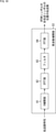
- FIG. 1 is a block diagram showing a configuration example of an embodiment of a transmission system to which the present technology is applied.
- the transmission system includes a transmission device 11, a reception device 12, and an output device 13.
- the transmission device 11 can, for example, transmit (broadcast) (transmit) a television broadcast program or the like in combination with SFN and OFDM.
- the transmission device 11 uses, for example, program contents such as image data and audio data as data to be transmitted, and performs transmission processing necessary for the data to be transmitted.
- the transmission device 11 transmits an OFDM signal as a broadcast signal obtained by performing transmission processing on the data to be transmitted via, for example, a transmission line such as a satellite line, a terrestrial wave, or a cable (wired line).
- the receiving device 12 receives the OFDM signal as a broadcasting signal transmitted from the transmitting device 11 via the transmission line, restores the content of the program included in the broadcasting signal, and supplies the content to the output device 13.
- the output device 13 has a display for displaying an image and a speaker for outputting sound (sound), displays an image as content or the like from the receiving device 12, and outputs sound.
- a plurality of the transmitting device 11, the receiving device 12, and both the transmitting device 11 and the receiving device 12 can be provided.
- SFN can be adopted.
- FIG. 2 is a block diagram showing a configuration example of the transmission device 11 of FIG.
- the transmission device 11 is, for example, a transmission device using ISDB-T, and can perform layered transmission in which the transmission band is layered in the frequency direction (hereinafter, also referred to as frequency division layered transmission).
- ISDB-T a maximum of three layers of A layer, B layer, and C layer can be transmitted.
- one channel composed of 13 segments is divided into two layers, an A layer composed of one segment and a B layer composed of 12 segments. Is being done. So-called one-segment broadcasting is performed on the A layer, and so-called 2K broadcasting is performed on the B layer.
- the transmission device 11 includes a BICM (Bit Interleaved and Coded Modulation) unit 21, a time IL (Interleave) unit 22, a layer synthesis unit 23, a frequency IL unit 24, an additional information generation unit 25, and an OFDM frame configuration unit 26. It has an IFFT (Inverse Fast Fourier Transform) unit 27, a GI (Guard Interval) addition unit 28, and a transmission unit 29.
- the data of the transmission target that the transmission device 11 originally wants to transmit in the A layer, the B layer, and the C layer for example, the data of the content of the program to be broadcast in the A layer, the B layer, and the C layer.
- Data in the A layer, data in the B layer, and data in the C layer are supplied.
- the BICM unit 21 performs FEC (Forward Error Correcton) coding processing such as LDPC (Low Density Parity Check) coding for the A layer data, the B layer data, and the C layer data, and (IQ). Mapping to the constellation and the like are performed, and the transmission symbol (position on the constellation) of the A layer to the C layer obtained as a result is supplied to the time IL unit 22.
- FEC Forward Error Correcton
- LDPC Low Density Parity Check
- the time IL unit 22 performs time interleaving of the transmission symbols of the A layer to the C layer from the BICM unit 21, and supplies the transmission symbols after the time interleaving to the layer synthesis unit 23.
- the layer synthesis unit 23 performs layered synthesis of the transmission symbols of the A layer or the C layer from the time IL unit 22, and supplies the transmission symbol after the layer composition to the frequency IL unit 24.
- the frequency IL unit 24 performs frequency interleaving of the transmission symbol from the layer synthesis unit 23, and supplies the transmission symbol after the frequency interleaving to the OFDM frame configuration unit 26.
- the additional information generation unit 25 generates additional information added in the physical layer such as a pilot signal and other ISDB-T TMCC (Transmission and Multiplexing Configuration and Control) signals and an AC (Auxiliary Channel) signal, and generates OFDM. It is supplied to the frame component 26.
- TMCC Transmission and Multiplexing Configuration and Control
- AC Advanced Channel
- the OFDM frame configuration unit 26 constitutes an OFDM frame by adding (inserting) a transmission symbol of additional information such as a pilot signal from the additional information generation unit 25 to the transmission symbol from the frequency IL unit 24, and constitutes an OFDM frame. Supply to 27.
- the IFFT unit 27 uses the OFDM frame supplied from the OFDM frame configuration unit 26 as a signal in the frequency domain, performs IFFT of the OFDM frame in a predetermined FFT size, converts it into an OFDM frame in the time domain, and adds a GI. Supply to unit 28.
- the sequence of transmission symbols for the FFT size at which IFFT is performed is called an OFDM symbol.
- the GI addition unit 28 adds an OFDM signal as a broadcast signal to each OFDM symbol constituting the OFDM frame in the time domain from the IFFT unit 27 by adding a GI having a predetermined ratio of the symbol length of the OFDM symbol. Generate and supply to the transmission unit 29.
- the transmission unit 29 performs frequency conversion of the broadcast signal from the GI addition unit 28, and transmits the OFDM signal as the broadcast signal after the frequency conversion.
- FIG. 3 is a block diagram showing a configuration example of the receiving device 12 of FIG.
- the receiving device 12 is, for example, a receiving device using ISDB-T, and can receive broadcasts by frequency division hierarchical transmission.
- the receiving device 12 has an OFDM demodulation unit 31, a frequency DIL (Deinterleave) unit 32, a layer division unit 33, a time DIL unit 34, a BICM unit 35, and an additional information decoding unit 36.
- a frequency DIL Deinterleave
- the OFDM demodulation unit 31 receives the OFDM signal transmitted from the transmission device 11.
- the OFDM demodulation unit 31 demodulates the OFDM signal and supplies the OFDM signal (OFDM symbol) obtained by the demodulation to the frequency DIL unit 32.
- the frequency DIL unit 32 performs frequency deinterleaving of the OFDM signal from the OFDM demodulation unit 31, and supplies the OFDM signal after the frequency deinterleaving to the layer division unit 33.
- the layer division unit 33 divides the OFDM signal from the frequency DIL unit 32 into layers, and supplies the OFDM signal of a predetermined layer from the A layer to the C layer to the time DIL unit 34.
- the time DIL unit 34 performs time deinterleaving of the OFDM signal from the layer dividing unit 33, and supplies the OFDM signal after the time deinterleaving to the BICM unit 35.
- the BICM unit 35 performs FEC decoding processing such as decoding of the OFDM signal and decoding of the LDPC code, and outputs the data obtained as a result to the outside.
- the additional information decoding unit 36 decodes additional information, for example, a TMCC signal from the signal in the process of demodulating the OFDM signal of the OFDM demodulation unit 31.
- the TMCC signal contains, for example, information such as a modulation method, and is supplied to a necessary block of the receiving device 12.
- FIG. 4 is a block diagram showing a configuration example of the OFDM demodulation unit 31 of FIG.
- the OFDM demodulation unit 31 includes a tuner 41, an AD (Analog / Digital) conversion unit 42, an orthogonal demodulation unit 43, an FFT unit 44, a transmission line characteristic estimation unit 45, and an equalization unit 46.
- AD Analog / Digital
- the tuner 41 selects an OFDM signal as a broadcast signal of a predetermined channel and frequency-converts it into an IF (Intermidiate Frequency) signal.
- the tuner 41 supplies the IF signal to the AD conversion unit 42.
- the AD conversion unit 42 AD-converts the IF signal from the tuner 41, and supplies the IF signal of the digital signal obtained as a result to the orthogonal demodulation unit 43.
- the orthogonal demodulation unit 43 orthogonally demodulates the IF signal from the AD conversion unit 42 using a carrier of a predetermined frequency (carrier frequency), and outputs the resulting baseband OFDM signal.
- the OFDM signal output by the orthogonal demodulation unit 43 is a signal in the time domain before the FFT calculation is performed (immediately after the transmission symbol on the IQ constellation is DIFT calculated on the transmission device 11 side). , Also referred to as an OFDM time domain signal.
- the OFDM time domain signal is a complex signal represented by a complex number including a real axis component (I (In Phase) component) and an imaginary axis component (Q (Quadrature Phase) component).
- the OFDM time domain signal is supplied from the orthogonal demodulation unit 43 to the FFT unit 44.
- the FFT unit 44 extracts the OFDM time domain signal (sample value) of the FFT section of a predetermined FFT size from the OFDM time domain signal from the orthogonal demodulation unit 43, and performs the FFT calculation.
- the FFT operation of the OFDM time domain signal obtains the data transmitted by the subcarrier, that is, the OFDM signal representing the transmission symbol on the constellation.
- the OFDM signal obtained by the FFT calculation of the OFDM time domain signal is a signal in the frequency domain, and is also hereinafter referred to as an OFDM frequency domain signal.
- the FFT unit 44 supplies the OFDM frequency domain signal obtained by the FFT calculation to the transmission line characteristic estimation unit 45 and the equalization unit 46.
- the transmission line characteristic estimation unit 45 estimates the transmission line characteristics at the positions in the frequency direction and the time direction of each transmission symbol of the OFDM signal by using the pilot signal appropriately inserted into the OFDM frequency domain signal from the FFT unit 44. Then, the transmission line characteristic estimation unit 45 supplies the transmission line characteristic (estimated value) to the equalization unit 46.
- the equalization unit 46 uses the transmission line characteristics (estimated value) from the transmission line characteristic estimation unit 45 to equalize the OFDM frequency region signal from the FFT unit 44 by, for example, zero-forcing, thereby performing OFDM. It corrects the amplitude and phase distortion that each transmission symbol of the signal receives in the channel.
- the equalization unit 46 supplies the equalized OFDM frequency domain signal to the frequency DIL unit 32.
- FIG. 5 is a diagram showing an OFDM symbol.
- OFDM Orthogonal subcarriers
- digital modulation such as PSK (Phase Shift Keying) and QAM (Quadrature Amplitude Modulation) is performed to allocate data to the amplitude and phase of each subcarrier.
- PSK Phase Shift Keying
- QAM Quadrature Amplitude Modulation
- modulation can be performed by the IFFT operation that performs the inverse Fourier transform. Further, the demodulation of the OFDM signal obtained as a result of the modulation can be performed by the FFT operation that performs the Fourier transform.
- the resistance to multipath can be improved by providing a signal section called GI.
- a pilot signal transmission symbol which is a known signal (a signal known on the receiving device 12 side) is inserted discretely in the time direction and the frequency direction, and in the receiving device, the pilot signal is inserted.
- OFDM OFDM
- data is transmitted (transmitted) in units called OFDM symbols.
- the OFDM symbol is composed of a valid symbol, which is a transmission symbol of the signal period in which IFFT is performed at the time of modulation, and a GI in which a part of the waveform in the latter half of the valid symbol is copied as it is at the beginning of the valid symbol.
- GI is provided at the beginning of the OFDM symbol to improve resistance to multipath.
- OFDM orthogonal frequency division multiplexing
- one OFDM frame is composed of 204 OFDM symbols, and the position where the pilot signal is inserted is predetermined with this OFDM frame as a unit.
- the amplitude and phase of the subcarriers of the OFDM signal obtained by performing OFDM of data by multipath or the like at the time of transmission are affected differently for each subcarrier.
- the transmitting device 11 makes the amplitude and phase of the subcarrier of the OFDM signal received from the transmitting device 11 equal to the amplitude and phase of the subcarrier of the OFDM signal transmitted by the transmitting device 11. Equalize the received OFDM signal (perform distortion correction).
- the transmission device 11 in the transmission device 11, known pilot signals (transmission symbols) having predetermined amplitudes and phases are discretely inserted into the transmission symbols constituting the OFDM symbol. Then, in the receiving device 12, the transmission line characteristic is estimated based on the amplitude and phase of the pilot signal, and the OFDM signal is equalized using the transmission line characteristic.
- FIG. 6 is a diagram showing an example of the arrangement of the pilot signal (transmission symbol) in the OFDM symbol.
- the horizontal axis represents frequency and the vertical axis represents time.
- the circles represent subcarriers of OFDM signals or transmission symbols constituting the OFDM symbols.
- the black circle represents a pilot symbol which is a transmission symbol of a pilot signal (SP (Scattered Pilot)).
- a set of transmission symbols arranged side by side in one line is one OFDM symbol.
- Pilot symbols are placed at multiple predetermined positions on the OFDM signal.
- the deviation of the placement position of the pilot symbols in the frequency direction in two adjacent OFDM symbols is expressed as Dx
- the arrangement interval of the pilot symbols arranged in the same frequency (same column) in the time direction is expressed as Dy.
- the pilot symbols are arranged every two OFDM symbols in the time direction and every twelve subcarriers in the frequency direction.
- the transmission line characteristic of the position of the pilot symbol (the position in the frequency direction and the position in the time direction) is estimated by using the pilot symbol and a known pilot signal (true value of the pilot signal). be able to.
- the transmission line characteristics at the positions of transmission symbols other than the pilot symbol are used for time-direction interpolation, time-direction interpolation, and frequency-direction interpolation. It can be estimated by doing both of.
- interpolation in the time direction is also referred to as time interpolation
- interpolation in the frequency direction is also referred to as frequency interpolation
- FIG. 7 is a diagram showing an example of estimating the transmission line characteristics of the position of the data symbol by time interpolation.
- the transmission path characteristic of the position of the data symbol in the column (frequency) of the pilot symbol is estimated by performing time interpolation using the transmission path characteristic of the position of the pilot symbol arranged in the column of the data symbol. be able to.
- the shaded circles represent the (positional) data symbols whose transmission line characteristics have been estimated by time interpolation.
- the transmission line characteristics can be obtained for each of the six transmission symbols (positions) for each OFDM symbol by time interpolation.
- the transmission line characteristics at the position of the pilot symbol and the transmission line characteristics at the position of the data symbol estimated by time interpolation using the transmission line characteristics are collectively referred to as the transmission line characteristics after time interpolation.
- FIG. 8 is a diagram showing an example of estimation of the transmission line characteristics of the position of the data symbol by frequency interpolation.
- the transmission path characteristic of the position of the data symbol of each OFDM symbol is the transmission path characteristic of the position of the pilot symbol lined up in the row of the data symbol, or the transmission path characteristic after time interpolation. Can be estimated by performing frequency interpolation using.
- a circle with a light shadow represents a (positional) data symbol whose transmission line characteristics are estimated by frequency interpolation.
- the transmission line characteristics at the positions of the data symbols for which the transmission line characteristics have not been estimated are estimated by frequency interpolation using the transmission line characteristics after time interpolation.
- the transmission line characteristics after time interpolation are the transmission paths at the positions of the transmission symbols every six in the frequency direction. It is a characteristic.
- frequency interpolation using the transmission line characteristics after such time interpolation the positions of the five transmission symbols between every six transmission symbols in the frequency direction (between the black circle and the shaded circle).
- the transmission line characteristics are estimated.
- the transmission line characteristic at the position of the pilot symbol (the part indicated by the black circle in FIG. 8) is the transmission line characteristic at the position of every 12 pilot symbols in the frequency direction.
- the positions of 11 transmission symbols between every 12 pilot symbols in the frequency direction (11 circles between black circles). (Position) transmission line characteristics are estimated.
- FIG. 9 is a block diagram showing a first configuration example of the transmission line characteristic estimation unit 45 of FIG.
- the transmission line characteristic estimation unit 45 includes a pilot extraction unit 51, a time interpolation unit 52, and a frequency interpolation unit 53.
- the OFDM frequency domain signal is supplied from the FFT unit 44 to the pilot extraction unit 51.
- the pilot extraction unit 51 extracts, for example, the pilot symbols arranged as shown in FIG. 6 from the OFDM frequency domain signal from the FFT unit 44.
- the pilot extraction unit 51 estimates the transmission line characteristics of the position of the pilot symbol using the pilot symbol extracted from the OFDM frequency domain signal and the pilot symbol of the known pilot signal, and supplies the transmission line characteristics to the time interpolation unit 52.
- the time interpolation unit 52 generates (estimates) the transmission line characteristics after time interpolation by performing time interpolation using the transmission line characteristics of the position of the pilot symbol from the pilot extraction unit 51, and supplies the transmission line characteristics to the frequency interpolation unit 53. do.
- the frequency interpolation unit 53 estimates the transmission line characteristics of the positions of all the transmission symbols of the OFDM symbols by performing frequency interpolation using the transmission line characteristics after the time interpolation from the time interpolation unit 52, and the equalization unit 46 is used. Supply.
- FIG. 10 is a block diagram showing a configuration example of the frequency interpolation unit 53 of FIG.
- the frequency interpolation unit 53 includes a 0 interpolation unit 61, an IFFT unit 62, a filter 63, and an FFT unit 64.
- the transmission line characteristics after time interpolation are supplied from the time interpolation unit 52 to the 0 interpolation unit 61.
- the 0 interpolation unit 61 interpolates a predetermined number of zeros as a new sample value between the sample values of the transmission line characteristics after the time interpolation from the time interpolation unit 52 to obtain the number of sample values.
- the transmission line characteristic after zero interpolation which is multiplied by the original predetermined number + 1 is generated and supplied to the IFFT unit 62.
- the 0 interpolation unit 61 in the OFDM symbol, zeros of the number of transmission symbols between the transmission symbols whose transmission line characteristics have been estimated, that is, the number of transmission symbols whose transmission line characteristics are estimated by frequency interpolation are interpolated. Will be done.
- the IFFT unit 62 performs IFFT of the transmission line characteristics after zero interpolation from the 0 interpolation unit 61, and supplies the IFFT unit 62 to the filter 63.
- the transmission line characteristic after zero interpolation from the 0 interpolation unit 61 is a signal in the frequency domain, and the IFFT unit 62 transmits the transmission line characteristic after zero interpolation in the frequency domain by IFFT after zero interpolation in the time domain. It is converted into a road characteristic and supplied to the filter 63.
- the filter 63 is an LPF (Low Pass Filter) that performs filtering for interpolation of the transmission line characteristics in the frequency direction, and filters the transmission line characteristics after zero interpolation from the IFFT unit 62.
- LPF Low Pass Filter
- a folding component is generated in the transmission line characteristic after zero interpolation.
- the loopback component generated in the transmission line characteristics after zero interpolation is removed, and the transmission line characteristics that have been interpolated in the frequency direction, that is, the transmission line characteristics of all the transmission symbols (positions) of the OFDM symbols are obtained. Generated.
- the transmission line characteristics at the positions of all the transmission symbols of the OFDM symbols obtained by filtering with the filter 63 are signals in the time domain, and the transmission line characteristics in the time domain are supplied from the filter 63 to the FFT unit 54.
- the FFT unit 54 converts the transmission path characteristics of the positions of all transmission symbols of the OFDM symbols in the time region from the filter 63 into the transmission path characteristics of the positions of all transmission symbols of the OFDM symbols in the frequency region by FFT, and equalizes them. Supply to unit 46.
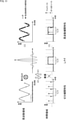
- FIG. 11 is a diagram illustrating frequency interpolation using the transmission line characteristics after time interpolation in the frequency interpolation unit 53.
- the transmission line characteristic (hereinafter, also referred to as zero interpolation characteristic) obtained as a result of this zero interpolation includes a repeating component in the time domain.
- the zero interpolation characteristic in the time domain which has 6 times the cycle of the transmission line characteristic after the time domain in the time domain as one cycle, is the transmission line characteristic after the time domain in the time domain repeated 6 times. It becomes.
- FIG. 11 shows the zero interpolation characteristics in each of the time domain and the frequency domain, and the transmission path characteristics of all the transmission symbols of the OFDM symbols obtained by filtering the zero interpolation characteristics by the filter 63.
- FIG. 11 for the sake of simplicity, it is assumed that the multipath is composed of two paths (two-wave environment). The same applies to FIG. 13, which will be described later.
- the zero interpolation characteristics with a period of Tu [seconds] are the multipath (indicated by the solid line arrow in FIG. 11) corresponding to the transmission line characteristics after the time interpolation with a period of Tu / 6 [seconds] in the time domain. It has five folding components (folding paths) (indicated by dotted arrows in FIG. 11) resulting from the interpolation of five zeros in a multipath.
- the zero interpolation characteristic with a period of Tu [seconds] is that the multipath corresponding to the transmission line characteristic after the time interpolation with a period of Tu / 6 [seconds] is repeated 6 times.
- the filter 63 which is an LPF
- the zero interpolation characteristic is filtered, the folding path is removed, and the transmission line characteristic at the position of the transmission symbol in the frequency direction is interpolated.
- the original multipath corresponding to the characteristic (hereinafter, also referred to as frequency interpolation characteristic) is extracted.
- the filter 63 is an LPF that extracts the original multipath by removing the wrapping path generated in the time domain.
- the filtering of the filter 63 is expressed as a multiplication of the zero interpolation characteristic and the window function corresponding to the pass band (time) of the LPF as the filter 63.
- the filtering of the filter 63 is a convolution of the zero interpolation characteristic and the filter coefficient of the filter 63 (impulse response in the passband of the time domain).
- the receiving device 12 may be a fixed receiver installed at home, or may be a mobile terminal such as a smartphone or an in-vehicle receiver.
- the transmission line characteristic estimation unit 45 performs time interpolation, frequency interpolation using the transmission line characteristics after time interpolation, and frequency interpolation.
- the characteristics are estimated (generated)
- the movement of the receiving device 12 increases the error of the estimated value of the frequency interpolation characteristics with respect to the current transmission line characteristics in the receiving device 12 after the movement, and the OFDM signal is appropriately equalized. It can be difficult to do.
- FIG. 12 is a block diagram showing a second configuration example of the transmission line characteristic estimation unit 45 of FIG.
- the transmission line characteristic estimation unit 45 has a pilot extraction unit 51 or a frequency interpolation unit 53. Further, the transmission line characteristic estimation unit 45 includes a frequency interpolation unit 56 and a selection unit 57.
- the transmission line characteristic estimation unit 45 of FIG. 12 has the pilot extraction unit 51 or the frequency interpolation unit 53, which is common to the case of FIG. 9, and the frequency interpolation unit 56 and the selection unit 57 are newly provided. In that respect, it differs from the case of FIG.
- the frequency interpolation unit 56 is supplied with the transmission line characteristics of the pilot symbol (position) from the pilot extraction unit 51.
- the frequency interpolation unit 56 is configured in the same manner as the frequency interpolation unit 53, estimates the frequency interpolation characteristics by performing frequency interpolation using the transmission line characteristics of the pilot symbol from the pilot extraction unit 51, and supplies the frequency interpolation characteristics to the selection unit 57. do.
- the frequency interpolation characteristic estimated by the frequency interpolation unit 53 is set to the first frequency. Also called interpolation characteristics.
- the frequency interpolation characteristic estimated by the frequency interpolation unit 56 is also referred to as a second frequency interpolation characteristic.
- the frequency interpolation unit 56 supplies the second frequency interpolation characteristic to the selection unit 57, and the frequency interpolation unit 53 also supplies the first frequency interpolation characteristic.
- the selection unit 57 selects, for example, the frequency interpolation characteristic having the smaller error among the first frequency interpolation characteristic from the frequency interpolation unit 53 and the second frequency interpolation characteristic from the frequency interpolation unit 56. It is supplied to the equalization unit 46.
- the difference between the pilot symbol in the OFDM signal after equalization using the frequency interpolation characteristic and the true value of the pilot symbol can be adopted.
- FIG. 13 is a diagram illustrating frequency interpolation using the transmission line characteristics of the pilot symbol in the frequency interpolation unit 56.
- the zero interpolation characteristic obtained as a result of these 11 zero interpolations includes a repeating component in the time domain.
- the transmission line characteristics of the pilot symbols are a series of sample values of the transmission line characteristics for each of the 12 transmission symbols (in the frequency direction).
- the effective symbol length is expressed in Tu [seconds]
- the zero interpolation characteristic in the time domain which has 12 times the cycle of the transmission line characteristic of the pilot symbol in the time domain as one cycle, is the transmission path characteristic of the pilot symbol in the time domain repeated 12 times. ..
- FIG. 13 shows the zero interpolation characteristics obtained by the interpolation of 11 zeros to the transmission line characteristics of the pilot symbol in each of the time domain and the frequency domain, and the zero interpolation characteristics obtained by filtering the zero interpolation characteristics by LPF (corresponding to the filter 63).
- LPF corresponding to the filter 63
- the zero interpolation characteristics with a period of Tu [seconds] are the multipath (indicated by the solid arrow in FIG. 13) corresponding to the transmission path characteristics of the pilot symbol with a period of Tu / 12 [seconds] and its multi. It has a folding path (indicated by a dotted arrow in FIG. 13) as 11 folding components of the path resulting from the interpolation of 11 zeros.
- the zero interpolation characteristic with a period of Tu [seconds] is that the multipath corresponding to the transmission path characteristic of the pilot symbol with a period of Tu / 12 [seconds] is repeated 12 times.
- the zero interpolation characteristic is filtered in the LPF, so that the folding path is removed and the transmission line characteristic at the position of the transmission symbol in the frequency direction is interpolated to correspond to the second frequency interpolation characteristic.
- the original multipath to be used is extracted.
- LPF filtering is expressed as a multiplication of the zero interpolation characteristic and the window function corresponding to the passband of the LPF.
- LPF filtering is a convolution of the zero interpolation characteristics and the LPF filter coefficients.
- the frequency interpolation characteristic can be estimated in a short time because the time interpolation is not performed, as compared with the case of estimating the first frequency interpolation characteristic.
- the first frequency interpolation characteristic is easily selected in the stationary environment in which the receiving device 12 is not moving, and the second frequency is easily selected in the mobile environment in which the receiving device 12 is moving. Interpolation characteristics tend to be easily selected.
- the loopback path is included in the zero interpolation characteristics obtained by zero interpolation.
- the LPF filters the zero interpolation characteristics in order to remove the wrapping path and extract the original multipath, but in order to extract the original multipath by filtering, the multipath is used.
- the maximum delay time that is, the time difference between the first pass (first reached path) and the last path (last reached path) of the multipaths must be Tu / N [seconds] or less. ..
- N represents the period (interval) of the transmission symbol in the frequency direction in which the transmission line characteristics used for frequency interpolation are obtained, and is also hereinafter referred to as the interpolation symbol period.
- the maximum delay time must be Tu / 12 [seconds] or less.
- the maximum delay time of the multipath exceeds Tu / 12 [seconds]
- the entire part from the first pass of the original multipath to the first pass does not fit within the LPF passband. Further, a part of the folded path is in the LPF pass band.
- the LPF filtering cannot extract only the original multipath, and as a result, the accuracy of the frequency interpolation characteristics deteriorates.
- the accuracy of the frequency interpolation characteristic deteriorates, the OFDM signal cannot be properly equalized, and the reception performance of the receiving device deteriorates.
- FIG. 14 is a diagram showing an example of a first frequency interpolation characteristic estimated by performing time interpolation and frequency interpolation and a second frequency interpolation characteristic estimated by performing frequency interpolation.
- the maximum delay time of multipath is within Tu / 6 [seconds], but exceeds Tu / 12 [seconds].
- the wrapping path can be removed.
- the time interpolation is performed before the frequency interpolation. Therefore, when the receiving device 12 is moving, the first frequency interpolation characteristic is estimated while the receiving device 12 is moving. As the actual transmission line characteristics change, the error of the first frequency interpolation characteristic with respect to the current transmission line characteristics becomes large, and it becomes difficult to properly equalize the OFDM signal.
- the time interpolation is not performed, so that the second frequency interpolation characteristic can be estimated in a short time. Therefore, even if the receiving device 12 is moving, it is possible to estimate the second frequency interpolation characteristic having a small error with respect to the current transmission line characteristic.
- the maximum delay time Tu / N [seconds] is large in multipath.
- a method is conceivable to prevent the wrapping path from entering within the time when the original multipath exists.
- the transmission identification signal representing the transmission identification information for identifying the transmission device 11 is injected into the OFDM signal in the transmission device 11, and the OFDM signal into which the transmission identification signal is injected is injected in the reception device 12, and a predetermined value is used.
- the reception performance of the receiving device 12 is improved by estimating the transmission line characteristics by using the correlation with the transmission identification signal of. That is, according to the present technology, in the receiving device 12, the transmission line characteristics can be estimated accurately and the OFDM signals can be appropriately equalized.
- TxID Transmitter identification
- ATSC 3.0 a transmission identification signal
- the TxID signal is a signal representing a TxID that uniquely identifies the transmitting device.
- FIG. 15 is a block diagram showing a configuration example of an ATSC 3.0 transmitter when a TxID signal is injected into an OFDM signal.
- ATSC3.0 terrestrial digital broadcasting
- ATSC3.0 terrestrial digital broadcasting
- TxID is defined in Annex N of Non-Patent Document 1, which is a standard document that defines the physical layer of ATSC 3.0.
- TxID By using TxID, it is possible to estimate the transmission line characteristics (delay profile) between the transmitting device and the receiving device.
- TxID Support for TxID is optional, and currently, there are cases where professional equipment is supported, but TV (television) receivers installed at home and TV receivers for automobiles are not supported. ..
- TxID In the transmitter corresponding to TxID, a gold series as a unique TxID that uniquely identifies the transmitter is generated, and the TxID is BPSK modulated (by TxID) to generate a TxID signal.
- the level of the TxID signal is adjusted according to the preset IL (Injection Level).
- IL is set to a value within the range of -9dB (strong) to -45dB (weak) specified in the standard.
- the level-adjusted TxID signal is injected by adding (superimposing) it to the OFDM signal (host signal) of the data to be transmitted in terrestrial digital broadcasting in ATSC3.0 in the time domain, and the TxID signal is injected.
- the OFDM signal is transmitted.
- the TxID signal is a DSBSS (direct sequence buried spread spectrum) RF (radio frequency) watermark signal that represents a gold series as a unique TxID.
- DSBSS direct sequence buried spread spectrum
- RF radio frequency
- the transmission device 101 has an input formatting unit 111, a BICM unit 112, a frame configuration / interleaving unit 113, a waveform generation unit 114, and a TxID signal generation unit. ) Section 115, an injection section 116, and a wireless interface (OVER THE AIR INTERFACE) 117.
- Data to be transmitted is supplied to the input format unit 111.
- the input format unit 111 converts the data to be transmitted into data in a predetermined format and supplies the data to the BICM unit 112.
- the BICM unit 112 performs FEC coding processing, mapping to a constellation, etc. on the data from the input format unit 111, and supplies the transmission symbol obtained as a result to the frame configuration / interleaving unit 113.
- the frame configuration / interleaving unit 113 performs time interleaving and frequency interleaving of the transmission symbol (series) from the BICM unit 112, constitutes an ATSC3.0 frame, and supplies it to the waveform generation unit 114.
- the waveform generation unit 114 generates an OFDM signal as a broadcast signal corresponding to the frame from the frame configuration / interleave unit 113 and supplies it to the injection unit 116.
- the TxID signal generation unit 115 generates a TxID signal representing the TxID that identifies the transmission device 101 and supplies it to the injection unit 116.
- the injection unit 116 injects the TxID signal from the TxID signal generation unit 115 into the OFDM signal as the broadcast signal from the waveform generation unit 114, and supplies the OFDM signal after the injection of the TxID signal to the wireless interface 117.
- the wireless interface 117 performs frequency conversion of the OFDM signal after injection of the TxID signal from the injection unit 116, and wirelessly transmits the OFDM signal after the frequency conversion.
- FIG. 16 is a diagram illustrating injection of a TxID signal into an OFDM signal at the injection unit 116.
- the frame is configured by arranging the bootstrap at the beginning and then arranging a plurality of OFDM symbols with GI at the beginning.
- preamble symbols composed of preamble transmission symbols
- preamble symbols composed of transmission symbols of data to be transmitted.
- the OFDM symbol is placed.
- the TxID signal is injected only into one of the OFDM symbols at the beginning of the frame, that is, the preamble symbol.
- one or more TxID signals are injected within the range (of time) that fits in the OFDM symbol at the beginning of the frame.
- the OFDM symbol When the FFT size when performing IFFT and FFT of an OFDM symbol is, for example, 16k (1k is 1024), the OFDM symbol has a maximum of two TxID signals representing 8191-bit TxID (8191-bit). It fits only (two TxIDs).
- the injection unit 116 when the FFT size is 16k, as shown in FIG. 16, 8191-bit (representing TxID) TxID signals are injected in a form in which only two TxID signals are repeatedly arranged.
- the TxID signal is injected in synchronization with the OFDM signal, that is, in a form in which the beginning of the preamble symbol coincides with the beginning of the first TxID signal.
- the FFT size is 8k, only one 8191-bit TxID signal is placed.
- the FFT size is 32k, only four 8191-bit TxID signals are injected in a row.
- FIG. 17 is a block diagram showing a configuration example of the TxID signal generation unit 115 of FIG.
- the TxID signal generation unit 115 has a register group 121 in the first stage, a register group 122 in the second stage, a synthesis unit 123, a BPSK modulation unit 124, and a level adjustment unit 125.
- the register group 121 of the first stage is composed of 13 registers x ⁇ 1 to x ⁇ 13 corresponding to the generation polynomial x ⁇ 13 + x ⁇ 4 + x ⁇ 3 + x + 1, and three EXOR circuits. Will be done.
- the register group 121 of the first stage generates an M sequence of 2 ⁇ 13-1 bits (period) according to the generation polynomial x ⁇ 13 + x ⁇ 4 + x ⁇ 3 + x + 1, and supplies it to the synthesis unit 123. ..
- the register group 122 in the second stage has 13 registers x corresponding to the generation polynomial x ⁇ 13 + x ⁇ 12 + x ⁇ 10 + x ⁇ 9 + x ⁇ 7 + x ⁇ 6 + x ⁇ 5 + x + 1. It consists of ⁇ 1 to x ⁇ 13 and 7 EXOR circuits.
- the register group 122 in the second stage generates a bit series according to the generation polynomial x ⁇ 13 + x ⁇ 12 + x ⁇ 10 + x ⁇ 9 + x ⁇ 7 + x ⁇ 6 + x ⁇ 5 + x + 1. It is supplied to the synthesis unit 123.
- the BPSK modulation unit 124 generates a TxID signal by BPSK modulation of the TxID from the synthesis unit 123 and supplies it to the level adjustment unit 125.
- the level adjustment unit 125 adjusts the level of the TxID signal according to the IL by multiplying the TxID signal from the BPSK modulation unit 124 by the scaling factor ⁇ corresponding to the preset IL, and the TxID signal after the level adjustment. Is supplied to the injection unit 116.
- FIG. 18 is a diagram showing initial values set in the register group 121 of the first stage and the register group 122 of the second stage.
- Tier 1 in FIG. 18 The bits shown by Tier 1 in FIG. 18 are set as initial values in the registers x ⁇ 1 to x ⁇ 13 of the register group 121 in the first stage.
- Bits t0 to t12 shown by Tier 2 in FIG. 18 are set as initial values in the registers x ⁇ 1 to x ⁇ 13 of the register group 122 in the second stage.
- the 13-bit series of bits t0 to t12 is called the txid address, and a unique value is assigned to each ATSC3.0 transmitter.
- a bit sequence is generated with the 13-bit txid address unique to the transmitting device as the initial value, and is generated by the synthesis unit 123 of the TxID signal generation unit 115 (FIG. 17).
- TxID in addition to being adopted in ATSC3.0, it is proposed to be adopted in DVB-T2.
- ATSC3.0 and DVB-T2 correspond to layered transmission layered in the time direction (hereinafter, also referred to as time-divided layered transmission), and the OFDM signal has a robust preamble symbol. Then, only in the preamble symbol at the beginning of the frame, one or more TxID signals are injected in the time domain so as to match the beginning of the preamble symbol with the beginning of the first TxID signal.
- ISDB-T the current terrestrial digital broadcasting standard in Japan, supports frequency division hierarchical transmission, and there is no robust preamble symbol in the OFDM signal (OFDM time domain signal). Similar to ISDB-T, even the advanced method (standard) being considered as the next-generation terrestrial digital broadcasting standard supports frequency-division-layer transmission, and there is no robust preamble symbol.
- frequency division layer transmission of two layers is performed as frequency division layer transmission of ISDB-T.
- the A layer is more robust than the B layer.
- the TxID signal is injected into only one of the preamble symbols, which is the OFDM symbol at the beginning of the frame.
- the frame length will be 304ms.
- the time domain signal is used for the moving receiver. It cannot be said that the transmission frequency is sufficient for estimating the transmission line characteristics with high accuracy.
- the transmission identification signal representing the transmission identification information for identifying the transmission device 11 such as the TxID signal is not only the first OFDM symbol constituting the frame of the OFDM signal but also the entire OFDM symbol. Inject into (each OFDM symbol).
- the OFDM signal in which the transmission identification signal is injected into an arbitrary OFDM symbol and a predetermined transmission identification signal are used.
- the transmission line characteristics are estimated using the correlation with. As a result, the reception performance of the receiving device 12 can be improved. That is, in the receiving device 12, the transmission line characteristics can be estimated accurately and the OFDM signals can be appropriately equalized.
- the method of injecting the TxID signal only into the preamble symbol as the first OFDM symbol constituting the frame of the OFDM signal is also called the TxID method.
- a method of injecting a transmission identification signal into all OFDM symbols constituting the frame of an OFDM signal is also referred to as a total injection method.
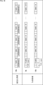
- FIG. 19 is a diagram illustrating a total injection method.
- the transmission identification signal is injected into all the OFDM symbols that make up the frame of the OFDM signal.
- the TxID signal is injected only into the preamble symbol as the first OFDM symbol constituting the frame of the OFDM signal.
- a 2 ⁇ 14-1 bit (cycle) gold series can be adopted as the transmission identification information for identifying the transmission device.
- the TxID is a 2 ⁇ 13-1 bit gold series
- the TxID signal representing such a 2 ⁇ 13-1 bit TxID is, for example, as shown in FIG. 19 when the FFT size is 8k.
- the effective symbol length Tu is planned to be 2592us, and the number of OFDM symbols constituting the frame is planned to be 112.
- the estimation of the transmission line characteristics using the TxID signal can be performed only once in 2592us. Therefore, when the receiving device is moving, the estimation accuracy of the transmission line characteristics is lowered.
- the OFDM signal with FFT size of 16k the transmission line characteristics are estimated using the transmission identification signal using the transmission identification signal injected into each of the 112 OFDM symbols. It can be performed 112 times at the maximum. Therefore, according to the full injection method, the transmission line characteristics can be estimated 112 times more frequently than the TxID method, so that the transmission line characteristics can be obtained even when the receiving device is moving. It can be estimated with high accuracy.
- the full injection method is used for OFDM signals in which the preamble symbol is placed at the beginning of the frame, such as the OFDM signal of ATSC3.0, and at the beginning of the frame, such as ISDB-T and the OFDM signal of the advanced method. It can also be applied to OFDM signals in which preamble symbols are not placed.
- the preamble symbol is robust due to the modulation method or the like, the signal deterioration due to the interference caused by the injection of the TxID signal or the transmission identification signal into the preamble symbol does not matter so much.
- the OFDM symbol corresponding to the data to be transmitted is not always robust like the preamble symbol. Therefore, signal deterioration due to interference caused by injection of the transmission identification signal into the OFDM symbol corresponding to the data to be transmitted becomes a problem. Therefore, the level (power) of the transmission identification signal injected into the OFDM symbol needs to be sufficiently low compared to the level of the OFDM symbol corresponding to the data to be transmitted.
- FIG. 20 is a diagram showing a simulation result of signal deterioration due to interference caused by injection of a transmission identification signal.
- the CNR carrier-to-noise ratio
- the CNR carrier-to-noise ratio that can demodulate the OFDM signal (necessary for demodulating the OFDM signal) is defined as the required CNR.
- FIG. 20 shows the amount of deterioration of the required CNR when the transmission identification signal is injected, as opposed to the required CNR when the transmission identification signal is not injected.
- the horizontal axis represents the required CNR when the transmission identification signal is not injected
- the vertical axis represents the IL (Injection Level) of the transmission identification signal to be injected into the OFDM signal.
- the required CNR differs depending on the modulation method and code rate.
- the modulation method is 64QAM and the coding rate is 3/4, but in this case, the required CNR without injecting the transmission identification signal is about 19 dB. Is.
- the required CNR deterioration amount is 0.2 dB or more, and it is desirable that it be about 0.1 dB or less.
- the transmission identification signal is injected with an IL whose required CNR deterioration amount when the transmission identification signal is injected is, for example, 0.1 dB or less as a threshold value.
- the required CNR without injecting the transmission identification signal is about 19 dB.
- the IL should be set to -37 dB or less in order to reduce the amount of deterioration of the required CNR to 0.1 dB or less (0.09 dB). Need to be set.
- IL is set to, for example, -37 dB.
- FIG. 21 is a block diagram showing another configuration example of the transmission device 11 of FIG.
- FIG. 21 is a block diagram showing a configuration example of the transmission device 11 that employs the full injection method.
- the transmission device 11 has a BICM unit 21 to a transmission unit 29. Further, in FIG. 21, the transmission device 11 has a transmission identification signal generation unit 201, a level adjustment unit 202, and an injection unit 203.
- the transmission device 11 of FIG. 21 is common to the case of FIG. 2 in that it has the BICM unit 21 to the transmission unit 29. However, the transmission device 11 of FIG. 21 is different from the case of FIG. 2 in that the transmission identification signal generation unit 201 to the injection unit 203 are newly provided.
- the transmission identification signal generation unit 201 generates a transmission identification signal representing the transmission identification information that identifies the transmission device 11, and supplies the transmission identification signal to the level adjustment unit 202.
- the level adjustment unit 202 adjusts the level (power) of the transmission identification signal from the transmission identification signal generation unit 201 according to the IL set in advance, and supplies the transmission identification signal after level adjustment to the injection unit 203.
- the level adjustment is performed by multiplying the transmission identification signal by the scaling factor ⁇ corresponding to IL.
- the IL sets the deterioration amount to a predetermined value, here, for example, 0.1 dB or less, depending on the deterioration amount of the required CNR due to the injection of the transmission identification signal into the OFDM signal. Is set.
- the influence of the transmission identification signal injected into the OFDM signal on the demodulation of the OFDM signal can be suppressed to an acceptable extent.
- the injection unit 203 injects the OFDM signal from the GI addition unit 28 by adding the transmission identification signal from the transmission identification signal generation unit 201, and supplies the OFDM signal after the injection of the transmission identification signal to the transmission unit 29. do.
- the injection of the transmission identification signal into the OFDM signal at the injection unit 203 is performed so that, for example, the beginning of the OFDM symbol and the beginning of the transmission identification signal coincide with each OFDM symbol of the OFDM signal.
- the transmission identification signal generation unit 201 generates a transmission identification signal representing the transmission identification information that identifies the transmission device 11, and supplies the transmission identification signal to the level adjustment unit 202.
- the level adjustment unit 202 adjusts the level of the transmission identification signal from the transmission identification signal generation unit 201, and supplies the transmission identification signal to the injection unit 203.
- a transmission identification signal is supplied to the injection unit 203 from the level adjustment unit 202, and an OFDM signal is supplied from the GI addition unit 28.
- the transmission identification signal from the transmission identification signal generation unit 201 is injected into each OFDM symbol of the OFDM signal from the GI addition unit 28 and supplied to the transmission unit 29.
- the transmission unit 29 performs frequency conversion of the OFDM signal from the injection unit 203 in which the transmission identification signal is injected into each OFDM symbol, and the OFDM signal after the frequency conversion is transmitted.
- FIG. 22 is a block diagram showing a configuration example of the transmission identification signal generation unit 201 of FIG. 21.
- the transmission identification signal generation unit 201 has a register group 221 of the first stage, a register group 222 of the second stage, a synthesis unit 223, and a BPSK modulation unit 224.
- the first-stage register group 221 contains 14 registers x ⁇ 1 to x ⁇ 14 corresponding to the generated polynomial x ⁇ 14 + x ⁇ 5 + x ⁇ 4 + x ⁇ 2 + x, and four EXOR circuits. Consists of.
- the register group 221 of the first stage generates an M sequence of 2 ⁇ 14-1 bits (period) according to the generation polynomial x ⁇ 14 + x ⁇ 5 + x ⁇ 4 + x ⁇ 2 + x, and causes the synthesis unit 223 to generate an M sequence. Supply.
- the register group 222 in the second stage has 14 registers x ⁇ 1 to x ⁇ 14 corresponding to the generated polynomial x ⁇ 14 + x ⁇ 11 + x ⁇ 10 + x ⁇ 7 + x ⁇ 6 + x ⁇ 5 + x. , And 6 EXOR circuits.
- the register group 222 in the second stage generates a bit sequence according to the generation polynomial x ⁇ 14 + x ⁇ 11 + x ⁇ 10 + x ⁇ 7 + x ⁇ 6 + x ⁇ 5 + x and supplies it to the synthesis unit 223. ..
- the generated polynomial that generates a series in the register group 221 of the first stage and the register group 222 of the second stage is not limited to the above-mentioned generated polynomial.
- the BPSK modulation unit 224 generates a transmission identification signal by BPSK modulation of the transmission identification information from the synthesis unit 223 and supplies it to the level adjustment unit 202 (FIG. 21).
- FIG. 23 is a diagram showing initial values set in the register group 221 of the first stage and the register group 222 of the second stage.
- Tier 1 in FIG. 23 The bits shown by Tier 1 in FIG. 23 are set as initial values in the registers x ⁇ 1 to x ⁇ 14 of the register group 221 in the first stage.
- Bits t1 to t14 shown by Tier 2 in FIG. 23 are set as initial values in the registers x ⁇ 1 to x ⁇ 14 of the register group 222 in the second stage.
- the 14-bit sequence of bits t1 to t14 is called the transmitter address.
- the transmitter address a unique value is assigned to each transmitter that adopts the full injection method.
- a bit sequence is generated with the 14-bit transmitter address unique to the transmitter as the initial value, and is generated by the synthesizer 123 of the transmission identification signal generator 201 (FIG. 22).
- the number of bits of the transmitter address can be set, for example, according to the total number NTx of the transmitters 11 that adopt the total injection method in the country that adopts the total injection method.
- the number of bits of the transmitter address can be set to any integer value among the integer values of log 2 NTx or more, for example, the smallest integer value. In this case, all transmitters can be assigned a unique value as the transmitter address.
- the ISDB-T transmitter (broadcasting station) is about 12000, so a transmitter address of 14 bits or more is adopted. By doing so, a unique value can be assigned to each ISDB-T transmitter as the transmitter address.
- the generation polynomial that generates a series in the register group 221 of the first stage and the register group 222 of the second stage depending on the number of bits of the transmitter address, and the register group 221 of the first stage and the second stage.
- the configuration of the register group 222 of the above is different.
- the transmission identification signal can be repeatedly injected within the range within the OFDM symbol and the length (time) of the OFDM symbol.
- the OFDM symbol has only one 16383-bit transmission identification signal (representing transmission identification information) (one of the 16383-bit transmission identification information). It fits.
- the OFDM symbol can accommodate up to two 16383-bit transmission identification signals.
- the injection unit 203 when the FFT size is 32k, 16383-bit transmission identification signals can be injected into each OFDM symbol in a form in which only two are repeatedly arranged.
- 8k FFT size is planned, and in Mode 3 of ISDB-T, 8k FFT size is defined.
- the FFT size is 8k, one OFDM symbol does not fit a 16383-bit transmission identification signal.
- the injection unit 203 is in the unit of the number of OFDM symbols in which one transmission identification signal fits according to the length of the OFDM symbol and the transmission identification signal. , One transmission identification signal can be injected over such a number of OFDM symbols.
- the injection unit 203 can repeat the injection of 16383-bit transmission identification signals over the two OFDM symbols in units of two OFDM symbols.
- the transmission identification signal is injected into all the OFDM symbols constituting the frame. Can be done.
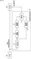
- FIG. 24 is a block diagram showing another configuration example of the OFDM demodulation unit 31 of FIG.
- FIG. 24 is a block diagram showing a configuration example of the OFDM demodulation unit 31 of the receiving device 12 (FIG. 2) that employs the full injection method.
- the OFDM demodulation unit 31 has a tuner 41 or an equalization unit 46. Further, in FIG. 31, the OFDM demodulation unit 31 has a transmission line characteristic estimation unit 301 and an acquisition unit 302.
- the OFDM demodulation unit 31 of FIG. 24 is common to the case of FIG. 4 in that it has the tuner 41 to the equalization unit 46.
- the OFDM demodulation unit 31 of FIG. 24 is different from the case of FIG. 4 in that the transmission line characteristic estimation unit 301 and the acquisition unit 302 are newly provided.
- An OFDM time domain signal is supplied from the orthogonal demodulation unit 43 to the transmission line characteristic estimation unit 301.
- the tuner 41 receives an OFDM signal from a transmission device that employs a full injection method, that is, an OFDM signal in which a transmission identification signal is injected into each OFDM symbol, as in the transmission device 11 of FIG. Receive. Therefore, the OFDM time domain signal supplied from the orthogonal demodulation unit 43 to the transmission line characteristic estimation unit 301 is an OFDM signal in which a transmission identification signal is injected into each OFDM symbol.
- the transmission line characteristic estimation unit 301 uses the OFDM time region signal from the orthogonal demodulation unit 43, and estimates and acquires the transmission line characteristics according to the transmission identification signal injected into each OFDM symbol of the OFDM time region signal. Supply to unit 302.
- the transmission line characteristic estimated by the transmission line characteristic estimation unit 301 according to the transmission identification signal is also referred to as an identification transmission line characteristic.
- the transmission line characteristic estimated by the transmission line characteristic estimation unit 45 using the pilot symbol is also referred to as a pilot transmission line characteristic.
- the transmission line characteristic estimation unit 301 supplies the identification transmission line characteristics to the acquisition unit 302, and the transmission line characteristic estimation unit 45 supplies the pilot transmission line characteristics.
- the acquisition unit 302 uses the identification transmission line characteristics from the transmission line characteristic estimation unit 301 and the pilot transmission line characteristics from the transmission line characteristic estimation unit 45, and uses the transmission line characteristics (transmission line characteristics) used for equalization in the equalization unit 46. Hereinafter, it is also referred to as an equalization transmission line characteristic) and is supplied to the equalization unit 46.
- the acquisition unit 302 selects one of the identification transmission line characteristics from the transmission line characteristic estimation unit 301 and the pilot transmission line characteristics from the transmission line characteristic estimation unit 45 as the equalization transmission line characteristics. Therefore, the transmission line characteristics for equalization can be acquired.
- the one with the smaller error among the identification transmission line characteristics and the pilot transmission line characteristics can be selected as the equalization transmission line characteristics.
- the error of the identification transmission line characteristic and the pilot transmission line characteristic for example, the pilot symbol in the OFDM signal after equalization using the identification transmission line characteristic and the pilot transmission line characteristic, and the true value of the pilot symbol. The difference between the two can be adopted.
- one of the identification transmission line characteristic and the pilot transmission line characteristic can be selected as the equalization transmission line characteristic according to the moving state of the receiving device 12. For example, when the receiving device 12 is moving at a speed equal to or higher than a predetermined speed, the identification transmission line characteristic can be selected as the equalization transmission line characteristic. If the receiving device 12 is not moving faster than a predetermined speed and can be regarded as (almost) stationary, the pilot transmission line characteristic is selected as the equalization transmission line characteristic. be able to.
- the acquisition unit 302 can acquire the processed pilot transmission line characteristics as the equalization transmission line characteristics by processing the pilot transmission line characteristics according to the identification transmission line characteristics, for example.
- the acquisition unit 302 can detect the return path included in the pilot transmission line characteristics by comparing the identification transmission line characteristics and the pilot transmission line characteristics. Then, the acquisition unit 302 performs processing to remove the folded path by filtering the pilot transmission line characteristics with a filter, and acquires the pilot transmission line characteristics after the processing as the equalization transmission line characteristics. can.
- the identification transmission line characteristic can always be used as the equalization transmission line characteristic.
- the OFDM demodulation unit 31 can be configured without providing the transmission line characteristic estimation unit 45 and the acquisition unit 302.
- FIG. 25 is a block diagram showing a configuration example of the transmission line characteristic estimation unit 301 of FIG. 24.
- the transmission line characteristic estimation unit 301 has a transmission identification signal generation unit 311, a correlation calculation unit 312, an estimation unit 313, and an FFT unit 314.
- the transmission identification signal generation unit 311 is configured in the same manner as the transmission identification signal generation unit 201 of FIG.
- the transmission identification signal generation unit 311 sets the second stage of each of the transmission device addresses of one or more transmission devices 11 constituting the transmission system of FIG. 1, for example, all or a part of the transmission devices 11 constituting the transmission system of FIG. It is set as an initial value of the register group 222 of the above, and a transmission identification signal for identifying each of one or more transmission devices 11 is generated.
- the transmission identification signal generation unit 311 supplies a transmission identification signal that identifies each of the transmission devices 11 (one or more) to the correlation calculation unit 312.
- the transmission device 11 (hereinafter, also referred to as the target transmission device 11) to be generated by the transmission identification signal generation unit 311) all of the transmission devices 11 constituting the transmission system of FIG. 1 may be set. can. Further, as the target transmitting device 11, it is possible to set a transmitting device 11 that is transmitting an OFDM signal that can be received by the receiving device 12, for example, a transmitting device 11 within a predetermined distance from the receiving device 12. can.
- the target transmission device 11 can be appropriately set.
- the transmission identification signal of the target transmission device 11 is supplied from the transmission identification signal generation unit 311 to the correlation calculation unit 312, and the OFDM time domain signal is supplied from the orthogonal demodulation unit 43.
- the transmission identification signal of the transmission device 11 that has transmitted the OFDM signal as the corresponding broadcast signal is injected into each OFDM symbol of the OFDM time domain signal supplied from the orthogonal demodulation unit 43 to the correlation calculation unit 312.
- the correlation calculation unit 312 correlates the transmission identification signal of the target transmission device 11 from the transmission identification signal generation unit 311 with the OFDM time domain signal from the orthogonal demodulation unit 43, for example, SWC (sliding). window correlation) is calculated.
- SWC sliding time domain signal
- the SWC is a correlation between the OFDM time domain signal in the window, which is calculated while shifting the window (function), and the transmission identification signal of the target transmission device 11.
- the correlation calculation unit 312 supplies the SWC calculated for each transmission identification signal of the target transmission device 11 from the transmission identification signal generation unit 311 to the estimation unit 313.
- the estimation unit 313 estimates the (identification) transmission line characteristics using the SWC for each transmission identification signal of the target transmission device 11 from the correlation calculation unit 312.
- the estimation unit 313 estimates the transmission line characteristics between the target transmission device 11 and the reception device 12 by using the SWC for the transmission identification signal of the individual target transmission device 11. Therefore, the estimation unit 313 can estimate the transmission line characteristics between the target transmission device 11 and the reception device 12.
- the estimation unit 313 estimates the final transmission line characteristics (between the reception device 12 and the reception device 12) for each target transmission device 11.
- the estimation unit 313 estimates the final transmission line characteristics by synthesizing all or part of the transmission line characteristics for each target transmission device 11.
- the transmission line characteristics to be synthesized include, for example, the transmission line characteristics whose path level (power) is equal to or higher than the threshold value, or the path level as the receiving device 12 moves. It is possible to adopt a transmission line characteristic or the like that is predicted to change above the threshold value.
- the transmission identification signal is injected into each OFDM symbol, so that the estimation unit 313 can estimate the transmission line characteristics with the frequency of the OFDM symbols. Therefore, even if the receiving device 12 is moving, the transmission line characteristics can be estimated with high accuracy.
- the transmission line characteristics are estimated by the estimation unit 313 using SWC, it is possible to estimate the transmission line characteristics with high accuracy without being affected by the folding path.
- the estimation unit 313 supplies the final transmission line characteristics to the FFT unit 314 as identification transmission line characteristics.
- the FFT unit 314 converts the identification transmission line characteristics from the estimation unit 313 from the information in the time domain to the information in the frequency domain by the FFT and supplies the information to the acquisition unit 302.
- FIG. 26 is a block diagram showing a configuration example of an embodiment of a computer in which a program for executing the above-mentioned series of processes is installed.
- the program can be recorded in advance on the hard disk 905 or ROM 903 as a recording medium built in the computer.
- the program can be stored (recorded) in the removable recording medium 911 driven by the drive 909.
- a removable recording medium 911 can be provided as so-called package software.
- examples of the removable recording medium 911 include a flexible disc, a CD-ROM (Compact Disc Read Only Memory), a MO (Magneto Optical) disc, a DVD (Digital Versatile Disc), a magnetic disc, and a semiconductor memory.
- the program can be downloaded to the computer via a communication network or a broadcasting network and installed on the built-in hard disk 905. That is, for example, the program transfers wirelessly from a download site to a computer via an artificial satellite for digital satellite broadcasting, or transfers to a computer by wire via a network such as LAN (Local Area Network) or the Internet. be able to.
- LAN Local Area Network
- the computer has a built-in CPU (Central Processing Unit) 902, and the input / output interface 910 is connected to the CPU 902 via the bus 901.
- CPU Central Processing Unit
- the CPU 902 executes a program stored in the ROM (Read Only Memory) 903 accordingly. .. Alternatively, the CPU 902 loads the program stored in the hard disk 905 into the RAM (Random Access Memory) 904 and executes it.
- ROM Read Only Memory
- the CPU 902 performs the processing according to the above-mentioned flowchart or the processing performed according to the above-mentioned block diagram configuration. Then, the CPU 902 outputs the processing result from the output unit 906, transmits it from the communication unit 908, and records it on the hard disk 905, if necessary, via, for example, the input / output interface 910.
- the input unit 907 is composed of a keyboard, a mouse, a microphone, and the like. Further, the output unit 906 is composed of an LCD (Liquid Crystal Display), a speaker, or the like.
- LCD Liquid Crystal Display
- the processes performed by the computer according to the program do not necessarily have to be performed in chronological order in the order described as the flowchart. That is, the processing performed by the computer according to the program includes processing executed in parallel or individually (for example, processing by parallel processing or processing by an object).
- the program may be processed by one computer (processor) or may be distributed processed by a plurality of computers. Further, the program may be transferred to a distant computer and executed.
- the system means a set of a plurality of components (devices, modules (parts), etc.), and it does not matter whether all the components are in the same housing. Therefore, a plurality of devices housed in separate housings and connected via a network, and a device in which a plurality of modules are housed in one housing are both systems. ..
- this technology can take a cloud computing configuration in which one function is shared by multiple devices via a network and processed jointly.
- each step described in the above flowchart can be executed by one device or can be shared and executed by a plurality of devices.
- the plurality of processes included in the one step can be executed by one device or shared by a plurality of devices.
- a transmission identification signal generator that generates a transmission identification signal that represents transmission identification information that identifies a transmitter that transmits an OFDM (Orthogonal Frequency Division Multiplexing) signal.
- a transmission device comprising an injection unit that injects the transmission identification signal at a lower level than the OFDM signal corresponding to the data to be transmitted into all the OFDM symbols of the OFDM signal.
- the transmission device according to ⁇ 1> which performs layered transmission in which the transmission band is layered in the frequency direction.
- the transmission identification information is a gold series generated by using a transmission device address having a unique value for each transmission device.
- the transmitting device according to ⁇ 1> or ⁇ 2>, wherein the number of bits of the transmitting device address is set according to the total number of transmitting devices that transmit the OFDM signal.
- the transmission device according to ⁇ 3>, wherein the number of bits of the transmission device address is set to a minimum integer value of log 2 NTx or more according to the total number of transmission devices NTx.
- the transmission identification information is a gold series generated by using a transmission device address having a unique value for each transmission device.
- the transmitter according to ⁇ 1> or ⁇ 2>, wherein the number of bits of the transmitter address is 14 bits or more.
- the injection unit injects the transmission identification signal for the case where the transmission identification signal of the required CNR (carrier-to-noise ratio) required for demodulation of the OFDM signal is not injected in the receiving device that receives the OFDM signal.
- the transmission device according to any one of ⁇ 1> to ⁇ 5>, which injects the transmission identification signal at a level at which the amount of deterioration is equal to or less than a threshold value.
- the injection unit injects the transmission identification signal over the number of OFDM symbols in which one transmission identification signal fits, depending on the length of the OFDM symbol and the transmission identification signal ⁇ 1> to ⁇ 6>.
- the transmitter according to any of the above.
- the transmission device according to any one of ⁇ 1> to ⁇ 8>, wherein the OFDM signal is an OFDM signal in which a preamble symbol, which is an OFDM symbol composed of a preamble transmission symbol, does not exist.
- a transmission method comprising injecting the transmission identification signal at a lower level than the OFDM signal corresponding to the data to be transmitted into all the OFDM symbols of the OFDM signal.
- the OFDM signal after injection of the transmission identification signal obtained by injecting the transmission identification signal at a lower level than the OFDM signal corresponding to the data to be transmitted into all the OFDM symbols of the OFDM signal.
- a receiver equipped with a demodulation unit that demodulates.
- the receiving device wherein the demodulation unit uses the OFDM signal and estimates transmission line characteristics according to the transmission identification signal injected into the OFDM symbol of the OFDM signal.
- the OFDM signal includes a pilot symbol which is a transmission symbol of the pilot signal.
- the demodulation unit Using the pilot symbol, the transmission line characteristics are estimated and Equalization of the OFDM signal by using the identification transmission line characteristic which is the transmission line characteristic estimated according to the transmission identification signal and the pilot transmission line characteristic which is the transmission line characteristic estimated by using the pilot symbol.
- the receiver which acquires the equalization transmission line characteristic which is the transmission line characteristic used in the above.
- the demodulation unit acquires the equalization transmission line characteristics by selecting one of the identification transmission line characteristics and the pilot transmission line characteristics as the equalization transmission line characteristics ⁇ 13>.
- the receiver described in. ⁇ 15> The receiving device according to ⁇ 14>, wherein the demodulation unit selects the smaller error of the identification transmission line characteristic and the pilot transmission line characteristic as the equalization transmission line characteristic.
- ⁇ 16> The receiving device according to ⁇ 14>, wherein the demodulation unit selects one of the identification transmission line characteristic and the pilot transmission line characteristic as the equalization transmission line characteristic according to the moving state of the receiving device. ..
- the demodulation unit describes the pilot transmission line characteristics after processing by processing the pilot transmission line characteristics according to the identification transmission line characteristics, and acquires the processed pilot transmission line characteristics as the equalization transmission line characteristics.
- Receiver. ⁇ 18>
- the demodulation unit The transmission identification signal of each of the target transmission devices, which is one or more transmission devices to be generated of the transmission identification signal, is generated. For each of the target transmission devices, the correlation between the transmission identification signal and the OFDM signal is calculated.
- the receiving device according to any one of ⁇ 12> to ⁇ 17>, which estimates the transmission line characteristics for each target transmitting device using the correlation.
- the OFDM signal is an OFDM signal in which a preamble symbol, which is an OFDM symbol composed of a preamble transmission symbol, does not exist.
- the OFDM signal after injection of the transmission identification signal obtained by injecting the transmission identification signal at a lower level than the OFDM signal corresponding to the data to be transmitted into all the OFDM symbols of the OFDM signal.
- Receiving method including demodulation.
- Transmitter 12 Receiver, 13 Output device, 21 BICM section, 22 Time IL section, 23 Hierarchical synthesis section, 24 Frequency IL section, 25 Additional information generation section, 26 OFDM frame configuration section, 27 IFFT section, 28 GI addition Unit, 29 transmission unit, 31 OFDM demodulation unit, 32 frequency DIL unit, 33 layer division unit, 34 time DIL unit, 35 BICM unit, 36 additional information decoding unit, 41 tuner, 42 AD conversion unit, 43 orthogonal demodulation unit, 44 FFT section, 45 transmission line characteristic estimation section, 46 equalization section, 51 pilot extraction section, 52 time interpolation section, 53,56 frequency interpolation section, 57 selection section, 61.0 interpolation section, 62 IFFT section, 63 filter, 64 FFT.
Abstract
Description
OFDM(Orthogonal Frequency Division Multiplexing)信号を送信する送信装置を識別する送信識別情報を表す送信識別信号を生成する送信識別信号生成部と、
送信対象のデータに対応する前記OFDM信号より低レベルの前記送信識別信号を、前記OFDM信号のOFDMシンボルのすべてに注入する注入部と
を備える送信装置。
<2>
伝送帯域を周波数方向に階層分けした階層伝送を行う
<1>に記載の送信装置。
<3>
前記送信識別情報は、送信装置ごとに固有の値の送信装置アドレスを用いて生成されるゴールド系列であり、
前記送信装置アドレスのビット数は、前記OFDM信号を送信する送信装置の総数に応じて設定される
<1>又は<2>に記載の送信装置。
<4>
前記送信装置アドレスのビット数は、前記送信装置の総数NTxに応じて、log2NTx以上の最小の整数値に設定される
<3>に記載の送信装置。
<5>
前記送信識別情報は、送信装置ごとに固有の値の送信装置アドレスを用いて生成されるゴールド系列であり、
前記送信装置アドレスのビット数は、14ビット以上である
<1>又は<2>に記載の送信装置。
<6>
前記注入部は、前記OFDM信号を受信する受信装置において前記OFDM信号の復調に必要な所要CNR(carrier-to-noise ratio)の、前記送信識別信号を注入しない場合に対する、前記送信識別信号を注入した場合の劣化量が閾値以下となるレベルの前記送信識別信号を注入する
<1>ないし<5>のいずれかに記載の送信装置。
<7>
前記注入部は、前記送信識別信号を、前記OFDMシンボル及び前記送信識別信号の長さに応じて、前記OFDMシンボルに収まる範囲内で繰り返し注入する
<1>ないし<6>のいずれかに記載の送信装置。
<8>
前記注入部は、前記OFDMシンボル及び前記送信識別信号の長さに応じて、1つの前記送信識別信号が収まる数のOFDMシンボルに亘って、前記送信識別信号を注入する
<1>ないし<6>のいずれかに記載の送信装置。
<9>
前記OFDM信号は、プリアンブルの伝送シンボルで構成されるOFDMシンボルであるプリアンブルシンボルが存在しないOFDM信号である
<1>ないし<8>のいずれかに記載の送信装置。
<10>
OFDM(Orthogonal Frequency Division Multiplexing)信号を送信する送信装置を識別する送信識別情報を表す送信識別信号を生成することと、
送信対象のデータに対応する前記OFDM信号より低レベルの前記送信識別信号を、前記OFDM信号のOFDMシンボルのすべてに注入することと
を含む送信方法。
<11>
OFDM(Orthogonal Frequency Division Multiplexing)信号を送信する送信装置を識別する送信識別情報を表す送信識別信号を生成することと、
送信対象のデータに対応する前記OFDM信号より低レベルの前記送信識別信号を、前記OFDM信号のOFDMシンボルのすべてに注入することと
により得られた、前記送信識別信号の注入後の前記OFDM信号を復調する復調部を備える
受信装置。
<12>
前記復調部は、前記OFDM信号を用い、前記OFDM信号の前記OFDMシンボルに注入されている前記送信識別信号に応じて、伝送路特性を推定する
<11>に記載の受信装置。
<13>
前記OFDM信号は、パイロット信号の伝送シンボルであるパイロットシンボルを含み、
前記復調部は、
前記パイロットシンボルを用いて、伝送路特性を推定し、
前記送信識別信号に応じて推定された伝送路特性である識別伝送路特性と、前記パイロットシンボルを用いて推定された伝送路特性であるパイロット伝送路特性とを用いて、前記OFDM信号の等化に用いる伝送路特性である等化用伝送路特性を取得する
<12>に記載の受信装置。
<14>
前記復調部は、前記識別伝送路特性、及び、前記パイロット伝送路特性のうちの一方を、前記等化用伝送路特性として選択することにより、前記等化用伝送路特性を取得する
<13>に記載の受信装置。
<15>
前記復調部は、前記識別伝送路特性、及び、前記パイロット伝送路特性のうちの、誤差が小さい方を、前記等化用伝送路特性として選択する
<14>に記載の受信装置。
<16>
前記復調部は、前記受信装置の移動状態に応じて、前記識別伝送路特性及び前記パイロット伝送路特性のうちの一方を、前記等化用伝送路特性として選択する
<14>に記載の受信装置。
<17>
前記復調部は、前記パイロット伝送路特性を、前記識別伝送路特性に応じて加工することにより、加工後のパイロット伝送路特性を、前記等化用伝送路特性として取得する
<13>に記載の受信装置。
<18>
前記復調部は、
前記送信識別信号の生成の対象とする1以上の送信装置である対象送信装置それぞれの前記送信識別信号を生成し、
前記対象送信装置それぞれについて、前記送信識別信号と前記OFDM信号との相関を演算し、
前記相関を用いて、前記対象送信装置ごとの前記伝送路特性を推定する
<12>ないし<17>のいずれかに記載の受信装置。
<19>
前記OFDM信号は、プリアンブルの伝送シンボルで構成されるOFDMシンボルであるプリアンブルシンボルが存在しないOFDM信号である
<11>に記載の受信装置。
<20>
OFDM(Orthogonal Frequency Division Multiplexing)信号を送信する送信装置を識別する送信識別情報を表す送信識別信号を生成することと、
送信対象のデータに対応する前記OFDM信号より低レベルの前記送信識別信号を、前記OFDM信号のOFDMシンボルのすべてに注入することと
により得られた、前記送信識別信号の注入後の前記OFDM信号を復調することを含む
受信方法。 <1>
A transmission identification signal generator that generates a transmission identification signal that represents transmission identification information that identifies a transmitter that transmits an OFDM (Orthogonal Frequency Division Multiplexing) signal.
A transmission device comprising an injection unit that injects the transmission identification signal at a lower level than the OFDM signal corresponding to the data to be transmitted into all the OFDM symbols of the OFDM signal.
<2>
The transmission device according to <1>, which performs layered transmission in which the transmission band is layered in the frequency direction.
<3>
The transmission identification information is a gold series generated by using a transmission device address having a unique value for each transmission device.
The transmitting device according to <1> or <2>, wherein the number of bits of the transmitting device address is set according to the total number of transmitting devices that transmit the OFDM signal.
<4>
The transmission device according to <3>, wherein the number of bits of the transmission device address is set to a minimum integer value of log 2 NTx or more according to the total number of transmission devices NTx.
<5>
The transmission identification information is a gold series generated by using a transmission device address having a unique value for each transmission device.
The transmitter according to <1> or <2>, wherein the number of bits of the transmitter address is 14 bits or more.
<6>
The injection unit injects the transmission identification signal for the case where the transmission identification signal of the required CNR (carrier-to-noise ratio) required for demodulation of the OFDM signal is not injected in the receiving device that receives the OFDM signal. The transmission device according to any one of <1> to <5>, which injects the transmission identification signal at a level at which the amount of deterioration is equal to or less than a threshold value.
<7>
The injection unit according to any one of <1> to <6>, in which the transmission identification signal is repeatedly injected within a range within the OFDM symbol and the length of the transmission identification signal. Transmitter.
<8>
The injection unit injects the transmission identification signal over the number of OFDM symbols in which one transmission identification signal fits, depending on the length of the OFDM symbol and the transmission identification signal <1> to <6>. The transmitter according to any of the above.
<9>
The transmission device according to any one of <1> to <8>, wherein the OFDM signal is an OFDM signal in which a preamble symbol, which is an OFDM symbol composed of a preamble transmission symbol, does not exist.
<10>
Generating a transmission identification signal that represents transmission identification information that identifies a transmitter that transmits an OFDM (Orthogonal Frequency Division Multiplexing) signal.
A transmission method comprising injecting the transmission identification signal at a lower level than the OFDM signal corresponding to the data to be transmitted into all the OFDM symbols of the OFDM signal.
<11>
Generating a transmission identification signal that represents transmission identification information that identifies a transmitter that transmits an OFDM (Orthogonal Frequency Division Multiplexing) signal.
The OFDM signal after injection of the transmission identification signal obtained by injecting the transmission identification signal at a lower level than the OFDM signal corresponding to the data to be transmitted into all the OFDM symbols of the OFDM signal. A receiver equipped with a demodulation unit that demodulates.
<12>
The receiving device according to <11>, wherein the demodulation unit uses the OFDM signal and estimates transmission line characteristics according to the transmission identification signal injected into the OFDM symbol of the OFDM signal.
<13>
The OFDM signal includes a pilot symbol which is a transmission symbol of the pilot signal.
The demodulation unit
Using the pilot symbol, the transmission line characteristics are estimated and
Equalization of the OFDM signal by using the identification transmission line characteristic which is the transmission line characteristic estimated according to the transmission identification signal and the pilot transmission line characteristic which is the transmission line characteristic estimated by using the pilot symbol. The receiver according to <12>, which acquires the equalization transmission line characteristic which is the transmission line characteristic used in the above.
<14>
The demodulation unit acquires the equalization transmission line characteristics by selecting one of the identification transmission line characteristics and the pilot transmission line characteristics as the equalization transmission line characteristics <13>. The receiver described in.
<15>
The receiving device according to <14>, wherein the demodulation unit selects the smaller error of the identification transmission line characteristic and the pilot transmission line characteristic as the equalization transmission line characteristic.
<16>
The receiving device according to <14>, wherein the demodulation unit selects one of the identification transmission line characteristic and the pilot transmission line characteristic as the equalization transmission line characteristic according to the moving state of the receiving device. ..
<17>
The demodulation unit describes the pilot transmission line characteristics after processing by processing the pilot transmission line characteristics according to the identification transmission line characteristics, and acquires the processed pilot transmission line characteristics as the equalization transmission line characteristics. Receiver.
<18>
The demodulation unit
The transmission identification signal of each of the target transmission devices, which is one or more transmission devices to be generated of the transmission identification signal, is generated.
For each of the target transmission devices, the correlation between the transmission identification signal and the OFDM signal is calculated.
The receiving device according to any one of <12> to <17>, which estimates the transmission line characteristics for each target transmitting device using the correlation.
<19>
The receiving device according to <11>, wherein the OFDM signal is an OFDM signal in which a preamble symbol, which is an OFDM symbol composed of a preamble transmission symbol, does not exist.
<20>
Generating a transmission identification signal that represents transmission identification information that identifies a transmitter that transmits an OFDM (Orthogonal Frequency Division Multiplexing) signal.
The OFDM signal after injection of the transmission identification signal obtained by injecting the transmission identification signal at a lower level than the OFDM signal corresponding to the data to be transmitted into all the OFDM symbols of the OFDM signal. Receiving method including demodulation.
Claims (20)
- OFDM(Orthogonal Frequency Division Multiplexing)信号を送信する送信装置を識別する送信識別情報を表す送信識別信号を生成する送信識別信号生成部と、
送信対象のデータに対応する前記OFDM信号より低レベルの前記送信識別信号を、前記OFDM信号のOFDMシンボルのすべてに注入する注入部と
を備える送信装置。 A transmission identification signal generator that generates a transmission identification signal that represents transmission identification information that identifies a transmitter that transmits an OFDM (Orthogonal Frequency Division Multiplexing) signal.
A transmission device comprising an injection unit that injects the transmission identification signal at a lower level than the OFDM signal corresponding to the data to be transmitted into all the OFDM symbols of the OFDM signal. - 伝送帯域を周波数方向に階層分けした階層伝送を行う
請求項1に記載の送信装置。 The transmission device according to claim 1, wherein the transmission band is layered in the frequency direction for layered transmission. - 前記送信識別情報は、送信装置ごとに固有の値の送信装置アドレスを用いて生成されるゴールド系列であり、
前記送信装置アドレスのビット数は、前記OFDM信号を送信する送信装置の総数に応じて設定される
請求項1に記載の送信装置。 The transmission identification information is a gold series generated by using a transmission device address having a unique value for each transmission device.
The transmission device according to claim 1, wherein the number of bits of the transmission device address is set according to the total number of transmission devices that transmit the OFDM signal. - 前記送信装置アドレスのビット数は、前記送信装置の総数NTxに応じて、log2NTx以上の最小の整数値に設定される
請求項3に記載の送信装置。 The transmitter according to claim 3, wherein the number of bits of the transmitter address is set to a minimum integer value of log 2 NTx or more according to the total number of NTx of the transmitters. - 前記送信識別情報は、送信装置ごとに固有の値の送信装置アドレスを用いて生成されるゴールド系列であり、
前記送信装置アドレスのビット数は、14ビット以上である
請求項1に記載の送信装置。 The transmission identification information is a gold series generated by using a transmission device address having a unique value for each transmission device.
The transmitter according to claim 1, wherein the number of bits of the transmitter address is 14 bits or more. - 前記注入部は、前記OFDM信号を受信する受信装置において前記OFDM信号の復調に必要な所要CNR(carrier-to-noise ratio)の、前記送信識別信号を注入しない場合に対する、前記送信識別信号を注入した場合の劣化量が閾値以下となるレベルの前記送信識別信号を注入する
請求項1に記載の送信装置。 The injection unit injects the transmission identification signal for the case where the transmission identification signal of the required CNR (carrier-to-noise ratio) required for demodulation of the OFDM signal is not injected in the receiving device that receives the OFDM signal. The transmission device according to claim 1, wherein the transmission identification signal at a level at which the deterioration amount is equal to or less than a threshold value is injected. - 前記注入部は、前記送信識別信号を、前記OFDMシンボル及び前記送信識別信号の長さに応じて、前記OFDMシンボルに収まる範囲内で繰り返し注入する
請求項1に記載の送信装置。 The transmission device according to claim 1, wherein the injection unit repeatedly injects the transmission identification signal within a range within the OFDM symbol according to the length of the OFDM symbol and the transmission identification signal. - 前記注入部は、前記OFDMシンボル及び前記送信識別信号の長さに応じて、1つの前記送信識別信号が収まる数のOFDMシンボルに亘って、前記送信識別信号を注入する
請求項1に記載の送信装置。 The transmission according to claim 1, wherein the injection unit injects the transmission identification signal over a number of OFDM symbols in which one transmission identification signal fits, depending on the length of the OFDM symbol and the transmission identification signal. Device. - 前記OFDM信号は、プリアンブルの伝送シンボルで構成されるOFDMシンボルであるプリアンブルシンボルが存在しないOFDM信号である
請求項1に記載の送信装置。 The transmission device according to claim 1, wherein the OFDM signal is an OFDM signal in which the preamble symbol, which is an OFDM symbol composed of a transmission symbol of the preamble, does not exist. - OFDM(Orthogonal Frequency Division Multiplexing)信号を送信する送信装置を識別する送信識別情報を表す送信識別信号を生成することと、
送信対象のデータに対応する前記OFDM信号より低レベルの前記送信識別信号を、前記OFDM信号のOFDMシンボルのすべてに注入することと
を含む送信方法。 Generating a transmission identification signal that represents transmission identification information that identifies a transmitter that transmits an OFDM (Orthogonal Frequency Division Multiplexing) signal.
A transmission method comprising injecting the transmission identification signal at a lower level than the OFDM signal corresponding to the data to be transmitted into all the OFDM symbols of the OFDM signal. - OFDM(Orthogonal Frequency Division Multiplexing)信号を送信する送信装置を識別する送信識別情報を表す送信識別信号を生成することと、
送信対象のデータに対応する前記OFDM信号より低レベルの前記送信識別信号を、前記OFDM信号のOFDMシンボルのすべてに注入することと
により得られた、前記送信識別信号の注入後の前記OFDM信号を復調する復調部を備える
受信装置。 Generating a transmission identification signal that represents transmission identification information that identifies a transmitter that transmits an OFDM (Orthogonal Frequency Division Multiplexing) signal.
The OFDM signal after injection of the transmission identification signal obtained by injecting the transmission identification signal at a lower level than the OFDM signal corresponding to the data to be transmitted into all the OFDM symbols of the OFDM signal. A receiver equipped with a demodulation unit that demodulates. - 前記復調部は、前記OFDM信号を用い、前記OFDM信号の前記OFDMシンボルに注入されている前記送信識別信号に応じて、伝送路特性を推定する
請求項11に記載の受信装置。 The receiving device according to claim 11, wherein the demodulation unit uses the OFDM signal and estimates transmission line characteristics according to the transmission identification signal injected into the OFDM symbol of the OFDM signal. - 前記OFDM信号は、パイロット信号の伝送シンボルであるパイロットシンボルを含み、
前記復調部は、
前記パイロットシンボルを用いて、伝送路特性を推定し、
前記送信識別信号に応じて推定された伝送路特性である識別伝送路特性と、前記パイロットシンボルを用いて推定された伝送路特性であるパイロット伝送路特性とを用いて、前記OFDM信号の等化に用いる伝送路特性である等化用伝送路特性を取得する
請求項12に記載の受信装置。 The OFDM signal includes a pilot symbol which is a transmission symbol of the pilot signal.
The demodulation unit
Using the pilot symbol, the transmission line characteristics are estimated and
Equalization of the OFDM signal by using the identification transmission line characteristic which is the transmission line characteristic estimated according to the transmission identification signal and the pilot transmission line characteristic which is the transmission line characteristic estimated by using the pilot symbol. The receiving device according to claim 12, which acquires the equalization transmission line characteristic which is the transmission line characteristic used in the above. - 前記復調部は、前記識別伝送路特性、及び、前記パイロット伝送路特性のうちの一方を、前記等化用伝送路特性として選択することにより、前記等化用伝送路特性を取得する
請求項13に記載の受信装置。 13. The demodulation unit acquires the equalization transmission line characteristic by selecting one of the identification transmission line characteristic and the pilot transmission line characteristic as the equalization transmission line characteristic. The receiver described in. - 前記復調部は、前記識別伝送路特性、及び、前記パイロット伝送路特性のうちの、誤差が小さい方を、前記等化用伝送路特性として選択する
請求項14に記載の受信装置。 The receiving device according to claim 14, wherein the demodulation unit selects the smaller error of the identification transmission line characteristic and the pilot transmission line characteristic as the equalization transmission line characteristic. - 前記復調部は、前記受信装置の移動状態に応じて、前記識別伝送路特性及び前記パイロット伝送路特性のうちの一方を、前記等化用伝送路特性として選択する
請求項14に記載の受信装置。 The receiving device according to claim 14, wherein the demodulation unit selects one of the identification transmission line characteristic and the pilot transmission line characteristic as the equalization transmission line characteristic according to the moving state of the receiving device. .. - 前記復調部は、前記パイロット伝送路特性を、前記識別伝送路特性に応じて加工することにより、加工後のパイロット伝送路特性を、前記等化用伝送路特性として取得する
請求項13に記載の受信装置。 The thirteenth aspect of claim 13, wherein the demodulation unit processes the pilot transmission line characteristics according to the identification transmission line characteristics, and acquires the processed pilot transmission line characteristics as the equalization transmission line characteristics. Receiver. - 前記復調部は、
前記送信識別信号の生成の対象とする1以上の送信装置である対象送信装置それぞれの前記送信識別信号を生成し、
前記対象送信装置それぞれについて、前記送信識別信号と前記OFDM信号との相関を演算し、
前記相関を用いて、前記対象送信装置ごとの前記伝送路特性を推定する
請求項12に記載の受信装置。 The demodulation unit
The transmission identification signal of each of the target transmission devices, which is one or more transmission devices to be generated of the transmission identification signal, is generated.
For each of the target transmission devices, the correlation between the transmission identification signal and the OFDM signal is calculated.
The receiving device according to claim 12, wherein the transmission line characteristics for each target transmitting device are estimated by using the correlation. - 前記OFDM信号は、プリアンブルの伝送シンボルで構成されるOFDMシンボルであるプリアンブルシンボルが存在しないOFDM信号である
請求項11に記載の受信装置。 The receiving device according to claim 11, wherein the OFDM signal is an OFDM signal in which the preamble symbol, which is an OFDM symbol composed of a transmission symbol of the preamble, does not exist. - OFDM(Orthogonal Frequency Division Multiplexing)信号を送信する送信装置を識別する送信識別情報を表す送信識別信号を生成することと、
送信対象のデータに対応する前記OFDM信号より低レベルの前記送信識別信号を、前記OFDM信号のOFDMシンボルのすべてに注入することと
により得られた、前記送信識別信号の注入後の前記OFDM信号を復調することを含む
受信方法。 Generating a transmission identification signal that represents transmission identification information that identifies a transmitter that transmits an OFDM (Orthogonal Frequency Division Multiplexing) signal.
The OFDM signal after injection of the transmission identification signal obtained by injecting the transmission identification signal at a lower level than the OFDM signal corresponding to the data to be transmitted into all the OFDM symbols of the OFDM signal. Receiving method including demodulation.
Priority Applications (4)
| Application Number | Priority Date | Filing Date | Title |
|---|---|---|---|
| US18/006,150 US20230318893A1 (en) | 2020-07-29 | 2021-07-16 | Transmission device, transmission method, reception device, and reception method |
| BR112023001229A BR112023001229A2 (en) | 2020-07-29 | 2021-07-16 | TRANSMISSION AND RECEPTION DEVICES, AND, TRANSMISSION AND RECEPTION METHODS |
| DE112021004062.6T DE112021004062T5 (en) | 2020-07-29 | 2021-07-16 | TRANSMISSION DEVICE, TRANSMISSION METHOD, RECEPTION DEVICE AND RECEIVING METHOD |
| JP2022540180A JPWO2022024802A1 (en) | 2020-07-29 | 2021-07-16 |
Applications Claiming Priority (2)
| Application Number | Priority Date | Filing Date | Title |
|---|---|---|---|
| JP2020-127898 | 2020-07-29 | ||
| JP2020127898 | 2020-07-29 |
Publications (1)
| Publication Number | Publication Date |
|---|---|
| WO2022024802A1 true WO2022024802A1 (en) | 2022-02-03 |
Family
ID=80036443
Family Applications (1)
| Application Number | Title | Priority Date | Filing Date |
|---|---|---|---|
| PCT/JP2021/026738 WO2022024802A1 (en) | 2020-07-29 | 2021-07-16 | Transmission device, transmission method, reception device, and reception method |
Country Status (5)
| Country | Link |
|---|---|
| US (1) | US20230318893A1 (en) |
| JP (1) | JPWO2022024802A1 (en) |
| BR (1) | BR112023001229A2 (en) |
| DE (1) | DE112021004062T5 (en) |
| WO (1) | WO2022024802A1 (en) |
Citations (3)
| Publication number | Priority date | Publication date | Assignee | Title |
|---|---|---|---|---|
| WO2010079757A1 (en) * | 2009-01-08 | 2010-07-15 | シャープ株式会社 | Transmitter apparatus, transmission method, communication system and communication method |
| JP2018511188A (en) * | 2015-03-06 | 2018-04-19 | エレクトロニクス アンド テレコミュニケーションズ リサーチ インスチチュートElectronics And Telecommunications Research Institute | Broadcast signal frame generation apparatus and broadcast signal frame generation method using layered division multiplexing |
| JP2019506810A (en) * | 2016-02-12 | 2019-03-07 | ソニー株式会社 | Transmitting apparatus, receiving apparatus, and method |
Family Cites Families (1)
| Publication number | Priority date | Publication date | Assignee | Title |
|---|---|---|---|---|
| JP2015162848A (en) | 2014-02-28 | 2015-09-07 | 高橋 泰雄 | Digital broadcast transmission system and method thereof and receiver |
-
2021
- 2021-07-16 WO PCT/JP2021/026738 patent/WO2022024802A1/en active Application Filing
- 2021-07-16 US US18/006,150 patent/US20230318893A1/en active Pending
- 2021-07-16 DE DE112021004062.6T patent/DE112021004062T5/en active Pending
- 2021-07-16 BR BR112023001229A patent/BR112023001229A2/en unknown
- 2021-07-16 JP JP2022540180A patent/JPWO2022024802A1/ja active Pending
Patent Citations (3)
| Publication number | Priority date | Publication date | Assignee | Title |
|---|---|---|---|---|
| WO2010079757A1 (en) * | 2009-01-08 | 2010-07-15 | シャープ株式会社 | Transmitter apparatus, transmission method, communication system and communication method |
| JP2018511188A (en) * | 2015-03-06 | 2018-04-19 | エレクトロニクス アンド テレコミュニケーションズ リサーチ インスチチュートElectronics And Telecommunications Research Institute | Broadcast signal frame generation apparatus and broadcast signal frame generation method using layered division multiplexing |
| JP2019506810A (en) * | 2016-02-12 | 2019-03-07 | ソニー株式会社 | Transmitting apparatus, receiving apparatus, and method |
Non-Patent Citations (2)
| Title |
|---|
| ANONYMOUS: "ATSC Standard: Physical Layer Protocol (A/322)", ATSC A/322, vol. 2017, 6 June 2017 (2017-06-06), XP055578305, Retrieved from the Internet <URL:https://www.atsc.org/wp-content/uploads/2016/10/A322-2017a-Physical-Layer-Protocol-1.pdf> * |
| ISHIZAKI, SHUNSUKE ET AL.: "A study on information embedding scheme to transmission signal", IEICE TECHNICAL REPORT, vol. 107, no. 519, 28 February 2008 (2008-02-28), pages 51 - 58 * |
Also Published As
| Publication number | Publication date |
|---|---|
| DE112021004062T5 (en) | 2023-05-25 |
| JPWO2022024802A1 (en) | 2022-02-03 |
| US20230318893A1 (en) | 2023-10-05 |
| BR112023001229A2 (en) | 2023-02-14 |
Similar Documents
| Publication | Publication Date | Title |
|---|---|---|
| US8358722B2 (en) | Signal processing apparatus, signal processing method, and reception system | |
| EP2400704B1 (en) | Receiving apparatus, receiving method, and receiving system with channel estimation | |
| EP3011732B1 (en) | Method and apparatus for transmitting/receiving broadcast signals | |
| KR101788068B1 (en) | Apparatus for transmitting broaodcast signals, apparatus for receiving broadcast signals, method for transmitting broaodcast signals and method for receiving broadcast signals | |
| JP3841819B1 (en) | Orthogonal frequency division multiplexed signal receiver and reception method | |
| CN105009539A (en) | 6mhz bandwidth ofdm transmitter with the same guard interval as 8mhz dvb-t2 | |
| CN102098260B (en) | Receiving system and method and receiving system | |
| US9537698B2 (en) | Apparatus for transmitting broadcast signals, apparatus for receiving broadcast signals, method for transmitting broadcast signals and method for receiving broadcast signals | |
| AU2009202588A1 (en) | Channel estimation for communication systems | |
| JP2019522929A (en) | Receiving apparatus and receiving method | |
| US8175204B2 (en) | Receiving device, signal processing method, and program | |
| EP2084872A1 (en) | Subblock-wise frequency domain equalizer | |
| TWI440326B (en) | Signal receiving apparatus, method, program and system | |
| JP2020191537A (en) | Data transmission system, receiver, and data transmission method | |
| JP2005160033A (en) | Ofdm demodulator, integrated circuit for ofdm demodulation, and ofdm demodulation method | |
| WO2014155065A1 (en) | Transmitter and method of transmitting payload data, receiver and method of receiving payload data in an ofdm system | |
| WO2022024802A1 (en) | Transmission device, transmission method, reception device, and reception method | |
| US9847898B2 (en) | Method for transmitting broadcast signal, method for receiving broadcast signal, apparatus for transmitting broadcast signal, and apparatus for receiving broadcast signal | |
| KR100964396B1 (en) | Channel estimation and equalization method and system | |
| JP7214910B2 (en) | Receiving device and receiving method |
Legal Events
| Date | Code | Title | Description |
|---|---|---|---|
| 121 | Ep: the epo has been informed by wipo that ep was designated in this application |
Ref document number: 21851479 Country of ref document: EP Kind code of ref document: A1 |
|
| ENP | Entry into the national phase |
Ref document number: 2022540180 Country of ref document: JP Kind code of ref document: A |
|
| REG | Reference to national code |
Ref country code: BR Ref legal event code: B01A Ref document number: 112023001229 Country of ref document: BR |
|
| ENP | Entry into the national phase |
Ref document number: 112023001229 Country of ref document: BR Kind code of ref document: A2 Effective date: 20230123 |
|
| 122 | Ep: pct application non-entry in european phase |
Ref document number: 21851479 Country of ref document: EP Kind code of ref document: A1 |