JP5346367B2 - Paddy field machine - Google Patents
Paddy field machine Download PDFInfo
- Publication number
- JP5346367B2 JP5346367B2 JP2011266224A JP2011266224A JP5346367B2 JP 5346367 B2 JP5346367 B2 JP 5346367B2 JP 2011266224 A JP2011266224 A JP 2011266224A JP 2011266224 A JP2011266224 A JP 2011266224A JP 5346367 B2 JP5346367 B2 JP 5346367B2
- Authority
- JP
- Japan
- Prior art keywords
- speed
- operation path
- lever
- shift
- reverse
- Prior art date
- Legal status (The legal status is an assumption and is not a legal conclusion. Google has not performed a legal analysis and makes no representation as to the accuracy of the status listed.)
- Expired - Fee Related
Links
Images


Abstract
Description
本発明は、田植機や水田直播機などの水田作業機に関する。 The present invention relates to a paddy field work machine such as a rice transplanter or a paddy direct seeder.
近年、田植機においては、走行用変速装置として、ギヤシフト式のものに代えてに静油圧式の無段変速装置(HST)やベルト式の無段変速装置が導入されている。 In recent years, in rice transplanters, hydrostatic continuously variable transmissions (HST) and belt-type continuously variable transmissions have been introduced as travel transmissions in place of gear shift types.
無段変速装置の導入は、ギヤシフト式の変速装置のように主クラッチの操作を要することなく軽快に変速操作を行うことができるとともに、特に油圧式においては零速発進を行うことができるものであり、変速操作性を向上する上で有効なものであるが、走行変速以外の各種操作はそれぞれ別の操作具を操作することになっており、走行変速操作に関連して他の操作を行うような場合には、変速レバーから他の操作具に持ち替えを行う必要があり、煩わしいものとなっていた。特に畦際での機体方向転換時には多くの操作を短時間に行うことが多く、その操作が一層煩わしいものとなっていた。 The introduction of the continuously variable transmission can be easily performed without requiring the operation of the main clutch, unlike the gear shift type transmission, and can be started at zero speed especially in the hydraulic type. Yes, it is effective in improving the shift operability, but various operations other than traveling shift are to operate different operating tools, and other operations are performed in relation to the traveling shift operation. In such a case, it is necessary to switch from the shift lever to another operation tool, which is troublesome. In particular, many operations are often performed in a short time when changing the direction of the aircraft at the shore, which makes the operation more troublesome.
本発明は、このような点に着目してなされたものであって、変速レバーに多くの機能を与えることによって、走行変速操作に関連して他の操作をレバーの持ち替えなく軽快かつ速やかに行えるようにして、水田作業機における操作性の向上を図ることを主たる目的とするものである。 The present invention has been made paying attention to such points, and by giving many functions to the speed change lever, other operations related to the travel speed change operation can be performed lightly and quickly without changing the lever. Thus, the main purpose is to improve the operability of the paddy field machine.
本発明の第1特徴は、水田作業機において次のように構成することにある。
走行機体に水田作業装置を駆動昇降自在に連結し、
走行速度を無段に変速する変速レバーを、前進変速操作径路から後進変速操作径路に亘って中立位置を介して一連に移動操作可能に構成し、
走行機体の操向操作に連動して前記水田作業装置を自動的に上昇させるオートアップ制御手段と、
前記変速レバーが前記後進変速操作径路に操作されることに連動して前記水田作業装置を自動的に上昇させるバックアップ制御手段とを備え、
前記変速レバーとエンジンの調速機構を連係して、前記変速レバーを前記前進変速操作径路において中立位置から高速位置側へ操作するに連れて前記調速機構を直線的に高回転側に作動させ、前記変速レバーを中立位置側へ操作するに連れて前記調速機構を直線的に低回転側に作動させるように設定し、
前記前進変速操作径路に複数段の前進変速位置を設定し、前記後進変速操作径路に複数段の後進変速位置を設定して、
後進1速に対応したエンジンの回転速度を前進1速に対応したエンジンの回転速度よりも大きく設定し、且つ、前記後進変速操作径路において前記変速レバーの最高速位置に対応したエンジンの回転速度を前記前進変速操作径路における前記変速レバーの最高速位置に対応したエンジンの回転速度よりも小さく設定し、
前記バックアップ制御手段が前記オートアップ制御手段に優先して実行されるように構成してある。
The first feature of the present invention resides in the following configuration in a paddy field work machine.
The paddy field work device is connected to the traveling machine body so that it can be driven up and down freely.
A speed change lever that continuously changes the traveling speed is configured to be movable in a series of positions through a neutral position from the forward speed change operation path to the reverse speed change operation path.
Auto-up control means for automatically raising the paddy field work device in conjunction with the steering operation of the traveling machine;
And a backup control means for automatically increasing the paddy working device in conjunction with said shift lever is operated to the reverse shift operation path,
In conjunction with speed control mechanism of the shift lever and the engine, linearly actuated in the high speed side of the speed control mechanism As the operated from the neutral position to the high speed position side said shift lever in the forward shift operation path , Setting the speed control mechanism linearly to the low rotation side as the shift lever is operated to the neutral position side,
A plurality of forward shift positions are set in the forward shift operation path, and a plurality of reverse shift positions are set in the reverse shift operation path;
The rotational speed of the engine corresponding to the first reverse speed is set to be larger than the rotational speed of the engine corresponding to the first forward speed, and the rotational speed of the engine corresponding to the highest speed position of the shift lever in the reverse speed change operation path is set. Set smaller than the rotational speed of the engine corresponding to the highest speed position of the shift lever in the forward shift operation path;
It is configured to be executed in priority to the backup control unit the auto-up control means.
本発明の第2特徴は、水田作業機において次のように構成することにある。The second feature of the present invention is that the paddy field machine is configured as follows.
走行機体に水田作業装置を駆動昇降自在に連結し、The paddy field work device is connected to the traveling machine body so that it can be driven up and down
走行速度を無段に変速する変速レバーを、前進変速操作径路から後進変速操作径路に亘って中立位置を介して一連に移動操作可能に構成し、A speed change lever that continuously changes the traveling speed is configured to be movable in a series of positions through a neutral position from the forward speed change operation path to the reverse speed change operation path.
走行機体の操向操作に連動して前記水田作業装置を自動的に上昇させるオートアップ制御手段と、Auto-up control means for automatically raising the paddy field work device in conjunction with the steering operation of the traveling machine;
前記変速レバーが前記後進変速操作径路に操作されることに連動して前記水田作業装置を自動的に上昇させるバックアップ制御手段とを備え、Backup control means for automatically raising the paddy field work device in conjunction with the shift lever being operated on the reverse shift operation path;
前記変速レバーとエンジンの調速機構を連係して、前記変速レバーを前記前進変速操作径路において中立位置から高速位置側へ操作するに連れて前記調速機構を直線的に高回転側に作動させ、前記変速レバーを中立位置側へ操作するに連れて前記調速機構を直線的に低回転側に作動させるように設定し、The speed change lever and the engine speed control mechanism are linked so that the speed control mechanism is linearly operated to the high speed side as the speed change lever is operated from the neutral position to the high speed position side in the forward speed change operation path. , Setting the speed control mechanism linearly to the low rotation side as the shift lever is operated to the neutral position side,
前記前進変速操作径路に複数段の前進変速位置を設定し、前記後進変速操作径路に複数段の後進変速位置を設定して、A plurality of forward shift positions are set in the forward shift operation path, and a plurality of reverse shift positions are set in the reverse shift operation path;
後進1速に対応したエンジンの回転速度と、前進1速及び前進2速に対応したエンジンの回転速度とを同じに設定し、且つ、前記後進変速操作径路において前記変速レバーの最高速位置に対応したエンジンの回転速度を前記前進変速操作径路における前記変速レバーの最高速位置に対応したエンジンの回転速度よりも小さく設定し、The engine speed corresponding to the first reverse speed and the engine speed corresponding to the first forward speed and the second forward speed are set to be the same, and the maximum speed position of the speed change lever in the reverse speed change operation path is set. The engine rotational speed is set smaller than the engine rotational speed corresponding to the highest speed position of the shift lever in the forward shift operation path,
前記バックアップ制御手段が前記オートアップ制御手段に優先して実行されるように構成してある。The backup control means is configured to be executed with priority over the auto up control means.
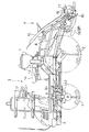
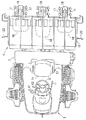
図1に、本発明に係る水田作業機の一例である、乗用型田植機の全体側面が、また、図2にその全体平面がそれぞれ示されている。この田植機は、前輪1および後輪2を備えた4輪駆動式の乗用走行機体3の後部に、水田作業装置として6条植え仕様の苗植付け装置4が、油圧シリンダ5によって駆動される平行四連リンク構造の昇降リンク機構6を介して昇降可能に連結されるとともに、機体後部に施肥装置7が備えられた基本構造を有している。
FIG. 1 shows an entire side surface of a riding type rice transplanter, which is an example of a paddy field working machine according to the present invention, and FIG. In this rice transplanter, a 6-row planting
前記走行機体3の前部にはガソリン仕様のエンジン8が搭載され、その出力が前後進の切り換えが可能な主変速装置である静油圧式の無段変速装置(HST)9にベルト伝達され、その変速出力がミッションケース10に入力されて更に副変速装置(図示せず)で高低2段にギヤ変速された後、前輪1と後輪2に伝達されるようになっている。また、ミッションケース10内で走行系から分岐された作業用動力が苗植付け装置4に軸伝達されるようになっている。そして、前記無段変速装置9を操作する変速レバー11が、搭乗運転部のステアリングハンドル12の左脇に前後揺動可能に配備されるとともに、ミッションケース10内の副変速装置を操作する副変速レバー13が、搭乗運転部の運転座席14の左脇に配備され、さらに、搭乗運転部の右前足元には、踏み込みによってミッションケース10内の主クラッチを切るとともに走行系に備えたブレーキを制動作動させる機体停止用のペダル15が配備されている。
A
前記苗植付け装置4には、苗を載置して一定ストロークで往復横移動する苗のせ台16と、この苗のせ台16の下端から一株分づつ苗を切り出して植付ける6組の回転式の植付け機構17と、圃場の植付け予定箇所を均平にする3個の整地フロート18、等が装備されており、後向き片持ち状に並列支持した3個の植付けケース19の後部左右に植付け機構17が2組づつ装着されている。また、苗植付け装置4には、往復植付け形態での一行程の植付け走行中に、Uターン後の次行程における走行基準線を未植え側の田面に引っ掻き形成する左右一対の線引きマーカー20が、横側方に突出する作用姿勢と起立された格納姿勢とに切換え揺動自在に備えられており、この線引きマーカー20は苗植付け装置4の上昇に連動して格納揺動されてロックされ、ロック解除された線引きマーカー20だけが苗植付け装置4の下降時に作用姿勢に付勢揺動するよう構成されている。
The
3個の前記整地フロート18は、それぞれ後支点を中心に上下揺動可能に支持されるとともに、中央の整地フロート18は、苗植付け装置4を田面に対して追従昇降制御するためのセンサフロートSFとして利用されている。つまり、このセンサフロートSFの上下位置がポテンショメータからなるセンサ21で検出され、その検出値と予め設定された基準値とが制御装置22で比較され、センサ21からの検出値が基準値に保持されるように前記油圧シリンダ5の電磁制御弁23を作動制御して苗植付け装置4を昇降させることで、苗植付け装置4を田面に対して追従させる自動昇降制御装置が構成されている。
The three
前記変速レバー11は走行速度を変更するのみならず、他の機構部位を作動させる複合操作レバーとしての機能を発揮するものであり、そのいくつかの例を以下に説明する。
The
〔第1例〕 [First example]
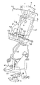
図3〜図5に、変速操作構造の第1例が示されている。この例では、変速レバー11はエンジン8のアクセル調節レバーおよび苗植付け装置上昇用レバーとしての機能をも併せ持っている。つまり、エンジン8に備えられた調速機構25は、調速レバー26の操作位置に対応してエンジン回転速度が設定範囲内に安定維持されるように、エンジン回転速度変動に基づいてスロットル開度を自動調節するよう構成されたものであり、周知のメカニカルガバナが使用されている。そして、減速機付きの電動モータ27で駆動される作動レバー28と前記調速レバー26とが操作ワイヤ29で連係され、調速機構25のアクセルセット作動が電動モータ27を介して電気的に実行されるようになっている。そして、前記電動モータ27は前記制御装置22によって作動制御されるようになっており、この制御装置22に、前記変速レバー11の操作位置を検出するポテンショメータ30、作動レバー28の作動位置を検出するフィードバック用のポテンショメータ31、が接続されており、これらの検知情報に基づいて電動モータ27が作動制御されて、前記調速機構25のアクセルセット操作が以下のように行われる。
3 to 5 show a first example of a speed change operation structure. In this example, the
ここで、図3に示すように、変速レバー11は、固定枠41に横向き水平支点a周りに回動自在に支持された支持板42に前後向き支点b周りに横揺動自在に支持されて、固定のレバーガイド43から上方に挿通延出されており、変速レバー11と一体回動する前記支持板42から下方に向けて延出された操作ロッド44が、支点c周りに回動自在なベルクランク45、および、ロッド46を介して無段変速装置9の変速操作軸47に設けた操作アーム48に機械的に連動連結されている。また、変速レバー11の支点部から下方に屈曲延出した案内ロッド部11aが固定枠41に取付けられたガイド板49のガイド溝50に挿通案内されることでレバー移動径路が規制されている。前記ガイド溝50は前後方向に向かう段違い状に形成されており、レバーガイド上方から見た操作径路は、図5に示すように、前進変速操作径路Fと後進変速操作径路Rとが、互いに平行、かつ、段違い状に偏位されて中立位置Nで連通接続された状態になっている。
Here, as shown in FIG. 3, the
前記支持板42の外周には多数(この例では9個)の位地決め用の凹部51が形成されるとともに、この凹部49のいずれか一つに板バネ製のデテントレバー52の先端ローラ53が弾性係入して、変速レバー11を複数の操作位置に保持するように構成されている。具体的には、前進変速操作径路Fでは、中立位置Nの他に5段の前進変速位置f1〜f5が設定されるとともに、後進変速操作径路Rでは、中立位置Nの他に3段の後進変速位置r1〜r3が設定されている。
A large number (9 in this example) of positioning recesses 51 are formed on the outer periphery of the
なお、詳細な構造は省略するが、前記ベルクランク45と前記機体停止用のペダル15とが機械的に接当連係されており、前進あるいは後進中にペダル15を踏み込んで、主クラッチを切るとともにブレーキを制動操作して機体停止を行うと、ベルクランク45が踏力の一部によって強制的に中立まで接当回動され、変速レバー11が中立位置Nに強制復帰移動されるようになっている。
Although the detailed structure is omitted, the bell crank 45 and the
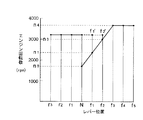
図6に、変速レバー11の変速位置とエンジン8の目標回転速度(アクセルセット速度)との関係が示されている。つまり、変速レバー11が中立位置Nにあると、目標回転速度がアイドリング回転速度n0(例えば1700rpm)に設定されるとともに、中立位置Nから前進3速[f3]までは直線的に増速され、前進3速[f3]から前進5速[f5]までは最高回転速度n4(例えば3600rpm)に設定され、前進1速[f1]では第1設定回転速度n1(例えば2500rpm)、前進2速[f2]では第2設定回転速度n2(例えば3000rpm)が現出される。また、後進変速操作径路Rでは目標回転速度は最高回転速度より少し低い第3設定回転速度n3(例えば3200rpm)に設定されている。
FIG. 6 shows the relationship between the speed change position of the
この場合、変速レバー11による変速セットとアクセルセットの関係特性が予め記憶設定されており、変速レバー11の操作位置に対応した調速レバー26の目標回転速度セット位置が割り出され、この割り出された目標回転速度セット位置に向けて調速レバー26を移動させるように電動モータ27がフィードバック制御され、変速レバー11の操作位置に対応したアクセルセットが自動的に行われるのである。
In this case, the relationship between the speed change set by the
また、後進変速操作径路Rの中立位置N(r)から引き続く前進方向への直線移動操作によって移行可能な副前進変速操作径路F’が、正規の前進変速操作径路Fにおける低速側部分(1速[f1]から2速[f2])の横側に連設されている。従って、変速レバー11を副前進変速操作径路F’と後進変速操作径路Rに亘って直線的に操作して速やかな前後進切換え変速〔シャトル変速〕を行うことができるようになっている。このシャトル変速による前進最高速度は副前進変速操作径路F’の前端によって2速[f2]に制限されるので、不用意に後進から前進高速に切換えてしまうおそれはない。
Further, the sub-forward shift operation path F ′ that can be shifted by the linear movement operation in the forward direction from the neutral position N (r) of the reverse shift operation path R is a low-speed side portion (first speed) in the regular forward shift operation path F. [F1] to the second speed [f2]) are provided continuously. Therefore, the
また、レバー操作径路脇には、変速レバー11が後進変速操作径路Rあるいは副前進変速操作径路F’に在ることを検知する手段が配備されている。このレバー位置検出手段は、後進変速操作径路Rあるいは副前進変速操作径路F’に在る変速レバー11に接当揺動操作される感知レバー56と、その揺動を検知するスイッチ57とで構成されており、このスイッチ57と前記ポテンショメータ30との検出情報から、変速レバー11が後進変速操作径路Rに在るか、副前進変速操作径路F’に在るかが判断され、後進変速操作径路Rに在ることが判断されると、上記のように最高速度より低い第3設定回転速度n3にアクセルセットがなされるとともに、副前進変速操作径路F’に在ることが判断された場合も、後進変速操作径路Rと同じ第3設定回転速度n3にアクセルセットされる。
A means for detecting that the
また、変速レバー11が正規の前進変速操作径路Fから副前進変速操作径路F’に操作されたことが判断されると、苗植付け装置4の強制上昇制御が実行されるとともに、変速レバー11が後進側の中立位置N(r)および後進変速操作径路Rに操作されたことが判断されることによっても苗植付け装置4の強制上昇制御が実行されるようになっている。つまり、変速レバー11が副前進変速操作径路F’に操作されての低速前進での自動上昇制御〔低速アップ制御〕と、後進される際の自動上昇制御〔バックアップ制御〕が実行されて、苗植付け装置4が優先的に上限まで駆動上昇されるようになっているのである。
When it is determined that the
ここで、低速アップ制御が行われる副前進変速操作径路F’で前進速度(f1‘〜f2’)が選択されると、前進変速操作径路Fで同じ前進速度(f1〜f2)が選択される場合よりもエンジン回転速度が高く(後進時のエンジン回転速度と同じ)アクセルセットされているので、エンジン8に直結された油圧ポンプからの吐出量が十分確保され、油圧シリンダ5の作動速度が速いものとなって、苗植付け装置4は速やかに上昇されることになる。
Here, when the forward speed (f1 ′ to f2 ′) is selected in the auxiliary forward speed change operation path F ′ in which the low speed up control is performed, the same forward speed (f1 to f2) is selected in the forward speed change operation path F. Since the engine speed is higher than the case (same as the engine speed during reverse travel) and the accelerator is set, a sufficient discharge amount from the hydraulic pump directly connected to the
また、前記制御装置22には、前輪1の中立からの切れ角度を検知する操向角センサ58が接続されており、前輪1が設定角度(例えば30度)以上に大きく操向されたことが検知されると、苗植付け装置4を自動的に上昇させる制御〔オートアップ制御〕が実行されるようになっている。また、このオートアップ制御は切換えスイッチ59によってオン・オフ操作可能となっており、変形圃場ではスイッチ59をオフ位置に切換えてオートアップ制御を停止しておくことで、機体を大きく操向する機会の多い曲線植付け走行時に、オートアップ制御によって不用意に苗植付け装置4が上昇されてしまうことを回避することができる。そして、切換えスイッチ59によってオートアップ制御を停止していても、変速レバー11の操作位置の判断に基づく前記低速アップ制御とバックアップ制御は常に優先的に実行されるようになっている。
Further, the
また、上記した低速アップ制御、バックアップ制御、および、オートアップ制御が働いて苗植付け装置4が駆動上昇されると、苗植付け装置4への動力伝達を断続する作業クラッチとしての植付けクラッチ60(ミッションケース10に内装)が電動モータ61によって切り操作されるようになっている。
In addition, when the above-described low-speed up control, backup control, and auto-up control are activated and the
なお、前記ステアリングハンドル12の右脇には、中立復帰付勢された十字揺動式の操作レバー62が配備されるとともに、この操作レバー62の上下操作が図示しないスイッチによって検出されるようになっている。そして、この操作レバー62を中立から1回上方に操作することで、苗植付け装置4が優先的に上限まで駆動上昇されるとともに、植付けクラッチ60が電動モータ61によって切り操作される。また、苗植付け装置4が上昇されている状態で操作レバー62を中立から1回下方に操作することで、苗植付け装置4が優先的に下降される。また、この下降操作の後に操作レバー62を中立から2回目に再度下げ操作することで、植付けクラッチ60が電動モータ61によって入り操作され、苗植付け装置4の駆動が開始されるようになっている。
A cross swing
また、操作レバー62を前方に揺動操作すると、左側の線引きマーカー20の格納ロックが解除されるとともに、操作レバー62を後方に揺動操作すると、右側の線引きマーカー20の格納ロックが解除されるように、操作レバー62と図示しないマーカー格納ロック機構とが機械的にワイヤ連係されている。
Further, when the
〔第2例〕 [Second example]
上記第1例と同じ構造において、変速レバー11が前進変速操作径路Fから副前進変速操作径路F’に操作されたことが判断されると、苗植付け装置4の強制上昇制御が実行されるとともに植付けクラッチ60が切られ、変速レバー11が再び前進変速操作径路Fから副前進変速操作径路F’に操作されたことが判断されると、苗植付け装置4の強制下降制御が実行されるように、つまり、変速レバー11が副前進変速操作径路F’に操作されるたびに苗植付け装置4の上昇制御と下降制御を交互に行うように構成することもできる。
In the same structure as the first example, when it is determined that the
〔第3例〕 [Third example]
図7に第3例における変速操作径路が示されている。この例は、前記第1例における副前進変速操作径路F’を前進変速操作径路Fの全域の横側に形成したものであり、前後進切換えを直線操作で速やかに行うことができるとともに、変速レバー11を前進変速操作径路Fの任意の変速位置から副前進変速操作径路F’に横移動して苗植付け装置4を上昇作動させる形態で実施することもできる。
また、この第3例に前記第2例の技術を導入して、変速レバー11が副前進変速操作径路F’に操作されるたびに苗植付け装置4の上昇制御と下降制御を交互に行うように構成することもできる。
FIG. 7 shows the speed change operation path in the third example. In this example, the auxiliary forward speed change operation path F ′ in the first example is formed on the lateral side of the entire area of the forward speed change operation path F, and the forward / reverse switching can be quickly performed by a linear operation. The
In addition, the technique of the second example is introduced into the third example so that the raising control and the lowering control of the
〔第4例〕 [Fourth example]
図8に第4例における変速操作径路が示されている。この例は、前記第1例の構造において、後進変速操作径路Rと副前進変速操作径路F’との間に隔壁65を形成したものであり、直線操作による前後進切換え(シャトル変速)はできないが、変速レバー11による低速アップ制御とバックアップ制御を行うことができる。
この場合も、第2例のように、変速レバー11が副前進変速操作径路F’に操作されるたびに苗植付け装置4の上昇制御と下降制御を交互に行うように構成することもできる。
FIG. 8 shows the speed change operation path in the fourth example. In this example, in the structure of the first example, a
Also in this case, as in the second example, the raising control and the lowering control of the
〔第5例〕 [Fifth example]
図9に第5例における変速操作径路が示されている。この例は、前記第1例を基本構造として、上記副前進変速操作径路F’よりも高速で、最高速度[f5]より低速である中速位置[f4]において前進変速操作径路Fから左右にマーカー選択操作径路ML,MRが延出されている。また、この例では、副前進変速操作径路F’の全域と、後進変速操作径路Rの中立位置N(r)から後進2速までの低速域では支持板42に位置決め用のノッチ51がなく、無段階に変速保持することができるようになっている。また、変速レバー11が副前進変速操作径路F’に操作されるたびに苗植付け装置4の上昇制御と下降制御を交互に行うように構成されている。さらに、マーカー選択操作径路ML,MRのいずれかに操作することで、植付けクラッチ60が電動モータ61によって入れられるようになっている。この例では、変速レバー11で苗植付け装置4の昇降、植付けクラッチ60の入り切り、および、線引きマーカー20の選択まで行うことができるので、第1例における操作レバー62は不要となっている。
FIG. 9 shows a speed change operation path in the fifth example. In this example, based on the first example, the basic structure is the left and right from the forward speed change operation path F at the middle speed position [f4], which is faster than the auxiliary forward speed change operation path F ′ and lower than the maximum speed [f5]. Marker selection operation paths ML and MR are extended. Further, in this example, the
この構成によると、一行程の植付け走行を終えた畦際において、変速レバー11を副前進変速操作径路F’に操作することで、走行速度を減速するとともに、低速アップ制御で苗植付け装置4を上昇させ、かつ、植付けクラッチ60を切ることができ、この状態で機体の方向転換を行う。そして、方向転換が終了しかかると、変速レバー11を前進変速操作径路Fから再度副前進変速操作径路F’に操作することで苗植付け装置4を、植付けクラッチ60が切られたままの状態で田面まで下降させる。条合わせを行った後、変速レバー11を前進変速操作径路Fの中速位置[f4]に増速操作して左右のマーカー選択操作径路ML,MRの一方に操作することで、左右いずれかの線引きマーカー20を作用姿勢に突出させることができる。そして、この例の場合、変速レバー11をマーカー選択操作径路ML,MRのいずれかに操作することで、植付けクラッチ60が電動モータ61によって入れられ、中速度での植付け走行が開始されることになる。その後、必要に応じて、変速レバー11を最高速度[f5]を選択して、能率的な植付け走行を行うことができる。
According to this configuration, when the planting traveling of one stroke is finished, the shifting
〔第6例〕 [Sixth example]
図10に第6例における変速操作径路が示されている。この例は、上記第5例を変形したものであり、マーカー選択操作径路ML,MRは、前進変速操作径路Fの最高速度位置から左右に延出され、かつ、図示しないが、変速レバー11の握り部に植付けクラッチ入り切り用のスイッチが指操作可能に備えられている。 FIG. 10 shows the speed change operation path in the sixth example. This example is a modification of the fifth example described above, and the marker selection operation paths ML and MR extend from the maximum speed position of the forward shift operation path F to the left and right, and although not shown, A switch for turning on and off the planting clutch is provided on the grip so that the finger can be operated.
この構成によると、一行程の植付け走行を終えた畦際において、変速レバー11を副前進変速操作径路F’に操作することで、走行速度を減速するとともに、低速アップ制御で苗植付け装置4を上昇させ、かつ、植付けクラッチ60を切ることができ、この状態で機体の方向転換を行う。そして、方向転換が終了しかかると、変速レバー11を前進変速操作径路Fから再度副前進変速操作径路F’に操作することで苗植付け装置4を、植付けクラッチ60が切られたままの状態で田面まで下降させる。条合わせを行った後、変速レバー11を前進変速操作径路Fの最高速度位置[f5]に増速操作して左右のマーカー選択操作径路ML,MRの一方に操作することで、左右いずれかの線引きマーカー20を作用姿勢に突出させることができる。そして、この例の場合、変速レバー11をマーカー選択操作径路ML,MRのいずれかに操作することで、植付けクラッチ60が電動モータ61によって入れられ、高速での植付け走行が開始されることになる。
According to this configuration, when the planting traveling of one stroke is finished, the shifting
ここで、植付けクラッチ60は変速レバー11の握り部に設けたスイッチによっても入り操作できるので、条合わせを行った後、変速レバー11を前進変速操作径路Fの任意の位置に操作するとともに、そのスイッチを操作して植付けクラッチ60を入れて植付け走行を開始し、その後に左右のマーカー選択操作径路ML,MRの一方に操作して所要の線引きマーカー20を作用姿勢に切換えることもできる。
Here, since the planting
また、田植え作業の形態としては、畦際に一行程分のスペースを空けて往復植えを開始し、往復植えが終了した後に畦際に沿って周り植えを行う形態あり、この場合、往復植えを開始する前に、一方の線引きマーカー20を作用姿勢に切換えて植付けを行わないで線引きだけを行う走行時には、マーカー選択操作径路ML,MRの一方を操作して線引きマーカー20を作用姿勢に切換えた後に、変速レバー11のスイッチを指操作して植付けクラッチ60を切ることができる。
In addition, as a form of rice planting work, there is a form in which a space for one stroke is made at the heel and the round trip planting is started, and after the round trip planting is completed, the surrounding planting is carried out along the heel. Before starting, when one of the
〔第7例〕 [Seventh example]
図11に第7例における変速操作径路が示されている。この例では、前進変速操作径路Fにおいて変速レバー11は、左右に操作可能、かつ、横方向操作の中立に復帰付勢されており、低速域において変速レバー11が左方へ横操作されることで苗植付け装置4が上昇されるとともに植付けクラッチ60が切り操作され、変速レバー11が右方へ横操作されることで苗植付け装置4が下降され、更に、苗植付け装置4が下降操作された後の2回目の右方への横操作で植付けクラッチ60が入り操作されるようになっている。
FIG. 11 shows the speed change operation path in the seventh example. In this example, the
また、前進変速操作径路Fの中速位置からは左右にマーカー選択操作径路ML,MRが延出されており、このマーカー選択操作径路ML,MRへの選択操作によって操作された側の線引きマーカー20の格納ロックが解除されるとともに、植付けクラッチ60が入り操作されるようになっている。
Further, marker selection operation paths ML and MR are extended from the middle speed position of the forward speed change operation path F to the left and right, and the
〔第8例〕 [Eighth example]
図12に第8例における変速操作径路が示されている。この例は、上記第7例を変形したものであり、前記マーカー選択操作径路ML,MRが前進変速操作径路Fの最高速度位置から延出され、前進変速操作径路Fの全域において、左方への横操作で苗植付け装置4が上昇されるとともに植付けクラッチ60が切り操作され、変速レバー11が右方へ横操作されることで苗植付け装置4が下降され、更に、苗植付け装置4が下降操作された後の2回目の右方への横操作で植付けクラッチ60が入り操作されるようになっている。
FIG. 12 shows the speed change operation path in the eighth example. This example is a modification of the seventh example, and the marker selection operation paths ML and MR are extended from the maximum speed position of the forward shift operation path F, and to the left in the entire area of the forward shift operation path F. When the
3 走行機体
4 水田作業装置
8 エンジン
11 変速レバー
25 調速機構
F 前進変速操作径路
R 後進変速操作径路
N 中立位置
3 traveling
Claims (2)
走行速度を無段に変速する変速レバーを、前進変速操作径路から後進変速操作径路に亘って中立位置を介して一連に移動操作可能に構成し、
走行機体の操向操作に連動して前記水田作業装置を自動的に上昇させるオートアップ制御手段と、
前記変速レバーが前記後進変速操作径路に操作されることに連動して前記水田作業装置を自動的に上昇させるバックアップ制御手段とを備え、
前記変速レバーとエンジンの調速機構を連係して、前記変速レバーを前記前進変速操作径路において中立位置から高速位置側へ操作するに連れて前記調速機構を直線的に高回転側に作動させ、前記変速レバーを中立位置側へ操作するに連れて前記調速機構を直線的に低回転側に作動させるように設定し、
前記前進変速操作径路に複数段の前進変速位置を設定し、前記後進変速操作径路に複数段の後進変速位置を設定して、
後進1速に対応したエンジンの回転速度を前進1速に対応したエンジンの回転速度よりも大きく設定し、且つ、前記後進変速操作径路において前記変速レバーの最高速位置に対応したエンジンの回転速度を前記前進変速操作径路における前記変速レバーの最高速位置に対応したエンジンの回転速度よりも小さく設定し、
前記バックアップ制御手段が前記オートアップ制御手段に優先して実行されるように構成してある水田作業機。 The paddy field work device is connected to the traveling machine body so that it can be driven up and down freely.
A speed change lever that continuously changes the traveling speed is configured to be movable in a series of positions through a neutral position from the forward speed change operation path to the reverse speed change operation path.
Auto-up control means for automatically raising the paddy field work device in conjunction with the steering operation of the traveling machine;
And a backup control means for automatically increasing the paddy working device in conjunction with said shift lever is operated to the reverse shift operation path,
In conjunction with speed control mechanism of the shift lever and the engine, linearly actuated in the high speed side of the speed control mechanism As the operated from the neutral position to the high speed position side said shift lever in the forward shift operation path , Setting the speed control mechanism linearly to the low rotation side as the shift lever is operated to the neutral position side,
A plurality of forward shift positions are set in the forward shift operation path, and a plurality of reverse shift positions are set in the reverse shift operation path;
The rotational speed of the engine corresponding to the first reverse speed is set to be larger than the rotational speed of the engine corresponding to the first forward speed, and the rotational speed of the engine corresponding to the highest speed position of the shift lever in the reverse speed change operation path is set. Set smaller than the rotational speed of the engine corresponding to the highest speed position of the shift lever in the forward shift operation path;
Paddy working machine that is configured to be executed in priority to the backup control unit the auto-up control means.
走行速度を無段に変速する変速レバーを、前進変速操作径路から後進変速操作径路に亘って中立位置を介して一連に移動操作可能に構成し、
走行機体の操向操作に連動して前記水田作業装置を自動的に上昇させるオートアップ制御手段と、
前記変速レバーが前記後進変速操作径路に操作されることに連動して前記水田作業装置を自動的に上昇させるバックアップ制御手段とを備え、
前記変速レバーとエンジンの調速機構を連係して、前記変速レバーを前記前進変速操作径路において中立位置から高速位置側へ操作するに連れて前記調速機構を直線的に高回転側に作動させ、前記変速レバーを中立位置側へ操作するに連れて前記調速機構を直線的に低回転側に作動させるように設定し、
前記前進変速操作径路に複数段の前進変速位置を設定し、前記後進変速操作径路に複数段の後進変速位置を設定して、
後進1速に対応したエンジンの回転速度と、前進1速及び前進2速に対応したエンジンの回転速度とを同じに設定し、且つ、前記後進変速操作径路において前記変速レバーの最高速位置に対応したエンジンの回転速度を前記前進変速操作径路における前記変速レバーの最高速位置に対応したエンジンの回転速度よりも小さく設定し、
前記バックアップ制御手段が前記オートアップ制御手段に優先して実行されるように構成してある水田作業機。 The paddy field work device is connected to the traveling machine body so that it can be driven up and down freely.
A speed change lever that continuously changes the traveling speed is configured to be movable in a series of positions through a neutral position from the forward speed change operation path to the reverse speed change operation path.
Auto-up control means for automatically raising the paddy field work device in conjunction with the steering operation of the traveling machine;
Backup control means for automatically raising the paddy field work device in conjunction with the shift lever being operated on the reverse shift operation path;
The speed change lever and the engine speed control mechanism are linked so that the speed control mechanism is linearly operated to the high speed side as the speed change lever is operated from the neutral position to the high speed position side in the forward speed change operation path. , Setting the speed control mechanism linearly to the low rotation side as the shift lever is operated to the neutral position side,
A plurality of forward shift positions are set in the forward shift operation path, and a plurality of reverse shift positions are set in the reverse shift operation path;
The engine speed corresponding to the first reverse speed and the engine speed corresponding to the first forward speed and the second forward speed are set to be the same, and the maximum speed position of the speed change lever in the reverse speed change operation path is set. The engine rotational speed is set smaller than the engine rotational speed corresponding to the highest speed position of the shift lever in the forward shift operation path,
A paddy field machine configured such that the backup control means is executed in preference to the auto-up control means .
Priority Applications (1)
| Application Number | Priority Date | Filing Date | Title |
|---|---|---|---|
| JP2011266224A JP5346367B2 (en) | 2011-12-05 | 2011-12-05 | Paddy field machine |
Applications Claiming Priority (1)
| Application Number | Priority Date | Filing Date | Title |
|---|---|---|---|
| JP2011266224A JP5346367B2 (en) | 2011-12-05 | 2011-12-05 | Paddy field machine |
Related Parent Applications (1)
| Application Number | Title | Priority Date | Filing Date |
|---|---|---|---|
| JP2001302925A Division JP5027366B2 (en) | 2001-08-10 | 2001-09-28 | Paddy field machine |
Publications (2)
| Publication Number | Publication Date |
|---|---|
| JP2012085646A JP2012085646A (en) | 2012-05-10 |
| JP5346367B2 true JP5346367B2 (en) | 2013-11-20 |
Family
ID=46257979
Family Applications (1)
| Application Number | Title | Priority Date | Filing Date |
|---|---|---|---|
| JP2011266224A Expired - Fee Related JP5346367B2 (en) | 2011-12-05 | 2011-12-05 | Paddy field machine |
Country Status (1)
| Country | Link |
|---|---|
| JP (1) | JP5346367B2 (en) |
Families Citing this family (1)
| Publication number | Priority date | Publication date | Assignee | Title |
|---|---|---|---|---|
| CN112913404A (en) * | 2021-02-22 | 2021-06-08 | 福州外语外贸学院 | Protection device is transplanted to plant for hydraulic engineering |
Family Cites Families (8)
| Publication number | Priority date | Publication date | Assignee | Title |
|---|---|---|---|---|
| JPH0685643B2 (en) * | 1987-01-16 | 1994-11-02 | 株式会社クボタ | Walk-type paddy work machine |
| JP3245458B2 (en) * | 1992-09-30 | 2002-01-15 | 株式会社クボタ | Work vehicle ground work equipment lifting structure |
| JPH0965720A (en) * | 1995-09-04 | 1997-03-11 | Kubota Corp | Rice transplanting machine |
| JP3696716B2 (en) * | 1997-05-29 | 2005-09-21 | ヤンマー農機株式会社 | Combined engine speed control mechanism |
| JPH11257474A (en) * | 1998-03-12 | 1999-09-21 | Yanmar Diesel Engine Co Ltd | Working vehicle |
| JP2000161089A (en) * | 1998-11-27 | 2000-06-13 | Iseki & Co Ltd | Accelerator control device for reaping vehicle |
| JP3750381B2 (en) * | 1998-11-30 | 2006-03-01 | 井関農機株式会社 | Accelerator control device for mowing vehicle |
| JP3883337B2 (en) * | 1999-09-24 | 2007-02-21 | 株式会社クボタ | Paddy field machine |
-
2011
- 2011-12-05 JP JP2011266224A patent/JP5346367B2/en not_active Expired - Fee Related
Also Published As
| Publication number | Publication date |
|---|---|
| JP2012085646A (en) | 2012-05-10 |
Similar Documents
| Publication | Publication Date | Title |
|---|---|---|
| KR101224751B1 (en) | Speed control structure for work vehicle, information display structure therefor, and speed shift manipulating structure therefor | |
| KR101542440B1 (en) | Traveling agricultural machine | |
| JP2010216563A (en) | Maximum speed control mechanism for work vehicle | |
| JP5346317B2 (en) | Paddy field machine | |
| JP5215491B2 (en) | Paddy field machine | |
| JP5330353B2 (en) | Work vehicle | |
| JP5560542B2 (en) | Seedling planting machine | |
| JP2010166929A5 (en) | ||
| JP5346367B2 (en) | Paddy field machine | |
| JP3998488B2 (en) | Shifting structure of work equipment | |
| JP2010029134A5 (en) | ||
| JP2005119466A (en) | Running transmission for working vehicle | |
| JP2010213620A (en) | Sensitivity control mechanism of gearshift tool in rice transplanter | |
| JP5027366B2 (en) | Paddy field machine | |
| JP6323918B2 (en) | Work vehicle | |
| JP2005140242A (en) | Shift control device for working vehicle | |
| JP2018127214A (en) | Work vehicle | |
| JP5567284B2 (en) | Rice transplanter | |
| JP2016185125A (en) | Work vehicle | |
| JP2019011766A (en) | Working vehicle | |
| JP5997242B2 (en) | Work vehicle | |
| JP5762482B2 (en) | Work vehicle | |
| KR100448944B1 (en) | Paddy field working vehicle | |
| JP2011193816A (en) | Rice transplanter | |
| JP2008008492A (en) | Shift control device for working vehicle |
Legal Events
| Date | Code | Title | Description |
|---|---|---|---|
| A131 | Notification of reasons for refusal |
Free format text: JAPANESE INTERMEDIATE CODE: A131 Effective date: 20120524 |
|
| A521 | Request for written amendment filed |
Free format text: JAPANESE INTERMEDIATE CODE: A523 Effective date: 20120717 |
|
| A02 | Decision of refusal |
Free format text: JAPANESE INTERMEDIATE CODE: A02 Effective date: 20130131 |
|
| A521 | Request for written amendment filed |
Free format text: JAPANESE INTERMEDIATE CODE: A523 Effective date: 20130423 |
|
| A521 | Request for written amendment filed |
Free format text: JAPANESE INTERMEDIATE CODE: A821 Effective date: 20130423 |
|
| A911 | Transfer to examiner for re-examination before appeal (zenchi) |
Free format text: JAPANESE INTERMEDIATE CODE: A911 Effective date: 20130517 |
|
| TRDD | Decision of grant or rejection written | ||
| A01 | Written decision to grant a patent or to grant a registration (utility model) |
Free format text: JAPANESE INTERMEDIATE CODE: A01 Effective date: 20130801 |
|
| A61 | First payment of annual fees (during grant procedure) |
Free format text: JAPANESE INTERMEDIATE CODE: A61 Effective date: 20130816 |
|
| R150 | Certificate of patent or registration of utility model |
Ref document number: 5346367 Country of ref document: JP Free format text: JAPANESE INTERMEDIATE CODE: R150 Free format text: JAPANESE INTERMEDIATE CODE: R150 |
|
| LAPS | Cancellation because of no payment of annual fees |