JP5345401B2 - Chain noise attenuator - Google Patents
Chain noise attenuator Download PDFInfo
- Publication number
- JP5345401B2 JP5345401B2 JP2008552532A JP2008552532A JP5345401B2 JP 5345401 B2 JP5345401 B2 JP 5345401B2 JP 2008552532 A JP2008552532 A JP 2008552532A JP 2008552532 A JP2008552532 A JP 2008552532A JP 5345401 B2 JP5345401 B2 JP 5345401B2
- Authority
- JP
- Japan
- Prior art keywords
- sprocket
- ring
- groove
- annular
- chain
- Prior art date
- Legal status (The legal status is an assumption and is not a legal conclusion. Google has not performed a legal analysis and makes no representation as to the accuracy of the status listed.)
- Expired - Fee Related
Links
Images


Classifications
-
- F—MECHANICAL ENGINEERING; LIGHTING; HEATING; WEAPONS; BLASTING
- F16—ENGINEERING ELEMENTS AND UNITS; GENERAL MEASURES FOR PRODUCING AND MAINTAINING EFFECTIVE FUNCTIONING OF MACHINES OR INSTALLATIONS; THERMAL INSULATION IN GENERAL
- F16H—GEARING
- F16H55/00—Elements with teeth or friction surfaces for conveying motion; Worms, pulleys or sheaves for gearing mechanisms
- F16H55/02—Toothed members; Worms
- F16H55/30—Chain-wheels
- F16H2055/306—Chain-wheels with means providing resilience or vibration damping in chain sprocket wheels
Description
本発明は、チェーン駆動動力伝達システムに使用される歯形スプロケットの分野に関する。より詳しくは、本発明は、チェーンのリンクとスプロケットの歯との係合に関連するノイズを減衰する装置に関する。 The present invention relates to the field of tooth sprockets used in chain drive power transmission systems. More particularly, the present invention relates to an apparatus for attenuating noise associated with the engagement of chain links and sprocket teeth.
チェーンおよびスプロケットは、動力を伝達するための手段、タイミング回転構成要素等として長年使用されてきた。このようなチェーンおよびスプロケットの構造に関連する1つの問題は、チェーンとスプロケットとが係合するときにチェーンローラまたはチェーンリンクがスプロケットに衝突することである。この衝突により、過剰なノイズおよび過剰な摩耗が発生する。この衝突およびそれに関連するノイズは、12で概略的に示されているチェーンのローラ10がスプロケット16の歯14に衝突することによって生じるものとして図1に示されている。チェーンの移動に沿って分布曲線20で示されているように発生する最もうるさいノイズは、係合開始点18で発生すると言われている。
Chains and sprockets have been used for many years as a means for transmitting power, timing rotating components, and the like. One problem associated with such chain and sprocket structures is that the chain roller or chain link impacts the sprocket when the chain and sprocket are engaged. This collision causes excessive noise and excessive wear. This collision and the associated noise are shown in FIG. 1 as being caused by the
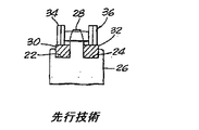
従来のローラチェーンおよびスプロケット連結部に関連するノイズおよび摩耗に対して、上記問題を低減するための装置が開発されてきた。これらの装置により、点18のこの範囲でチェーンの衝撃を緩衝しようと試みられてきた。このような第1の装置は、図2と図3に示されており、スプロケット26のスプロケット歯28の両側に円形の周溝22と24を含む。溝22と24内には、弾性的に圧縮可能なバッファリング30と32が配置される。これらのバッファリング30と32は、材質が非常に弾性であるので、溝22と24にぴったりと嵌合する。図2と図3のバッファリングは、チェーン36のリンクプレート34に抗する際に、リング30と32の圧縮に対する弾性復元力による緩衝効果を提供する。この機構によって、うまくノイズが低減される。しかし、スプロケット26およびスプロケット歯28に対してバッファリング30と32の位置が固定されるので、装置が比較的非実用的になるほど、リング30と32の固定点で、急速な摩耗および疲労が引き起こされる。
Devices have been developed to reduce the above problems against noise and wear associated with conventional roller chain and sprocket connections. With these devices, attempts have been made to cushion the chain impact in this range of points 18. A first such device is shown in FIGS. 2 and 3 and includes circular
これまで知られている第2のタイプのバッファリングが図4と図5に示されている。また、スプロケット26は、金属バッファリング38と40を受け入れるために、スプロケット歯28の両側に円形の周溝22と24を含む。これらのバッファリングは、溝22と24のいずれかの外径よりも大きい内径を有する。さらに、バッファリング38と40は、スプロケットに係合するローラチェーンのリンクプレートの刻まれた円形部の下方における溝22と24の底部の深さ以下の半径方向厚さを有する。刻まれた円形部は図4に番号42で示されている。
A second type of buffering known so far is illustrated in FIGS. Sprocket 26 also includes circular
図4と図5に示されているようなこのタイプのバッファリングは、図4に示されているようにリングを円形から変形すべく機能するか、または円形のままであることができる。リング材自体は、図2と図3の装置のようにチェーン36のリンクプレートと溝22および24の底部との間で圧縮されない。金属バッファリングの利点は、それらの金属バッファリングが、スプロケット26の歯28に対する位置を常に変化させ、したがって、固定された摩耗箇所を有さないことである。しかし、リング38および40と溝22および24との間に依然として金属間接触があるので、最大のノイズ減少を実現できない。
This type of buffering as shown in FIGS. 4 and 5 can function to deform the ring from a circle as shown in FIG. 4 or can remain circular. The ring material itself is not compressed between the link plate of the
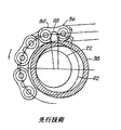
図6〜図8は、当業者によってよく知られているような従来のクッションリングスプロケットSを示している。スプロケットSは、そこから半径方向外側に突出する周方向に離間した複数の歯Tを備える環状部材または環状部Mを備える。歯Tは歯空間TSによって分離される。歯Tは、関連するチェーン(図示せず)に係合する。 6-8 illustrate a conventional cushion ring sprocket S as is well known by those skilled in the art. The sprocket S includes an annular member or an annular portion M that includes a plurality of circumferentially spaced teeth T projecting radially outward therefrom. Teeth T are separated by a tooth space TS. Teeth T engage an associated chain (not shown).
スプロケットSは、環状の歯形部Mに連結されるかまたはそれと一体構造のものとして画定されたハブHをさらに備える。ハブHの第1および第2の部分HI、H2は、環状部Mの第1および第2の対向側軸方向面F1、F2から軸方向外側に突出する。第1および第2のハブ部H1、H2は、それぞれの円筒外径ODI、OD2を含むかまたはそれらを画定する。上記のように、ハブHおよび環状部Mを、別個の構造から組み立てることができるかまたは一体の構造のものとして画定できる。環状の歯形部MおよびハブHは、共に、回転軸線Xを中心に回転するスプロケット本体Bを画定する。凹部または貫通穴Cは、回転軸線Xを中心とするハブに画定される。凹部または穴Cは、スプロケット本体Bと共に回転するかまたはそれを回転可能に支持するシャフトまたは他の部材を受け入れる。スプロケット本体Bは、典型的に、鋳造、機械加工、または粉末金属成形技術によって、適切な金属から構成される。しかし、他の適切な手段および/または材料を使用してもよい。 The sprocket S further comprises a hub H connected to the annular tooth profile M or defined as being integral therewith. The first and second portions HI, H2 of the hub H protrude outward in the axial direction from the first and second opposing axial surfaces F1, F2 of the annular portion M. The first and second hub portions H1, H2 include or define respective cylindrical outer diameters ODI, OD2. As described above, the hub H and the annulus M can be assembled from separate structures or can be defined as an integral structure. The annular tooth profile M and the hub H together define a sprocket body B that rotates about the rotation axis X. The recess or through hole C is defined in the hub about the rotation axis X. The recess or hole C receives a shaft or other member that rotates with or rotatably supports the sprocket body B. The sprocket body B is typically composed of a suitable metal by casting, machining, or powder metal forming techniques. However, other suitable means and / or materials may be used.
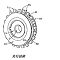
第1および第2の環状のクッションリングR1、R2が設けられて、ハブ部H1、H2のそれぞれの円筒外径OD1、OD2に緩く受け入れられ、すなわち、クッションリングR1、R2は、外径OD1、OD2でリングR1、R2を偏心して浮動できるようにリングが受け入れられる外径OD1、OD2よりも大きい内径ID1、ID2を画定する。 First and second annular cushion rings R1, R2 are provided and are loosely received in the respective cylindrical outer diameters OD1, OD2 of the hub portions H1, H2, ie, the cushion rings R1, R2 have an outer diameter OD1, Inner diameters ID1 and ID2 larger than outer diameters OD1 and OD2 that can be received by the ring are defined so that the rings R1 and R2 can be eccentrically floated at OD2.
クッションリングR1、R2は、ハブ部H1、H2のそれぞれに固定されるか、溶接されるか、または他の方法で連結される半径方向に拡大されたフランジG1、G2によって、ハブ部H1、H2に移動可能に捕捉されるかまたは繋ぎ留められる。フランジG1、G2は、面F1、F2とフランジG1、G2との間でクッションリングをそれぞれ緩く繋ぎ留めるために、クッションリング内径ID1、ID2よりも大きいそれぞれの円形外径OG1、OG2を画定する。 The cushion rings R1, R2 are fixed to the hub parts H1, H2 respectively, welded or otherwise connected by radially expanded flanges G1, G2 to the hub parts H1, H2. Movably captured or tethered to The flanges G1 and G2 define respective circular outer diameters OG1 and OG2 larger than the cushion ring inner diameters ID1 and ID2 in order to loosely fasten the cushion rings between the surfaces F1 and F2 and the flanges G1 and G2, respectively.
クッションリングR1、R2は、典型的に、金属から製造され、使用中に、スプロケット歯Tに係合する関連するチェーンのチェーンリンク(図示せず)に接触する。クッションリングR1、R2は、チェーンリンクの力を受けてハブ外径OD1、OD2で偏心して浮動し、関連するチェーンとスプロケットSとによる衝突を緩衝または緩和するように作用し、これにより、ノイズレベルが減少される。 The cushion rings R1, R2 are typically made from metal and in use contact the chain links (not shown) of the associated chain that engage the sprocket teeth T. The cushion rings R1 and R2 are eccentrically floated at the hub outer diameters OD1 and OD2 by receiving the force of the chain link, and act to buffer or mitigate the collision between the associated chain and the sprocket S, thereby reducing the noise level. Is reduced.
本発明は、チェーン係合ノイズを最小にしつつ、チェーン係合緩衝作用を最大にするチェーンおよびスプロケット連結部用のバッファ装置である。低い摩耗特性を有する環状のクッションリングは、スプロケットに係合したときに、チェーンリンクプレートによって形成された、刻まれた円形部よりも大きい外径を有する、スプロケット歯に隣接する溝に摺動可能に嵌合する。加圧粘性流体は、スプロケットハブを介してスプロケット溝とクッションリング内径との間のキャビティに導かれる。クッションリングの流体流量および軸方向移動は、スプロケットと、クッションリングと、スプロケットに圧入されることが好ましい半径方向フランジとの間の狭い間隙によって制限される。クッションリングおよび半径方向フランジは、スプロケット歯の一方の側または他方の側に限定されず、スプロケットハブの各側に適用することが可能である。 The present invention is a buffer device for a chain and sprocket coupling that maximizes chain engagement buffering action while minimizing chain engagement noise. Annular cushion ring with low wear characteristics, when engaged with the sprocket, can slide into the groove adjacent to the sprocket teeth, which has an outer diameter larger than the engraved circle formed by the chain link plate To fit. The pressurized viscous fluid is guided to the cavity between the sprocket groove and the cushion ring inner diameter through the sprocket hub. The fluid flow rate and axial movement of the cushion ring is limited by the narrow gap between the sprocket, the cushion ring, and the radial flange that is preferably press fit into the sprocket. The cushion ring and the radial flange are not limited to one side or the other side of the sprocket teeth, and can be applied to each side of the sprocket hub.
加圧流体が存在することによって、チェーンとスプロケットとの金属間接触が緩和されることにより、スプロケットハブへのクッションリングの衝突エネルギーの伝達、特にノイズが減衰され、このようにして、チェーン係合ノイズが低減される。 Due to the presence of pressurized fluid, the metal-to-metal contact between the chain and the sprocket is alleviated, so that the transmission of the impact energy of the cushion ring to the sprocket hub, especially noise, is attenuated, and thus the chain engagement Noise is reduced.
係合チェーンストランドが、最初にクッションリングに接触し、次にスプロケット歯に接触したときに、流体質量の運動効果により、衝撃吸収および振動低減が著しく改善される。このことにより、クッションリングの位置を変化させるようにチェーンの傾向が阻止され、このようにして、チェーン運動が減衰される。 When the engaging chain strand first contacts the cushion ring and then the sprocket teeth, the fluid mass motion effects significantly improve shock absorption and vibration reduction. This prevents the chain from tending to change the position of the cushion ring and thus attenuates the chain motion.
本発明のバッファ装置は、反転荷重の周期中に、すなわち、動作が急速なストランドと、動作が緩慢なストランドとの間でチェーンの引っ張りが交互に行われたときに、減衰を改善する。流体質量の運動が、交互のチェーンの引っ張りに関連するチェーン運動および衝突エネルギーを減衰し、ノイズ防止が有効に達成される。 The buffer device of the present invention improves damping during periods of reversal load, i.e., when chain pulls are alternated between fast acting and slow moving strands. The motion of the fluid mass attenuates the chain motion and collision energy associated with alternating chain pull, and noise prevention is effectively achieved.
本発明は、歯形チェーンまたはサイレントチェーン等の、ピンとリンクとを有するローラチェーンおよび他の形態の動力伝達チェーンに適用できる。 The present invention can be applied to a roller chain having a pin and a link, such as a tooth chain or a silent chain, and other types of power transmission chains.
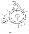
図9を参照すると、本発明の正面図が示されている。本発明は、支持ハウジング55によって内燃機関に確実に取り付けられる減衰スプロケット組立体10からなる。減衰スプロケット組立体10は、ハブ30と、環状部40と、周方向に連続する列の離間した半径方向突出歯25とを含むスプロケット20を含む。歯は、丸みを有する歯間隙26によって互いに分離される。各歯間隙26の丸みは、図12に最良に示されており、スプロケットに作動的に係合するチェーン(図示せず)の多数のローラの各々の丸みに適合するように設計される。スプロケット20は、力をチェーンに供給して、矢印F1で示したように他のスプロケットを駆動するか、または矢印F2で示したように、他のスプロケットからチェーンを介して駆動力を受けて、スプロケット20を駆動する。この力は、スプロケット20の歯間隙26内へのチェーンローラの係合によって伝達される。ローラとスプロケット20の歯間隙26との間の係合による衝突は、望ましくないNVH(ノイズ、振動、耳障り感)特性を生じさせる。
Referring to FIG. 9, a front view of the present invention is shown. The present invention comprises a damped
種々のタイプのドライブシャフトまたはドリブンシャフトに取り付けられるスプロケットに、本発明を利用し得る。限定的でない例は、ドライブシャフト、カムシャフトタイミング駆動装置、オイルポンプ駆動装置、バランスシャフト駆動装置および燃料ポンプ駆動装置を含む。 The present invention may be utilized with sprockets that are attached to various types of drive shafts or driven shafts. Non-limiting examples include drive shafts, camshaft timing drives, oil pump drives, balance shaft drives and fuel pump drives.
本発明は、環状リングを使用することによってNVHの負の効果を軽減する。次に、図10と図11を参照すると、スタブシャフト11およびアイドラーシャフト12用の近位の環状リング50は、歯列25と支持ハウジング55との間に配置される。近位の環状リング50は、環状スプロケットフランジ40aによってスプロケット20の落下を防止する。近位の環状スプロケットフランジ40aと歯列25との間の領域は、図11に最良に示されている近位のスプロケット溝22である。遠位の環状リング51は歯列25の他方の側におよびそれに隣接して配置される。遠位の環状リング51は、環状スプロケットフランジ40bによってスプロケット20の落下を防止する。遠位の環状スプロケットフランジ40bと歯列25との間の領域は、図11に最良に示されている遠位のスプロケット溝23である。
The present invention mitigates the negative effects of NVH by using an annular ring. Referring now to FIGS. 10 and 11, the proximal
環状リングは、高強度で低摩耗の材料から製造されるので、非常に長い期間にわたってチェーンとの強制的な係合に耐えることができる。硬化鋼合金が最も望ましい材料である。他の適切な材料は、それらが機能する過酷な機械的環境に耐えることができるならば、本発明で考慮される。 Since the annular ring is manufactured from a high strength, low wear material, it can withstand forced engagement with the chain for a very long period of time. Hardened steel alloy is the most desirable material. Other suitable materials are contemplated by the present invention if they can withstand the harsh mechanical environment in which they function.
環状リング50と51の内径はそれらのそれぞれのスプロケット溝22と23の外径よりも大きい。チェーンとスプロケット20の歯列25との係合に関連する力により、一般にXで示されている、反対側のスプロケットからほぼ最も遠い点において、近位のリング50の内径と近位のスプロケット溝22の外径とが強制的に当接させられ、遠位のリング51の内径と遠位のスプロケット溝23の外径とが強制的に当接させられる。この点は最大の当接力または接触力の点である。スプロケットの周りで位置Xからいずれかの方向に移動が生じると、近位のキャビティ42として示されている徐々に拡大するキャビティが、近位の環状リング50の内径と近位のスプロケット溝22との間に形成される。遠位のキャビティ43として示されている対応するキャビティが、遠位の環状溝リング51の内径と遠位のスプロケット溝23との間に形成される。
The inner diameters of the
加圧された粘性流体、好ましくは液圧流体、最も好ましくは、エンジンオイルは、ハブ30の内径31に挿入される支持ハウジング55のオイル供給手段からハブ流路33に流入される。ハブ流路33は、加圧粘性流体を少なくとも1つの環状流体流路57に供給し、次に、この環状流体流路は、近位の供給流路46および遠位の供給流路47のそれぞれを介して近位のキャビティ42および遠位のキャビティ43に流体を供給する。
Pressurized viscous fluid, preferably hydraulic fluid, most preferably engine oil flows into the hub flow path 33 from the oil supply means of the
チェーンおよびスプロケット組立体の作動では、歯間の間隙の丸みに対するチェーンリンク装置の各ローラの強い衝突によって、大部分のノイズが発生される。本発明の作動では、単一の接点Xにおける、より大きい直径の環状リングの強制当接を除いて、加圧粘性流体により、各環状リングがそのそれぞれの溝の外径から外側に強制的に付勢される。図12を参照すると、チェーンが接近してスプロケットに係合したときに、ローラの間のリンクは、最大当接点Xの前において、約120〜約90度で環状リングにゆっくりと接触し始める。スプロケットが、この例と同様に、矢印F1とF2で示されているように時計回り方向に回転し続けたときに、加圧粘性流体により、チェーンに対してますます大きい抵抗力が付与され、この結果、ローラが各歯間隙内の歯25の縁部に接触し始めたときに、前記ローラが各歯の間の丸み内に完全に係合することが容易になり、これにより、非減衰システムによって生じた大きな衝突力および衝突音が最小限に抑えられる。
In operation of the chain and sprocket assembly, most of the noise is generated by the strong impact of each roller of the chain link device against the roundness of the gap between the teeth. In operation of the present invention, with the exception of forced contact of the larger diameter annular ring at a single contact X, the pressurized viscous fluid forces each annular ring outward from the outer diameter of its respective groove. Be energized. Referring to FIG. 12, as the chain approaches and engages the sprocket, the link between the rollers begins to slowly contact the annular ring at about 120 to about 90 degrees before the maximum abutment point X. Similar to this example, when the sprocket continues to rotate in the clockwise direction as indicated by arrows F1 and F2, an increased resistance force is applied to the chain by the pressurized viscous fluid, As a result, when the roller begins to contact the edge of the
本発明の別の利点は、反転荷重の周期中に、例えば、動作が急速なストランドと、動作が緩慢なストランドとの間でチェーンの引っ張りが交互に行われるときに、本発明が減衰を行うことができることである。このことは、図12に示されている、力Fの方向への反転によって最良に特徴付けられる。環状リングとスプロケットとの間のキャビティ内の流体質量の粘性運動により、チェーンの運動の激しい変化と、チェーンの引っ張りの変化に関連する衝突エネルギーとから生じるノイズが減衰される。 Another advantage of the present invention is that the present invention provides damping during the reversal load cycle, for example, when chain pulling alternates between fast-acting strands and slow-acting strands. Be able to. This is best characterized by the reversal of the force F shown in FIG. The viscous motion of the fluid mass in the cavity between the annular ring and the sprocket attenuates the noise resulting from drastic changes in chain motion and impact energy associated with changes in chain tension.
このようにして、本明細書に記載されている本発明の実施態様が、本発明の原理の用途を例示したものに過ぎないことを理解されたい。例示した実施態様の詳細に対する本明細書の引例は、特許請求の範囲を限定することを意図するものではなく、特許請求の範囲自体は、本発明に不可欠であるとみなされる特徴を記載したものである。 Thus, it should be understood that the embodiments of the present invention described herein are merely illustrative of the application of the principles of the present invention. References in the specification to the details of the illustrated embodiments are not intended to limit the scope of the claims, which are themselves those describing features that are considered essential to the invention. It is.
Claims (7)
a)支持ハウジングに旋回可能に固定されたスプロケット本体であって、前記スプロケット本体が、軸方向穴と前記スプロケット本体の環状の周囲に連続する列の離間した半径方向突出歯とを有する中央ハブ部を有するスプロケット本体と、
b)前記離間した半径方向突出歯と前記支持ハウジングとの間であって前記連続する列の離間した半径方向突出歯の一方の側に配置された第1の環状フランジ、および前記連続する列の離間した半径方向突出歯の他方の側に配置された第2の環状フランジと、
c)前記第1の環状フランジと前記連続する列の離間した半径方向突出歯との間に配置された直径を有する第1の溝と、
d)前記第2の環状フランジと前記連続する列の離間した半径方向突出歯との間に配置された直径を有する第2の溝と、
e)前記第1の溝内に緩く配置された内径を有する第1のリングであって、前記第1のリングの内径が、第1のキャビティを画定する前記第1の溝の直径よりも大きい第1のリングと、
f)前記第2の溝内に緩く配置された内径を有する第2のリングであって、前記第2のリングの内径が、第2のキャビティを画定する前記第2の溝の直径よりも大きい第2のリングと、
g)前記ハブと前記連続する列の離間した半径方向突出歯との間に配置された少なくとも1つの環状流体流路と、
h)加圧された流体を前記第2の溝に送るための第2の供給流路、および加圧された流体を前記第1の溝に送るための第1の供給流路であって、前記第2の供給流路および第1の供給流路が、前記加圧された流体の流れ用の通路を提供するために前記少なくとも1つの環状流体流路と機能的に連通する第2の供給流路および第1の供給流路と、
i)加圧された流体を前記軸方向穴から前記少なくとも1つの環状流体流路に送るための前記ハブ内に配置された流路と、を備え、
前記第1の溝及び前記第2の溝内の前記加圧された流体は抵抗力を発生して、前記スプロケットの前記第1の溝及び前記第2の溝上のそれぞれの前記第1のリング及び前記第2のリングの衝突ノイズを最小限に抑える、減衰スプロケット組立体。 A damping sprocket assembly for a chain drive power transmission system comprising:
a) a sprocket body pivotally fixed to a support housing, the sprocket body having an axial hole and spaced apart radially projecting teeth in a row continuous around the annular circumference of the sprocket body A sprocket body having:
b) a first annular flange disposed on one side of the spaced apart radially projecting teeth between the spaced apart radially projecting teeth and the support housing; and A second annular flange disposed on the other side of the spaced apart radially projecting teeth;
c) a first groove having a diameter disposed between the first annular flange and the spaced apart radially protruding teeth of the continuous row;
d) a second groove having a diameter disposed between the second annular flange and the spaced apart radially protruding teeth of the successive rows;
e) a first ring having an inner diameter loosely disposed within the first groove, the inner diameter of the first ring being greater than the diameter of the first groove defining a first cavity; A first ring;
f) a second ring having an inner diameter loosely disposed within the second groove, the inner diameter of the second ring being greater than the diameter of the second groove defining a second cavity; A second ring;
g) at least one annular fluid flow path disposed between the hub and the spaced apart radially protruding teeth of the successive rows;
h) a second supply channel for sending pressurized fluid to the second groove, and a first supply channel for sending pressurized fluid to the first groove, A second supply, wherein the second supply channel and the first supply channel are in functional communication with the at least one annular fluid channel to provide a passage for the pressurized fluid flow; A flow path and a first supply flow path;
i) a flow path disposed in the hub for delivering pressurized fluid from the axial bore to the at least one annular fluid flow path ;
The pressurized fluid in the first groove and the second groove generates a resistance force, the first ring on the sprocket and the first ring on the second groove, and A damped sprocket assembly that minimizes collision noise of the second ring .
Applications Claiming Priority (3)
| Application Number | Priority Date | Filing Date | Title |
|---|---|---|---|
| US76217606P | 2006-01-25 | 2006-01-25 | |
| US60/762,176 | 2006-01-25 | ||
| PCT/US2007/060822 WO2007087501A1 (en) | 2006-01-25 | 2007-01-22 | Chain noise damping device |
Publications (2)
| Publication Number | Publication Date |
|---|---|
| JP2009524787A JP2009524787A (en) | 2009-07-02 |
| JP5345401B2 true JP5345401B2 (en) | 2013-11-20 |
Family
ID=38022855
Family Applications (1)
| Application Number | Title | Priority Date | Filing Date |
|---|---|---|---|
| JP2008552532A Expired - Fee Related JP5345401B2 (en) | 2006-01-25 | 2007-01-22 | Chain noise attenuator |
Country Status (5)
| Country | Link |
|---|---|
| US (1) | US7862460B2 (en) |
| EP (1) | EP1977142B1 (en) |
| JP (1) | JP5345401B2 (en) |
| DE (1) | DE602007007577D1 (en) |
| WO (1) | WO2007087501A1 (en) |
Families Citing this family (8)
| Publication number | Priority date | Publication date | Assignee | Title |
|---|---|---|---|---|
| DE102011005190A1 (en) * | 2010-03-18 | 2012-05-10 | Schaeffler Technologies Gmbh & Co. Kg | Double-sided tooth chain |
| JP5207413B2 (en) * | 2010-06-04 | 2013-06-12 | 株式会社椿本チエイン | sprocket |
| US8695746B2 (en) | 2011-03-21 | 2014-04-15 | Polaris Industries Inc. | Three wheeled vehicle |
| US9469374B2 (en) * | 2014-07-14 | 2016-10-18 | Polaris Industries Inc. | Sprocket flange |
| US20170292585A1 (en) * | 2014-09-03 | 2017-10-12 | Nok Corporation | Balance shaft friction damper |
| DE102015215670B4 (en) * | 2015-08-18 | 2022-11-17 | Bayerische Motoren Werke Aktiengesellschaft | Sprocket |
| DE102016200764A1 (en) * | 2016-01-21 | 2017-07-27 | Bayerische Motoren Werke Aktiengesellschaft | Gear, in particular for an internal combustion engine of a motor vehicle |
| US9957852B2 (en) | 2016-06-14 | 2018-05-01 | Delphi Technologies Ip Limited | Cushion ring assembly for a sprocket driven by a chain |
Family Cites Families (16)
| Publication number | Priority date | Publication date | Assignee | Title |
|---|---|---|---|---|
| JPS53165964U (en) | 1977-06-02 | 1978-12-26 | ||
| JPS5735739Y2 (en) * | 1978-05-18 | 1982-08-06 | ||
| JPS5916593Y2 (en) | 1978-05-19 | 1984-05-15 | 本田技研工業株式会社 | chain device |
| JPS5655149U (en) | 1979-10-04 | 1981-05-14 | ||
| JPS63312566A (en) * | 1987-06-11 | 1988-12-21 | Enuma Chain Seisakusho:Kk | Sprocket with lubricating function |
| JP2549855Y2 (en) * | 1992-06-18 | 1997-10-08 | 株式会社椿本チエイン | Chain and belt tensioners and guides with rotating ring shoes |
| JP2529354Y2 (en) * | 1992-09-14 | 1997-03-19 | 株式会社椿本チエイン | Chain sprocket noise reduction mechanism |
| JPH09105443A (en) * | 1995-08-07 | 1997-04-22 | Tsubakimoto Chain Co | Low noise roller chain |
| JP3641882B2 (en) * | 1995-09-26 | 2005-04-27 | 東レ株式会社 | Method for analyzing fluid flow process and method for producing injection molded product |
| JP3468052B2 (en) | 1997-09-19 | 2003-11-17 | 株式会社日立製作所 | Passenger conveyor noise control |
| GB2348261B (en) | 1998-12-24 | 2002-12-18 | Tsubakimoto Chain Co | Double-meshing-type silent chain drive and sprocket used therein |
| JP3253933B2 (en) | 1999-05-27 | 2002-02-04 | 株式会社椿本チエイン | Sprocket with cushion body |
| US6869375B2 (en) * | 2001-02-27 | 2005-03-22 | Sikorsky Aircraft Corporation | High output force actuator for an active vibration control system |
| EP1485637A1 (en) | 2002-03-18 | 2004-12-15 | Cloyes Gear And Products, Inc. | Cushion ring sprocket assembly and method |
| JP4331004B2 (en) * | 2004-01-22 | 2009-09-16 | 株式会社椿本チエイン | Sprocket for chain with cushion ring |
| DE102004042471B4 (en) * | 2004-09-02 | 2009-04-16 | Audi Ag | Sprocket of a chain drive having a timing chain |
-
2007
- 2007-01-22 DE DE602007007577T patent/DE602007007577D1/en active Active
- 2007-01-22 EP EP07717337A patent/EP1977142B1/en not_active Expired - Fee Related
- 2007-01-22 US US12/159,241 patent/US7862460B2/en not_active Expired - Fee Related
- 2007-01-22 JP JP2008552532A patent/JP5345401B2/en not_active Expired - Fee Related
- 2007-01-22 WO PCT/US2007/060822 patent/WO2007087501A1/en active Application Filing
Also Published As
| Publication number | Publication date |
|---|---|
| US20080293531A1 (en) | 2008-11-27 |
| DE602007007577D1 (en) | 2010-08-19 |
| JP2009524787A (en) | 2009-07-02 |
| EP1977142B1 (en) | 2010-07-07 |
| WO2007087501A1 (en) | 2007-08-02 |
| US7862460B2 (en) | 2011-01-04 |
| EP1977142A1 (en) | 2008-10-08 |
Similar Documents
| Publication | Publication Date | Title |
|---|---|---|
| JP5345401B2 (en) | Chain noise attenuator | |
| JP5047977B2 (en) | Double buffer ring sprocket assembly | |
| CN101230901B (en) | Chain transmission device | |
| US8272982B2 (en) | Cam damped pulley for rotary devices | |
| US9909644B2 (en) | Tuned mass damper | |
| JP5450662B2 (en) | Decoupler with spiral wrap clutch spring and coil damper spring | |
| EP1996838B1 (en) | Chain noise reduction device | |
| JP4497723B2 (en) | Roller chain sprocket with cushion ring | |
| EP2753839B1 (en) | Decoupler | |
| CN101210606B (en) | Chain transmission device | |
| US6334829B1 (en) | Double-meshing-type silent chain drive and sprocket used therein | |
| CN105074282A (en) | Pulley device with embedded unidirectional clutch | |
| US10190654B2 (en) | Apparatus for a drive system having a cartridge housing one or more elastomer members | |
| KR102286687B1 (en) | Damper isolator with magnetic spring | |
| KR20190006559A (en) | Wave generator and wave gear device | |
| JPH08145147A (en) | Rotor such as gear, pulley | |
| JP3081195B2 (en) | Double sided silent chain and double sided silent chain sprocket | |
| CN106468324B (en) | Centrifugal force pendulum and hydrodynamic torque converter having a centrifugal force pendulum | |
| JP2009144751A (en) | Continuously variable transmission | |
| JPH0379837A (en) | High load transmission valve | |
| KR19990000891U (en) | Connection structure of crankshaft and crankshaft gear | |
| JPH03149436A (en) | High load transmission belt |
Legal Events
| Date | Code | Title | Description |
|---|---|---|---|
| A621 | Written request for application examination |
Free format text: JAPANESE INTERMEDIATE CODE: A621 Effective date: 20091215 |
|
| A521 | Request for written amendment filed |
Free format text: JAPANESE INTERMEDIATE CODE: A523 Effective date: 20100914 |
|
| A977 | Report on retrieval |
Free format text: JAPANESE INTERMEDIATE CODE: A971007 Effective date: 20120511 |
|
| A131 | Notification of reasons for refusal |
Free format text: JAPANESE INTERMEDIATE CODE: A131 Effective date: 20120515 |
|
| A601 | Written request for extension of time |
Free format text: JAPANESE INTERMEDIATE CODE: A601 Effective date: 20120807 |
|
| A602 | Written permission of extension of time |
Free format text: JAPANESE INTERMEDIATE CODE: A602 Effective date: 20120814 |
|
| A521 | Request for written amendment filed |
Free format text: JAPANESE INTERMEDIATE CODE: A523 Effective date: 20120828 |
|
| A131 | Notification of reasons for refusal |
Free format text: JAPANESE INTERMEDIATE CODE: A131 Effective date: 20121109 |
|
| A601 | Written request for extension of time |
Free format text: JAPANESE INTERMEDIATE CODE: A601 Effective date: 20130208 |
|
| A602 | Written permission of extension of time |
Free format text: JAPANESE INTERMEDIATE CODE: A602 Effective date: 20130218 |
|
| A521 | Request for written amendment filed |
Free format text: JAPANESE INTERMEDIATE CODE: A523 Effective date: 20130408 |
|
| TRDD | Decision of grant or rejection written | ||
| A01 | Written decision to grant a patent or to grant a registration (utility model) |
Free format text: JAPANESE INTERMEDIATE CODE: A01 Effective date: 20130802 |
|
| A61 | First payment of annual fees (during grant procedure) |
Free format text: JAPANESE INTERMEDIATE CODE: A61 Effective date: 20130814 |
|
| R150 | Certificate of patent or registration of utility model |
Ref document number: 5345401 Country of ref document: JP Free format text: JAPANESE INTERMEDIATE CODE: R150 Free format text: JAPANESE INTERMEDIATE CODE: R150 |
|
| R250 | Receipt of annual fees |
Free format text: JAPANESE INTERMEDIATE CODE: R250 |
|
| R250 | Receipt of annual fees |
Free format text: JAPANESE INTERMEDIATE CODE: R250 |
|
| R250 | Receipt of annual fees |
Free format text: JAPANESE INTERMEDIATE CODE: R250 |
|
| LAPS | Cancellation because of no payment of annual fees |