JP5345221B2 - Physical vapor deposition reactor using circularly symmetric RF and DC feed to a sputter target - Google Patents
Physical vapor deposition reactor using circularly symmetric RF and DC feed to a sputter target Download PDFInfo
- Publication number
- JP5345221B2 JP5345221B2 JP2011532144A JP2011532144A JP5345221B2 JP 5345221 B2 JP5345221 B2 JP 5345221B2 JP 2011532144 A JP2011532144 A JP 2011532144A JP 2011532144 A JP2011532144 A JP 2011532144A JP 5345221 B2 JP5345221 B2 JP 5345221B2
- Authority
- JP
- Japan
- Prior art keywords
- conductive
- hollow cylinder
- housing
- radial
- connecting rod
- Prior art date
- Legal status (The legal status is an assumption and is not a legal conclusion. Google has not performed a legal analysis and makes no representation as to the accuracy of the status listed.)
- Active
Links
- 238000005240 physical vapour deposition Methods 0.000 title description 4
- NJPPVKZQTLUDBO-UHFFFAOYSA-N novaluron Chemical compound C1=C(Cl)C(OC(F)(F)C(OC(F)(F)F)F)=CC=C1NC(=O)NC(=O)C1=C(F)C=CC=C1F NJPPVKZQTLUDBO-UHFFFAOYSA-N 0.000 claims description 12
- 239000003989 dielectric material Substances 0.000 claims description 7
- 238000009826 distribution Methods 0.000 description 17
- 238000000034 method Methods 0.000 description 14
- 230000008569 process Effects 0.000 description 12
- 238000000151 deposition Methods 0.000 description 8
- 230000008021 deposition Effects 0.000 description 8
- 150000002500 ions Chemical class 0.000 description 6
- 229910052751 metal Inorganic materials 0.000 description 6
- 239000002184 metal Substances 0.000 description 6
- 125000006850 spacer group Chemical group 0.000 description 6
- 239000004020 conductor Substances 0.000 description 5
- 239000007789 gas Substances 0.000 description 5
- 230000003071 parasitic effect Effects 0.000 description 5
- RYGMFSIKBFXOCR-UHFFFAOYSA-N Copper Chemical compound [Cu] RYGMFSIKBFXOCR-UHFFFAOYSA-N 0.000 description 4
- 230000015556 catabolic process Effects 0.000 description 4
- 230000000052 comparative effect Effects 0.000 description 4
- 229910052802 copper Inorganic materials 0.000 description 4
- 239000010949 copper Substances 0.000 description 4
- 238000002955 isolation Methods 0.000 description 4
- 239000000463 material Substances 0.000 description 4
- 239000000243 solution Substances 0.000 description 4
- 229910052782 aluminium Inorganic materials 0.000 description 3
- XAGFODPZIPBFFR-UHFFFAOYSA-N aluminium Chemical compound [Al] XAGFODPZIPBFFR-UHFFFAOYSA-N 0.000 description 3
- 230000006378 damage Effects 0.000 description 3
- 230000005684 electric field Effects 0.000 description 3
- 239000010408 film Substances 0.000 description 3
- 239000011810 insulating material Substances 0.000 description 3
- 239000004065 semiconductor Substances 0.000 description 3
- 239000007787 solid Substances 0.000 description 3
- 239000010409 thin film Substances 0.000 description 3
- XKRFYHLGVUSROY-UHFFFAOYSA-N Argon Chemical compound [Ar] XKRFYHLGVUSROY-UHFFFAOYSA-N 0.000 description 2
- 239000000919 ceramic Substances 0.000 description 2
- 230000008878 coupling Effects 0.000 description 2
- 238000010168 coupling process Methods 0.000 description 2
- 238000005859 coupling reaction Methods 0.000 description 2
- 238000010586 diagram Methods 0.000 description 2
- 230000000694 effects Effects 0.000 description 2
- 230000035515 penetration Effects 0.000 description 2
- 230000000737 periodic effect Effects 0.000 description 2
- 238000000926 separation method Methods 0.000 description 2
- 208000024891 symptom Diseases 0.000 description 2
- 238000009827 uniform distribution Methods 0.000 description 2
- 229910052786 argon Inorganic materials 0.000 description 1
- 239000012159 carrier gas Substances 0.000 description 1
- 230000008859 change Effects 0.000 description 1
- 238000011109 contamination Methods 0.000 description 1
- 238000002347 injection Methods 0.000 description 1
- 239000007924 injection Substances 0.000 description 1
- 239000012212 insulator Substances 0.000 description 1
- 238000004377 microelectronic Methods 0.000 description 1
- 238000004886 process control Methods 0.000 description 1
- 238000005549 size reduction Methods 0.000 description 1
- 230000006641 stabilisation Effects 0.000 description 1
- 238000011105 stabilization Methods 0.000 description 1
- 230000000638 stimulation Effects 0.000 description 1
Images


Classifications
-
- H—ELECTRICITY
- H01—ELECTRIC ELEMENTS
- H01J—ELECTRIC DISCHARGE TUBES OR DISCHARGE LAMPS
- H01J37/00—Discharge tubes with provision for introducing objects or material to be exposed to the discharge, e.g. for the purpose of examination or processing thereof
- H01J37/32—Gas-filled discharge tubes
- H01J37/34—Gas-filled discharge tubes operating with cathodic sputtering
- H01J37/3402—Gas-filled discharge tubes operating with cathodic sputtering using supplementary magnetic fields
- H01J37/3405—Magnetron sputtering
- H01J37/3408—Planar magnetron sputtering
-
- C—CHEMISTRY; METALLURGY
- C23—COATING METALLIC MATERIAL; COATING MATERIAL WITH METALLIC MATERIAL; CHEMICAL SURFACE TREATMENT; DIFFUSION TREATMENT OF METALLIC MATERIAL; COATING BY VACUUM EVAPORATION, BY SPUTTERING, BY ION IMPLANTATION OR BY CHEMICAL VAPOUR DEPOSITION, IN GENERAL; INHIBITING CORROSION OF METALLIC MATERIAL OR INCRUSTATION IN GENERAL
- C23C—COATING METALLIC MATERIAL; COATING MATERIAL WITH METALLIC MATERIAL; SURFACE TREATMENT OF METALLIC MATERIAL BY DIFFUSION INTO THE SURFACE, BY CHEMICAL CONVERSION OR SUBSTITUTION; COATING BY VACUUM EVAPORATION, BY SPUTTERING, BY ION IMPLANTATION OR BY CHEMICAL VAPOUR DEPOSITION, IN GENERAL
- C23C14/00—Coating by vacuum evaporation, by sputtering or by ion implantation of the coating forming material
- C23C14/22—Coating by vacuum evaporation, by sputtering or by ion implantation of the coating forming material characterised by the process of coating
- C23C14/34—Sputtering
- C23C14/35—Sputtering by application of a magnetic field, e.g. magnetron sputtering
-
- C—CHEMISTRY; METALLURGY
- C23—COATING METALLIC MATERIAL; COATING MATERIAL WITH METALLIC MATERIAL; CHEMICAL SURFACE TREATMENT; DIFFUSION TREATMENT OF METALLIC MATERIAL; COATING BY VACUUM EVAPORATION, BY SPUTTERING, BY ION IMPLANTATION OR BY CHEMICAL VAPOUR DEPOSITION, IN GENERAL; INHIBITING CORROSION OF METALLIC MATERIAL OR INCRUSTATION IN GENERAL
- C23C—COATING METALLIC MATERIAL; COATING MATERIAL WITH METALLIC MATERIAL; SURFACE TREATMENT OF METALLIC MATERIAL BY DIFFUSION INTO THE SURFACE, BY CHEMICAL CONVERSION OR SUBSTITUTION; COATING BY VACUUM EVAPORATION, BY SPUTTERING, BY ION IMPLANTATION OR BY CHEMICAL VAPOUR DEPOSITION, IN GENERAL
- C23C14/00—Coating by vacuum evaporation, by sputtering or by ion implantation of the coating forming material
- C23C14/22—Coating by vacuum evaporation, by sputtering or by ion implantation of the coating forming material characterised by the process of coating
- C23C14/54—Controlling or regulating the coating process
-
- H—ELECTRICITY
- H01—ELECTRIC ELEMENTS
- H01J—ELECTRIC DISCHARGE TUBES OR DISCHARGE LAMPS
- H01J37/00—Discharge tubes with provision for introducing objects or material to be exposed to the discharge, e.g. for the purpose of examination or processing thereof
- H01J37/32—Gas-filled discharge tubes
- H01J37/34—Gas-filled discharge tubes operating with cathodic sputtering
- H01J37/3411—Constructional aspects of the reactor
- H01J37/3444—Associated circuits
-
- H—ELECTRICITY
- H01—ELECTRIC ELEMENTS
- H01J—ELECTRIC DISCHARGE TUBES OR DISCHARGE LAMPS
- H01J37/00—Discharge tubes with provision for introducing objects or material to be exposed to the discharge, e.g. for the purpose of examination or processing thereof
- H01J37/32—Gas-filled discharge tubes
- H01J37/34—Gas-filled discharge tubes operating with cathodic sputtering
- H01J37/3411—Constructional aspects of the reactor
- H01J37/345—Magnet arrangements in particular for cathodic sputtering apparatus
- H01J37/3455—Movable magnets
Description
銅などの金属薄膜を半導体ウェハ上に堆積させ、電気的相互接続を形成するために、プラズマ強化物理蒸着(PECVD)プロセスが用いられる。アルゴンなどのキャリヤガスの存在下で、ウェハの上に重なる銅ターゲットに高レベルのD.C.電力が印加される。PECVDプロセスは通常、高いアスペクト比の開口部の側壁および床部の上に金属を堆積させるのに、極めて狭いイオン速度の角分布に依存している。1つの問題は、開口部の床部に堆積される量に比べて、側壁に十分な材料をどのように堆積させるかである。別の問題は、開口部の頂縁部付近でのより速い堆積による、開口部のピンチオフを回避することである。フィーチャサイズの小型化が進むにつれて、典型的な開口部のアスペクト比(深さ/幅)が増大し、マイクロエレクトロニクスのフィーチャサイズは、今では約22ナノメートルまで低減されている。さらなる小型化と共に、各開口部の床部または底部上の所与の堆積厚さに対して、側壁上で最小限の堆積厚さを得ることがますます難しくなってきている。典型的な開口部の増大したアスペクト比には、イオン速度の角分布をさらに狭くすること、ウェハとスパッタターゲットの距離を(例えば300mm以上まで)増大させ、チャンバ圧力を(例えば1mT未満まで)低減することによる取り組みが行われてきた。これによって、ウェハの縁部付近の薄い膜のフィーチャに観察される、ある問題が生じている。すなわち、極端に小さいフィーチャサイズでは、フィーチャサイズの低減に対処するために、ウェハとターゲットのギャップを大きくすることが求められるため、高いアスペクト比の開口部の各側壁の一部分が、ターゲットの主要部分から影になる。ウェハの縁部付近で最も顕著である、このシャドーイング効果により、側壁の影になった部分で最小限の堆積厚さに達することが、不可能ではないにしても困難になる。さらなる小型化と共に、チャンバ圧力をさらに(例えば1mT未満まで)低減し、ウェハ−スパッタターゲットのギャップをさらに増大させることが求められると考えられてきたが、それは前述の問題を悪化させることになる。 A plasma enhanced physical vapor deposition (PECVD) process is used to deposit a thin metal film, such as copper, on a semiconductor wafer to form an electrical interconnect. In the presence of a carrier gas such as argon, a high level of D.P. C. Power is applied. The PECVD process typically relies on a very narrow ion velocity angular distribution to deposit metal on the sidewall and floor of the high aspect ratio opening. One problem is how to deposit enough material on the sidewalls relative to the amount deposited on the floor of the opening. Another problem is to avoid pinching off the opening due to faster deposition near the top edge of the opening. As feature sizes shrink, the aspect ratio (depth / width) of typical openings increases, and microelectronic feature sizes are now reduced to about 22 nanometers. With further miniaturization, it is becoming increasingly difficult to obtain a minimum deposition thickness on the sidewalls for a given deposition thickness on the floor or bottom of each opening. The increased aspect ratio of a typical opening further narrows the angular distribution of ion velocities, increases the distance between the wafer and the sputter target (eg, up to 300 mm or more), and reduces the chamber pressure (eg, below 1 mT). Efforts have been made. This creates certain problems that are observed with thin film features near the edge of the wafer. That is, at extremely small feature sizes, it is required to increase the gap between the wafer and the target in order to cope with the feature size reduction, so that a portion of each sidewall of the high aspect ratio opening is a major part of the target. It becomes a shadow from. This shadowing effect, most noticeable near the edge of the wafer, makes it difficult, if not impossible, to reach a minimum deposition thickness in the shadowed portion of the sidewall. With further miniaturization, it has been thought that there is a need to further reduce the chamber pressure (eg, below 1 mT) and further increase the wafer-sputter target gap, which exacerbates the aforementioned problems.
関連する問題は、ウェハとターゲットの大きいギャップを横断する、ウェハへのイオンの十分な流れを保証するために、スパッタターゲット(例えば銅)を高レベルのD.C.電力(例えばキロワットの範囲)で駆動しなければならないことである。そのような高レベルのD.C.電力は、ターゲットを急速に消耗し(コストを押し上げ)、プロセス全体が5秒未満で完了するような極端に高い堆積速度をもたらす。そうした高速プロセスは、ほとんどまたは全く調節することができないため、制御が困難である。さらに、プロセスの持続時間が短く、後続のプラズマ点火と釣り合わせるためにRF源電力のインピーダンス整合部に必要とされる時間の約40%であり、したがって、プロセスの約40%が、インピーダンス整合部および送出される電力の安定化より前に実施される。 A related problem is that a sputter target (eg, copper) is used at a high level of D.P. to ensure sufficient flow of ions to the wafer across the large gap between the wafer and the target. C. It must be driven by electric power (eg in the kilowatt range). Such a high level of D.P. C. The power quickly depletes the target (raising costs) and results in extremely high deposition rates such that the entire process is completed in less than 5 seconds. Such high speed processes are difficult to control because little or no adjustment can be made. Furthermore, the duration of the process is short and about 40% of the time required for the RF source power impedance match to balance with subsequent plasma ignition, so about 40% of the process is And prior to stabilization of the delivered power.
プラズマリアクタのスパッタターゲットのための、RF供給システムが提供される。システムは、天井の上に重なり、天井に面する頂部蓋を有する導電性ハウジングを含む。ハウジングの中に回転磁石組立体が収容され、回転可能なスピンドル、スピンドルの内側端部に結合された半径方向のアーム組立体、および半径方向のアーム組立体の外側端部に結合された磁石を含む。ハウジングの頂部蓋は中央ポートを有し、スピンドルは中央ポートを通って軸方向に延びる。頂部蓋上の導電性中空シリンダが、スピンドルの頂部蓋より上に延びる部分を囲む。半径方向のRF接続ロッドが、中空シリンダから半径方向に延びる。RF接続ロッドは、RF電力源のインピーダンス整合部に接続される。半径方向のDC接続ロッドが、中空シリンダから半径方向に延びる。DC電力源が、DC接続ロッドに接続される。RF接続ロッドおよびDC接続ロッドは、一実施形態では約180°だけ、中空シリンダ上の互いに角度をずらされた位置から出る。接続ロッド、中空シリンダ、頂部蓋、ハウジングおよび天井は導電性であり、スパッタターゲットまでの電気経路を形成する。 An RF delivery system for a sputter target of a plasma reactor is provided. The system includes a conductive housing overlying the ceiling and having a top lid facing the ceiling. A rotating magnet assembly is housed in the housing and includes a rotatable spindle, a radial arm assembly coupled to the inner end of the spindle, and a magnet coupled to the outer end of the radial arm assembly. Including. The top lid of the housing has a central port and the spindle extends axially through the central port. A conductive hollow cylinder on the top lid surrounds the portion extending above the top lid of the spindle. A radial RF connecting rod extends radially from the hollow cylinder. The RF connecting rod is connected to the impedance matching portion of the RF power source. A radial DC connecting rod extends radially from the hollow cylinder. A DC power source is connected to the DC connecting rod. The RF connecting rod and the DC connecting rod exit from an angled position relative to each other on the hollow cylinder by about 180 ° in one embodiment. The connecting rod, hollow cylinder, top lid, housing and ceiling are electrically conductive and form an electrical path to the sputter target.
本発明の例示的な実施形態が得られ、詳しく理解することができるように、添付図面に図示される本発明の実施形態を参照することによって、これまで簡単に要約した本発明に関するさらに詳細な説明を行うことができる。本明細書では、本発明を不明瞭にしないために、特定のよく知られたプロセスは論じられないことを認識されたい。 In order that the exemplary embodiments of the present invention may be obtained and understood more fully, reference will now be made to the embodiments of the present invention as illustrated in the accompanying drawings to provide further details regarding the present invention briefly summarized above. Can explain. It should be appreciated that certain well-known processes are not discussed herein in order not to obscure the present invention.
理解しやすくするために、各図に共通する同じ要素を指すのに、可能である場合には同じ参照番号を用いている。ある実施形態の要素および特徴は、さらに詳しく述べることなく他の実施形態に有利に組み込むことが可能であることが企図される。しかしながら、添付図面は本発明の例示的な実施形態を示すにすぎず、したがって、本発明の範囲を制限するとは考えられず、本発明について他の等しく有効な実施形態を認め得ることに留意されたい。 For ease of understanding, the same reference numerals have been used where possible to designate the same elements common to the figures. It is contemplated that elements and features of one embodiment may be advantageously incorporated into other embodiments without further elaboration. It is noted, however, that the accompanying drawings only illustrate exemplary embodiments of the invention and are therefore not considered to limit the scope of the invention, and other equally valid embodiments may be recognized for the invention. I want.
我々は近頃、ウェハ上の薄い膜のシャドーイングに関連する前述の問題を解決した。我々の解決策は、とりわけ、極端に狭いウェハとターゲットのギャップ(例えば、ウェハの直径の約6分の1)を設けること、極めて高いチャンバ圧力(例えば100mT、またはイオン衝突平均自由行程がギャップの約1/20になる圧力)を使用すること、およびVHF源電力をターゲットに印加し、ウェハを通る低インピーダンスのVHF接地帰還経路(VHF ground return path)を提供することによって、ウェハ表面でのプラズマ密度を高めることを含む。この解決策は、Daniel Hoffman等によって2008年3月14日に出願され、「PHYSICAL VAPOR DEPOSITION METHOD WITH A SOURCE OF ISOTROPIC ION VELOCITY DISTRIBUTION AT THE WAFER SURFACE」という名称である、本発明の譲受人に譲渡された同時係属の米国特許出願第12/077,067号の主題であり、その開示全体を参照によって本明細書に援用する。 We have recently solved the aforementioned problems associated with thin film shadowing on a wafer. Our solution includes, inter alia, providing an extremely narrow wafer-to-target gap (eg, about one-sixth of the wafer diameter), extremely high chamber pressure (eg, 100 mT, or ion impact mean free path of the gap). Plasma at the wafer surface by using a VHF source power to the target and providing a low impedance VHF ground return path through the wafer. Including increasing the density. This solution was filed on March 14, 2008 by Daniel Hoffman et al. And was named “PHYSICAL VAPOR DEPOSITION METHOD WITH A SOURCE OF ISOTROPIC ION VELOCITY DISTRIBUTION AT THE WAFER SRF. And co-pending US patent application Ser. No. 12 / 077,067, the entire disclosure of which is hereby incorporated by reference.
この解決策の実施について、我々は、ウェハ−ターゲットのギャップを低減すると、プロセスはターゲットへのRF電力の分布が非対称になりやすくなることを見出している。特に、中心軸がマグネトロン回転装置によって占められるため、RF電力は、軸を外れた接続部でスパッタターゲットより高い頭上の構造体(例えば天井)に印加しなければならない。マグネトロン組立体の回転する磁石が軸を外れたRF電力接続部の下を通るたびに、プラズマへのRF結合が一時的に強められ、同時にプラズマの状態(例えば、VHF電力に対して与えられるプラズマ負荷インピーダンス)を変化させる。ターゲットより高い他の軸を外れた位置に接続することができるD.C.電力は、これらの変化による影響を受ける。こうした変動は、磁石が回転して軸を外れたRF電力接続部を通過するたびに起こる。そのような変動は、大きいウェハとターゲットのギャップ(例えば300mm)を有する従来のリアクタでは問題にならなかったが、我々は、そのような変動がウェハに密接に結びつけられる、極めて小さいウェハ−ターゲットのギャップ(例えば、先に論じたように5cm)を用いて動作させることを求めている。 For the implementation of this solution, we have found that reducing the wafer-target gap makes the process prone to asymmetric RF power distribution to the target. In particular, since the central axis is occupied by the magnetron rotator, RF power must be applied to overhead structures (eg, the ceiling) higher than the sputter target at off-axis connections. Each time the rotating magnet of the magnetron assembly passes under an off-axis RF power connection, RF coupling to the plasma is temporarily enhanced, while at the same time plasma conditions (eg, plasma applied to VHF power). Change the load impedance. D. Can connect other axes higher than the target to off-center positions C. Power is affected by these changes. Such fluctuations occur each time the magnet rotates and passes off-axis RF power connections. While such variability has not been a problem in conventional reactors with large wafer-to-target gaps (eg, 300 mm), we have found that very small wafer-target, where such variability is closely tied to the wafer. It is desired to operate with a gap (eg, 5 cm as discussed above).
前述の問題の1つの徴候は、ターゲット上のRF電力接続部およびDC電力接続部の軸を外れた位置を反映する、ウェハ表面での不均一な堆積の方位パターンである。一例では、方位方向における最小と最大の堆積薄膜の厚さの間の偏移は26%であった。他の徴候は、さらに高いチャンバ圧力でVHFインピーダンス整合部が追従できなくなり、プロセス制御の喪失、また場合によってはVHF発生器の自動的な停止をまねく、プラズマの不安定性またはプラズマインピーダンスの変動である。他の徴候は、汚染をまねく、ウェハ支持ペデスタルの下でのプラズマの浸透、およびウェハ支持ペデスタルの下の保護されていない構成要素の損傷である。インピーダンスの変動によって、所望の圧力より低い使用可能なチャンバ圧力の範囲が縮小される。関連する問題は、これまでに言及した我々の解決策の一態様に従ってDC電力のレベルを低下させた場合、ターゲット上のRF接続部の下を磁石が通過することによって引き起こされるプラズマ状態の変動(例えば、急な電圧の低下)が、DC電力供給部における自動的なアンチアーキング機能(anti−arcing feature)を生じさせ、DC電力供給部を停止することである。同様の効果がVHF発生器でも起こる可能性があり、したがって、DC電力とRF電力のどちらかまたは両方が、磁石の回転のたびに揺れることがある。これらの問題が、我々の方法に使用される高いチャンバ圧力(例えば100mT)における実用的なプロセスの実施を難しくしてきた。 One symptom of the aforementioned problem is an orientation pattern of non-uniform deposition on the wafer surface that reflects the off-axis positions of the RF and DC power connections on the target. In one example, the deviation between the minimum and maximum deposited film thickness in the azimuthal direction was 26%. Another symptom is plasma instability or fluctuations in plasma impedance, causing the VHF impedance matcher to fail to follow at higher chamber pressures, leading to loss of process control and possibly automatic shutdown of the VHF generator. . Other signs are contamination, plasma penetration under the wafer support pedestal, and damage to unprotected components under the wafer support pedestal. Impedance variations reduce the range of usable chamber pressures below the desired pressure. A related problem is the variation in plasma conditions caused by the magnet passing under the RF connection on the target (when the DC power level is reduced according to one aspect of our solution referred to so far). For example, a sudden voltage drop) can cause an automatic anti-arcing feature in the DC power supply and stop the DC power supply. Similar effects can occur with VHF generators, and thus either or both of DC power and RF power may sway with each rotation of the magnet. These problems have made it difficult to perform practical processes at the high chamber pressures (eg, 100 mT) used in our method.
小さいウェハ−ターゲットのギャップによって生じる問題は、ターゲット上でVHF電力とDC電力の両方の円対称分布を与えることによって解決される。非磁性の金属ハウジングが、磁石がその内部においてチャンバの天井より上で循環する空間を覆う。磁石の回転駆動軸は、この導電性ハウジングの天井内の中央通路を通って延びる。軸を囲む導電性中空シリンダは、導電性ハウジングの天井から上方に、磁石の回転駆動軸と同軸に延びる。VHFインピーダンス整合部(VHF発生器の場合)は、中空シリンダの側面に結合されたその出力部を有する。DC電力供給部も、中空シリンダのカップの側面に結合される。DC接続部およびRF接続部は、導電性中空シリンダの周りで約180°だけずらすことができる。VHFインピーダンス整合部およびDC電力供給部からの電流は、中空シリンダの周りを対称に循環し、円対称の分布として下降して金属ハウジングの天井に達し、そこから、チャンバの天井およびスパッタターゲットに円対称の形で結合される。こうした電流の分布は、金属ハウジング内部の磁石の位置または回転による影響を実質的に受けない。これは、円対称のRF電流およびDC電流の分布が、磁石の回転によって変動しないためである。その結果、先に言及したプラズマの変動が解消される。そうした変動がないと、チャンバ圧力に対する制限が克服され、揺れまたは他の不安定な状態を伴わずに、我々が所望する高いチャンバ圧力(例えば100mT)の使用が可能になる。さらに、ウェハ−ターゲットのギャップが大きく低減されるにもかかわらず(例えば、300mmのウェハに対して55mm)、スパッタターゲットより上のRF電力接続部またはDC電力接続部の軸を外れた位置に起因する、堆積厚さの不均一性に関する方位パターンがほとんどまたは全くなくなる。1つの実用的な例では、方位方向における最小と最大の薄膜厚さの間の偏移は、(従来の非対称のRF供給を用いて得られる27%と比べると)わずか0.7%であった。さらに、磁石の回転によるプラズマの変動が解消されたため、ウェハの下のチャンバ領域へのプラズマの浸透が防止される。 The problem caused by the small wafer-target gap is solved by providing a circularly symmetric distribution of both VHF power and DC power on the target. A non-magnetic metal housing covers the space in which the magnet circulates above the ceiling of the chamber. The rotational drive shaft of the magnet extends through a central passage in the ceiling of the conductive housing. A conductive hollow cylinder surrounding the shaft extends coaxially with the rotational drive shaft of the magnet, upward from the ceiling of the conductive housing. The VHF impedance matching section (in the case of a VHF generator) has its output coupled to the side of the hollow cylinder. A DC power supply is also coupled to the side of the cup of the hollow cylinder. The DC and RF connections can be offset by about 180 ° around the conductive hollow cylinder. The current from the VHF impedance matching section and the DC power supply section circulates symmetrically around the hollow cylinder, descends as a circularly symmetric distribution, reaches the ceiling of the metal housing, and from there to the chamber ceiling and sputter target Combined symmetrically. Such current distribution is substantially unaffected by the position or rotation of the magnet inside the metal housing. This is because the circularly symmetric RF current and DC current distributions do not vary with the rotation of the magnet. As a result, the plasma fluctuation mentioned above is eliminated. Without such fluctuations, limitations on chamber pressure are overcome, allowing the use of the high chamber pressures we desire (eg, 100 mT) without shaking or other unstable conditions. Furthermore, despite the wafer-target gap being greatly reduced (eg 55 mm for a 300 mm wafer), due to the off-axis position of the RF or DC power connection above the sputter target There is little or no orientation pattern for deposit thickness non-uniformity. In one practical example, the deviation between the minimum and maximum film thickness in the azimuthal direction is only 0.7% (compared to 27% obtained with a conventional asymmetric RF feed). It was. Furthermore, since the fluctuation of the plasma due to the rotation of the magnet is eliminated, the penetration of the plasma into the chamber region under the wafer is prevented.
導電性中空シリンダ、および磁石の循環空間を囲む導電性ハウジングはどちらも、ターゲットに印加されるVHF源電力の導体である。導電性ハウジングを囲む外側の導電性遮蔽体によって、RFの遮蔽が行われる。遮蔽体は接地され、絶縁空間によってハウジングから隔離され、また絶縁空間は空気とすること、あるいは(別法として)プラスチックなどの絶縁材料で充たすことができる。絶縁空間が主に空気で充たされる場合には、空間に沿って周期的な間隔で小さいプラスチックのスペーサを配置することにより、隔離を維持することができる。絶縁空間に低い誘電率を有する材料(空気など)を与えることによって、寄生容量による電力損失が最小限に抑えられる。寄生容量は、遮蔽体とハウジングの間に大きい隔離距離を設けることによって、さらに最小限に抑えられる。一実施形態では、遮蔽体によってもたらされる寄生容量は約14ピコファラッドであり、60MHzで約.2Ωの接地に対するインピーダンスを示した。 Both the conductive hollow cylinder and the conductive housing surrounding the magnet circulation space are conductors of the VHF source power applied to the target. RF shielding is provided by an outer conductive shield surrounding the conductive housing. The shield may be grounded and isolated from the housing by an insulating space, and the insulating space may be air or (alternatively) filled with an insulating material such as plastic. If the insulating space is mainly filled with air, isolation can be maintained by placing small plastic spacers at periodic intervals along the space. By providing the insulating space with a material having a low dielectric constant (such as air), power loss due to parasitic capacitance is minimized. Parasitic capacitance is further minimized by providing a large isolation distance between the shield and the housing. In one embodiment, the parasitic capacitance provided by the shield is about 14 picofarads and is about. The impedance to ground of 2Ω is shown.
アーキングまたは絶縁材料の破壊を回避するために、隔離距離は、天井に対する電圧に起因する絶縁空間を横切る電場が、絶縁材料の絶縁破壊の閾値を超えないように十分大きくする。ハウジング−遮蔽体の隔離空間が空気で充たされている場合には、隔離距離を十分大きくして、電場を30,000ボルト/cm(空気の破壊の閾値)に制限する。天井に対する電圧は、一例では、RF源からの約500ボルトのVHFに起因する約1100ボルト、DC源からの約500ボルトのDC、およびウェハに印加され、天井を通して戻されるバイアス電圧からの約100ボルトのRFとすることができる。この例では、隔離距離は少なくとも約0.3mmであることが必要になる。 In order to avoid arcing or breakdown of the insulating material, the separation distance is sufficiently large so that the electric field across the insulating space due to the voltage on the ceiling does not exceed the breakdown threshold of the insulating material. If the housing-shield isolation space is filled with air, the isolation distance should be large enough to limit the electric field to 30,000 volts / cm (air destruction threshold). The voltage to the ceiling, in one example, is about 1100 volts resulting from about 500 volts VHF from the RF source, about 500 volts DC from the DC source, and about 100 from the bias voltage applied to the wafer and returned through the ceiling. The RF of the bolt can be used. In this example, the separation distance needs to be at least about 0.3 mm.
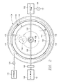
図1および2は、半導体ウェハなどの被加工物の上にプラズマ強化物理蒸着を実施するための、プラズマリアクタを図示している。真空チャンバ100が、円筒形の側壁102、天井104および床106によって取り囲まれる。チャンバ100内の被加工物の支持ペデスタル108が、チャンバ100内のリフト組立体110に保持され、天井104に面する被加工物の支持面108aを有する。支持面108aの上に、半導体ウェハ112などの被加工物を保持することができる。スパッタターゲット114が天井104の内面に保持され、ペデスタル108の支持面108aに面する主面114aを有する。処理領域116が、支持面108aとターゲットの主面114aとの間に画定される。環状のセラミックスペーサ118が、スパッタターゲット114の側縁部114bを囲む。処理領域116を囲む環状の閉じ込め用スカート120が、軸方向にセラミックスペーサ118から、支持ペデスタル108の頂部周縁108bに延びる。間隔を置いた位置にある側壁102を貫通して延びるガス注入ノズル122が、中空のガス分配リング124に結合される。プロセスガス源126が、プロセスガスを、質量流量制御器または弁128を通してガス分配リング124に供給する。真空ポンプ130が、床106を貫通する通路132を通してチャンバ100に結合される。真空制御弁133が、チャンバ圧力を制御する。
1 and 2 illustrate a plasma reactor for performing plasma enhanced physical vapor deposition on a workpiece such as a semiconductor wafer. A
ウェハ支持ペデスタル108は、内部電極134を含むことができる。ペデスタル108が静電チャックを組み入れる場合には、制御可能なD.C.電圧源135をペデスタルの内部電極134に接続することができる。ウェハ112の表面におけるイオンエネルギーを制御するために、低周波のRFバイアス電力発生器136を、RFインピーダンス整合部137を通して電極134に接続することができる。さらに、中周波または高周波のRFバイアス電力発生器138を、インピーダンス整合部139を通して電極134に接続することができる。
The
天井104の上に重なるエンクロージャ140が、マグネトロン組立体142を収容する。マグネトロン組立体142は、半径方向のアーム146に支持された磁石144、およびアーム146を支持する軸方向のスピンドル148を含む。半径方向のアーム146は、別個に関節でつながるアーム部分146a、146bを有する。回転アクチュエータ150がスピンドル148を回転させ、磁石144に天井104の上で軌道回転運動を行わせる。エンクロージャ140は、エンクロージャの側壁152およびエンクロージャの蓋154を含む。蓋は中央の円形開口部156を有し、その開口部156を通って、スピンドル148は、半径方向のアーム146とエンクロージャ140の外部の回転アクチュエータ150との間に延びる。
An
RF源電力のターゲット114への印加時に、(2つの起こりうる例として)供給源の電力をチャンバの天井104上の軸を外れた点、またはハウジングの蓋154上の軸を外れた点に結合することによって、プラズマの変動の問題が生じる。RF電力分布は必ず印加点に集中し、方位が不均一なRF電力分布をもたらす。磁石144がRF電力の印加点と整列した回転の地点を通過すると、プラズマに結合された電力が一時的にピークに達し、本明細書においてこれまでに論じたプロセスの変動をもたらす。
Upon application of RF source power to the
そうしたRF電力の非対称分布を回避するために、ハウジング140の頂部に対称軸と同心の対称な導体を設け、RF電力およびDC電力をターゲット114に印加する。具体的には、スピンドル148を囲む導電性中空シリンダ158が、円形開口部156の縁部から、エンクロージャ140から離れるように延びる。RF接続ロッド160が、中空シリンダ158から半径方向外側に延びる。RFインピーダンス整合部162が、RF接続ロッド160の外側端部に結合される。RF電力発生器164が、RFインピーダンス整合部162に結合される。DC接続ロッド166が、中空シリンダ158から半径方向外側へ、RF接続ロッド160と反対の方向に延びる。DC電力源168が、DC接続ロッド166の外側端部に結合される。DC接続ロッド166は、DC電力供給部168のRF遮断フィルタ169に接続することができる。
In order to avoid such an asymmetric distribution of RF power, a symmetrical conductor concentric with the axis of symmetry is provided at the top of the
中空シリンダ158、接続ロッド160、166、エンクロージャ140および天井104は、例えばアルミニウムなどの非磁性の導電性材料で形成される。接続ロッド160、166およびシリンダ158は、高導電性の電流路を提供するように銅で形成することができる。発生器164からのRF電流は、エンクロージャ140の周縁部の周りの均一な分布、およびターゲット114への均一な印加のために、中空シリンダ158の周りを円の形で流れる。DC源168からのDC電流は、エンクロージャ140の周縁部の周りの均一な分布、およびターゲット114への均一な印加のために、中空シリンダ158の周りを円の形で流れる。ターゲット114は通常、被加工物112の上に堆積される金属性の化学種である。
The
図3は、アルミニウムのエンクロージャ140の拡大図である。エンクロージャ140は、エンクロージャ140と共形の接地されたRF遮蔽体170によって囲まれる。接地された遮蔽体170は、円筒形の側壁172、およびシリンダ158がそれを通って延びる円形通路176を有する環状の頂部174を含む。接地された遮蔽体はさらに、中空シリンダ158と同軸である円筒形の被覆体178を含む。接地された遮蔽体170は、例えばアルミニウムまたは銅などの非磁性金属で形成することができる。遮蔽体170およびエンクロージャ140は、絶縁空間180によって隔離される。一実施形態における空間180は、低誘電率を有する誘電体材料で充たされる。適切な材料の一例は、G−10プラスチックなどのプラスチックである。図4は、空間180が主に空気で充たされ、いくつかの小さいスペーサ182によって維持される実施形態を示している。スペーサ182は、G−10プラスチックなどの誘電体材料で形成することができる。空間180の誘電率を最小限に抑えることによって、寄生容量が最小限に抑えられる。例えばスペーサ182が、空間180の体積の極めて小さい割合を占め、空間180の残りが、空気など最小限の誘電率の物質で充たされるようにすることができる。空間180を横断するギャップ距離Dを大きくすることによって、寄生容量がさらに最小限に抑えられる。一実施形態において、接続ロッド160、166は、接地された遮蔽体170の円筒形の被覆体178中のそれぞれの開口部184を貫通することができる。開口部184に環状の絶縁リング186を挿入して、各ロッド160、166と各開口部184それぞれとの間に絶縁体を設けることができる。
FIG. 3 is an enlarged view of the
空間180のギャップ距離Dは、ギャップを横切る電場が、空間180の誘電体材料(例えば、空気またはプラスチック)の破壊の閾値を超えないように十分大きくする。例えば、絶縁空間180の距離Dの両端に、1100〜1200ボルトの電圧差があってもよい。これは、RF発生器164がハウジング140に平均約500ボルトのRF電圧をかけ、DC源168がハウジング140に約500ボルトのDC電圧をかけ、かつハウジング140を通るRFバイアス電力の戻りが、さらに100ボルトをかけ得る場合に起こることがある。この場合、空間180が空気(破壊の閾値が33,000ボルト/cm)で充たされていれば、必要なギャップ距離Dは最低約0.3mmになる。
The gap distance D of the
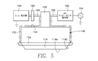
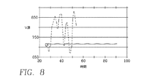
図5は、RF導体ロッド160およびDC導体ロッド166から、シリンダ158の下方へ向かい、天井154を横切り、側壁152の下方へ向かい、天井104を通ってターゲット114に至るRF電流およびDC電流の軸方向の流れを示す、簡略化された図である。図6は、中空シリンダ158の周りのDC電流の円形の流れ、およびハウジングの蓋154上の半径方向のDC電流の流れを示す、図5に対応する1つの平面図である。図7は、中空シリンダ158の周りのRF電流の円形の流れ、およびハウジングの蓋上の半径方向のRF電流の流れを示す、図5に対応するもう1つの平面図である。中空シリンダ158の周りの円形の電流の流れは、電流分布の円対称の(かつ均一な)分布への変化を容易にする。これは、磁石144の回転によるプラズマの変動を実質的に解消する。この結果は、図8のグラフによって表される比較試験データによって確かめられる。図8のグラフの縦軸は、VHFターゲット源の電力発生器(例えば、図1の実施形態の発生器164)の出力部で測定されたRF電圧に対応し、横軸は時間に対応する。点線の曲線は、RF電力がハウジング140の蓋154上の軸を外れた接続点に印加されるリアクタで得られたデータを表す。点線の曲線に対する最小と最大のRF電圧の間の偏移は、26%超である。実線の曲線は、最小−最大のRF電圧の偏移が0.7%まで劇的に低減される、図1のリアクタの軸上のRF供給で得られるデータを表す。これは、極めて安定したまたは静止状態の挙動に対応しており、以下の改善をもたらす:すなわち、(1)RF発生器およびインピーダンス整合部が、100mT程度の所望される高い圧力領域より上に及ぶ、ずっと広い範囲のチャンバ圧力に対して安定した動作を維持する、(2)プラズマは、ウェハ支持ペデスタルの下に浸透するような周期的な刺激を受けない、(3)破壊もしくはアーキングが解消または低減される、(4)供給源の電力の電圧の変動が低減されることによって効率が高まる、(5)DC電力のアーキング保護回路の誤った警告なしに、DC電力のレベルを最小限に抑えることができる、(6)ウェハの堆積厚さの分布における方位の不均一性を生じることなく、ウェハ−ターゲットのギャップを(例えば5cmまで)低減することができる。
FIG. 5 illustrates the RF and DC current axes from the
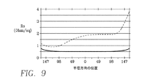
ウェハ上の方位の不均一性の解消というこの最後の結果は、図9のグラフに表される比較試験データによって確かめられる。図9の縦軸は、堆積厚さの指標であるシート抵抗に対応し、横軸は、選択された半径方向の線に沿って得られるウェハ上の半径方向の位置に対応する。図9の点線の曲線は、本明細書でこれまでに述べた、従来のターゲットに対する軸を外れたRF供給によって得られるデータを表す。点線の曲線によって表される方位の不均一性は、25%の最小値と最大値の偏移に対応する。図9の実線の曲線は、最小値と最大値の方位の偏移が5%まで低減される、図1のリアクタの軸上のRF供給によって得られるデータを表す。図9における点線の曲線の非対称性は明らかであり、点線の曲線は、左から右への明確な上向きの傾きを有する。実線の曲線の対称性は明らかであり、図1のリアクタによって方位の均一性が得られることを示している。 This last result of eliminating orientation non-uniformity on the wafer is confirmed by the comparative test data represented in the graph of FIG. The vertical axis in FIG. 9 corresponds to the sheet resistance, which is an indicator of the deposition thickness, and the horizontal axis corresponds to the radial position on the wafer obtained along the selected radial line. The dotted curve in FIG. 9 represents the data obtained from the off-axis RF supply for a conventional target described earlier herein. The orientation non-uniformity represented by the dotted curve corresponds to a minimum and maximum deviation of 25%. The solid curve in FIG. 9 represents the data obtained with the RF feed on the axis of the reactor of FIG. 1 in which the minimum and maximum orientation shifts are reduced to 5%. The asymmetry of the dotted curve in FIG. 9 is obvious, and the dotted curve has a clear upward slope from left to right. The symmetry of the solid curve is obvious, indicating that the reactor of FIG. 1 provides azimuthal uniformity.
前述のものは本発明の実施形態を対象にしているが、本発明の基本的な範囲から逸脱することなく、本発明の他の実施形態およびさらなる実施形態を考案することが可能であり、また本発明の範囲は、後述の特許請求の範囲によって定められる。 While the foregoing is directed to embodiments of the invention, other and further embodiments of the invention may be devised without departing from the basic scope thereof, and The scope of the invention is defined by the claims that follow.
Claims (18)
前記天井の上に重なり、前記天井に面する頂部蓋を有する導電性ハウジングと、
前記ハウジングの中に収容され、回転可能なスピンドル、内側端部が前記スピンドルに結合された半径方向のアーム組立体、および前記半径方向のアーム組立体の外側端部に結合された磁石を含む回転磁石組立体であって、前記ハウジングの前記頂部蓋が中央ポートを有し、前記スピンドルが前記中央ポートを通って軸方向に延びる回転磁石組立体と、
前記スピンドルの前記頂部蓋より上に延びる部分を同軸に囲む、前記頂部蓋上の導電性中空シリンダと、
前記中空シリンダに接続された第1の半径方向内側端部と第1の半径方向外側端部とを有する半径方向のRF接続ロッドであって、前記中空シリンダから前記第1の半径方向外側端部に向かって半径方向外側に延びる半径方向のRF接続ロッドと、
RF発生器およびRFインピーダンス整合部を含むRF電力源であって、前記インピーダンス整合部が、前記半径方向のRF接続ロッドの前記第1の半径方向外側端部に接続されている、RF電力源と、
前記導電性ハウジングと前記導電性中空シリンダの外側を囲む接地された導電性遮蔽エンクロージャであって、前記半径方向のRF接続ロッドは前記導電性遮蔽エンクロージャを貫通し且つ前記導電性遮蔽エンクロージャから絶縁されている、導電性遮蔽エンクロージャと
を備えるプラズマリアクタ。 A reactor chamber comprising a ceiling, a sputter target adjacent to the ceiling, and a wafer support pedestal therein facing the sputter target;
A conductive housing overlying the ceiling and having a top lid facing the ceiling;
Rotating said housed in a housing, comprising a rotatable spindle, the arm assembly radially inner end portion is coupled to the spindle, and the radial direction of the magnet coupled to the outer end of the arm assembly A rotating magnet assembly, wherein the top lid of the housing has a central port and the spindle extends axially through the central port;
A conductive hollow cylinder on the top lid that coaxially surrounds a portion of the spindle extending above the top lid;
A radial RF connecting rod having a first radially inner end and a first radially outer end connected to the hollow cylinder, the first radial outer end from the hollow cylinder A radial RF connecting rod extending radially outward toward
An RF power source including an RF generator and an RF impedance matching portion, wherein the impedance matching portion is connected to the first radially outer end of the radial RF connecting rod; ,
A grounded conductive shielding enclosure surrounding the conductive housing and the conductive hollow cylinder, wherein the radial RF connecting rod penetrates the conductive shielding enclosure and is insulated from the conductive shielding enclosure. A plasma reactor comprising a conductive shielding enclosure.
DC電力供給部およびRF遮断フィルタを含むDC電力源であって、前記RF遮断フィルタが、前記半径方向のDC接続ロッドの前記第2の半径方向外側端部に接続されており、前記半径方向のDC接続ロッドは前記導電性遮蔽エンクロージャを貫通し且つ前記導電性遮蔽エンクロージャから絶縁されている、DC電力源と
をさらに備える請求項1に記載のリアクタ。 A radial DC connecting rod having a second radially inner end and a second radially outer end connected to the hollow cylinder, the first of the radial DC connecting rods from the hollow cylinder. A radial DC connecting rod extending radially outward toward the two radially outer ends;
A DC power source including a DC power supply and an RF cutoff filter, wherein the RF cutoff filter is connected to the second radially outer end of the radial DC connecting rod; The reactor of claim 1, further comprising: a DC power source, wherein a DC connecting rod penetrates the conductive shielding enclosure and is insulated from the conductive shielding enclosure.
前記ウェハ支持ペデスタルに結合されたRFバイアス電力源と
をさらに備える請求項1に記載のリアクタ。 An electrode in the wafer support pedestal;
The reactor of claim 1, further comprising an RF bias power source coupled to the wafer support pedestal.
高周波RF電力発生器、および前記電極に接続された高周波インピーダンス整合部と、
低周波RF電力発生器、および前記電極に接続された低周波インピーダンス整合部と
を備える請求項6に記載のリアクタ。 The RF bias power source is
A high frequency RF power generator, and a high frequency impedance matching unit connected to the electrode;
The reactor of Claim 6 provided with a low frequency RF electric power generator and the low frequency impedance matching part connected to the said electrode.
前記ハウジングを囲む導電性側壁であって、前記ハウジングと該導電性側壁の間に第1のギャップを形成するように前記ハウジングから隔離される導電性側壁と、
前記ハウジングの前記頂部蓋の上に重なる導電性遮蔽蓋であって、前記頂部蓋から第2のギャップによって隔離され、前記頂部蓋と該導電性遮蔽蓋の間に第2のギャップを形成するように前記頂部蓋から隔離される導電性遮蔽蓋と、
前記中空シリンダを囲む導電性スリーブであって、前記中空シリンダと該導電性スリーブの間に第3のギャップを形成するように前記中空シリンダから隔離され、前記第1、第2および第3のギャップが連続空間を形成する導電性スリーブと
を含む請求項1に記載のリアクタ。 The conductive shielding enclosure comprises:
A conductive sidewall surrounding the housing, wherein the conductive sidewall is isolated from the housing to form a first gap between the housing and the conductive sidewall;
A conductive shielding lid overlying the top lid of the housing, separated from the top lid by a second gap, so as to form a second gap between the top lid and the conductive shielding lid; A conductive shielding lid isolated from the top lid;
A conductive sleeve surrounding the hollow cylinder, wherein the first, second and third gaps are isolated from the hollow cylinder to form a third gap between the hollow cylinder and the conductive sleeve; The reactor according to claim 1, comprising a conductive sleeve forming a continuous space.
前記天井の上に重なり、前記天井に面する頂部蓋を有する導電性ハウジングと、
前記ハウジングの中に収容され、回転可能なスピンドル、内側端部が前記スピンドルに結合された半径方向のアーム組立体、および前記半径方向のアーム組立体の外側端部に結合された磁石を含む回転磁石組立体であって、前記ハウジングの前記頂部蓋が中央ポートを有し、前記スピンドルが前記中央ポートを通って軸方向に延びる回転磁石組立体と、
前記スピンドルの前記頂部蓋より上に延びる部分を同軸に囲む、前記頂部蓋上の導電性中空シリンダと、
前記中空シリンダに接続された第1の半径方向内側端部と第1の半径方向外側端部とを有する半径方向のRF接続ロッドであって、前記中空シリンダから前記第1の半径方向外側端部に向かって半径方向外側に延び、RF電力源に接続するように適合された半径方向のRF接続ロッドと、
前記導電性ハウジングと前記導電性中空シリンダの外側を囲む接地された導電性遮蔽エンクロージャであって、前記半径方向のRF接続ロッドは前記導電性遮蔽エンクロージャを貫通し且つ前記導電性遮蔽エンクロージャから絶縁されている、導電性遮蔽エンクロージャと
を備えるプラズマリアクタ。 A plasma reactor having a ceiling, a sputter target adjacent to the ceiling, and an RF supply system, the RF supply system comprising:
A conductive housing overlying the ceiling and having a top lid facing the ceiling;
Rotating said housed in a housing, comprising a rotatable spindle, the arm assembly radially inner end portion is coupled to the spindle, and the radial direction of the magnet coupled to the outer end of the arm assembly A rotating magnet assembly, wherein the top lid of the housing has a central port and the spindle extends axially through the central port;
A conductive hollow cylinder on the top lid that coaxially surrounds a portion of the spindle extending above the top lid;
A radial RF connecting rod having a first radially inner end and a first radially outer end connected to the hollow cylinder, the first radial outer end from the hollow cylinder A radial RF connecting rod that extends radially outward towards and adapted to connect to an RF power source;
A grounded conductive shielding enclosure surrounding the conductive housing and the conductive hollow cylinder, wherein the radial RF connecting rod penetrates the conductive shielding enclosure and is insulated from the conductive shielding enclosure. A plasma reactor comprising a conductive shielding enclosure.
前記ハウジングを囲む導電性側壁であって、前記ハウジングと該導電性側壁の間に第1のギャップを形成するように前記ハウジングから隔離される導電性側壁と、
前記ハウジングの前記頂部蓋の上に重なる導電性遮蔽蓋であって、前記頂部蓋から第2のギャップによって隔離され、前記頂部蓋と該導電性遮蔽蓋の間に第2のギャップを形成するように前記頂部蓋から隔離される導電性遮蔽蓋と、
前記中空シリンダを囲む導電性スリーブであって、前記中空シリンダと該導電性スリーブの間に第3のギャップを形成するように前記中空シリンダから隔離され、前記第1、第2および第3のギャップが連続空間を形成する導電性スリーブと
を含む請求項11に記載のリアクタ。 The conductive shielding enclosure comprises:
A conductive sidewall surrounding the housing, wherein the conductive sidewall is isolated from the housing to form a first gap between the housing and the conductive sidewall;
A conductive shielding lid overlying the top lid of the housing, separated from the top lid by a second gap, so as to form a second gap between the top lid and the conductive shielding lid; A conductive shielding lid isolated from the top lid;
A conductive sleeve surrounding the hollow cylinder, wherein the first, second and third gaps are isolated from the hollow cylinder to form a third gap between the hollow cylinder and the conductive sleeve; The reactor according to claim 11, comprising a conductive sleeve forming a continuous space.
Applications Claiming Priority (3)
| Application Number | Priority Date | Filing Date | Title |
|---|---|---|---|
| US12/253,603 | 2008-10-17 | ||
| US12/253,603 US8070925B2 (en) | 2008-10-17 | 2008-10-17 | Physical vapor deposition reactor with circularly symmetric RF feed and DC feed to the sputter target |
| PCT/US2009/059335 WO2010045037A2 (en) | 2008-10-17 | 2009-10-02 | Physical vapor deposition reactor with circularly symmetric rf feed and dc feed to the sputter target |
Publications (3)
| Publication Number | Publication Date |
|---|---|
| JP2012505968A JP2012505968A (en) | 2012-03-08 |
| JP2012505968A5 JP2012505968A5 (en) | 2013-04-11 |
| JP5345221B2 true JP5345221B2 (en) | 2013-11-20 |
Family
ID=42107132
Family Applications (1)
| Application Number | Title | Priority Date | Filing Date |
|---|---|---|---|
| JP2011532144A Active JP5345221B2 (en) | 2008-10-17 | 2009-10-02 | Physical vapor deposition reactor using circularly symmetric RF and DC feed to a sputter target |
Country Status (6)
| Country | Link |
|---|---|
| US (1) | US8070925B2 (en) |
| JP (1) | JP5345221B2 (en) |
| KR (1) | KR101284787B1 (en) |
| CN (1) | CN102203908B (en) |
| TW (1) | TWI388001B (en) |
| WO (1) | WO2010045037A2 (en) |
Families Citing this family (70)
| Publication number | Priority date | Publication date | Assignee | Title |
|---|---|---|---|---|
| CN102439697B (en) * | 2009-04-03 | 2015-08-19 | 应用材料公司 | High pressure RF-DC sputters and improves the film uniformity of this technique and the method for step coverage rate |
| US9012766B2 (en) | 2009-11-12 | 2015-04-21 | Silevo, Inc. | Aluminum grid as backside conductor on epitaxial silicon thin film solar cells |
| US8795488B2 (en) | 2010-03-31 | 2014-08-05 | Applied Materials, Inc. | Apparatus for physical vapor deposition having centrally fed RF energy |
| US8795487B2 (en) | 2010-03-31 | 2014-08-05 | Applied Materials, Inc. | Physical vapor deposition chamber with rotating magnet assembly and centrally fed RF power |
| US9214576B2 (en) | 2010-06-09 | 2015-12-15 | Solarcity Corporation | Transparent conducting oxide for photovoltaic devices |
| TWI554630B (en) * | 2010-07-02 | 2016-10-21 | 應用材料股份有限公司 | Deposition apparatus and methods to reduce deposition asymmetry |
| US9773928B2 (en) | 2010-09-10 | 2017-09-26 | Tesla, Inc. | Solar cell with electroplated metal grid |
| US8563428B2 (en) * | 2010-09-17 | 2013-10-22 | Applied Materials, Inc. | Methods for depositing metal in high aspect ratio features |
| US9800053B2 (en) | 2010-10-08 | 2017-10-24 | Tesla, Inc. | Solar panels with integrated cell-level MPPT devices |
| US20120097104A1 (en) * | 2010-10-20 | 2012-04-26 | COMET Technologies USA, Inc. | Rf impedance matching network with secondary dc input |
| US8491759B2 (en) * | 2010-10-20 | 2013-07-23 | COMET Technologies USA, Inc. | RF impedance matching network with secondary frequency and sub-harmonic variant |
| US9054256B2 (en) | 2011-06-02 | 2015-06-09 | Solarcity Corporation | Tunneling-junction solar cell with copper grid for concentrated photovoltaic application |
| US9508530B2 (en) | 2011-11-21 | 2016-11-29 | Lam Research Corporation | Plasma processing chamber with flexible symmetric RF return strap |
| US10586686B2 (en) | 2011-11-22 | 2020-03-10 | Law Research Corporation | Peripheral RF feed and symmetric RF return for symmetric RF delivery |
| US9263240B2 (en) | 2011-11-22 | 2016-02-16 | Lam Research Corporation | Dual zone temperature control of upper electrodes |
| US9396908B2 (en) | 2011-11-22 | 2016-07-19 | Lam Research Corporation | Systems and methods for controlling a plasma edge region |
| WO2013078098A1 (en) * | 2011-11-23 | 2013-05-30 | Lam Research Corporation | Multi zone gas injection upper electrode system |
| WO2013078346A1 (en) * | 2011-11-23 | 2013-05-30 | Lam Research Corporation | Peripheral rf feed and symmetric rf return for symmetric rf delivery |
| US9255322B2 (en) * | 2012-03-30 | 2016-02-09 | Applied Materials, Inc. | Substrate processing system having symmetric RF distribution and return paths |
| MX351564B (en) | 2012-10-04 | 2017-10-18 | Solarcity Corp | Photovoltaic devices with electroplated metal grids. |
| FR2996679A1 (en) * | 2012-10-09 | 2014-04-11 | St Microelectronics Crolles 2 | METHOD FOR DEPOSITING A LOW-DIFFUSED TIALN LAYER AND ISOLATED GRID COMPRISING SUCH A LAYER |
| US9865754B2 (en) | 2012-10-10 | 2018-01-09 | Tesla, Inc. | Hole collectors for silicon photovoltaic cells |
| US9265184B2 (en) * | 2012-11-20 | 2016-02-16 | ETS-Lindgren Inc. | Fluid conduit through RF shield |
| CN103849848B (en) * | 2012-11-28 | 2016-08-31 | 北京北方微电子基地设备工艺研究中心有限责任公司 | Physical vapor deposition device |
| US9281436B2 (en) | 2012-12-28 | 2016-03-08 | Solarcity Corporation | Radio-frequency sputtering system with rotary target for fabricating solar cells |
| WO2014110520A1 (en) | 2013-01-11 | 2014-07-17 | Silevo, Inc. | Module fabrication of solar cells with low resistivity electrodes |
| US10074755B2 (en) | 2013-01-11 | 2018-09-11 | Tesla, Inc. | High efficiency solar panel |
| US9412884B2 (en) | 2013-01-11 | 2016-08-09 | Solarcity Corporation | Module fabrication of solar cells with low resistivity electrodes |
| US9580795B2 (en) * | 2013-03-05 | 2017-02-28 | Applied Materials, Inc. | Sputter source for use in a semiconductor process chamber |
| US9593410B2 (en) * | 2013-03-05 | 2017-03-14 | Applied Materials, Inc. | Methods and apparatus for stable substrate processing with multiple RF power supplies |
| KR101326386B1 (en) * | 2013-05-03 | 2013-11-11 | 이천용 | Semiconductor process chamber |
| US9624595B2 (en) | 2013-05-24 | 2017-04-18 | Solarcity Corporation | Electroplating apparatus with improved throughput |
| US10309012B2 (en) | 2014-07-03 | 2019-06-04 | Tesla, Inc. | Wafer carrier for reducing contamination from carbon particles and outgassing |
| US10804083B2 (en) * | 2014-07-09 | 2020-10-13 | Taiwan Semiconductor Manufacturing Co., Ltd. | Cathode assembly, physical vapor deposition system, and method for physical vapor deposition |
| US9899546B2 (en) | 2014-12-05 | 2018-02-20 | Tesla, Inc. | Photovoltaic cells with electrodes adapted to house conductive paste |
| US9947822B2 (en) | 2015-02-02 | 2018-04-17 | Tesla, Inc. | Bifacial photovoltaic module using heterojunction solar cells |
| US9761744B2 (en) | 2015-10-22 | 2017-09-12 | Tesla, Inc. | System and method for manufacturing photovoltaic structures with a metal seed layer |
| US9842956B2 (en) | 2015-12-21 | 2017-12-12 | Tesla, Inc. | System and method for mass-production of high-efficiency photovoltaic structures |
| US9496429B1 (en) | 2015-12-30 | 2016-11-15 | Solarcity Corporation | System and method for tin plating metal electrodes |
| US10115838B2 (en) | 2016-04-19 | 2018-10-30 | Tesla, Inc. | Photovoltaic structures with interlocking busbars |
| USD836572S1 (en) | 2016-09-30 | 2018-12-25 | Applied Materials, Inc. | Target profile for a physical vapor deposition chamber target |
| US20180294139A1 (en) * | 2017-04-07 | 2018-10-11 | Applied Materials, Inc. | Gas phase particle reduction in pecvd chamber |
| CN109207942B (en) * | 2017-07-04 | 2023-08-18 | 北京北方华创微电子装备有限公司 | Metal film deposition method and metal film deposition equipment |
| CN107475677A (en) * | 2017-08-18 | 2017-12-15 | 嘉兴申宁精密科技有限公司 | A kind of device using physical gas-phase deposition sputter coating |
| US10672919B2 (en) | 2017-09-19 | 2020-06-02 | Tesla, Inc. | Moisture-resistant solar cells for solar roof tiles |
| USD851613S1 (en) | 2017-10-05 | 2019-06-18 | Applied Materials, Inc. | Target profile for a physical vapor deposition chamber target |
| KR102644960B1 (en) | 2017-11-29 | 2024-03-07 | 코멧 테크놀로지스 유에스에이, 인크. | Retuning for impedance matching network control |
| USD868124S1 (en) * | 2017-12-11 | 2019-11-26 | Applied Materials, Inc. | Target profile for a physical vapor deposition chamber target |
| US11190128B2 (en) | 2018-02-27 | 2021-11-30 | Tesla, Inc. | Parallel-connected solar roof tile modules |
| USD877101S1 (en) | 2018-03-09 | 2020-03-03 | Applied Materials, Inc. | Target profile for a physical vapor deposition chamber target |
| US11527385B2 (en) | 2021-04-29 | 2022-12-13 | COMET Technologies USA, Inc. | Systems and methods for calibrating capacitors of matching networks |
| US11114279B2 (en) | 2019-06-28 | 2021-09-07 | COMET Technologies USA, Inc. | Arc suppression device for plasma processing equipment |
| US11107661B2 (en) | 2019-07-09 | 2021-08-31 | COMET Technologies USA, Inc. | Hybrid matching network topology |
| US11596309B2 (en) | 2019-07-09 | 2023-03-07 | COMET Technologies USA, Inc. | Hybrid matching network topology |
| USD908645S1 (en) | 2019-08-26 | 2021-01-26 | Applied Materials, Inc. | Sputtering target for a physical vapor deposition chamber |
| US11670488B2 (en) | 2020-01-10 | 2023-06-06 | COMET Technologies USA, Inc. | Fast arc detecting match network |
| US11887820B2 (en) | 2020-01-10 | 2024-01-30 | COMET Technologies USA, Inc. | Sector shunts for plasma-based wafer processing systems |
| US11830708B2 (en) | 2020-01-10 | 2023-11-28 | COMET Technologies USA, Inc. | Inductive broad-band sensors for electromagnetic waves |
| US11521832B2 (en) | 2020-01-10 | 2022-12-06 | COMET Technologies USA, Inc. | Uniformity control for radio frequency plasma processing systems |
| US11961711B2 (en) | 2020-01-20 | 2024-04-16 | COMET Technologies USA, Inc. | Radio frequency match network and generator |
| US11605527B2 (en) | 2020-01-20 | 2023-03-14 | COMET Technologies USA, Inc. | Pulsing control match network |
| WO2021148195A1 (en) * | 2020-01-24 | 2021-07-29 | Evatec Ag | Phase shift controlled sputter system and process |
| USD937329S1 (en) | 2020-03-23 | 2021-11-30 | Applied Materials, Inc. | Sputter target for a physical vapor deposition chamber |
| US11373844B2 (en) | 2020-09-28 | 2022-06-28 | COMET Technologies USA, Inc. | Systems and methods for repetitive tuning of matching networks |
| USD940765S1 (en) | 2020-12-02 | 2022-01-11 | Applied Materials, Inc. | Target profile for a physical vapor deposition chamber target |
| USD1007449S1 (en) | 2021-05-07 | 2023-12-12 | Applied Materials, Inc. | Target profile for a physical vapor deposition chamber target |
| US11761078B2 (en) | 2021-05-25 | 2023-09-19 | Applied Materials, Inc. | Methods and apparatus for processing a substrate |
| US11923175B2 (en) | 2021-07-28 | 2024-03-05 | COMET Technologies USA, Inc. | Systems and methods for variable gain tuning of matching networks |
| CN117813680A (en) * | 2021-08-12 | 2024-04-02 | 朗姆研究公司 | Process module chamber providing symmetrical RF return path |
| US11657980B1 (en) | 2022-05-09 | 2023-05-23 | COMET Technologies USA, Inc. | Dielectric fluid variable capacitor |
Family Cites Families (25)
| Publication number | Priority date | Publication date | Assignee | Title |
|---|---|---|---|---|
| US15510A (en) * | 1856-08-12 | John w | ||
| US291717A (en) * | 1884-01-08 | John geeives | ||
| US97945A (en) * | 1869-12-14 | Improved mechanism for driving cotton-gins | ||
| US211659A (en) * | 1879-01-28 | Improvement in spring bed-bottoms | ||
| US231625A (en) * | 1880-08-24 | Damper for cooking-stoves | ||
| US268816A (en) * | 1882-12-12 | Rotary differential force-pump | ||
| US215279A (en) * | 1879-05-13 | Improvement in ventilators | ||
| US15509A (en) * | 1856-08-12 | Odometeb | ||
| US72604A (en) * | 1867-12-24 | James cole | ||
| JPH0669026B2 (en) * | 1985-09-26 | 1994-08-31 | 株式会社芝浦製作所 | Semiconductor processing equipment |
| US5482610A (en) * | 1991-11-14 | 1996-01-09 | Leybold Aktiengesellschaft | Cathode for coating a substrate |
| FR2743246B1 (en) * | 1995-12-29 | 1998-01-23 | Thomson Broadcast Systems | METHOD AND DEVICE FOR COMPRESSING DIGITAL DATA |
| US6375810B2 (en) * | 1997-08-07 | 2002-04-23 | Applied Materials, Inc. | Plasma vapor deposition with coil sputtering |
| JP4435896B2 (en) * | 1999-03-17 | 2010-03-24 | キヤノンアネルバ株式会社 | High frequency sputtering apparatus and thin film forming method |
| US6900596B2 (en) * | 2002-07-09 | 2005-05-31 | Applied Materials, Inc. | Capacitively coupled plasma reactor with uniform radial distribution of plasma |
| EP1254970A1 (en) * | 2001-05-03 | 2002-11-06 | Unaxis Balzers Aktiengesellschaft | Magnetron sputter source having mosaic target |
| US20050022736A1 (en) * | 2003-07-29 | 2005-02-03 | Lam Research Inc., A Delaware Corporation | Method for balancing return currents in plasma processing apparatus |
| JP4040607B2 (en) * | 2004-06-14 | 2008-01-30 | 芝浦メカトロニクス株式会社 | Sputtering apparatus and method, and sputtering control program |
| US20060172536A1 (en) * | 2005-02-03 | 2006-08-03 | Brown Karl M | Apparatus for plasma-enhanced physical vapor deposition of copper with RF source power applied through the workpiece |
| JP4537899B2 (en) * | 2005-07-05 | 2010-09-08 | 富士通セミコンダクター株式会社 | Film-forming method and semiconductor device manufacturing method |
| JP2008047762A (en) * | 2006-08-18 | 2008-02-28 | Showa Denko Kk | Group iii nitride compound semiconductor light emitting element, process for fabricating the same, and lamp |
| CN100576438C (en) * | 2006-11-15 | 2009-12-30 | 应用材料股份有限公司 | Strengthen constraint baffle plate and flow equalizer that magnetic control system plasma radial distributes |
| US20080121516A1 (en) * | 2006-11-29 | 2008-05-29 | Jaydeep Sarkar | Method and apparatus for treating sputtering target to reduce burn-in time and sputtering targets made thereby |
| US8992741B2 (en) * | 2008-08-08 | 2015-03-31 | Applied Materials, Inc. | Method for ultra-uniform sputter deposition using simultaneous RF and DC power on target |
| JP2009052145A (en) * | 2008-10-10 | 2009-03-12 | Canon Anelva Corp | Sputtering system |
-
2008
- 2008-10-17 US US12/253,603 patent/US8070925B2/en active Active
-
2009
- 2009-10-02 CN CN2009801439352A patent/CN102203908B/en not_active Expired - Fee Related
- 2009-10-02 JP JP2011532144A patent/JP5345221B2/en active Active
- 2009-10-02 WO PCT/US2009/059335 patent/WO2010045037A2/en active Application Filing
- 2009-10-02 KR KR1020117011118A patent/KR101284787B1/en active IP Right Grant
- 2009-10-14 TW TW098134829A patent/TWI388001B/en active
Also Published As
| Publication number | Publication date |
|---|---|
| CN102203908B (en) | 2013-10-02 |
| KR20110084948A (en) | 2011-07-26 |
| KR101284787B1 (en) | 2013-07-10 |
| TWI388001B (en) | 2013-03-01 |
| US8070925B2 (en) | 2011-12-06 |
| JP2012505968A (en) | 2012-03-08 |
| WO2010045037A2 (en) | 2010-04-22 |
| WO2010045037A3 (en) | 2010-07-01 |
| WO2010045037A8 (en) | 2011-05-26 |
| CN102203908A (en) | 2011-09-28 |
| US20100096261A1 (en) | 2010-04-22 |
| TW201030811A (en) | 2010-08-16 |
Similar Documents
| Publication | Publication Date | Title |
|---|---|---|
| JP5345221B2 (en) | Physical vapor deposition reactor using circularly symmetric RF and DC feed to a sputter target | |
| JP6238288B2 (en) | Deposition apparatus and method for reducing deposition asymmetry | |
| US10276348B2 (en) | Methods and apparatus for a hybrid capacitively-coupled and an inductively-coupled plasma processing system | |
| KR101376671B1 (en) | physical vapor deposition reactor | |
| US5605637A (en) | Adjustable dc bias control in a plasma reactor | |
| KR101687565B1 (en) | Plasma processing apparatus and plasma processing method | |
| US6462482B1 (en) | Plasma processing system for sputter deposition applications | |
| JP5277473B2 (en) | Plasma processing equipment | |
| US8486242B2 (en) | Deposition apparatus and methods to reduce deposition asymmetry | |
| KR20060090745A (en) | Side rf coil and side heater for plasma processing apparatus | |
| WO1998048444A1 (en) | Method and apparatus for ionized sputtering of materials | |
| US6210539B1 (en) | Method and apparatus for producing a uniform density plasma above a substrate | |
| JP4588212B2 (en) | Sputtering apparatus comprising a coil having overlapping ends | |
| JP2002520492A (en) | Feedthrough overlapping coil | |
| WO2020070482A1 (en) | Electrode array | |
| US6077402A (en) | Central coil design for ionized metal plasma deposition | |
| US20030116432A1 (en) | Adjustable throw reactor | |
| KR101239776B1 (en) | A physical vapor deposition plasma reactor with rf source power applied to the target | |
| US6409890B1 (en) | Method and apparatus for forming a uniform layer on a workpiece during sputtering | |
| JP2011017088A (en) | Plasma treatment apparatus for applying sputtering film deposition |
Legal Events
| Date | Code | Title | Description |
|---|---|---|---|
| A621 | Written request for application examination |
Free format text: JAPANESE INTERMEDIATE CODE: A621 Effective date: 20121001 |
|
| A521 | Request for written amendment filed |
Free format text: JAPANESE INTERMEDIATE CODE: A523 Effective date: 20130225 |
|
| A871 | Explanation of circumstances concerning accelerated examination |
Free format text: JAPANESE INTERMEDIATE CODE: A871 Effective date: 20130225 |
|
| A975 | Report on accelerated examination |
Free format text: JAPANESE INTERMEDIATE CODE: A971005 Effective date: 20130326 |
|
| A131 | Notification of reasons for refusal |
Free format text: JAPANESE INTERMEDIATE CODE: A131 Effective date: 20130402 |
|
| A521 | Request for written amendment filed |
Free format text: JAPANESE INTERMEDIATE CODE: A523 Effective date: 20130617 |
|
| TRDD | Decision of grant or rejection written | ||
| A01 | Written decision to grant a patent or to grant a registration (utility model) |
Free format text: JAPANESE INTERMEDIATE CODE: A01 Effective date: 20130716 |
|
| A61 | First payment of annual fees (during grant procedure) |
Free format text: JAPANESE INTERMEDIATE CODE: A61 Effective date: 20130813 |
|
| R150 | Certificate of patent or registration of utility model |
Ref document number: 5345221 Country of ref document: JP Free format text: JAPANESE INTERMEDIATE CODE: R150 Free format text: JAPANESE INTERMEDIATE CODE: R150 |
|
| R250 | Receipt of annual fees |
Free format text: JAPANESE INTERMEDIATE CODE: R250 |
|
| R250 | Receipt of annual fees |
Free format text: JAPANESE INTERMEDIATE CODE: R250 |
|
| R250 | Receipt of annual fees |
Free format text: JAPANESE INTERMEDIATE CODE: R250 |
|
| R250 | Receipt of annual fees |
Free format text: JAPANESE INTERMEDIATE CODE: R250 |
|
| R250 | Receipt of annual fees |
Free format text: JAPANESE INTERMEDIATE CODE: R250 |
|
| R250 | Receipt of annual fees |
Free format text: JAPANESE INTERMEDIATE CODE: R250 |
|
| R250 | Receipt of annual fees |
Free format text: JAPANESE INTERMEDIATE CODE: R250 |