JP5337804B2 - Self-adaptive frequency interpolator for use with multi-carrier receivers. - Google Patents
Self-adaptive frequency interpolator for use with multi-carrier receivers. Download PDFInfo
- Publication number
- JP5337804B2 JP5337804B2 JP2010526386A JP2010526386A JP5337804B2 JP 5337804 B2 JP5337804 B2 JP 5337804B2 JP 2010526386 A JP2010526386 A JP 2010526386A JP 2010526386 A JP2010526386 A JP 2010526386A JP 5337804 B2 JP5337804 B2 JP 5337804B2
- Authority
- JP
- Japan
- Prior art keywords
- signal
- determined
- function
- receiver
- interpolator
- Prior art date
- Legal status (The legal status is an assumption and is not a legal conclusion. Google has not performed a legal analysis and makes no representation as to the accuracy of the status listed.)
- Expired - Fee Related
Links
Images


Classifications
-
- H—ELECTRICITY
- H04—ELECTRIC COMMUNICATION TECHNIQUE
- H04L—TRANSMISSION OF DIGITAL INFORMATION, e.g. TELEGRAPHIC COMMUNICATION
- H04L25/00—Baseband systems
- H04L25/02—Details ; arrangements for supplying electrical power along data transmission lines
- H04L25/0202—Channel estimation
- H04L25/0224—Channel estimation using sounding signals
- H04L25/0228—Channel estimation using sounding signals with direct estimation from sounding signals
- H04L25/023—Channel estimation using sounding signals with direct estimation from sounding signals with extension to other symbols
- H04L25/0232—Channel estimation using sounding signals with direct estimation from sounding signals with extension to other symbols by interpolation between sounding signals
-
- H—ELECTRICITY
- H04—ELECTRIC COMMUNICATION TECHNIQUE
- H04L—TRANSMISSION OF DIGITAL INFORMATION, e.g. TELEGRAPHIC COMMUNICATION
- H04L25/00—Baseband systems
- H04L25/02—Details ; arrangements for supplying electrical power along data transmission lines
- H04L25/0202—Channel estimation
- H04L25/0204—Channel estimation of multiple channels
-
- H—ELECTRICITY
- H04—ELECTRIC COMMUNICATION TECHNIQUE
- H04L—TRANSMISSION OF DIGITAL INFORMATION, e.g. TELEGRAPHIC COMMUNICATION
- H04L25/00—Baseband systems
- H04L25/02—Details ; arrangements for supplying electrical power along data transmission lines
- H04L25/0202—Channel estimation
- H04L25/0212—Channel estimation of impulse response
- H04L25/0216—Channel estimation of impulse response with estimation of channel length
-
- H—ELECTRICITY
- H04—ELECTRIC COMMUNICATION TECHNIQUE
- H04L—TRANSMISSION OF DIGITAL INFORMATION, e.g. TELEGRAPHIC COMMUNICATION
- H04L27/00—Modulated-carrier systems
- H04L27/26—Systems using multi-frequency codes
- H04L27/2601—Multicarrier modulation systems
- H04L27/2647—Arrangements specific to the receiver only
Description
本発明は通信システムに関し、特に、例えば、地上放送、セルラー、ワイヤレス−フィデリティー(Wi−Fi)、衛星放送等のワイヤレスシステムに関する。 The present invention relates to a communication system, and more particularly to a wireless system such as terrestrial broadcasting, cellular, wireless-fidelity (Wi-Fi), satellite broadcasting, and the like.
地上デジタル放送(DVB−T)(例えば、ETSI EN 300 744 V 1.4.1 (2001−01)、デジタル放送(DVB)、地上波デジタル・テレビジョンのフレーム構造、チャネル符号化、及び変調)は、世界の4種類のディジタルテレビ(DTV)放送規格のうちの1つであり、DVB−HはDVB−Tに基づく携帯用アプリケーションの規格である(本明細書においてはDVB−T/Hとも称する)。DVB−Tは直交周波数分割多重(OFDM)技術を利用している、すなわち、DVB−Tは、直交した低シンボルレートの副搬送波を多く含むマルチ搬送波伝送の形態を使用する。 Terrestrial digital broadcasting (DVB-T) (for example, ETSI EN 300 744 V 1.4.1 (2001-01), digital broadcasting (DVB), terrestrial digital television frame structure, channel coding, and modulation) Is one of the four types of digital television (DTV) broadcasting standards in the world, and DVB-H is a portable application standard based on DVB-T (in this specification, it is also referred to as DVB-T / H). Called). DVB-T utilizes orthogonal frequency division multiplexing (OFDM) technology, ie, DVB-T uses a form of multi-carrier transmission that includes many orthogonal low symbol rate subcarriers.
OFDM技術によって、高データレートのワイヤレス通信が提供される。OFDMベースの通信システムにおいて、受信機がすべての副搬送波のチャンネル状態情報を決定することは、重要である。チャンネル状態情報は、データを信頼性良く送信する副搬送波の各々の信用の度合いを表す。 OFDM technology provides high data rate wireless communications. In an OFDM-based communication system, it is important for the receiver to determine channel state information for all subcarriers. The channel state information represents the degree of trust of each subcarrier that transmits data with high reliability.
従来のチャンネル推定装置が図1及び図2に示されている。DVB−Tにおいて、2つの動作モードが存在する。すなわち、2048副搬送波に対応する2Kモード及び8192副搬送波の使用に対応する8Kモードである。この例において、受話器は8Kモードで動作していることが想定されている。2Kモードにおける動作は同様であるので、本明細書には説明していない。図1のチャンネル推定装置は高速フーリエ変換(FFT)要素105、搬送波位相誤差(CPE)除去要素110、及びチャネル推定・均等化(CHE)要素115を含む。FFT要素105は受信されたベースバンド信号104を処理する。後者は、選択されたRFチャネルに調節された例えばチューナ(図示せず)によって出力される。FFT要素105は受信されたベースバンド信号104を時間領域から周波数領域に変換し、FFT出力信号106を出力する。尚、FFT出力信号106は同相且つ直交成分を有する複素信号に相当する。通常、FFT要素105は、当技術分野で知られているようにバタフライ演算を実行し、並び換えられた出力データ(8k作動モードにおける8192複素サンプル)を出力する。そういうものとして、FFT要素105は、スペクトルのシフトをさらに実行して、FFT出力データを再編成し又はシフトせしめて、上述のDVB−T規格に基づく副搬送波のロケーションを満たす。CPE除去要素110はFFT出力信号106を処理して、搬送波の位相誤差の全てをも取り除き、CPE補正信号111をCHE要素115に出力する。CHE要素115はCPE補正信号111を処理する。これは、(a)CSI信号117を出力するためにチャンネル状態情報(CSI)を決定し、及び(b)受信されたベースバンドの信号を均等化して、均等化された信号116を出力するために、あらゆる伝送チャネルのひずみを補完するためである。当技術分野で知られているように、CSI信号117は、復号化の際に使用するためのビットメトリックスを取得するのに使用され得る(図1に示されていない)。均等化された信号116は受信機によってさらに処理されて、例えば、そこに伝送されたコンテンツ(音声、映像等)(図1には示されていない)を復元する。
A conventional channel estimation apparatus is shown in FIGS. There are two modes of operation in DVB-T. That is, the 2K mode corresponding to the 2048 subcarrier and the 8K mode corresponding to the use of the 8192 subcarrier. In this example, it is assumed that the handset is operating in 8K mode. Since the operation in the 2K mode is the same, it is not described herein. The channel estimation apparatus of FIG. 1 includes a fast Fourier transform (FFT)
ここで、図2を参照すると、CHE要素115の動作がさらに詳細に示されている。CHE要素115は、前処理要素150、時間補間器155、周波数補間器160、データバッファ165、及びイコライザ170を含む。データバッファ165は、イコライザ170による処理前に、CPE補正信号111を単に遅延せしめる。一方、CSI情報は低処理パスにおける要素(前処理要素150、時間補間器155、及び周波数補間器160)によって決定される。上述したように、イコライザ170は受信されたベースバンド信号(例えば、CPE補正信号111の遅延されたもの)を均等化し、均等化された信号116を出力するために、あらゆる伝送チャネルのひずみを補完する。
Referring now to FIG. 2, the operation of the
低処理パスに関して、チャネル推定処理は、DVB−Tに含まれるパイロット信号を利用する。特に、DVB−Tにおいて、2つの態様のパイロットが存在する。すなわち、分散型パイロット(SP)及び連続型パイロット(CP)が存在し、チャネル推定処理は補間を使用して、SPsから副搬送波のチャンネル状態情報(CSI)を推定する。まず第1に、前処理要素150は、CPE補正信号111を処理して、受信されたSPsのCSIを決定する。パイロットは既知の値と共に伝送されるので、前処理要素150はそれら知られた値に対して受信されたSPsを処理して、それらチャンネル状態情報を決定する。それらチャンネル状態情報は前処理出力信号151を介して出力される。そして、SPs(151)のCSIは時間補間器155によって処理される。特に、時間補間器155は、3つの副搬送波毎のCSIを(時間領域で)補間し、(SPsのCSIと、3つの副搬送波毎の時間で補間された新たなCSIを含む)出力信号156を出力する。最終的に、周波数補間器160は出力信号156を処理する。特に、周波数補間器160は、全ての副搬送波のCSIを(周波数領域で)補間し(実際には、例えばSPsの先に決定されたCSIをスムージングする)、(すべての副搬送波に対するCSIを出力する)CSI信号117を出力する。イコライザ170はCSI信号117を利用して、受信されたベースバンド信号に関する上述の均等化処理を実行し、また、上述したように、CSI信号117は、復号化に使用するビットメトリックスを取得するのに使用され得る。
For the low processing path, the channel estimation process uses a pilot signal included in DVB-T. In particular, there are two modes of pilot in DVB-T. That is, there are distributed pilots (SP) and continuous pilots (CP), and channel estimation processing uses interpolation to estimate channel state information (CSI) of subcarriers from SPs. First, the preprocessing
我々は、マルチ搬送波伝送システムにおいてチャンネル状態情報を決定することに関して動作と効率をさらに向上せしめることが可能であることを認識している。特に、及び発明の原理によれば、受信器は、受信信号の多経路遅延を決定し、周波数補間器のバンド幅を決定された多経路遅延の関数として調整し、周波数補間器は受信信号の全ての副搬送波のチャンネル状態情報を補間する。 We recognize that it is possible to further improve operation and efficiency with respect to determining channel state information in a multi-carrier transmission system. In particular, and in accordance with the principles of the invention, the receiver determines the multipath delay of the received signal and adjusts the bandwidth of the frequency interpolator as a function of the determined multipath delay, the frequency interpolator Interpolate channel state information for all subcarriers.
本発明の例示的実施形態において、受話器はOFDMベースの受話器、例えば、DVB−T/H受信機である。DVB−T/H受信機はコントローラと、受信信号のCSI情報を周波数補間によって推定するのに使用する周波数補間器とを含む。コントローラは受信信号に対して最大多経路遅延(Tmax)を決定し、周波数補間器のバンド幅を決定された多経路遅延の関数として調整する。例えば、多経路遅延が小さいとき、周波数補間器のバンド幅は、多経路遅延が大きいときの周波数補間器のバンド幅よりも小さくなるように調整される。さらに、コントローラは周波数補間器の係数をも変化せしめて、異なるワード長が、決定された多経路遅延の関数として係数に使用される。ワード長のこの調整によって、受信機におけるソースの利用が改善される。 In an exemplary embodiment of the invention, the handset is an OFDM-based handset, for example a DVB-T / H receiver. The DVB-T / H receiver includes a controller and a frequency interpolator used to estimate the CSI information of the received signal by frequency interpolation. The controller determines a maximum multipath delay (T max ) for the received signal and adjusts the frequency interpolator bandwidth as a function of the determined multipath delay. For example, when the multipath delay is small, the bandwidth of the frequency interpolator is adjusted to be smaller than the bandwidth of the frequency interpolator when the multipath delay is large. In addition, the controller also changes the coefficients of the frequency interpolator so that different word lengths are used for the coefficients as a function of the determined multipath delay. This adjustment of word length improves source utilization at the receiver.
先に示したように、及び、詳細な説明を読むことから明らかなように、他の実施形態及び特徴も可能であり且つ本発明の原理の範囲内にある。 As indicated above and apparent from reading the detailed description, other embodiments and features are possible and within the scope of the principles of the invention.
本発明の概念を除き、図面に示された要素は、よく知られており、詳細に説明しないであろう。例えば、本発明の概念を除き、(直交周波数分割多重(直交FDM)又はコード化直交周波数分割多重(COFDM)とも称される)離散マルチトーン(DMT)送信について熟知されていることが想定されており、本明細書においては説明されていない。また、テレビ放送、受信機、及び映像符号化について熟知されていることは想定されており、本明細書において詳細に説明されていない。例えば、本発明の概念を除き、例えば、NTSC(National Television Systems Committee)、PAL(Phase Alternation Lines)、SECAM(SEquential Couleur Avec Memoire)、ATSC(Advanced Television Systems Committee)(ATSC)、デジタル放送(DVB)、及び中国ディジタルテレビジョンシステム(GB)20600−2006(地上波/携帯デジタルマルチメディア放送(DMB−T/H))等のテレビの標準規格に対する現在の及び提案された勧告について熟知されていることが想定されている。DVB−T/Hに関するさらなる情報は、例えば、ETSI EN300 744Vl.4.1(2001−01)、デジタル放送(DVB)、地上波デジタル・テレビジョンのフレーム構造、チャネル符号化、及び変調、及びETSI EN 302 304Vl.1.1(2004−11)、デジタル放送(DVB)、ハンドヘルドターミナル(DVB−H)のための伝送方式において見出され得る。同様に、本発明の概念を除き、8レベル残留側波帯(8−VSB:eight−level vestigial sideband)、直角位相振幅変調(QAM:Quadrature Amplitude Modulation)等の他の伝送概念、及び、無線周波数(RF:radio− frequency)フロントエンド等の受信機要素、又は低ノイズブロック、チューナ、ダウンコンバータ等の受信機部が、高速フーリエ変換(FFT)要素、スペクトルシフタ、チャンネル状態情報(CSI)推定器、時間補間器、周波数補間器、イコライザ、復調器、相関器、リーク積分器、及びスクエアと共に、想定されている。さらに、本発明の概念を除き、チャンネル状態情報を形成する等の信号処理が熟知されていることは想定されており、本明細書においては説明されていない。同様に、本発明の概念を除き、(MPEG(Moving Picture Expert Group)−2システム標準規格(ISO/IEC 13818−1)等の)転送ビットストリームを形成するフォーマット方法及び暗号化方法は、よく知られており、本明細書において説明しない。尚、本発明の概念は、本明細書には説明していない(matlabによって表されるように)従来のプログラミング技術を使用して実装され得る。この点に関して、本明細書で説明する実施形態はアナログ領域又はデジタル領域で実装され得る。さらに、当業者であれば、必要に応じて処理のいくつかは複素信号のパスを含み得ることを認識するであろう。最後に、図面において類似の番号は類似の要素に相当する。 Except for the inventive concept, the elements shown in the drawings are well known and will not be described in detail. For example, with the exception of the inventive concept, it is assumed that you are familiar with discrete multitone (DMT) transmission (also called orthogonal frequency division multiplexing (orthogonal FDM) or coded orthogonal frequency division multiplexing (COFDM)). And are not described herein. Also, familiarity with television broadcasts, receivers, and video coding is assumed and is not described in detail herein. For example, except for the concept of the present invention, for example, NTSC (National Television Systems Committee), PAL (Phase Alternation Line), SECAM (Sequential Couleur Ave Memoire), ATSC (Advanced Demand Telecommunications). And familiarity with current and proposed recommendations for television standards such as China Digital Television System (GB) 20600-2006 (Terrestrial / Portable Digital Multimedia Broadcasting (DMB-T / H)) Is assumed. More information on DVB-T / H can be found, for example, in ETSI EN300 744Vl. 4.1 (2001-01), digital broadcasting (DVB), terrestrial digital television frame structure, channel coding and modulation, and ETSI EN 302 304Vl. 1.1 (2004-11), can be found in transmission schemes for digital broadcasting (DVB), handheld terminals (DVB-H). Similarly, other than the concept of the present invention, other transmission concepts such as 8-level residual sideband (8-VSB), quadrature amplitude modulation (QAM), and radio frequency (RF: radio-frequency) A receiver element such as a front end or a receiver unit such as a low noise block, a tuner, or a down converter includes a fast Fourier transform (FFT) element, a spectrum shifter, and a channel state information (CSI) estimator. Along with a time interpolator, frequency interpolator, equalizer, demodulator, correlator, leak integrator, and square. Further, except for the concept of the present invention, it is assumed that signal processing such as forming channel state information is well known and is not described in this specification. Similarly, except for the concept of the present invention, a format method and an encryption method for forming a transfer bitstream (such as the Moving Picture Expert Group (MPEG) -2 system standard (ISO / IEC 13818-1)) are well known. And will not be described herein. It should be noted that the concepts of the present invention may be implemented using conventional programming techniques (as represented by matlab) that are not described herein. In this regard, the embodiments described herein may be implemented in the analog domain or the digital domain. Furthermore, those skilled in the art will recognize that some of the processing may include complex signal paths, if desired. Finally, like numbers in the figures correspond to like elements.
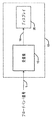
図3を参照すると、本発明の原理に係るデバイス10の例示的実施形態が示されている。デバイス10は、あらゆるプロセッサベースのプラットフォームをも代表するものであり、例えば、PC、サーバ、セットトップボックス、携帯情報端末(PDA)、携帯電話、モバイルディジタルテレビジョン(DTV)、DTV等である。この点に関して、デバイス10は、(図示されていない)関連メモリを有する1つ以上のプロセッサを含み、受信機15をも含む。後者は、(図示されていない)アンテナを介してブロードキャスト信号1を受信し、アプリケーションに対する出力信号16を出力装置20に出力する。出力装置20は、破線の形態で表されるようなデバイス10の一部であってもよいし又はその一部でなくてもよい。この例の内容において、出力装置20は、ユーザが選択されたテレビ番組を見ることが可能なディスプレイである。この例について説明するために、ブロードキャスト信号1は、DVB−T/Hサービス、すなわち、DTVトランスポートストリームを代表するものであり、DTVトランスポートストリームは少なくとも1つのテレビチャンネルに対してビデオ、オーディオ、及び/又は、システム情報を含むことが想定されており、ブロードキャスト信号1は直交周波数分割多重(OFDM)方式等のマルチ搬送波変調方式を使用してこの情報を伝達することが想定されている。しかしながら、本発明の概念は、周波数の補完を実行する受信機に限定されないし、いかなる受信機にも適用することができる。発明の原理によれば、受信機15は受信信号の多経路遅延(Tmax)を決定し、周波数補間器のバンド幅を決定された多経路遅延の関数として調整し、周波数補間器は受信信号の副搬送波のチャンネル状態情報を補間する。
Referring to FIG. 3, an exemplary embodiment of a
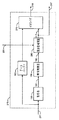
ここで、図4を参照すると、受信機15の例示的部分が示されている。本発明の概念に関連する受信機15のその部分のみが示されている。本発明の概念を除き、図4に示した要素は知られており、本明細書において説明しない。この例においては、受信機は2Kモードで動作していると仮定されている。尚、8Kモードにおける動作は同様であるので、本明細書には説明していない。受信機15は、ダウンコンバータ200、高速フーリエ変換(FFT)要素205、搬送波位相誤差(CPE)除去要素210、適応型チャネル推定・イコライザ(CHE)220、デマッパ220、及びコントローラ230を含む。さらに、受信機15はプロセッサベースのシステムであり、図4の破線のボックスの形態で示されたプロセッサ290とメモリ295によって表されているように1つ以上のプロセッサと、関連メモリとを含む。例えば、コントローラ230はマイクロプロセッサとして実装され得る。これに関連して、コンピュータプログラム又はソフトウェアは、プロセッサ290が実行できるようメモリ295に記憶される。後者は、1つ以上の内蔵プログラム制御プロセッサを代表するものであり、これらは受信機の機能に専用されるべきではない。例えば、プロセッサ290は受信機15の他の機能をも制御し得る。例えば、受信器15が、より大規模なデバイスの一部である場合、プロセッサ290はこのデバイスの他の機能を制御し得る。メモリ295は、いかなる記憶装置をも代表するものであり、例えば、ランダムアクセスメモリ(RAM)、リードオンリーメモリ(ROM)等は、受信機15の内部及び/又は外部にあってもよく、必要に応じて、揮発性及び/又は不揮発性である。
Referring now to FIG. 4, an exemplary portion of the
FFT要素205は受信されたベースバンド信号204を処理する。後者はダウンコンバータ200によって出力される。そのダウンコンバータ200は、選択されたRFチャネルに波長を合わされた受信機15のチューナ(図示せず)の一部である。その選択されたRFチャネルは図3のブロードキャスト信号1に関連付けられている。FFT要素205は受信されたベースバンド信号204を時間領域から周波数領域に変換し、FFT出力信号206を出力する。尚、FFT出力信号206は同相且つ直交成分を有する複素信号に相当する。通常、FFT要素105は、当技術分野で知られているようにバタフライ演算を実行し、並び換えられた出力データ(2k作動モードにおける2048複素サンプル)を出力する。そういうものとして、FFT要素205は、スペクトルのシフトを実行して、FFT出力データを再編成し又はシフトせしめて、上述のDVB−T規格に従って副搬送波のロケーションを満たす。CPE除去要素210はFFT出力信号206を処理して、搬送波の位相誤差の全てをも取り除き、CPE補正信号211をCHE要素215に出力する。(さらに、以下に説明する)発明の原理によれば、CHE要素215はCPE補正信号211を処理する。これは、(a)CSI信号217を出力するためにチャンネル状態情報(CSI)を決定し、且つ(b)受信されたベースバンドの信号を均等化して、均等化された信号216を出力するために、あらゆる伝送チャネルのひずみを補完するためである。当技術分野で知られているように、CSI信号217は、復号化の際に使用するためのビットメトリックスを取得するのに使用され得る(図4に示されていない)。均等化された信号216はデマッパ220に利用される。後者のプロセスは、ことによると送信されたシンボルに関して困難な決断を(すなわち、困難な復号化)するために信号216を均等化して、シンボルストリーム221を出力する。そのシンボルストリーム221は、受信機(例えば、図示しないソフトの複合化)によってさらに処理されて、例えば、そこに伝送されたコンテンツ(音声、映像等)を復元する。最終的に、コントローラ230はFFT出力信号206を処理して、関連付けたれた多経路遅延Tmaxを決定する。この例において、コントローラ230は、多経路遅延Tmaxを決定するためにFFT出力信号206を時間領域に変換し直す。本発明の概念を除き、時間領域での多経路遅延の計算は、知られており、本明細書において説明しない。例えば、コントローラ230は、多経路遅延Tmaxを代表するものとして、受信信号におけるエコーの長さを決定する。一度、多経路遅延Tmaxが決定されると、及び、発明の原理によれば、コントローラ230は信号231を介して適応型CHE215の周波数補間器のバンド幅を変更する。以下でさらに説明する本発明の特徴によれば、コントローラ230は、また、デマッパ220で使用する分割因子を信号232を介して変化せしめ得る。
The
次に、図5に目に向けると、本発明の原理に係る適応型CHE215の例示的実施形態が示されている。本発明の概念を除き、図5に示す要素は、知られており、本明細書において説明しない。CHE要素215は、前処理要素150、時間補間器155、周波数補間器260、データバッファ165、およびイコライザ270を含む。データバッファ165は、イコライザ270による処理前に、CPE補正信号211を単に遅延せしめる。一方、CSI情報は低処理パスにおける要素(前処理要素150、時間補間器155、及び周波数補間器260)によって決定される。上述したように、イコライザ270は受信されたベースバンド信号(例えば、CPE補正信号211の遅延されたもの)を均等化して、伝送チャネルのひずみを補完し、均等化された信号216を出力する。
Turning now to FIG. 5, an exemplary embodiment of an
低処理パスに関して、及び、本発明の概念を除き、チャネル推定処理は、先に説明したようにDVB−Tに含まれるパイロット信号を利用している。特に、前処理要素150は、CPE補正信号211を処理して、受信されたSPsのCSIを決定する。パイロットは既知の値と共に伝送されるので、前処理要素150はそれら知られた値に対して受信されたSPsを処理して、それらチャンネル状態情報を決定する。それらチャンネル状態情報は、前処理出力信号151を介して出力される。そして、SPs(151)のCSIは時間補間器155によって処理される。特に、時間補間器155は、3つの副搬送波毎のCSIを(時間領域で)補間し、(SPsのCSIと、3つの副搬送波毎の時間で補間された新たなCSIを含む)出力信号156を出力する。最終的に、周波数補間器260は出力信号156を処理する。特に、周波数補間器260は、全ての副搬送波のCSIを(周波数領域で)補間し(実際には、例えばSPsの先に決定されたCSIをスムージングする)、(すべての副搬送波に対するCSIのすべてを与える)CSI信号217を出力する。イコライザ270はCSI信号217を利用して、受信されたベースバンド信号に関する上述の均等化処理を実行し、上述したように、CSI信号217は、復号化に使用するビットメトリックスを取得するのに使用され得る。
As for the low processing path and excluding the concept of the present invention, the channel estimation process uses a pilot signal included in DVB-T as described above. In particular, the
発明の原理によれば、CHE215は異なる多経路遅延に適合される。実例として、周波数補間器260のバンド幅は多経路遅延の関数として変化する。例えば、周波数補間器260は、入力信号をフィルタにかけるための多数のフィルタ係数(図示せず)を含む。これらフィルタ係数の値又は範囲は、周波数補間器260の所定のバンド幅の関数として(信号231を介して)コントローラ230によって設定される。特に、Tmaxの値が小さいとき、バンド幅は、有効な雑音フィルタリングを確実にするために小さいはずである。したがって、(周波数補間器260の)フィルタに関するインパルス応答の主ローブは低く、フィルタ係数の範囲は小さい。しかしながら、Tmaxの値が大きいとき、バンド幅は、大きい値に設定されるべきである。したがって、(周波数補間器260の)フィルタに関するインパルス応答の主ローブは高く、フィルタ係数の範囲は広い。実例として、コントローラ230は、(例えば、コントローラ230のメモリに記憶された)多数の記憶された係数群から一群のフィルタ係数値を選択し、各係数群は周波数補間器260の特定のバンド幅設定に関連づけられている。この例においては、コントローラ230は、単に2つの係数群を有する。すなわち、周波数補間器260のバンド幅を増大せしめる係数群と周波数補間器260のバンド幅を低減せしめる係数群である。
In accordance with the principles of the invention,
本発明の特徴によれば、尚、係数群の範囲は異なるので、受信機のリソースはより効率的に管理され得る。例えば、係数群の範囲がより大きい場合、より長いワード長が、例えば、固定長処理のフィルタ係数に使用されなければならない。しかしながら、係数群の範囲がより小さい場合、より短いワード長が、例えば、同一の精度を得るための固定長処理のフィルタ係数に使用され得る。より短いワード長を使用することができることにより、受信機において必要とされるリソースがより少なくなる。実例として、コントローラ230は、関連づけられたパラメータを管理することによって固定長レコード処理に使用されるワード長を調整でし得る。関連づけられたパラメータは、ワード長を固定長プロセッサ(例えば、受信機15のデジタル信号プロセッサ)において設定する。
According to the characteristics of the present invention, the range of the coefficient group is different, so that the resources of the receiver can be managed more efficiently. For example, if the range of coefficients is larger, a longer word length must be used, for example, for fixed length processing filter coefficients. However, if the coefficient group range is smaller, a shorter word length can be used, for example, for fixed length processing filter coefficients to obtain the same accuracy. The ability to use shorter word lengths requires less resources at the receiver. Illustratively, the
しかしながら、固定長処理は、本発明の他の特徴に係るコントローラ215によって動的に調整され得るものの、異なるアプローチがワード長を設定するのに使用され得る。特に、コントローラ230は、固定長処理の全てに用いるために、ワード長をより低い値又は最低値に調整し得る。その結果、受信機のリソースは、周波数補間器260のそれらバンド幅の設定に対する低減された精度において、より大なるワード長を必要とするものの、より効率的に管理される。
However, although fixed length processing can be dynamically adjusted by the
ここで、図6及び図7を参照すると、本発明の原理に係るチャンネル状態情報を決定する受信機に用いる例示的フロー図が示されている。ステップ405において、受信機は、受信されたブロードキャスト信号(例えば、図3の受信機15)をダウンコンバートする。ステップ410において、受信機は、受信された信号(例えば、図4のコントローラ230)に関連付けられた多経路遅延Tmaxを決定する。最終的に及び発明の原理によれば、受信機は、ステップ415において、周波数補間器のバンド幅を決定された多経路遅延の関数として調整する。
6 and 7, there is shown an exemplary flow diagram for use in a receiver that determines channel state information according to the principles of the present invention. In
図6のステップ415の一例が図7のフローチャートに示されている。様々な値の又は範囲のTmaxに相当する多数のフィルタ係数群が、図4のコントローラ230に記憶されることが想定されている。例えば、コントローラ230が2つの係数群、Cl及びC2を記憶することを想定すると、C1群は、低減されたバンド幅と、より短いワード長とに関連づけられ、一方、C2群は、増大されたバンド幅と、より長いワード長とに関連づけられる。実例として、周波数補間器260は12のタップを含む、すなわち、係数群の各々は、例えば、12のフィルタ係数に対して値を含むことが想定されている。その12のフィルタ係数は、
An example of
![]()
![]()
及び as well as
![]()
![]()
である。ここで、上付きは、個別のフィルタ係数の各々に対する特定の係数群を示しており、下付は係数群のフィルタ係数の特定値を示している。したがって、異なる固定点処理が、フィルタ係数の異なるサイズのワード長に対して使用され得る。例えば、より短いワード長に対しては、周波数領域におけるデータは、12ビット(バイナリー・ディジット)によって表される。この例において、C1群の係数の各々は12ビットのワード長を有する。しかしながら、より大なるワード長に対して、周波数領域のデータは、例えば、14ビットによって表される。この例において、係数群C2の係数の各々は14ビットのワード長を有する。その結果、多経路遅延が低いとき、より小さいサイズのフィルタ係数を処理することは、より大なるサイズのフィルタ係数を処理することと同程度効果的である。しかしながら、より小さいサイズのフィルタ係数を処理することによって、受信機はより効率的に動作する。 It is. Here, the superscript indicates a specific coefficient group for each individual filter coefficient, and the subscript indicates the specific value of the filter coefficient of the coefficient group. Thus, different fixed point processing can be used for different sized word lengths of filter coefficients. For example, for shorter word lengths, data in the frequency domain is represented by 12 bits (binary digits). In this example, each of the group C1 coefficients has a word length of 12 bits. However, for larger word lengths, the frequency domain data is represented, for example, by 14 bits. In this example, each coefficient of the coefficient group C2 has a word length of 14 bits. As a result, when the multipath delay is low, processing smaller size filter coefficients is as effective as processing larger size filter coefficients. However, by processing smaller size filter coefficients, the receiver operates more efficiently.
図7のフロー図を継続すると、ステップ450において、受信機は、決定された多経路遅延Tmaxを、所定値TMP(例えば、100μ秒(マイクロ秒)の値)と比較する。TMPの値は実験的に決定され得る。Tmaxの値がTMPの値よりも大である場合、受信機は、係数群C2を選択することによって、ステップ475においてCHE215の周波数補間器260のバンド幅を増大させる。ステップ480において、受信機は、ワードサイズを大きく設定して、係数群C2を周波数補間器260にロードする。そして、ステップ485において、受信機は、デマッパ220に使用するために除算因子を1に設定する(図4の信号232)。他方、Tmaxの値がTMPの値よりも大でない場合、受信機は、係数群C1を選択することによって、ステップ455において、CHE215の周波数補間器260のバンド幅を低減させ、ワードサイズを短く設定し、ステップ465においてデマッパ220に使用するためにステップ460において係数郡C1を周波数補間器260にロードし、除算因子を1/4に設定する(図4に関する信号232)。尚、除算因子はワード長の差異yに関連する。除算因子は1/2yである。例えば、本明細書において、ワード長の差は2ビットであり、低設定に対する除算因子は1/22=1/4である。
Continuing with the flow diagram of FIG. 7, in
上述したように、発明の原理によれば、受信機は、チャンネル状態情報を決定するために、周波数補間器のバンド幅を多経路遅延の関数として変更する。有利にも、この手法は従来のチャンネル推定技術よりも少ないリソースをも必要とし得る。例えば、関連タップ係数のワードサイズを多経路遅延の関数として変化させることができる。尚、本発明の概念は2つの係数群との関連で記載されていたが、本発明の概念はそのように限定されず、2つより多い係数群が、異なる範囲のTmaxの値に使用され得るように、使用され得る。さらに、係数群は同一の又は異なるワード長を有し得る。さらに、尚、本発明の概念はDTV−Tブロードキャスト信号に照らして図示されたが、本発明の概念は、ソフトウェア定義の無線受信機、DMB−T/H受信機等のチャンネル状態情報を決定し得る他の態様の受信機に限定されず、且つこれらに適用することができる。 As described above, according to the principles of the invention, the receiver changes the bandwidth of the frequency interpolator as a function of multipath delay in order to determine channel state information. Advantageously, this approach may require less resources than conventional channel estimation techniques. For example, the word size of the associated tap coefficient can be changed as a function of multipath delay. The concept of the present invention has been described in the context of two coefficient groups, but the concept of the present invention is not so limited, and more than two coefficient groups are used for different ranges of T max values. As can be used. Furthermore, the coefficient groups can have the same or different word lengths. Furthermore, although the concept of the present invention is illustrated in the context of a DTV-T broadcast signal, the concept of the present invention determines channel state information for software-defined radio receivers, DMB-T / H receivers, etc. It is not limited to the receiver of the other aspect to obtain, It can apply to these.
先に示したように、上記は本発明の原理について例示しているにすぎず、当業者であれば、本明細書に明示的に説明しないものの本発明の原理を具現化し且つその趣旨と範囲内にある多数の代替装置を考え出すことができるであろうことも十分理解されるだろう。例えば、個別の機能的要素に照らして例示されているものの、これら機能的要素は、1つ以上の集積回路(IC)において具現化され得る。同様に、別々の要素として示されているものの、いずれかの要素又はすべての要素は、例えば、図6−7等に示された1つ以上のステップに対応する関連ソフトウェアを例えば実行する記憶されたプログラム制御のプロセッサ、例えば、デジタル信号プロセッサにおいて実装され得る。さらに、本発明の原理は、例えば、衛星放送、ワイヤレス−フィデリティー(Wi−Fi)、セルラー等の他の態様の通信システムに利用することができる。実際に、本発明の概念は、固定型受信機又は携帯型受信機にも利用することができる。したがって、多数の変更が例示的実施形態になされ得ること及び添付した特許請求の範囲に記載された本発明の趣旨及び範囲から逸脱せずに、他の装置が考えられ得ることが理解されるべきである。 As indicated above, the above is merely illustrative of the principles of the present invention, and those skilled in the art will embody the principles of the present invention and express their spirit and scope, although not explicitly described herein. It will also be appreciated that many alternative devices could be devised. For example, although illustrated in the context of individual functional elements, these functional elements may be embodied in one or more integrated circuits (ICs). Similarly, although shown as separate elements, any or all of the elements are stored, for example, executing associated software corresponding to one or more of the steps shown in FIGS. 6-7, for example. It may be implemented in a program-controlled processor such as a digital signal processor. Furthermore, the principle of the present invention can be used for communication systems of other modes such as satellite broadcasting, wireless fidelity (Wi-Fi), cellular, and the like. Indeed, the concept of the present invention can also be applied to fixed or portable receivers. Accordingly, it should be understood that numerous modifications can be made to the exemplary embodiments and that other devices can be envisaged without departing from the spirit and scope of the invention as set forth in the appended claims. It is.
Claims (6)
受信信号の多経路遅延を決定するステップと、
周波数補間器のバンド幅を前記決定された多経路遅延の関数として調整するステップと、を含み、
前記周波数補間器は前記受信信号の副搬送波に関するチャンネル状態情報を補間し、
前記調整するステップはさらに、
前記周波数補間器のフィルタ係数値を前記決定された多経路遅延の関数として設定するステップを含み、
前記設定するステップはさらに、
前記フィルタ係数値の少なくともいくつかのワード長を前記決定された多経路遅延の関数として変更するステップ、
を含む、前記方法。 A O FD M method used in receiver apparatus,
Determining the multipath delay of the received signal;
It includes a step of adjusting the bandwidth of the frequency interpolator as a function of the multi-path delay which is the determined, and
The frequency interpolator interpolates channel state information related to subcarriers of the received signal,
The adjusting step further comprises:
Setting a filter coefficient value of the frequency interpolator as a function of the determined multipath delay;
The setting step further includes:
Changing at least some word lengths of the filter coefficient values as a function of the determined multipath delay ;
Said method.
前記デマッパは、前記受信信号から復元された受信シンボルストリームを提供する、請求項1に記載の方法。 Further comprising the step of setting a dividing factor of the demapper as a function of the multi-path delay which is the determined,
The demapper provides a received symbol stream recovered from the received signal, The method of claim 1.
前記受信信号を提供するために、前記ダウンコンバートされた信号に対して高速フーリエ変換(FFT)を実行するステップと、
をさらに含む、請求項1に記載の方法。 Downconverting the received radio frequency signal to provide a downconverted signal;
Performing a fast Fourier transform (FFT) on the downconverted signal to provide the received signal ;
The method of claim 1, further comprising:
受信信号の副搬送波に関するチャンネル状態情報を提供する周波数補間器と、
前記受信信号の多経路遅延を決定し、前記周波数補間器のバンド幅を前記決定された多経路遅延の関数として調整するプロセッサと、
を含み、前記プロセッサは、前記周波数補間器のフィルタ係数値を前記決定された多経路遅延の関数として設定し、
前記プロセッサは、前記フィルタ係数値の少なくともいくつかのワード長を前記決定された多経路遅延の関数として変更する、前記OFDM受信機。 An OFDM receiver,
A frequency interpolator for providing channel state information on the subcarriers of the received signal,
A processor wherein determining the multi-path delay of the received signal and adjusts the bandwidth of the frequency interpolator as a function of the multi-path delay which is the determined,
Wherein the said processor sets filter coefficient values of the frequency interpolator as a function of the multi-path delay which is the determined,
The OFDM receiver , wherein the processor changes at least some word lengths of the filter coefficient values as a function of the determined multipath delay.
前記プロセッサは、前記デマッパの分割因子を前記決定された多経路遅延の関数として設定する、請求項4に記載のOFDM受信機。 Further comprising a demapper for providing a received symbol stream recovered from the received signal,
Wherein the processor sets a dividing factor of the demapper as a function of the multi-path delay which is the determined, OFDM receiver of claim 4.
前記ダウンコンバートされた信号を処理して前記受信信号を提供するための高速フーリエ変換(FFT)要素と、
をさらに含む、請求項4に記載のOFDM受信機。 A downconverter that downconverts the received radio frequency signal to provide a downconverted signal;
A Fast Fourier Transform (FFT) element for processing the downconverted signal to provide the received signal ;
The OFDM receiver according to claim 4 , further comprising:
Applications Claiming Priority (3)
| Application Number | Priority Date | Filing Date | Title |
|---|---|---|---|
| EP07301390A EP2043314A1 (en) | 2007-09-25 | 2007-09-25 | A self-adaptive frequency interpolator for use in a multi-carrier receiver |
| EP07301390.6 | 2007-09-25 | ||
| PCT/IB2008/002448 WO2009040623A2 (en) | 2007-09-25 | 2008-09-19 | A self-adaptive frequency interpolar for use in a multi-carrier receiver |
Publications (3)
| Publication Number | Publication Date |
|---|---|
| JP2010541362A JP2010541362A (en) | 2010-12-24 |
| JP2010541362A5 JP2010541362A5 (en) | 2011-11-10 |
| JP5337804B2 true JP5337804B2 (en) | 2013-11-06 |
Family
ID=39032423
Family Applications (1)
| Application Number | Title | Priority Date | Filing Date |
|---|---|---|---|
| JP2010526386A Expired - Fee Related JP5337804B2 (en) | 2007-09-25 | 2008-09-19 | Self-adaptive frequency interpolator for use with multi-carrier receivers. |
Country Status (7)
| Country | Link |
|---|---|
| US (1) | US8699588B2 (en) |
| EP (2) | EP2043314A1 (en) |
| JP (1) | JP5337804B2 (en) |
| KR (1) | KR101394833B1 (en) |
| CN (1) | CN101904142B (en) |
| BR (1) | BRPI0816279A2 (en) |
| WO (1) | WO2009040623A2 (en) |
Cited By (2)
| Publication number | Priority date | Publication date | Assignee | Title |
|---|---|---|---|---|
| US9724801B2 (en) | 2013-06-28 | 2017-08-08 | Fanuc Corporation | Deburring device including visual sensor and force sensor |
| JP7096146B2 (en) | 2018-12-21 | 2022-07-05 | 日立グローバルライフソリューションズ株式会社 | Deburring device for stator and deburring control method for stator |
Families Citing this family (5)
| Publication number | Priority date | Publication date | Assignee | Title |
|---|---|---|---|---|
| US8374285B2 (en) * | 2008-05-05 | 2013-02-12 | Texas Instruments Incorporated | System and method for time domain interpolation of signals for channel estimation |
| KR101511901B1 (en) * | 2014-01-29 | 2015-04-13 | 연세대학교 산학협력단 | Method and Device for Demapping Symbol |
| CN104394111A (en) * | 2014-08-13 | 2015-03-04 | 深圳市国创新能源研究院 | Adaptive modulation method and device for LTE downlink |
| EP3767990A4 (en) * | 2018-03-14 | 2021-10-27 | Ntt Docomo, Inc. | User equipment and wireless communication method |
| CN112019284B (en) * | 2020-08-27 | 2022-06-17 | 中电科思仪科技股份有限公司 | Narrow-band signal time difference calculation method and system under low signal-to-noise ratio |
Family Cites Families (22)
| Publication number | Priority date | Publication date | Assignee | Title |
|---|---|---|---|---|
| JP2772286B2 (en) * | 1996-08-30 | 1998-07-02 | 株式会社次世代デジタルテレビジョン放送システム研究所 | Orthogonal frequency division multiplex signal demodulator |
| JPH10257013A (en) | 1997-03-14 | 1998-09-25 | Toshiba Corp | Receiver |
| GB2325125B (en) * | 1997-05-02 | 2002-06-05 | Lsi Logic Corp | Demodulating digital video broadcast signals |
| GB2355164B (en) * | 1999-10-07 | 2004-06-09 | Oak Technology Inc | Demodulator circuit |
| JP3606448B2 (en) | 2000-08-21 | 2005-01-05 | 株式会社ケンウッド | Orthogonal frequency division multiplex signal receiving apparatus and orthogonal frequency division multiplex signal receiving method |
| WO2002017529A1 (en) | 2000-08-21 | 2002-02-28 | Kabushiki Kaisha Kenwood | Orthogonal frequency division multiplexed signal receiving apparatus and orthogonal frequency division multiplexed signal receiving method |
| GB2370952B (en) * | 2001-01-05 | 2003-04-09 | British Broadcasting Corp | Improvements in channel state measurement and in discriminating digital values from a received signal suitable for use with OFDM signals |
| JP3979789B2 (en) | 2001-01-15 | 2007-09-19 | 三洋電機株式会社 | Digital signal receiver |
| JP2002290209A (en) | 2001-03-28 | 2002-10-04 | Nippon Precision Circuits Inc | Decimation filter |
| GB2388756A (en) * | 2002-05-17 | 2003-11-19 | Hewlett Packard Co | Calculating an estimate of bit reliability in a OFDM receiver by multiplication of the channel state modulus |
| US20040218519A1 (en) | 2003-05-01 | 2004-11-04 | Rong-Liang Chiou | Apparatus and method for estimation of channel state information in OFDM receivers |
| JP2005260331A (en) * | 2004-03-09 | 2005-09-22 | Hitachi Kokusai Electric Inc | Ofdm receiver |
| CN1977505A (en) * | 2004-05-12 | 2007-06-06 | 汤姆森许可公司 | Constellation location dependent step sizes for equalizer error signals |
| KR100585155B1 (en) * | 2004-08-19 | 2006-05-30 | 삼성전자주식회사 | A Method of frequency domain channel estimation using a transform domain complex filter for a DVB-T Receiver |
| KR100604926B1 (en) * | 2005-01-07 | 2006-07-28 | 삼성전자주식회사 | Digital Video Broadcasting Terrestrial receiver and method for selecting the channel and Fast Fourier Transform window using the same |
| JP4703253B2 (en) | 2005-05-06 | 2011-06-15 | パナソニック株式会社 | Communication terminal device |
| US7561633B2 (en) * | 2005-07-13 | 2009-07-14 | Leanics Corporation | System and method for MIMO equalization for DSP transceivers |
| JP4611385B2 (en) | 2005-08-23 | 2011-01-12 | 三菱電機株式会社 | Wireless communication system and communication apparatus |
| DE602005013683D1 (en) * | 2005-12-14 | 2009-05-14 | Ericsson Telefon Ab L M | Method and device for signal processing |
| JP2007202081A (en) | 2006-01-30 | 2007-08-09 | Sony Corp | Ofdm demodulator and ofdm demodulation method |
| JP4664234B2 (en) * | 2006-05-24 | 2011-04-06 | 富士通セミコンダクター株式会社 | OFDM receiver |
| US7864885B2 (en) * | 2006-11-15 | 2011-01-04 | Samsung Electronics Co., Ltd. | Multiple input multiple output (MIMO) transceiver with pooled adaptive digital filtering |
-
2007
- 2007-09-25 EP EP07301390A patent/EP2043314A1/en not_active Withdrawn
-
2008
- 2008-09-19 CN CN200880108421.9A patent/CN101904142B/en not_active Expired - Fee Related
- 2008-09-19 BR BRPI0816279A patent/BRPI0816279A2/en not_active Application Discontinuation
- 2008-09-19 KR KR1020107006447A patent/KR101394833B1/en not_active IP Right Cessation
- 2008-09-19 EP EP08834622.6A patent/EP2193639B1/en not_active Not-in-force
- 2008-09-19 JP JP2010526386A patent/JP5337804B2/en not_active Expired - Fee Related
- 2008-09-19 US US12/733,455 patent/US8699588B2/en not_active Expired - Fee Related
- 2008-09-19 WO PCT/IB2008/002448 patent/WO2009040623A2/en active Application Filing
Cited By (2)
| Publication number | Priority date | Publication date | Assignee | Title |
|---|---|---|---|---|
| US9724801B2 (en) | 2013-06-28 | 2017-08-08 | Fanuc Corporation | Deburring device including visual sensor and force sensor |
| JP7096146B2 (en) | 2018-12-21 | 2022-07-05 | 日立グローバルライフソリューションズ株式会社 | Deburring device for stator and deburring control method for stator |
Also Published As
| Publication number | Publication date |
|---|---|
| EP2193639A2 (en) | 2010-06-09 |
| KR20100058595A (en) | 2010-06-03 |
| BRPI0816279A2 (en) | 2019-09-10 |
| CN101904142A (en) | 2010-12-01 |
| US20110129035A1 (en) | 2011-06-02 |
| US8699588B2 (en) | 2014-04-15 |
| WO2009040623A3 (en) | 2009-05-22 |
| JP2010541362A (en) | 2010-12-24 |
| WO2009040623A2 (en) | 2009-04-02 |
| CN101904142B (en) | 2014-05-07 |
| KR101394833B1 (en) | 2014-05-27 |
| EP2043314A1 (en) | 2009-04-01 |
| EP2193639B1 (en) | 2015-03-04 |
Similar Documents
| Publication | Publication Date | Title |
|---|---|---|
| JP5337804B2 (en) | Self-adaptive frequency interpolator for use with multi-carrier receivers. | |
| US8681850B2 (en) | Signal processing apparatus, signal processing method and program | |
| US8937996B2 (en) | Receiver with ICI noise estimation | |
| EP1872551A1 (en) | Time domain windowing and inter-carrier interference cancellation | |
| WO1999043114A1 (en) | Method and apparatus for signal reception, and medium | |
| KR101395686B1 (en) | Apparatus and method for removing common phase error in a dvb-t/h receiver | |
| EP3289744A2 (en) | Selecting angular active constellation extension for non-square constellations and extension along x or y axis for square constellations | |
| EP2157753B1 (en) | Control of interpolation for channel estimation | |
| KR101406160B1 (en) | Apparatus and method for removing common phase error in a dvb-t/h receiver | |
| EP2051467A1 (en) | Apparatus and method for channel estimation | |
| JP2005191662A (en) | Method of demodulating ofdm signal |
Legal Events
| Date | Code | Title | Description |
|---|---|---|---|
| A521 | Request for written amendment filed |
Free format text: JAPANESE INTERMEDIATE CODE: A523 Effective date: 20110920 |
|
| A621 | Written request for application examination |
Free format text: JAPANESE INTERMEDIATE CODE: A621 Effective date: 20110920 |
|
| A977 | Report on retrieval |
Free format text: JAPANESE INTERMEDIATE CODE: A971007 Effective date: 20130312 |
|
| A131 | Notification of reasons for refusal |
Free format text: JAPANESE INTERMEDIATE CODE: A131 Effective date: 20130322 |
|
| A521 | Request for written amendment filed |
Free format text: JAPANESE INTERMEDIATE CODE: A523 Effective date: 20130624 |
|
| TRDD | Decision of grant or rejection written | ||
| A01 | Written decision to grant a patent or to grant a registration (utility model) |
Free format text: JAPANESE INTERMEDIATE CODE: A01 Effective date: 20130705 |
|
| A61 | First payment of annual fees (during grant procedure) |
Free format text: JAPANESE INTERMEDIATE CODE: A61 Effective date: 20130805 |
|
| R150 | Certificate of patent or registration of utility model |
Ref document number: 5337804 Country of ref document: JP Free format text: JAPANESE INTERMEDIATE CODE: R150 Free format text: JAPANESE INTERMEDIATE CODE: R150 |
|
| R250 | Receipt of annual fees |
Free format text: JAPANESE INTERMEDIATE CODE: R250 |
|
| LAPS | Cancellation because of no payment of annual fees |