JP4611385B2 - Wireless communication system and communication apparatus - Google Patents
Wireless communication system and communication apparatus Download PDFInfo
- Publication number
- JP4611385B2 JP4611385B2 JP2007531974A JP2007531974A JP4611385B2 JP 4611385 B2 JP4611385 B2 JP 4611385B2 JP 2007531974 A JP2007531974 A JP 2007531974A JP 2007531974 A JP2007531974 A JP 2007531974A JP 4611385 B2 JP4611385 B2 JP 4611385B2
- Authority
- JP
- Japan
- Prior art keywords
- delay time
- signal
- multipath delay
- guard
- guard interval
- Prior art date
- Legal status (The legal status is an assumption and is not a legal conclusion. Google has not performed a legal analysis and makes no representation as to the accuracy of the status listed.)
- Active
Links
Images


Classifications
-
- H—ELECTRICITY
- H04—ELECTRIC COMMUNICATION TECHNIQUE
- H04B—TRANSMISSION
- H04B1/00—Details of transmission systems, not covered by a single one of groups H04B3/00 - H04B13/00; Details of transmission systems not characterised by the medium used for transmission
- H04B1/69—Spread spectrum techniques
- H04B1/713—Spread spectrum techniques using frequency hopping
- H04B1/715—Interference-related aspects
-
- H—ELECTRICITY
- H04—ELECTRIC COMMUNICATION TECHNIQUE
- H04L—TRANSMISSION OF DIGITAL INFORMATION, e.g. TELEGRAPHIC COMMUNICATION
- H04L27/00—Modulated-carrier systems
- H04L27/26—Systems using multi-frequency codes
-
- H—ELECTRICITY
- H04—ELECTRIC COMMUNICATION TECHNIQUE
- H04J—MULTIPLEX COMMUNICATION
- H04J9/00—Multiplex systems in which each channel is represented by a different type of modulation of the carrier
-
- H—ELECTRICITY
- H04—ELECTRIC COMMUNICATION TECHNIQUE
- H04L—TRANSMISSION OF DIGITAL INFORMATION, e.g. TELEGRAPHIC COMMUNICATION
- H04L25/00—Baseband systems
- H04L25/02—Details ; arrangements for supplying electrical power along data transmission lines
- H04L25/03—Shaping networks in transmitter or receiver, e.g. adaptive shaping networks
- H04L25/03006—Arrangements for removing intersymbol interference
- H04L25/03159—Arrangements for removing intersymbol interference operating in the frequency domain
-
- H—ELECTRICITY
- H04—ELECTRIC COMMUNICATION TECHNIQUE
- H04L—TRANSMISSION OF DIGITAL INFORMATION, e.g. TELEGRAPHIC COMMUNICATION
- H04L27/00—Modulated-carrier systems
- H04L27/26—Systems using multi-frequency codes
- H04L27/2601—Multicarrier modulation systems
- H04L27/2602—Signal structure
- H04L27/26025—Numerology, i.e. varying one or more of symbol duration, subcarrier spacing, Fourier transform size, sampling rate or down-clocking
-
- H—ELECTRICITY
- H04—ELECTRIC COMMUNICATION TECHNIQUE
- H04L—TRANSMISSION OF DIGITAL INFORMATION, e.g. TELEGRAPHIC COMMUNICATION
- H04L5/00—Arrangements affording multiple use of the transmission path
- H04L5/003—Arrangements for allocating sub-channels of the transmission path
- H04L5/0048—Allocation of pilot signals, i.e. of signals known to the receiver
-
- H—ELECTRICITY
- H04—ELECTRIC COMMUNICATION TECHNIQUE
- H04L—TRANSMISSION OF DIGITAL INFORMATION, e.g. TELEGRAPHIC COMMUNICATION
- H04L25/00—Baseband systems
- H04L25/02—Details ; arrangements for supplying electrical power along data transmission lines
- H04L25/03—Shaping networks in transmitter or receiver, e.g. adaptive shaping networks
- H04L25/03006—Arrangements for removing intersymbol interference
- H04L2025/0335—Arrangements for removing intersymbol interference characterised by the type of transmission
- H04L2025/03375—Passband transmission
- H04L2025/03414—Multicarrier
-
- H—ELECTRICITY
- H04—ELECTRIC COMMUNICATION TECHNIQUE
- H04L—TRANSMISSION OF DIGITAL INFORMATION, e.g. TELEGRAPHIC COMMUNICATION
- H04L27/00—Modulated-carrier systems
- H04L27/26—Systems using multi-frequency codes
- H04L27/2601—Multicarrier modulation systems
- H04L27/2602—Signal structure
- H04L27/2605—Symbol extensions, e.g. Zero Tail, Unique Word [UW]
-
- H—ELECTRICITY
- H04—ELECTRIC COMMUNICATION TECHNIQUE
- H04L—TRANSMISSION OF DIGITAL INFORMATION, e.g. TELEGRAPHIC COMMUNICATION
- H04L5/00—Arrangements affording multiple use of the transmission path
- H04L5/0001—Arrangements for dividing the transmission path
- H04L5/0003—Two-dimensional division
- H04L5/0005—Time-frequency
- H04L5/0007—Time-frequency the frequencies being orthogonal, e.g. OFDM(A), DMT
-
- H—ELECTRICITY
- H04—ELECTRIC COMMUNICATION TECHNIQUE
- H04L—TRANSMISSION OF DIGITAL INFORMATION, e.g. TELEGRAPHIC COMMUNICATION
- H04L5/00—Arrangements affording multiple use of the transmission path
- H04L5/0001—Arrangements for dividing the transmission path
- H04L5/0014—Three-dimensional division
- H04L5/0016—Time-frequency-code
- H04L5/0021—Time-frequency-code in which codes are applied as a frequency-domain sequences, e.g. MC-CDMA
-
- H—ELECTRICITY
- H04—ELECTRIC COMMUNICATION TECHNIQUE
- H04L—TRANSMISSION OF DIGITAL INFORMATION, e.g. TELEGRAPHIC COMMUNICATION
- H04L5/00—Arrangements affording multiple use of the transmission path
- H04L5/003—Arrangements for allocating sub-channels of the transmission path
- H04L5/0037—Inter-user or inter-terminal allocation
- H04L5/0039—Frequency-contiguous, i.e. with no allocation of frequencies for one user or terminal between the frequencies allocated to another
Landscapes
- Engineering & Computer Science (AREA)
- Signal Processing (AREA)
- Computer Networks & Wireless Communication (AREA)
- Physics & Mathematics (AREA)
- Mathematical Physics (AREA)
- Power Engineering (AREA)
- Mobile Radio Communication Systems (AREA)
- Noise Elimination (AREA)
Description
本発明は、マルチキャリア変復調方式を採用する無線通信システムに関するものであり、特に、マルチパス遅延時間が変化する通信環境で動作する通信装置に関するものである。 The present invention relates to a radio communication system that employs a multicarrier modulation / demodulation method, and more particularly to a communication apparatus that operates in a communication environment in which a multipath delay time changes.
従来から使用されている無線通信方式の一例として、OFDM(Orthogonal Frequency Division Multiplexing)方式およびDMT(Discrete Multi-tone)方式に代表されるマルチキャリア変復調方式がある。このマルチキャリア変復調方式は、たとえば、無線LAN,ADSL等に利用され、複数の周波数に直交したキャリアを配置し伝送する方式である。本方式では、送受信機間の伝搬路等により生じる遅延波(GB)の影響を除去するため、ガードインターバル(Guard Interval)もしくはサイクリックプレフィックス(Cyclic Prefix)を用いている。受信機では、たとえば、ガードインターバルを除いたOFDMシンボルに対してFFTを行うことによりガードインターバル内の遅延波の影響を除去し、データを復調している。 As an example of a wireless communication method that has been used conventionally, there is a multicarrier modulation / demodulation method represented by an OFDM (Orthogonal Frequency Division Multiplexing) method and a DMT (Discrete Multi-tone) method. This multi-carrier modulation / demodulation method is used for wireless LAN, ADSL, etc., for example, and is a method of arranging and transmitting carriers orthogonal to a plurality of frequencies. In this method, a guard interval (Guard Interval) or a cyclic prefix (Cyclic Prefix) is used in order to remove the influence of a delayed wave (GB) caused by a propagation path between the transceivers. In the receiver, for example, the influence of the delayed wave in the guard interval is removed by performing FFT on the OFDM symbol excluding the guard interval, and the data is demodulated.
一方で、上記OFDM方式は、ガードインターバルを超える遅延波が到来する状態においては符号間干渉が発生し、それに伴って、特性が大幅に劣化する。この問題は、送信機側で想定される遅延時間より長いガードインターバルを付加することにより解決できるが、この処理により、ガードインターバルのオーバヘッドが増加し、伝送効率が低下する。 On the other hand, in the OFDM scheme, intersymbol interference occurs in a state where a delayed wave exceeding the guard interval arrives, and the characteristics are greatly deteriorated accordingly. This problem can be solved by adding a guard interval longer than the delay time assumed on the transmitter side, but this processing increases the overhead of the guard interval and reduces the transmission efficiency.
また、セルラーシステムにおいては、たとえば、基地局と端末との距離が遠い場合、遅延時間が長くなり、基地局と端末との距離が近い場合は、遅延時間が短くなる。すなわち、セルラーシステムにおいては、端末の位置や環境により最適なガードインターバルの長さは異なる。 Further, in the cellular system, for example, when the distance between the base station and the terminal is long, the delay time becomes long, and when the distance between the base station and the terminal is short, the delay time becomes short. That is, in the cellular system, the optimum guard interval length varies depending on the terminal location and environment.
上記のような、ガードインターバルを超える遅延波が到来する場合、および端末の位置や環境により最適なガードインターバルの長さが異なる場合、に対応した従来技術としては、たとえば、下記特許文献1に記載の「OFDM通信システムおよびOFDM通信方法」がある。下記特許文献1では、従来固定長としていたガードインターバル長を、マルチパス遅延時間に応じて適応的に制御することにより、最大伝送効率を実現している。
As a conventional technique corresponding to the case where a delayed wave exceeding the guard interval arrives and the optimum length of the guard interval varies depending on the position and environment of the terminal, for example, described in
ここで、上記特許文献1の問題点について説明する。図9は、可変ガードインターバルを用いた場合の信号例を示す図であり、詳細には、マルチパス遅延時間が変化した場合の信号を示し、横軸は時間:tを表し、縦軸は、上図がマルチパス遅延時間(Normalized max delay time):Lcを表し、下図が周波数方向のサブキャリア(sub-carrier)を表している。図9により、マルチパス遅延時間が、時間変化とともに「中→小→大」と変化していることがわかる。また、信号は、データ情報を含むSymとガードインターバルGI(ガードインターバル長LGI)で構成され、「Lc≦LGI」であり、LcにあわせてLGIが変化していることがわかる。しかしながら、上記特許文献1に記載の従来技術では、適応制御によりOFDMシンボル長が変化するため、ハードウェア構成が複雑となる、という問題があった。Here, the problem of the
本発明は、上記に鑑みてなされたものであって、簡易なハードウェア構成でマルチパス遅延時間の変化に対応可能な通信装置を提供することを目的とする。 The present invention has been made in view of the above, and an object of the present invention is to provide a communication apparatus that can cope with a change in multipath delay time with a simple hardware configuration.
上述した課題を解決し、目的を達成するために、本発明にかかる無線通信システムは、マルチキャリア変復調方式を採用する無線通信システムであって、送信側の通信装置が、所定の推定処理により得られる伝搬路のマルチパス遅延時間に基づいて、データサブキャリアに対してマッピング処理を実行するマッピング手段(後述する実施の形態のData-Controlモジュール1およびDataモジュール2に相当)と、前記マルチパス遅延時間により得られるガードバンドに関する情報に応じて、データサブキャリア上の信号に付加するガードバンド量を変化させるガードバンド付加手段(GB-Controlモジュール3およびGB-Addモジュール4に相当)と、を備え、受信側の通信装置が、前記マルチパス遅延時間により得られるガードバンドに関する情報に基づいて、ガードインターバル(ガードインターバルを付加しない場合を含む)を超えるマルチパスを抑圧する等化手段(GB-Controlモジュール13およびGB-FEQモジュール14に相当)と、前記マルチパス遅延時間に基づいて、等化後の信号に対してデマッピング処理を実行するデマッピング手段(Data-Controlモジュール15およびDecモジュール16)と、を備えることを特徴とする。
In order to solve the above-described problems and achieve the object, a wireless communication system according to the present invention is a wireless communication system that employs a multi-carrier modulation / demodulation method, and a transmission-side communication device obtains by a predetermined estimation process. Mapping means (corresponding to Data-
本発明にかかる無線通信システムにおいては、伝搬路におけるマルチパス遅延時間に応じてガードバンド量を変化させることとしたので、シンボル長を変化させない簡易なハードウェア構成で、到来するマルチパスの遅延時間の変化に追従することができる、という効果を奏する。 In the wireless communication system according to the present invention, since the guard band amount is changed according to the multipath delay time in the propagation path, the delay time of the incoming multipath can be achieved with a simple hardware configuration that does not change the symbol length. There is an effect that it is possible to follow the change of.
1,1a,15,15a Data-Controlモジュール
2 Dataモジュール
3,3a,13,13a GB-Controlモジュール
4 GB-Addモジュール
5 IFFTモジュール
6 GB-Addモジュール
7a,17a MCS-Controlモジュール
8b,18b Rate-Controlモジュール
11 GI-Removalモジュール
12 FFTモジュール
14 GB-FEQモジュール
16 Decモジュール1, 1a, 15, 15a Data-
以下に、本発明にかかる無線通信システムおよび通信装置の実施の形態を図面に基づいて詳細に説明する。なお、この実施の形態によりこの発明が限定されるものではない。 Embodiments of a wireless communication system and a communication apparatus according to the present invention will be described below in detail with reference to the drawings. Note that the present invention is not limited to the embodiments.
実施の形態1.
図1は,本発明にかかる無線通信システムの構成例、すなわち、データ送信側の通信装置およびデータ受信側の通信装置の構成例を示す図であり、送信側の通信装置(変調器に相当)は、Data-Controlモジュール1と、Dataモジュール2と、GB-Controlモジュール3と、GB-Addモジュール4と、IFFTモジュール5と、GB-Addモジュール6と、を備え、受信側の通信装置(復調器に相当)は、GI-Removalモジュール11と、FFTモジュール12と、GB-Controlモジュール13と、GB-FEQモジュール14と、Data-Controlモジュール15と、Decモジュール16と、を備えている。
FIG. 1 is a diagram showing a configuration example of a wireless communication system according to the present invention, that is, a configuration example of a data transmission side communication device and a data reception side communication device, and a transmission side communication device (corresponding to a modulator). Includes a Data-
ここで、上記無線通信システムを構成する各モジュールの基本動作を簡単に説明する。Data-Controlモジュール1,15は、データサブキャリアの位置,量を指示する。Dataモジュール2は、送信データを符号化し、Data-Controlモジュール1の指示により周波数軸上のデータサブキャリアにマッピングする。GB-Controlモジュール3,13は、ガードバンド(GB:Guard Band)の種別,位置,量を指示する。GB-Addモジュール4は、GB-Controlモジュール3の指示によりDataモジュール1から出力されたデータサブキャリアにガードバンドを付加する。IFFTモジュール5は、周波数軸信号を時間軸信号へ変換する。GI-Addモジュール6は、時間軸信号にガードインターバルを付加する。GI-Removalモジュール11は、受信信号からガードインターバルを除去する。FFTモジュール12は、時間軸信号を周波数軸信号に変換する。GB-FEQモジュール14は、GB-Controlモジュール13の指示によりガードバンドを用いた周波数等化を行い、ガードインターバルを超える遅延波を抑圧する。Decモジュール16は、Data-Controlモジュール15の指示によりデータサブキャリアを復調(デマッピング処理)し、誤り訂正等の復号処理を行う。
Here, the basic operation of each module constituting the wireless communication system will be briefly described. The Data-
つづいて、本実施の形態の特徴的な動作について説明する。本実施の形態においては、Data-Controlモジュール1およびGB-Controlモジュール3が、伝搬路のマルチパス遅延時間に応じてデータサブキャリア,ガードバンドを制御する。具体的には、たとえば、TDD(Time Division Duplex)システムの場合には、自局受信信号から伝搬路のマルチパス遅延時間を推定し、FDD(Frequency Division Duplex)システムの場合には、相手局においてマルチパス遅延時間を推定し、フィードバックされたマルチパス遅延時間を得る。そして、伝搬路のマルチパス遅延の増加に応じて通信品質が劣化することを利用して、フレーム誤り率,最小2乗距離等の通信品質を推定するパラメータに基づいて、データサブキャリア,ガードバンドを制御する。
Next, a characteristic operation of the present embodiment will be described. In the present embodiment, the Data-
なお、上記ガードバンドとは、受信側で伝送内容が既知であるサブキャリアの総称であり、データを送信しないヌルキャリア、固定データを送信するパイロットキャリア、等が該当する。 The guard band is a generic term for subcarriers whose transmission contents are known on the receiving side, and corresponds to a null carrier that does not transmit data, a pilot carrier that transmits fixed data, and the like.
また、GB-FEQとは、ガードバンドを用いてガードインターバルを超えるマルチパスを抑圧する周波数等化装置であり、たとえば、「岡崎他“ガードインターバルを超えるマルチパスに対する周波数等化の一検討”、2005年電子情報通信学会総合大会B-5-21」が利用できる。GB-FEQモジュール14では、ガードバンドの量を増加させることにより、抑圧可能なマルチパス遅延時間を拡大することが可能である。
GB-FEQ is a frequency equalizer that suppresses multipath exceeding the guard interval using a guard band. For example, “Okazaki et al.“ Study on frequency equalization for multipath exceeding guard interval ”, The 2005 IEICE General Conference B-5-21 "is available. The GB-
つづいて、上記ガードバンドの制御処理を具体的に説明する。本実施の形態の無線通信システムは、図1に示すとおり変調器と復調器により構成され、変調器では、GB-Controlモジュール3が、ガードバンドの種別,位置,伝搬路のマルチパス遅延時間に適したガードバンド量を指示し、GB-Addモジュールが、GB-Controlモジュール3からの指示にしたがってガードバンドを付加する。一方、復調器では、GB-Controlモジュール13が、ガードバンドの種別,位置,量を指示し、GB-FEQモジュール14が、GB-Controlモジュール13からの指示にしたがってガードバンドを用いた周波数等化を実現する。
Subsequently, the guard band control process will be described in detail. As shown in FIG. 1, the radio communication system according to the present embodiment includes a modulator and a demodulator. In the modulator, the GB-
図2は、ガードバンドを付加した信号例を示す図であり、たとえば、マルチパス遅延時間が変化した場合の信号を示している。なお、図2において、横軸は時間:tを表し、縦軸は、上図がマルチパス遅延時間:Lcを表し、下図が周波数方向のサブキャリアを表している。また、図2上図に示すように、時間が進むにつれて、マルチパス遅延時間が「中→小→大」と変化している。 FIG. 2 is a diagram illustrating an example of a signal to which a guard band is added. For example, the signal when the multipath delay time is changed is illustrated. In FIG. 2, the horizontal axis represents time: t, the vertical axis represents multipath delay time: L c , and the lower figure represents subcarriers in the frequency direction. Further, as shown in the upper diagram of FIG. 2 , as the time advances, the multipath delay time changes from “medium → small → large”.
このとき、本実施の形態においては、図2下図に示すように、信号が、データ情報を含むSymとガードインターバルGI(ガードインターバル長LGI)とガードバンドGB(ガードバンド数LGB)から構成される。そして、ガードバンドは、「Lc≦LGI+LGB」を満たすようにマルチパス遅延時間Lcに応じて挿入される。図2においては、一例として、マルチパス遅延時間が「小」の場合にはガードバンドを挿入せず、「中」の場合には1箇所にガードバンドが挿入され、「大」の場合には2箇所にガードバンドが挿入される。 At this time, in this embodiment, as shown in the lower diagram of FIG. 2 , the signal is composed of a sym including data information, a guard interval GI (guard interval length L GI ), and a guard band GB (number of guard bands L GB ). Is done. The guard band is inserted according to the multipath delay time L c so as to satisfy “L c ≦ L GI + L GB ”. In FIG. 2 , as an example, when the multipath delay time is “small”, no guard band is inserted, when “medium”, a guard band is inserted at one location, and when “large”, Guard bands are inserted in two places.
このように、本実施の形態においては、伝搬路におけるマルチパス遅延時間に応じてガードバンド量を変化させることとした。これにより、シンボル長を変化させない簡易なハードウェア構成で、到来するマルチパスの遅延時間の変化に追従できる。 Thus, in this embodiment, the guard band amount is changed according to the multipath delay time in the propagation path. As a result, it is possible to follow changes in the delay time of the incoming multipath with a simple hardware configuration that does not change the symbol length.
また、本実施の形態においては、たとえば、GI-Addモジュール6にてガードインターバルを付加しない場合であっても、GB-Addモジュール4にて付加するガードバンドによりマルチパスを抑圧することができる。
Further, in the present embodiment, for example, even if not added gas chromatography de interval in GI-Add module 6, it is possible to suppress multipath by a guard band to be added in GB-
実施の形態2.
実施の形態2においては、前述した実施の形態1の特徴的な処理である「マルチパス遅延時間に応じてガードバンド量を変化させる」処理を、OFDMA(Orthogonal Frequency Division Multiplex Access)方式に適用する。なお、本実施の形態のシステム構成については、前述した実施の形態1の図1と同様である。ここでは、前述した実施の形態1と異なる処理について説明する。
In the second embodiment, the process of “changing the guard band amount according to the multipath delay time”, which is the characteristic process of the first embodiment, is applied to an OFDMA (Orthogonal Frequency Division Multiplex Access) scheme. . The system configuration of the present embodiment is the same as that of FIG. 1 of the first embodiment described above. Here, processing different from that of the first embodiment will be described.
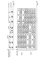
図3は、ガードバンドを付加した信号例を示す図であり、たとえば、マルチパス遅延時間が変化した場合の信号を示している。本実施の形態においては、一例として、8本のサブキャリアに2ユーザが周波数分割多重され、User1とUser2でそれぞれ異なったマルチパス遅延時間を有している場合を想定する。
FIG. 3 is a diagram illustrating an example of a signal to which a guard band is added. For example, the signal when the multipath delay time is changed is illustrated. In this embodiment, as an example, a case is assumed in which two users are frequency division multiplexed on eight subcarriers, and
たとえば、本実施の形態では、時間とともに変化する2ユーザのマルチパス遅延時間の最大値を等化するために十分なガードバンドを挿入する。図3においては、マルチパス遅延時間Lcの最大値が「大→中→大」と変化しているため、付加するガードバンド数LGBは、「ガードバンド:2箇所→ガードバンド:1箇所→ガードバンド:2箇所」と追従している。For example, in this embodiment, a sufficient guard band is inserted to equalize the maximum value of the multipath delay time of two users that changes with time. In FIG. 3, since the maximum value of the multipath delay time L c changes from “large → medium → large”, the number of guard bands L GB to be added is “guard band: 2 locations → guard bands: 1 location”. → Guard band: 2 places ”.
このように、本実施の形態においては、OFDMA方式に対応して、複数ユーザにおけるマルチパス遅延時間の最大値に応じてガードバンド量を変化させることとした。これにより、シンボル長を変化させない簡易なハードウェア構成で、到来するマルチパス遅延時間の変化に追従できる。 As described above, in the present embodiment, the guard band amount is changed according to the maximum value of the multipath delay time for a plurality of users in accordance with the OFDMA scheme. Thereby, it is possible to follow the change in the incoming multipath delay time with a simple hardware configuration that does not change the symbol length.
実施の形態3.
実施の形態3においては、前述した実施の形態1の特徴的な処理である「マルチパス遅延時間に応じてガードバンド量を変化させる」処理を、OFCDM(Orthogonal Frequency and Code Division Multiplexing)方式またはMC−CDMA(Multi-Carrier - Code Division Multiple Access)方式に適用する。なお、本実施の形態のシステム構成については、前述した実施の形態1の図1と同様である。ここでは、前述した実施の形態1と異なる処理について説明する。
In the third embodiment, the process of “changing the guard band amount according to the multipath delay time”, which is the characteristic process of the first embodiment described above, is performed in an OFCDM (Orthogonal Frequency and Code Division Multiplexing) method or MC. -Applies to CDMA (Multi-Carrier-Code Division Multiple Access) system. The system configuration of the present embodiment is the same as that of FIG. 1 of the first embodiment described above. Here, processing different from that of the first embodiment will be described.
図4は、ガードバンドを付加した信号例を示す図であり、たとえば、マルチパス遅延時間が変化した場合の信号を示している。本実施の形態においては、一例として、8本のサブキャリアに2ユーザが符号分割多重され、User1とUser2でそれぞれ異なったマルチパス遅延時間を有している場合を想定する。なお、図4において、下図の縦軸は、多重数(Multiplexing)を表し、奥行きは、周波数方向のサブキャリア(sub-carrier)を表している。
FIG. 4 is a diagram illustrating a signal example to which a guard band is added. For example, the signal when the multipath delay time is changed is illustrated. In the present embodiment, as an example, a case is assumed in which two users are code division multiplexed on eight subcarriers, and
たとえば、本実施の形態では、時間とともに変化する2ユーザのマルチパス遅延時間の最大値を等化するために十分なガードバンドを挿入する。図4においては、マルチパス遅延時間Lcの最大値が「大→中→大」と変化しているため、付加するガードバンド数LGBは、「ガードバンド:2箇所→ガードバンド:1箇所→ガードバンド:2箇所」と追従している。For example, in this embodiment, a sufficient guard band is inserted to equalize the maximum value of the multipath delay time of two users that changes with time. In FIG. 4, since the maximum value of the multipath delay time L c changes from “large → medium → large”, the number of guard bands L GB to be added is “guard band: 2 locations → guard bands: 1 location”. → Guard band: 2 places ”.
このように、本実施の形態においては、OFCDM方式またはMC−CDMA方式に対応して、複数ユーザにおけるマルチパス遅延時間の最大値に応じてガードバンド量を変化させることとした。これにより、シンボル長を変化させない簡易なハードウェア構成で、到来するマルチパス遅延時間の変化に追従できる。 Thus, in the present embodiment, the guard band amount is changed in accordance with the maximum value of the multipath delay time for a plurality of users, corresponding to the OFCDM system or the MC-CDMA system. Thereby, it is possible to follow the change in the incoming multipath delay time with a simple hardware configuration that does not change the symbol length.
実施の形態4.
図5は、本発明にかかる無線通信システムの構成例、すなわち、データ送信側の通信装置およびデータ受信側の通信装置の構成例を示す図であり、送信側の通信装置(変調器に相当)が、Data-Controlモジュール1aと、GB-Controlモジュール3aと、MCS-Controlモジュール7aを備え、受信側の通信装置(復調器に相当)が、GB-Controlモジュール13aと、Data-Controlモジュール15aと、MCS-Controlモジュール17aを備えている。なお、前述した実施の形態1の図1と同一の構成については、同一の符号を付してその説明を省略する。ここでは、前述した実施の形態1と異なる処理について説明する。
FIG. 5 is a diagram showing a configuration example of a radio communication system according to the present invention, that is, a configuration example of a data transmission side communication device and a data reception side communication device, and a transmission side communication device (corresponding to a modulator). Includes a Data-
本実施の形態において、MCS-Controlモジュール7a,17aは、変調符号化則(MCS:Modulation and Coding Scheme)の指示を行うモジュールであり、予め設定された変調符号化則に基づいて、Data-Controlモジュール1a,15aおよびGB-Controlモジュール3a,13aにパラメータ指示を与える。このとき、各MCS-Controlモジュールは、伝搬路のマルチパス遅延時間に応じて、各Data-ControlモジュールおよびGB-Controlモジュールを制御する。具体的には、たとえば、TDD(Time Division Duplex)システムの場合には、自局受信信号から伝搬路のマルチパス遅延時間を推定し、FDD(Frequency Division Duplex)システムの場合には、相手局においてマルチパス遅延時間を推定し、フィードバックされたマルチパス遅延時間を得る。そして、伝搬路のマルチパス遅延の増加に応じて通信品質が劣化することを利用して、フレーム誤り率,最小2乗距離等の通信品質を推定するパラメータに基づいて、間接的にデータサブキャリア,ガードバンドを制御する。
In the present embodiment, the MCS-
図6は、上記MCS-Controlモジュールで用いる変調符号化則の一例を示す図である。本実施の形態では、耐遅延能力を向上させるために、サブキャリア数を減少させ、ガードバンド数を増加させる制御を行う。なお、本実施の形態では、簡単化のために、ガードバンド数のみを軸に変調符号化則を作成しているが、変調方式,符号化率による変調符号化則を組み合わせることも可能である。 FIG. 6 is a diagram illustrating an example of a modulation and coding rule used in the MCS-Control module. In the present embodiment, in order to improve the delay tolerance, control is performed to decrease the number of subcarriers and increase the number of guard bands. In this embodiment, for the sake of simplicity, a modulation and coding rule is created with only the number of guard bands as an axis. However, a modulation and coding rule based on a modulation scheme and a coding rate can be combined. .
つづいて、上記ガードバンドの制御処理を行う場合の通信装置の動作を図面にしたがって説明する。本実施の形態の無線通信システムは、図5に示すとおり変調器と復調器により構成され、変復調器内のMCS-Controlモジュール7a,17aが、それぞれ伝搬路のマルチパス遅延時間に応じて適応的に変調符号化則を選択する。そして、この符号化則に基づいて、各MCS-Controlモジュールが、使用サブキャリア数をData-Controlモジュールへ、使用ガードバンド数をGB-Controlモジュールへ、それぞれ指示する。
Next, the operation of the communication apparatus when performing the guard band control process will be described with reference to the drawings. The radio communication system according to the present embodiment includes a modulator and a demodulator as shown in FIG. 5, and the MCS-
このように、本実施の形態においては、耐遅延能力を向上させるために、サブキャリア数を減少させ、ガードバンド数を増加させる制御を行うこととした。これにより、前述した実施の形態1と同様の効果に加えて、さらに、伝搬路のマルチパス遅延時間が増大する場合に、サブキャリア数減少に伴う情報伝送速度の低下のトレードオフとして、耐マルチパス遅延時間を向上させることができる。 Thus, in the present embodiment, in order to improve the delay tolerance, control is performed to decrease the number of subcarriers and increase the number of guard bands. As a result, in addition to the effects similar to those of the first embodiment described above, when the multipath delay time of the propagation path is further increased, as a trade-off of the decrease in the information transmission rate accompanying the decrease in the number of subcarriers, The path delay time can be improved.
実施の形態5.
図7は、本発明にかかる無線通信システムの構成例、すなわち、データ送信側の通信装置およびデータ受信側の通信装置の構成例を示す図であり、送信側の通信装置(変調器に相当)が、Rate-Controlモジュール8bを備え、受信側の通信装置(復調器に相当)が、Rate-Controlモジュール18bを備えている。なお、前述した実施の形態4の図5と同一の構成については、同一の符号を付してその説明を省略する。ここでは、前述した実施の形態5と異なる処理について説明する。Embodiment 5 FIG.
FIG. 7 is a diagram showing a configuration example of a wireless communication system according to the present invention, that is, a configuration example of a data transmission side communication device and a data reception side communication device, and a transmission side communication device (corresponding to a modulator). However, the rate-
たとえば、MCS-Controlモジュール7a,17aは、予め設定された変調符号化則に基づいて、Rate-Controlモジュール8b,18bおよびGB-Controlモジュール3a,13aに対してパラメータ指示を与える。そして、Rate-Controlモジュール8b,18bは、上記指示に基づいて、Dataモジュール2およびDecモジュール16で用いる符号化率を指示する。
For example, the MCS-
図8は、上記MCS-Controlモジュールで用いる変調符号化則の一例を示す図である。本実施の形態では、耐遅延能力を向上させるために、符号化率を増加させ、ガードバンド数を増加させる制御を行う。 FIG. 8 is a diagram illustrating an example of a modulation and coding rule used in the MCS-Control module. In this embodiment, in order to improve the delay tolerance, control is performed to increase the coding rate and increase the number of guard bands.
つづいて、上記ガードバンドの制御処理を行う場合の通信装置の動作を図面にしたがって説明する。図7に示すとおり変調器と復調器により構成され、変復調器内のMCS-Controlモジュール7a,17aが、それぞれ伝搬路に応じて適応的に変調符号化則を選択する。そして、この符号化則に基づいて、各MCS-Controlモジュールが、使用符号化率をRate-Controlモジュールへ、使用ガードバンド数をGB-Controlモジュールへ、それぞれ指示する。
Next, the operation of the communication apparatus when performing the guard band control process will be described with reference to the drawings. As shown in FIG. 7, the modulator and demodulator are configured, and the MCS-
このように、本実施の形態においては、耐遅延能力を向上させるために、符号化率を増加させ、ガードバンド数を増加させる制御を行うこととした。これにより、前述した実施の形態1と同様の効果に加えて、さらに、伝搬路のマルチパス遅延時間が増大する場合に、符号化率増加に伴う誤り訂正能力の低下のトレードオフとして、耐マルチパス遅延時間を向上させることができる。 Thus, in the present embodiment, in order to improve the delay tolerance, control is performed to increase the coding rate and increase the number of guard bands. As a result, in addition to the same effects as those of the first embodiment described above, when the multipath delay time of the propagation path is further increased, as a trade-off of a decrease in error correction capability accompanying an increase in coding rate, The path delay time can be improved.
以上のように、本発明にかかる無線通信システムおよび通信装置は、マルチキャリア変復調方式を採用する通信システムおよび通信装置に有用であり、特に、伝搬路のマルチパス遅延時間が変化する通信環境で動作するデータ送信側の通信装置およびデータ受信側の通信装置に適している。 As described above, the wireless communication system and the communication apparatus according to the present invention are useful for a communication system and a communication apparatus that employ a multicarrier modulation / demodulation method, and particularly operate in a communication environment in which a multipath delay time of a propagation path changes. It is suitable for a communication device on the data transmission side and a communication device on the data reception side.
Claims (7)
送信側の通信装置が、
自装置の受信信号に基づく所定の推定処理により得られる伝搬路のマルチパス遅延時間に基づいて、データサブキャリアに対してマッピング処理を実行するマッピング手段と、
前記マルチパス遅延時間により得られるガードバンドに関する情報に応じて、データサブキャリア上の信号に付加するガードバンド量を変化させるガードバンド付加手段と、
ガードバンド付加後の周波数軸信号を時間軸信号へ変換する逆フーリエ変換手段と、
前記時間軸信号にガードインターバルを付加するガードインターバル付加手段と、
を備え、
受信側の通信装置が、
受信信号である時間軸信号からガードインターバルを除去することにより、ガードインターバル内におけるマルチパスを除去するガードインターバル除去手段と、
ガードインターバル除去後の時間軸信号を周波数軸信号に変換して出力するフーリエ変換手段と、
前記フーリエ変換手段により出力された周波数軸信号を入力し、前記マルチパス遅延時間により得られるガードバンドに関する情報に基づいて、前記ガードインターバル除去手段により除去されたガードインターバルを超える遅延波として当該周波数軸信号に含まれるマルチパスを抑圧する等化手段と、
前記マルチパス遅延時間に基づいて、等化後の信号に対してデマッピング処理を実行するデマッピング手段と、
を備え、
前記送信側の通信装置におけるガードバンド付加手段は、
マルチパス遅延時間の増加に伴ってガードバンド量を増大させ、
さらに、複数ユーザにおけるマルチパス遅延時間の最大値の増加に伴ってガードバンド量を増大させる、
ことを特徴とする無線通信システム。 A TDD wireless communication system employing a multicarrier modulation / demodulation method,
The sending communication device is
Mapping means for performing mapping processing on the data subcarrier based on the multipath delay time of the propagation path obtained by the predetermined estimation processing based on the received signal of the own device;
Guard band adding means for changing a guard band amount to be added to a signal on a data subcarrier according to information on the guard band obtained by the multipath delay time;
Inverse Fourier transform means for transforming the frequency axis signal after adding the guard band into a time axis signal;
Guard interval adding means for adding a guard interval to the time axis signal;
With
The communication device on the receiving side
Guard interval removing means for removing multipaths in the guard interval by removing the guard interval from the time axis signal that is a received signal;
Fourier transform means for converting the time axis signal after the guard interval removal into a frequency axis signal and outputting it,
The frequency axis signal output by the Fourier transform unit is input, and based on the information on the guard band obtained by the multipath delay time, the frequency axis as a delayed wave exceeding the guard interval removed by the guard interval removing unit Equalization means for suppressing multipath included in the signal;
Demapping means for performing demapping processing on the equalized signal based on the multipath delay time;
With
The guard band adding means in the transmission side communication device is:
Increase the amount of guard band with increasing multipath delay time,
Furthermore, the amount of guard bands is increased as the maximum value of the multipath delay time in a plurality of users is increased .
A wireless communication system.
送信側の通信装置が、
自装置の受信信号に基づく所定の推定処理により得られる伝搬路のマルチパス遅延時間に基づいて、データサブキャリアに対してマッピング処理を実行するマッピング手段と、
前記マルチパス遅延時間により得られるガードバンドに関する情報に応じて、データサブキャリア上の信号に付加するガードバンド量を変化させるガードバンド付加手段と、
ガードバンド付加後の周波数軸信号を時間軸信号へ変換する逆フーリエ変換手段と、
前記時間軸信号にガードインターバルを付加するガードインターバル付加手段と、
を備え、
受信側の通信装置が、
受信信号である時間軸信号からガードインターバルを除去することにより、ガードインターバル内におけるマルチパスを除去するガードインターバル除去手段と、
ガードインターバル除去後の時間軸信号を周波数軸信号に変換して出力するフーリエ変換手段と、
前記フーリエ変換手段により出力された周波数軸信号を入力し、前記マルチパス遅延時間により得られるガードバンドに関する情報に基づいて、前記ガードインターバル除去手段により除去されたガードインターバルを超える遅延波として当該周波数軸信号に含まれるマルチパスを抑圧する等化手段と、
前記マルチパス遅延時間に基づいて、等化後の信号に対してデマッピング処理を実行するデマッピング手段と、
を備え、
前記送信側および前記受信側の通信装置が、
さらに、前記マルチパス遅延時間に応じて適応的に変調符号化則を選択する変調符号化則選択手段、
をそれぞれ備え、
前記送信側および受信側の通信装置における各手段は、前記マルチパス遅延時間に応じて選択された変調符号化則に基づいた処理を実行する、
ことを特徴とする無線通信システム。 A TDD wireless communication system employing a multicarrier modulation / demodulation method,
The sending communication device is
Mapping means for performing mapping processing on the data subcarrier based on the multipath delay time of the propagation path obtained by the predetermined estimation processing based on the received signal of the own device;
Guard band adding means for changing a guard band amount to be added to a signal on a data subcarrier according to information on the guard band obtained by the multipath delay time;
Inverse Fourier transform means for transforming the frequency axis signal after adding the guard band into a time axis signal;
Guard interval adding means for adding a guard interval to the time axis signal;
With
The communication device on the receiving side
Guard interval removing means for removing multipaths in the guard interval by removing the guard interval from the time axis signal that is a received signal;
Fourier transform means for converting the time axis signal after the guard interval removal into a frequency axis signal and outputting it,
The frequency axis signal output by the Fourier transform unit is input, and based on the information on the guard band obtained by the multipath delay time, the frequency axis as a delayed wave exceeding the guard interval removed by the guard interval removing unit Equalization means for suppressing multipath included in the signal;
Demapping means for performing demapping processing on the equalized signal based on the multipath delay time;
With
The communication device on the transmission side and the reception side,
Further, a modulation and coding rule selection means for adaptively selecting a modulation and coding rule according to the multipath delay time,
Each with
Each means in the communication device on the transmission side and the reception side executes processing based on a modulation and coding rule selected according to the multipath delay time .
A wireless communication system.
データ受信側の通信装置から受信した信号に基づく所定の推定処理により得られる伝搬路のマルチパス遅延時間に基づいて、データサブキャリアに対してマッピング処理を実行するマッピング手段と、
前記マルチパス遅延時間により得られるガードバンドに関する情報に応じて、データサブキャリア上の信号に付加するガードバンド量を変化させるガードバンド付加手段と、
ガードバンド付加後の周波数軸信号を時間軸信号へ変換する逆フーリエ変換手段と、
前記時間軸信号にガードインターバルを付加するガードインターバル付加手段と、
を備え、
前記ガードバンド付加手段は、
マルチパス遅延時間の増加に伴ってガードバンド量を増大させ、
さらに、複数ユーザにおけるマルチパス遅延時間の最大値の増加に伴ってガードバンド量を増大させる、
ことを特徴とする通信装置。 A data transmission side communication device constituting a TDD wireless communication system employing a multicarrier modulation / demodulation method,
Mapping means for performing mapping processing on data subcarriers based on a multipath delay time of a propagation path obtained by predetermined estimation processing based on a signal received from a communication device on the data receiving side;
Guard band adding means for changing a guard band amount to be added to a signal on a data subcarrier according to information on the guard band obtained by the multipath delay time;
Inverse Fourier transform means for transforming the frequency axis signal after adding the guard band into a time axis signal;
Guard interval adding means for adding a guard interval to the time axis signal;
With
The guard band adding means includes
Increase the amount of guard band with increasing multipath delay time,
Furthermore, the amount of guard bands is increased as the maximum value of the multipath delay time in a plurality of users is increased .
A communication device.
データ受信側の通信装置から受信した信号に基づく所定の推定処理により得られる伝搬路のマルチパス遅延時間に基づいて、データサブキャリアに対してマッピング処理を実行するマッピング手段と、
前記マルチパス遅延時間により得られるガードバンドに関する情報に応じて、データサブキャリア上の信号に付加するガードバンド量を変化させるガードバンド付加手段と、
ガードバンド付加後の周波数軸信号を時間軸信号へ変換する逆フーリエ変換手段と、
前記時間軸信号にガードインターバルを付加するガードインターバル付加手段と、
を備え、
さらに、前記マルチパス遅延時間に応じて適応的に変調符号化則を選択する変調符号化則選択手段、
を備え、
前記各手段は、前記マルチパス遅延時間に応じて選択された変調符号化則に基づいた処理を実行する、
ことを特徴とする通信装置。 A data transmission side communication device constituting a TDD wireless communication system employing a multicarrier modulation / demodulation method,
Mapping means for performing mapping processing on data subcarriers based on a multipath delay time of a propagation path obtained by predetermined estimation processing based on a signal received from a communication device on the data receiving side;
Guard band adding means for changing a guard band amount to be added to a signal on a data subcarrier according to information on the guard band obtained by the multipath delay time;
Inverse Fourier transform means for transforming the frequency axis signal after adding the guard band into a time axis signal;
Guard interval adding means for adding a guard interval to the time axis signal;
With
Further, a modulation and coding rule selection means for adaptively selecting a modulation and coding rule according to the multipath delay time,
With
Each means executes processing based on a modulation and coding rule selected according to the multipath delay time ;
A communication device.
請求項6に記載の送信側の通信装置から受信した信号である時間軸信号からガードインターバルを除去することにより、ガードインターバル内におけるマルチパスを除去するガードインターバル除去手段と、
ガードインターバル除去後の時間軸信号を周波数軸信号に変換して出力するフーリエ変換手段と、
前記フーリエ変換手段により出力された周波数軸信号を入力し、伝搬路のマルチパス遅延時間により得られるガードバンドに関する情報に基づいて、前記ガードインターバル除去手段により除去されたガードインターバルを超える遅延波として当該周波数軸信号に含まれるマルチパスを抑圧する等化手段と、
前記マルチパス遅延時間に基づいて、等化後の周波数信号に対してデマッピング処理を実行するデマッピング手段と、
を備え、
さらに、前記マルチパス遅延時間に応じて適応的に変調符号化則を選択する変調符号化則選択手段、
を備え、
前記各手段は、前記マルチパス遅延時間に応じて選択された変調符号化則に基づいた処理を実行する、
ことを特徴とする通信装置。 A data reception side communication apparatus constituting a TDD wireless communication system employing a multicarrier modulation / demodulation system,
Guard interval removing means for removing multipaths within the guard interval by removing the guard interval from the time axis signal that is a signal received from the communication device on the transmission side according to claim 6;
Fourier transform means for converting the time axis signal after the guard interval removal into a frequency axis signal and outputting it,
As a delayed wave exceeding the guard interval removed by the guard interval removing means based on the information on the guard band obtained by the multipath delay time of the propagation path by inputting the frequency axis signal outputted by the Fourier transform means Equalization means for suppressing multipath included in the frequency axis signal;
Demapping means for performing demapping processing on the frequency signal after equalization based on the multipath delay time;
With
Further, a modulation and coding rule selection means for adaptively selecting a modulation and coding rule according to the multipath delay time,
With
Each means executes processing based on a modulation and coding rule selected according to the multipath delay time ;
A communication device.
Applications Claiming Priority (1)
| Application Number | Priority Date | Filing Date | Title |
|---|---|---|---|
| PCT/JP2005/015278 WO2007023530A1 (en) | 2005-08-23 | 2005-08-23 | Wireless communication system and communication apparatus |
Publications (2)
| Publication Number | Publication Date |
|---|---|
| JPWO2007023530A1 JPWO2007023530A1 (en) | 2009-02-26 |
| JP4611385B2 true JP4611385B2 (en) | 2011-01-12 |
Family
ID=37771288
Family Applications (1)
| Application Number | Title | Priority Date | Filing Date |
|---|---|---|---|
| JP2007531974A Active JP4611385B2 (en) | 2005-08-23 | 2005-08-23 | Wireless communication system and communication apparatus |
Country Status (6)
| Country | Link |
|---|---|
| US (1) | US8265179B2 (en) |
| EP (1) | EP1919111A4 (en) |
| JP (1) | JP4611385B2 (en) |
| KR (1) | KR100924187B1 (en) |
| CN (1) | CN101223717B (en) |
| WO (1) | WO2007023530A1 (en) |
Families Citing this family (9)
| Publication number | Priority date | Publication date | Assignee | Title |
|---|---|---|---|---|
| US9055552B2 (en) | 2005-06-16 | 2015-06-09 | Qualcomm Incorporated | Quick paging channel with reduced probability of missed page |
| US20070147226A1 (en) * | 2005-10-27 | 2007-06-28 | Aamod Khandekar | Method and apparatus for achieving flexible bandwidth using variable guard bands |
| JP2009514429A (en) | 2005-10-27 | 2009-04-02 | クゥアルコム・インコーポレイテッド | Method and apparatus for transmitting an access probe in a wireless communication system |
| EP2043314A1 (en) * | 2007-09-25 | 2009-04-01 | Thomson Licensing, Inc. | A self-adaptive frequency interpolator for use in a multi-carrier receiver |
| CN101621366B (en) * | 2008-07-01 | 2012-11-14 | 富士通株式会社 | Adaptive transmission method and system for radio communication system |
| JP5822215B2 (en) * | 2010-10-13 | 2015-11-24 | マーベル ワールド トレード リミテッド | Method and apparatus for generating OFDM symbols |
| KR20150064595A (en) * | 2013-12-03 | 2015-06-11 | 한국전자통신연구원 | Method for transmitting data by using variable guard interval and apparatus thereof |
| WO2015177923A1 (en) * | 2014-05-23 | 2015-11-26 | 三菱電機株式会社 | Communication device, communication method and program |
| CN108024356B (en) * | 2016-11-04 | 2021-12-28 | 华为技术有限公司 | Transmission method and device |
Citations (8)
| Publication number | Priority date | Publication date | Assignee | Title |
|---|---|---|---|---|
| JPH11215095A (en) * | 1998-01-28 | 1999-08-06 | Jisedai Digital Television Hoso System Kenkyusho:Kk | Ofdm signal transmitter |
| JP2001028577A (en) * | 1999-07-14 | 2001-01-30 | Sumitomo Electric Ind Ltd | Inter-road vehicle communication system, on-road communication station and on-vehicle mobile station |
| JP2002141879A (en) * | 2000-11-01 | 2002-05-17 | Matsushita Electric Ind Co Ltd | Device and method for radio transmitting |
| JP2003152597A (en) * | 2001-11-09 | 2003-05-23 | Ntt Docomo Inc | Transmission system, method and apparatus for transmission and electronic recording medium recording transmission program |
| JP2003188847A (en) * | 2001-09-27 | 2003-07-04 | Toyota Central Res & Dev Lab Inc | Multicarrier demodulating method and apparatus |
| JP2004207901A (en) * | 2002-12-24 | 2004-07-22 | Matsushita Electric Ind Co Ltd | Wireless transmission apparatus and wireless transmission method |
| WO2006092877A1 (en) * | 2005-03-02 | 2006-09-08 | Mitsubishi Denki Kabushiki Kaisha | Receiver apparatus |
| JP2006311234A (en) * | 2005-04-28 | 2006-11-09 | Nec Corp | Radio communication system, radio communication equipment, receiver and radio communication method |
Family Cites Families (18)
| Publication number | Priority date | Publication date | Assignee | Title |
|---|---|---|---|---|
| US6810070B1 (en) * | 2000-01-12 | 2004-10-26 | Ericsson Inc. | Selective multi-carrier direct sequence spread spectrum communication systems and methods |
| JP2001345780A (en) * | 2000-06-06 | 2001-12-14 | Sony Corp | Ofdm receiving device using maximum ratio synthesization diversity |
| JP3628977B2 (en) * | 2001-05-16 | 2005-03-16 | 松下電器産業株式会社 | Radio base station apparatus and communication terminal apparatus |
| JP4644978B2 (en) | 2001-06-15 | 2011-03-09 | パナソニック株式会社 | OFDM communication system, OFDM communication method, and OFDM communication apparatus |
| US7126996B2 (en) * | 2001-12-28 | 2006-10-24 | Motorola, Inc. | Adaptive transmission method |
| US7463577B2 (en) * | 2002-04-09 | 2008-12-09 | Panasonic Corporation | OFDM communication method and OFDM communication device |
| JP3986929B2 (en) * | 2002-08-27 | 2007-10-03 | 富士通株式会社 | Leakage electromagnetic field suppression transmission method and leakage electromagnetic field suppression transmission apparatus in power line carrier communication |
| JP4381749B2 (en) | 2002-09-19 | 2009-12-09 | パナソニック株式会社 | Wireless communication apparatus and wireless communication method |
| EP1605619A4 (en) * | 2003-02-28 | 2012-01-11 | Ntt Docomo Inc | Radio communication system and radio communication method |
| JP4482293B2 (en) | 2003-07-03 | 2010-06-16 | パナソニック株式会社 | Base station apparatus and transmission method |
| KR101055004B1 (en) * | 2003-07-31 | 2011-08-05 | 파나소닉 주식회사 | Radio transmitter apparatus and modulation scheme selecting method |
| KR20050050322A (en) * | 2003-11-25 | 2005-05-31 | 삼성전자주식회사 | Method for adptive modulation in a ofdma mobile communication system |
| KR20050053907A (en) * | 2003-12-03 | 2005-06-10 | 삼성전자주식회사 | Method for assigning sub-carrier in a mobile communication system using orthogonal frequency division multiple access scheme |
| US7339999B2 (en) * | 2004-01-21 | 2008-03-04 | Qualcomm Incorporated | Pilot transmission and channel estimation for an OFDM system with excess delay spread |
| JP4418377B2 (en) | 2004-01-29 | 2010-02-17 | パナソニック株式会社 | Communication terminal device and base station device |
| US8577299B2 (en) * | 2004-06-04 | 2013-11-05 | Qualcomm Incorporated | Wireless communication system with configurable cyclic prefix length |
| US7630465B2 (en) * | 2004-11-23 | 2009-12-08 | Harris Corporation | Wireless communications device providing time and frequency-domain channel estimates interpolation and related methods |
| US7881390B2 (en) * | 2004-12-01 | 2011-02-01 | Intel Corporation | Increased discrete point processing in an OFDM communication system |
-
2005
- 2005-08-23 KR KR1020087004176A patent/KR100924187B1/en not_active IP Right Cessation
- 2005-08-23 EP EP05774910A patent/EP1919111A4/en not_active Withdrawn
- 2005-08-23 CN CN2005800510944A patent/CN101223717B/en not_active Expired - Fee Related
- 2005-08-23 JP JP2007531974A patent/JP4611385B2/en active Active
- 2005-08-23 US US11/994,853 patent/US8265179B2/en not_active Expired - Fee Related
- 2005-08-23 WO PCT/JP2005/015278 patent/WO2007023530A1/en active Application Filing
Patent Citations (8)
| Publication number | Priority date | Publication date | Assignee | Title |
|---|---|---|---|---|
| JPH11215095A (en) * | 1998-01-28 | 1999-08-06 | Jisedai Digital Television Hoso System Kenkyusho:Kk | Ofdm signal transmitter |
| JP2001028577A (en) * | 1999-07-14 | 2001-01-30 | Sumitomo Electric Ind Ltd | Inter-road vehicle communication system, on-road communication station and on-vehicle mobile station |
| JP2002141879A (en) * | 2000-11-01 | 2002-05-17 | Matsushita Electric Ind Co Ltd | Device and method for radio transmitting |
| JP2003188847A (en) * | 2001-09-27 | 2003-07-04 | Toyota Central Res & Dev Lab Inc | Multicarrier demodulating method and apparatus |
| JP2003152597A (en) * | 2001-11-09 | 2003-05-23 | Ntt Docomo Inc | Transmission system, method and apparatus for transmission and electronic recording medium recording transmission program |
| JP2004207901A (en) * | 2002-12-24 | 2004-07-22 | Matsushita Electric Ind Co Ltd | Wireless transmission apparatus and wireless transmission method |
| WO2006092877A1 (en) * | 2005-03-02 | 2006-09-08 | Mitsubishi Denki Kabushiki Kaisha | Receiver apparatus |
| JP2006311234A (en) * | 2005-04-28 | 2006-11-09 | Nec Corp | Radio communication system, radio communication equipment, receiver and radio communication method |
Also Published As
| Publication number | Publication date |
|---|---|
| CN101223717B (en) | 2011-09-21 |
| EP1919111A4 (en) | 2010-03-24 |
| JPWO2007023530A1 (en) | 2009-02-26 |
| US20080205455A1 (en) | 2008-08-28 |
| KR20080022237A (en) | 2008-03-10 |
| EP1919111A1 (en) | 2008-05-07 |
| CN101223717A (en) | 2008-07-16 |
| KR100924187B1 (en) | 2009-10-29 |
| US8265179B2 (en) | 2012-09-11 |
| WO2007023530A1 (en) | 2007-03-01 |
Similar Documents
| Publication | Publication Date | Title |
|---|---|---|
| JP4611385B2 (en) | Wireless communication system and communication apparatus | |
| US10476544B2 (en) | Signal transmission and receiving method, system and apparatus based on filter bank | |
| KR101139170B1 (en) | Method and apparatus for transmitting/receiving packet data control channel in wireless communication system using ofdma | |
| JP5393641B2 (en) | Communication apparatus and communication method | |
| CN107306238B (en) | Method for receiving and transmitting carrier modulation signals, and corresponding receiver and transmitter | |
| US10701685B2 (en) | Method and apparatus for asynchronous OFDMA/SC-FDMA | |
| WO2006118726A2 (en) | Method and apparatus for constant envelope orthogonal frequency division multiplexing in a wireless system | |
| KR20110076962A (en) | Efficient multiplexing of reference signal and data in a wireless communication system | |
| US7443782B2 (en) | Adaptive inter-carrier interference self-cancellation method and transceiver thereof | |
| US20060198472A1 (en) | Transmission system, transmitter device, and receiver device | |
| WO2007088580A1 (en) | Communication control method, receiving station apparatus, transmitting station apparatus, and communication system | |
| KR101093346B1 (en) | Apparatus and method for transmitting ofdma symbol | |
| JP5254526B2 (en) | System, modem, receiver, transmitter and method for improving transmission performance | |
| KR100790484B1 (en) | Partial response signaling for orthogonal frequency division multiplexing | |
| Ahmed et al. | Coexistence of UF-OFDM and CP-OFDM | |
| WO2018036333A1 (en) | Complexity reduction for ofdm signal transmissions | |
| US10103906B2 (en) | Method and apparatus for attenuating interference or cancelling interference in filter bank multicarrier system | |
| JP4675790B2 (en) | Communication apparatus and communication system | |
| WO2017167386A1 (en) | A transmitter for transmitting and a receiver for receiving a plurality of multicarrier modulation signals | |
| WO2021057628A1 (en) | System and method for transmitting and receiving single-carrier oqam symbols with non-nyquist transmit pulse shaping | |
| CN114450924B (en) | System and method for transmitting and receiving single carrier OQAM symbols pulse shaped by non-Nyquist transmission | |
| Singh | A DFT based channel estimation technique in orthogonal-frequency division-multiplexing (OFDM): A Review | |
| US20230308335A1 (en) | Methods and apparatus for using a phase tracking reference signal with a single carrier waveform | |
| KR101385973B1 (en) | Apparatus and method for uplink adaptive pilot signal space switching in an orthogonal frequency division multiplexing wireless system | |
| KR20080112578A (en) | Apparatus and method for improving spectral efficiency of orthogonal frequency division multiplexing access |
Legal Events
| Date | Code | Title | Description |
|---|---|---|---|
| A131 | Notification of reasons for refusal |
Free format text: JAPANESE INTERMEDIATE CODE: A131 Effective date: 20100126 |
|
| A521 | Request for written amendment filed |
Free format text: JAPANESE INTERMEDIATE CODE: A523 Effective date: 20100329 |
|
| A02 | Decision of refusal |
Free format text: JAPANESE INTERMEDIATE CODE: A02 Effective date: 20100511 |
|
| A521 | Request for written amendment filed |
Free format text: JAPANESE INTERMEDIATE CODE: A523 Effective date: 20100803 |
|
| A911 | Transfer to examiner for re-examination before appeal (zenchi) |
Free format text: JAPANESE INTERMEDIATE CODE: A911 Effective date: 20100818 |
|
| TRDD | Decision of grant or rejection written | ||
| A01 | Written decision to grant a patent or to grant a registration (utility model) |
Free format text: JAPANESE INTERMEDIATE CODE: A01 Effective date: 20101012 |
|
| A01 | Written decision to grant a patent or to grant a registration (utility model) |
Free format text: JAPANESE INTERMEDIATE CODE: A01 |
|
| A61 | First payment of annual fees (during grant procedure) |
Free format text: JAPANESE INTERMEDIATE CODE: A61 Effective date: 20101013 |
|
| FPAY | Renewal fee payment (event date is renewal date of database) |
Free format text: PAYMENT UNTIL: 20131022 Year of fee payment: 3 |
|
| R150 | Certificate of patent or registration of utility model |
Ref document number: 4611385 Country of ref document: JP Free format text: JAPANESE INTERMEDIATE CODE: R150 Free format text: JAPANESE INTERMEDIATE CODE: R150 |
|
| R250 | Receipt of annual fees |
Free format text: JAPANESE INTERMEDIATE CODE: R250 |
|
| R250 | Receipt of annual fees |
Free format text: JAPANESE INTERMEDIATE CODE: R250 |
|
| R250 | Receipt of annual fees |
Free format text: JAPANESE INTERMEDIATE CODE: R250 |
|
| R250 | Receipt of annual fees |
Free format text: JAPANESE INTERMEDIATE CODE: R250 |
|
| R250 | Receipt of annual fees |
Free format text: JAPANESE INTERMEDIATE CODE: R250 |
|
| R250 | Receipt of annual fees |
Free format text: JAPANESE INTERMEDIATE CODE: R250 |
|
| R250 | Receipt of annual fees |
Free format text: JAPANESE INTERMEDIATE CODE: R250 |
|
| R250 | Receipt of annual fees |
Free format text: JAPANESE INTERMEDIATE CODE: R250 |
|
| R250 | Receipt of annual fees |
Free format text: JAPANESE INTERMEDIATE CODE: R250 |