JP5334635B2 - Bearing fixing structure - Google Patents
Bearing fixing structure Download PDFInfo
- Publication number
- JP5334635B2 JP5334635B2 JP2009060885A JP2009060885A JP5334635B2 JP 5334635 B2 JP5334635 B2 JP 5334635B2 JP 2009060885 A JP2009060885 A JP 2009060885A JP 2009060885 A JP2009060885 A JP 2009060885A JP 5334635 B2 JP5334635 B2 JP 5334635B2
- Authority
- JP
- Japan
- Prior art keywords
- bolt
- coupler
- anchor bolt
- support
- fixing structure
- Prior art date
- Legal status (The legal status is an assumption and is not a legal conclusion. Google has not performed a legal analysis and makes no representation as to the accuracy of the status listed.)
- Expired - Fee Related
Links
- 239000000463 material Substances 0.000 claims description 2
- 239000000945 filler Substances 0.000 description 4
- 238000009434 installation Methods 0.000 description 3
- 238000003466 welding Methods 0.000 description 3
- 238000000034 method Methods 0.000 description 2
- XLYOFNOQVPJJNP-UHFFFAOYSA-N water Substances O XLYOFNOQVPJJNP-UHFFFAOYSA-N 0.000 description 2
- 235000014676 Phragmites communis Nutrition 0.000 description 1
- 230000015572 biosynthetic process Effects 0.000 description 1
- 239000002775 capsule Substances 0.000 description 1
- 239000000470 constituent Substances 0.000 description 1
- 238000010276 construction Methods 0.000 description 1
- 238000005260 corrosion Methods 0.000 description 1
- 230000007797 corrosion Effects 0.000 description 1
- 239000004570 mortar (masonry) Substances 0.000 description 1
- 239000013585 weight reducing agent Substances 0.000 description 1
Images


Landscapes
- Bridges Or Land Bridges (AREA)
Description
本発明は、建築物や橋梁等の構造物の上部構造と下部構造の間に配置される支承装置を、上部構造又は下部構造に配されるアンカーボルトを介して固定する支承固定構造に関する。 The present invention relates to a support fixing structure for fixing a support device arranged between an upper structure and a lower structure of a structure such as a building or a bridge via an anchor bolt arranged in the upper structure or the lower structure.
支承装置を構造物に固定する支承固定構造として、上部構造又は下部構造に埋設固定されるアンカーボルトの先端に形成した雄ねじ部を支承取付用プレートに形成した取付穴に挿通し、アンカーボルトの先端に形成した雄ねじ部に座金を介してナットを螺着して固定する固定構造や、取付穴に雌ねじを形成しアンカーボルトの先端部に形成した雄ねじ部を雌ねじ取付穴の雌ねじに直接螺着し固定する固定構造や、支承取付用プレートとアンカーボルトを段付きカプラーと溶接手段を介して固定するものがある。 Insert the male screw part formed at the tip of the anchor bolt embedded and fixed in the upper structure or lower structure into the mounting hole formed in the support mounting plate as the support fixing structure that fixes the support device to the structure, and the tip of the anchor bolt A fixing structure in which a nut is screwed and fixed to a male screw part formed through a washer, and a male screw part formed at the tip of an anchor bolt is directly screwed onto a female screw in a female screw mounting hole. There is a fixing structure for fixing, and a structure for fixing a support mounting plate and an anchor bolt via a stepped coupler and welding means.
しかしながら、アンカーボルトの先端に形成した雄ねじ部を支承取付用プレートに形成した取付穴に挿通し、アンカーボルトの先端に形成した雄ねじ部に座金を介してナットを螺着して固定する固定構造は、アンカーボルトの先端の雄ねじ部と取付穴との間に間隙が形成されるため地震時の水平力に対する抵抗力が弱く、さらに、アンカーボルト先端部の雄ねじ部の外径が取付穴の内径より小さいため、座金とナットでアンカーボルトと螺着後、座金と支承装置取付用プレートを溶接により固定する必要があり、支承装置の設置、取替えのための撤去作業が困難になるという問題を有する。 However, there is a fixing structure in which the male screw part formed at the tip of the anchor bolt is inserted into the mounting hole formed in the support mounting plate and the nut is screwed and fixed to the male screw part formed at the tip of the anchor bolt via a washer. In addition, since a gap is formed between the male screw at the tip of the anchor bolt and the mounting hole, resistance to horizontal force during an earthquake is weak, and the outer diameter of the male screw at the tip of the anchor bolt is smaller than the inner diameter of the mounting hole. Since it is small, it is necessary to fix the washer and the support device mounting plate by welding after screwing the anchor bolt with the washer and nut, and there is a problem that it is difficult to remove the installation and replacement of the support device.
また、取付穴に雌ねじを形成しアンカーボルトの先端部に形成した雄ねじ部を取付穴の雌ねじに直接螺着し固定する固定構造は、地震時の水平力に対向するため、螺着長さが必要であり、そのため支承取付用プレートの板厚を厚くしなければならず、軽量化が望まれる支承装置の重量を増加させるという問題と、支承装置の取替えのための撤去作業が困難であるという問題を有する。 In addition, the fixing structure in which a female thread is formed in the mounting hole and the male thread formed on the tip of the anchor bolt is directly screwed to the female thread in the mounting hole is fixed to the horizontal force in the event of an earthquake. Therefore, it is necessary to increase the thickness of the plate for mounting the support, which increases the weight of the support device for which weight reduction is desired, and the removal work for replacing the support device is difficult. Have a problem.
支承取付用プレートとアンカーボルトを段付きカプラーと溶接手段を介して固定する固定構造は、支承装置の取替えのための撤去作業の際、アンカーボルトを埋設固定しているコンクリートのはつり作業が必要になるという問題を有する。 The fixing structure for fixing the support mounting plate and anchor bolts via stepped couplers and welding means requires that the concrete that anchors the anchor bolts to be buried is removed when removing the support device for replacement. Have the problem of becoming.
本発明は、上記従来技術の持つ課題を解決する、構造が簡単で支承取付用プレートとアンカーボルトの固定作業が容易で、地震時の水平力、上揚力に対する抵抗性が大きく、支承装置取替えのための撤去作業も容易にできる支承固定構造を提供することを目的とする。 The present invention solves the above-mentioned problems of the prior art, has a simple structure, facilitates the fixing work of the support mounting plate and the anchor bolt, has high resistance to horizontal force and uplift during an earthquake, and can be used to replace the support device. An object of the present invention is to provide a support fixing structure that can be easily removed.
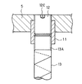
本発明の支承固定構造は、前記課題を解決するために、下部にアンカーボルト用雌ねじ部11Bと上部に上揚力対応ボルト用雌ねじ部11Aを有し、前記アンカーボルト用雌ねじ穴と前記上楊力対応ボルト用雌ねじ穴の内径が異なり前記アンカーボルト用雌ねじ穴と前記上楊力対応ボルト用雌ねじ穴とを連通状態又は非連通状態とした円筒形のカプラー11と、外周に雄ねじ部12Aを有し上端面に回動工具係合凹部12Cを有する上揚力対応ボルト12と、先端部に前記アンカーボルト用雌ねじ穴に螺着される雄ねじ部13Aを形成したアンカーボルト13と、上揚力対応ボルト用雌ねじ部を有する小径部10Aと前記小径部と段部を介して連通する前記カプラーの外径とほぼ同じ内径の大径部10Bを有する取付穴10を形成した支承取付用プレート5と、を備え、前記アンカーボルトの先端雄ねじ部をアンカーボルト用雌ねじ部に螺着した前記カプラーを前記取付穴の前記大径部に配し、前記上揚力対応ボルトを前記取付穴の小径部の上揚力対応ボルト用雌ねじ部と前記カプラーの上揚力対応ボルト用雌ねじ部に渡って螺着し固定することを特徴とする。
In order to solve the above problems , the bearing fixing structure of the present invention has a
また、本発明の支承固定構造は、前記上揚力対応ボルトの上端面が前記支承取付用プレートの表面と同一面になるよう固定することを特徴とする。 Further, the bearing fixing structure of the present invention is characterized in that the upper end face of the upper lifting force corresponding bolt is fixed so as to be flush with the surface of the bearing mounting plate.
また、本発明の支承固定構造は、固定時に前記上揚力対応ボルトの回動工具係合凹部に除去可能な充填材を充填することを特徴とする。 Further, the bearing fixing structure of the present invention is characterized in that a filling material that can be removed is filled into the rotating tool engaging concave portion of the upper lifting force corresponding bolt at the time of fixing.
本発明の、下部にアンカーボルト用雌ねじ部と上部に上揚力対応ボルト用雌ねじ部を有し、前記アンカーボルト用雌ねじ穴と前記上楊力対応ボルト用雌ねじ穴の内径が異なり前記アンカーボルト用雌ねじ穴と前記上楊力対応ボルト用雌ねじ穴とを連通状態又は非連通状態とした円筒形のカプラーと、外周に雄ねじ部を有し上端面に回動工具係合凹部を有する上揚力対応ボルト、先端部に前記アンカーボルト用雌ねじ穴に螺着される雄ねじ部を形成したアンカーボルトと、上揚力対応ボルト用雌ねじ部を有する小径部と前記小径部と段部を介して連通する前記カプラーの外径とほぼ同じ内径の大径部を有する取付穴を形成した支承取付用プレートと、を備え、前記アンカーボルトの先端雄ねじ部をアンカーボルト用雌ねじ部に螺着した前記カプラーを前記取付穴の前記大径部に配し、前記上揚力対応ボルトを前記取付穴の小径部の上揚力対応ボルト用雌ねじ部と前記カプラーの上揚力対応ボルト用雌ねじ部に渡って螺着し固定する構成により、取付穴の小径部の雌ねじ部とカプラーの雌ねじ部に渡って螺着される上揚力対応ボルトが地震時の上揚力に対して抵抗でき、上揚力対応ボルトの先端面の回動工具係合凹部が形成されているため、支承装置の設置、撤去作業を上揚力対応ボルトの回動操作のみで実施でき、アンカーボルト及び上揚力対応ボルトの螺着長を正確に設定できる。
上揚力対応ボルトの上端面が支承取付用プレートの表面と同一面になるよう固定する構成により、支承取付用プレートに邪魔な突起部が形成されないため他の支承装置の構成部材の配置が容易になる。
固定時に前記上揚力ボルトの回動工具係合凹部に除去可能な充填材を充填する構成により、回動工具係合凹部に水等が溜まり腐食するのを防止できる。
The anchor bolt female screw portion at the bottom and the female screw portion for the uplifting force at the upper portion of the present invention , wherein the female screw hole for the anchor bolt and the female screw hole for the top repulsive force bolt are different from each other. A cylindrical coupler in which the hole and the female thread hole for the upper repulsive force bolt are in communication or non-communication, and an upper lift force corresponding bolt having a male screw portion on the outer periphery and a rotating tool engaging recess on the upper end surface; An anchor bolt having a male thread portion screwed into the anchor bolt female thread hole at the tip , a small diameter portion having a female thread portion for an uplifting bolt, and an outer portion of the coupler communicating with the small diameter portion via a stepped portion. comprising a bearing mounting plate to form a mounting hole having a substantially large diameter portion of the same inner diameter as the diameter, and the capsule was screwed end male portion of the anchor bolt into the internal thread portion for anchor bolt Is arranged in the large-diameter portion of the mounting hole, and the bolt corresponding to the upper lifting force is screwed across the female screw portion for the upper lifting force corresponding bolt and the female screw portion for the upper lifting force bolt of the coupler. Due to the fixed structure, the uplifting bolt that is screwed across the female threaded part of the small diameter part of the mounting hole and the female threaded part of the coupler can resist the uplifting force during an earthquake. Since the turning tool engaging recess is formed, the installation and removal of the support device can be performed only by turning the bolt for uplifting force, and the screwing length of the anchor bolt and the uplifting bolt can be set accurately. .
By fixing the upper end face of the bolt for upper lifting force so that it is flush with the surface of the support mounting plate, no disturbing projections are formed on the support mounting plate, making it easy to arrange the components of other support devices. Become.
The structure in which the rotary tool engaging recess of the upper lifting bolt is filled with a removable filler during fixing can prevent water or the like from accumulating and corroding in the rotating tool engaging recess.
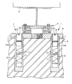
本発明の実施の形態を図により説明する。図1は、本発明の支承固定構造を用いた支承構造示す図であり、図2は、支承固定構造の一部拡大図である。本発明の支承固定構造は、橋梁、建築等の構造物の支承装置の固定構造として用いられるものであり、支承装置の種類に限定されるものではない。また、図1では、下部構造への固定のために用いた例が示されているが、コンクリート製であれば上部構造に用いてよい。 Embodiments of the present invention will be described with reference to the drawings. FIG. 1 is a view showing a support structure using the support fixing structure of the present invention, and FIG. 2 is a partially enlarged view of the support fixing structure. The bearing fixing structure of the present invention is used as a fixing structure for a bearing device for structures such as bridges and buildings, and is not limited to the type of the bearing device. Moreover, although the example used for fixation to a lower structure is shown in FIG. 1, if it is a product made from concrete, you may use for an upper structure.
図1に示される実施形態では、本発明の支承固定構造1は、上部構造2とコンクリート製の下部構造3の間に設置され支承装置4をコンクリート製の下部構造3に固定するために用いられる。支承固定構造1は、下部構造3に固定される支承取付用プレート5を備える。支承取付用プレート5に予め支承装置22が固定された状態で設置現場に搬送される。支承取付用プレート5には複数の取付穴10が形成される。
In the embodiment shown in FIG. 1, the
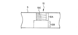
図3は、支承取付用プレート5に形成される取付穴10の縦断面図である。取付穴10は、小径部10Aと大径部10Bが段部を介して連通している。小径部10Aの内壁には上揚力対応ボルト用雌ねじ部10Cが形成される。
FIG. 3 is a longitudinal sectional view of the
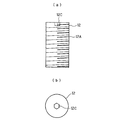
本発明の支承固定構造1は、図4(a)、(b)、(c)に示される円筒形のカプラー11を備える。円筒形のカプラー11の外径は、支承取付用プレート5に形成した取付穴10の大径部10Bの内径とほぼ同じとする。図4(a)に示されるカプラー11は、その内周に同じ内径の雌ねじが形成され、上方の雌ねじが上揚力対応ボルト用雌ねじ部11Aで下方の雌ねじがアンカーボルト用雌ねじ部11Bとする。上揚力対応ボルト用雌ねじ部11Aは、支承取付用プレート5に形成した取付穴10の小径部10Aに形成した上揚力対応ボルト用雌ねじ部10Cの内径と同じでピッチも同じとする。
The
図4(b)に示されるカプラー11は、その内周に上揚力対応ボルト用雌ねじ部11A
とアンカーボルト用雌ねじ部11Bを形成し、上揚力対応ボルト用雌ねじ部11Aの内径をアンカーボルト用雌ねじ部11Bの内径より大きくし、互いが連通するようにしたものである。上揚力対応ボルト用雌ねじ部11Aとアンカーボルト用雌ねじ部11Bの内径を異なるように形成することにより、それぞれの螺着長を正確に設定できる。上揚力対応ボルト用雌ねじ部11Aの内径をアンカーボルト用雌ねじ部11Bの内径より小さくしても良い。
The
And an anchor bolt
図4(c)に示されるカプラー11は、その内周に上揚力対応ボルト用雌ねじ部11A
とアンカーボルト用雌ねじ部11Bを形成し、上揚力対応ボルト用雌ねじ部11Aの内径をアンカーボルト用雌ねじ部11Bの内径より大きくし、互いが連通しないようにしたものである。上揚力対応ボルト用雌ねじ部11Aとアンカーボルト用雌ねじ部11Bの内径を異なるように形成することにより、それぞれの螺着長を正確に設定できる。上揚力対応ボルト用雌ねじ部11Aの内径をアンカーボルト用雌ねじ部11Bの内径より小さくしても良い。
The
And an anchor bolt
本発明の支承固定構造1は、図5(a)、(b)に示される上揚力対応ボルト12を備える。上揚力対応ボルト12は、その外周に雄ねじ部12Aが形成され、上端面に回動工具係合用凹部12Cが形成される。上揚力対応ボルト12の雄ねじ部12Bは、支承取付用プレート5に形成した取付穴10の小径部10Bの上揚力対応ボルト用雌ねじ部10C
とカプラー11に形成した上揚力対応ボルト用雌ねじ部11Aに渡って螺着される。
The
And the upper lifting force corresponding bolt
本発明の支承固定構造1は、図6に示されるアンカーボルト13を備える。アンカーボルト13の一端には、雄ねじ部13Aが形成される。アンカーボルト13の雄ねじ部13Aは、カプラー11のアンカーボルト用雌ねじ部11Bに螺着される。
The
本発明の支承固定構造1の設置の施工手順を説明する。コンクリート製の下部構造3にアンカーボルト用穴20を形成する。アンカーボルト用穴20は、支承取付用プレート5に形成した取付穴10の形成位置に対応するように形成する。支承取付用プレート5に支承装置支承装置22を設置する。支承取付用プレート5の取付穴10の大径部10Bに、アンカーボルト13の雄ねじ部13Aをアンカーボルト用雌ねじ部11Bに螺着したカプラーを配置する。回動工具係合凹部12Cに回動工具を係合させて駆動することにより、支承取付用プレート5の取付穴10の小径部10Aの上揚力対応ボルト用雌ねじ部10Cとカプラー11に形成した上揚力対応ボルト用雌ねじ部11Aに渡って、上揚力対応ボルト12の雄ねじ部12Aを螺着し、支承取付プレート5とアンカーボルト13を連結する。その際、上揚力対応ボルト12の上端面と支承取付プレート5の表面とが同一面となるようにする。そうすることにより、支承取付用プレート5の表面に邪魔な突起部が形成されないため他の支承装置の構成部材の配置が容易になる。
A construction procedure for installing the
アンカーボルト13をアンカーボルト用穴20に配置する。支承取付用プレート5のレベルを調整し、アンカーボルト用穴20に無収縮モルタル等の固化性充填材21を充填し固化させることにより、支承装置4を載置した支承取付プレート5を下部構造3に固定する。支承装置4と上部構造2を連結固定する。上揚力対応ボルト12の上端面に形成した回動工具係合用凹部12Cに除去可能で耐腐食性の充填材を充填すると水等が溜まり腐食するのを防止できる。
The
支承装置4を取り替えるための撤去作業の手順を説明する。上揚力対応ボルト12の
回動工具係合凹部12Cに回動工具を係合し、上揚力対応ボルト12を解除方向に回動させ、支承取付用プレート5の取付穴10の小径部10Aの上揚力対応ボルト用雌ねじ部10Cとカプラー11に形成した上揚力対応ボルト用雌ねじ部11Aとの螺着を解除する。支承取付用プレート5は、下部構造3との固定が解除されるため、支承装置4と上部構造2との連結を解除し、上部構造2をジャッキアップして支承装置4を載置した支承取付用プレート5を撤去する。その後、カプラー11とアンカーボルト13の螺着を解除し、カプラー11を撤去する。
The procedure of the removal work for replacing the
以上のように、本発明の支承固定構造は、地震時の水平力、上揚力に抵抗することができ、上部構造又は下部構造への支承装置の設置、撤去を容易とすることができる。 As described above, the bearing fixing structure of the present invention can resist the horizontal force and the lifting force during an earthquake, and can easily install and remove the bearing device from the upper structure or the lower structure.
1:支承固定構造、2:上部構造、3:下部構造、4:支承装置、5:支承取付用プレート、10:取付穴、10A:小径部、10B:大径部、10C:上揚力対応ボルト用雌ねじ部、11:カプラー、11A:上揚力対応ボルト用雌ねじ部、11B:アンカーボルト用雌ねじ部、12:上揚力対応ボルト、12A:雄ねじ部、12C:回動工具係合用凹部、13:アンカーボルト、13A:雄ねじ部、20:アンカーボルト用穴、21:固化性充填材 1: support fixing structure, 2: upper structure, 3: lower structure, 4: support device, 5: support mounting plate, 10: mounting hole, 10A: small diameter part, 10B: large diameter part, 10C: uplift bolt Female thread part, 11: coupler, 11A: female thread part for bolts for uplift, 11B: female thread part for anchor bolts, 12: bolts for uplifting force, 12A: male thread part, 12C: recess for engaging rotating tool, 13: anchor Bolt, 13A: male screw part, 20: hole for anchor bolt, 21: solidifying filler
Claims (3)
外周に雄ねじ部を有し上端面に回動工具係合凹部を有する上揚力対応ボルトと、
先端部に前記アンカーボルト用雌ねじ穴に螺着される雄ねじ部を形成したアンカーボルトと、
上揚力対応ボルト用雌ねじ部を有する小径部と前記小径部と段部を介して連通する前記カプラーの外径とほぼ同じ内径の大径部を有する取付穴を形成した支承取付用プレートと、
を備え、
前記アンカーボルトの先端雄ねじ部を前記カプラーのアンカーボルト用雌ねじ部に螺着した前記カプラーを前記取付穴の前記大径部に配し、前記上揚力対応ボルトを前記取付穴の小径部の上揚力対応ボルト用雌ねじ部と前記カプラーの上揚力対応ボルト用雌ねじ部に渡って螺着し固定することを特徴とする支承固定構造。 There is a female screw portion for anchor bolts at the bottom and a female screw portion for bolts corresponding to the uplift force at the bottom. A cylindrical coupler in which the internal thread hole for repulsive force is in communication or non-communication ;
An uplifting bolt having a male threaded portion on the outer periphery and a rotating tool engaging recess on the upper end surface;
An anchor bolt in which a male thread portion screwed into the anchor bolt female thread hole is formed at the tip;
A support mounting plate in which a mounting hole having a small diameter portion having a female thread portion for an uplifting bolt and a large diameter portion having substantially the same inner diameter as the outer diameter of the coupler communicating with the small diameter portion via a step portion;
With
The coupler in which the male screw portion of the tip end of the anchor bolt is screwed to the female screw portion for the anchor bolt of the coupler is arranged in the large diameter portion of the mounting hole, and the uplift force corresponding bolt is used as the upper lifting force of the small diameter portion of the mounting hole. A bearing fixing structure characterized by being screwed and fixed across the female thread portion for the corresponding bolt and the female thread portion for the upward lifting force of the coupler.
Priority Applications (1)
| Application Number | Priority Date | Filing Date | Title |
|---|---|---|---|
| JP2009060885A JP5334635B2 (en) | 2009-03-13 | 2009-03-13 | Bearing fixing structure |
Applications Claiming Priority (1)
| Application Number | Priority Date | Filing Date | Title |
|---|---|---|---|
| JP2009060885A JP5334635B2 (en) | 2009-03-13 | 2009-03-13 | Bearing fixing structure |
Publications (2)
| Publication Number | Publication Date |
|---|---|
| JP2010216085A JP2010216085A (en) | 2010-09-30 |
| JP5334635B2 true JP5334635B2 (en) | 2013-11-06 |
Family
ID=42975201
Family Applications (1)
| Application Number | Title | Priority Date | Filing Date |
|---|---|---|---|
| JP2009060885A Expired - Fee Related JP5334635B2 (en) | 2009-03-13 | 2009-03-13 | Bearing fixing structure |
Country Status (1)
| Country | Link |
|---|---|
| JP (1) | JP5334635B2 (en) |
Families Citing this family (4)
| Publication number | Priority date | Publication date | Assignee | Title |
|---|---|---|---|---|
| JP6091695B1 (en) * | 2016-12-19 | 2017-03-08 | 株式会社ビービーエム | Bridge bearing device |
| CN109356022B (en) * | 2018-10-29 | 2021-06-25 | 株洲时代新材料科技股份有限公司 | Spherical support |
| JP2020169503A (en) * | 2019-04-04 | 2020-10-15 | 株式会社ビー・ビー・エム | Bearing structure with damage control function for bridge |
| KR102209904B1 (en) * | 2020-06-09 | 2021-02-03 | (주)대림이엔씨 | Anchorsocket height controlable support device and construction method thereof |
Family Cites Families (5)
| Publication number | Priority date | Publication date | Assignee | Title |
|---|---|---|---|---|
| JPS59101006U (en) * | 1982-12-27 | 1984-07-07 | 有限会社山川製材工務 | joint mechanism |
| JPH0342088Y2 (en) * | 1985-05-29 | 1991-09-04 | ||
| JP2002069929A (en) * | 2000-08-30 | 2002-03-08 | Haltec:Kk | Connection structure of cable on pc bridge |
| JP2006207119A (en) * | 2005-01-25 | 2006-08-10 | Kawaguchi Metal Industries Co Ltd | Functional maintenance method of bridge bearing in case of earthquake, bolt for fixing the bridge bearing to lower structure and fixed construction of the bridge bearing and the lower structure |
| JP2008002062A (en) * | 2006-06-20 | 2008-01-10 | Kaimon:Kk | Fixing structure for lower and upper shoes of support for bridge |
-
2009
- 2009-03-13 JP JP2009060885A patent/JP5334635B2/en not_active Expired - Fee Related
Also Published As
| Publication number | Publication date |
|---|---|
| JP2010216085A (en) | 2010-09-30 |
Similar Documents
| Publication | Publication Date | Title |
|---|---|---|
| JP4702862B1 (en) | Height adjustment support device for structure and height adjustment method for structure support device | |
| JP4726093B1 (en) | Support device for height adjustment for structures | |
| JP5334635B2 (en) | Bearing fixing structure | |
| CN105421222A (en) | Socket and spigot joint type connection structure for bridge prefabricated pier stand column and bearing platform and splicing method of socket and spigot joint type connection structure | |
| CN106049760A (en) | Prefabricated concrete column base used for rapid restoration after earthquakes, and construction method and maintenance method thereof | |
| KR101019588B1 (en) | Buoyancy prevention device for hollow slab | |
| JP2010216086A (en) | Coupler for fixing bearing device | |
| CN108797381B (en) | A method of removing and replacing a boom | |
| CN214461240U (en) | Bracket positioning and mounting system | |
| JP5430628B2 (en) | Foundation pile construction method, foundation pile and solar cell array | |
| JP7018253B2 (en) | Column base hardware and how to build a column base structure using it | |
| JP2006207119A (en) | Functional maintenance method of bridge bearing in case of earthquake, bolt for fixing the bridge bearing to lower structure and fixed construction of the bridge bearing and the lower structure | |
| JP2011021711A (en) | Steel sheet fastener and steel sheet joining method | |
| KR20160059533A (en) | Vertical degree control apparatus | |
| JP2025075704A (en) | Fastening mechanism | |
| ES2811826T3 (en) | Anchor plug | |
| CN115807508A (en) | Construction method and node for building steel structure column base installation foundation | |
| JP2018204419A (en) | Bearing replacement method for existing concrete girders | |
| JP4797050B2 (en) | Concrete product with height adjustment mechanism | |
| JP6647778B2 (en) | Post-installed anchor and its installation method | |
| JP2013002193A (en) | Tie bolt for suspending floor board-receiving beam in concrete construction of bridge girder, and installation method of tie bolt for suspending floor board-receiving beam in concrete construction of bridge girder | |
| JP2006112171A (en) | Diagonal anchoring nut mounting jig for diagonal tensioning bridge, and diagonal anchoring nut setting method | |
| CN117005556B (en) | Construction method and structure for mechanical reinforcement of steel column foot anchor bolt | |
| CN111287901A (en) | Lower tower section of concrete tower and concrete tower having the same | |
| KR101634554B1 (en) | Insulating buried screw and installation method of frame using the same |
Legal Events
| Date | Code | Title | Description |
|---|---|---|---|
| A621 | Written request for application examination |
Free format text: JAPANESE INTERMEDIATE CODE: A621 Effective date: 20120110 |
|
| A977 | Report on retrieval |
Free format text: JAPANESE INTERMEDIATE CODE: A971007 Effective date: 20121206 |
|
| A131 | Notification of reasons for refusal |
Free format text: JAPANESE INTERMEDIATE CODE: A131 Effective date: 20121212 |
|
| A521 | Written amendment |
Free format text: JAPANESE INTERMEDIATE CODE: A523 Effective date: 20130130 |
|
| TRDD | Decision of grant or rejection written | ||
| A01 | Written decision to grant a patent or to grant a registration (utility model) |
Free format text: JAPANESE INTERMEDIATE CODE: A01 Effective date: 20130717 |
|
| A61 | First payment of annual fees (during grant procedure) |
Free format text: JAPANESE INTERMEDIATE CODE: A61 Effective date: 20130730 |
|
| R150 | Certificate of patent or registration of utility model |
Ref document number: 5334635 Country of ref document: JP Free format text: JAPANESE INTERMEDIATE CODE: R150 Free format text: JAPANESE INTERMEDIATE CODE: R150 |
|
| R250 | Receipt of annual fees |
Free format text: JAPANESE INTERMEDIATE CODE: R250 |
|
| R250 | Receipt of annual fees |
Free format text: JAPANESE INTERMEDIATE CODE: R250 |
|
| R250 | Receipt of annual fees |
Free format text: JAPANESE INTERMEDIATE CODE: R250 |
|
| R250 | Receipt of annual fees |
Free format text: JAPANESE INTERMEDIATE CODE: R250 |
|
| LAPS | Cancellation because of no payment of annual fees |