JP5334272B2 - Gas quantification generator for volatile organic compounds - Google Patents
Gas quantification generator for volatile organic compounds Download PDFInfo
- Publication number
- JP5334272B2 JP5334272B2 JP2011177102A JP2011177102A JP5334272B2 JP 5334272 B2 JP5334272 B2 JP 5334272B2 JP 2011177102 A JP2011177102 A JP 2011177102A JP 2011177102 A JP2011177102 A JP 2011177102A JP 5334272 B2 JP5334272 B2 JP 5334272B2
- Authority
- JP
- Japan
- Prior art keywords
- gas
- container
- diffusion
- voc
- filter
- Prior art date
- Legal status (The legal status is an assumption and is not a legal conclusion. Google has not performed a legal analysis and makes no representation as to the accuracy of the status listed.)
- Active
Links
- 239000012855 volatile organic compound Substances 0.000 title claims description 101
- 238000011002 quantification Methods 0.000 title claims 3
- 238000009792 diffusion process Methods 0.000 claims description 91
- 239000002245 particle Substances 0.000 claims description 21
- 229920000642 polymer Polymers 0.000 claims description 18
- 239000011148 porous material Substances 0.000 claims description 9
- 230000006698 induction Effects 0.000 claims description 6
- 238000005245 sintering Methods 0.000 claims description 6
- 239000007789 gas Substances 0.000 description 105
- 238000005259 measurement Methods 0.000 description 15
- ZQBFAOFFOQMSGJ-UHFFFAOYSA-N hexafluorobenzene Chemical compound FC1=C(F)C(F)=C(F)C(F)=C1F ZQBFAOFFOQMSGJ-UHFFFAOYSA-N 0.000 description 12
- 238000002347 injection Methods 0.000 description 10
- 239000007924 injection Substances 0.000 description 10
- -1 trichloroethylene, tetrachloroethylene, chlorodibromomethane Chemical class 0.000 description 10
- 239000007788 liquid Substances 0.000 description 6
- 239000000463 material Substances 0.000 description 6
- 239000004743 Polypropylene Substances 0.000 description 4
- 239000004809 Teflon Substances 0.000 description 4
- 229920006362 Teflon® Polymers 0.000 description 4
- 229920001155 polypropylene Polymers 0.000 description 4
- 229920001296 polysiloxane Polymers 0.000 description 4
- 238000007789 sealing Methods 0.000 description 4
- 238000009736 wetting Methods 0.000 description 4
- ZWEHNKRNPOVVGH-UHFFFAOYSA-N 2-Butanone Chemical compound CCC(C)=O ZWEHNKRNPOVVGH-UHFFFAOYSA-N 0.000 description 3
- UHOVQNZJYSORNB-UHFFFAOYSA-N Benzene Chemical compound C1=CC=CC=C1 UHOVQNZJYSORNB-UHFFFAOYSA-N 0.000 description 3
- XEKOWRVHYACXOJ-UHFFFAOYSA-N Ethyl acetate Chemical compound CCOC(C)=O XEKOWRVHYACXOJ-UHFFFAOYSA-N 0.000 description 3
- 239000004698 Polyethylene Substances 0.000 description 3
- YXFVVABEGXRONW-UHFFFAOYSA-N Toluene Chemical compound CC1=CC=CC=C1 YXFVVABEGXRONW-UHFFFAOYSA-N 0.000 description 3
- 229920005549 butyl rubber Polymers 0.000 description 3
- 230000000052 comparative effect Effects 0.000 description 3
- 239000011521 glass Substances 0.000 description 3
- 238000004519 manufacturing process Methods 0.000 description 3
- 239000012528 membrane Substances 0.000 description 3
- 238000000465 moulding Methods 0.000 description 3
- VLKZOEOYAKHREP-UHFFFAOYSA-N n-Hexane Chemical compound CCCCCC VLKZOEOYAKHREP-UHFFFAOYSA-N 0.000 description 3
- 229920000573 polyethylene Polymers 0.000 description 3
- 229920006268 silicone film Polymers 0.000 description 3
- 230000004580 weight loss Effects 0.000 description 3
- FYGHSUNMUKGBRK-UHFFFAOYSA-N 1,2,3-trimethylbenzene Chemical compound CC1=CC=CC(C)=C1C FYGHSUNMUKGBRK-UHFFFAOYSA-N 0.000 description 2
- BZHMBWZPUJHVEE-UHFFFAOYSA-N 2,4-dimethylpentane Chemical compound CC(C)CC(C)C BZHMBWZPUJHVEE-UHFFFAOYSA-N 0.000 description 2
- IJGRMHOSHXDMSA-UHFFFAOYSA-N Atomic nitrogen Chemical compound N#N IJGRMHOSHXDMSA-UHFFFAOYSA-N 0.000 description 2
- HEDRZPFGACZZDS-UHFFFAOYSA-N Chloroform Chemical compound ClC(Cl)Cl HEDRZPFGACZZDS-UHFFFAOYSA-N 0.000 description 2
- YNQLUTRBYVCPMQ-UHFFFAOYSA-N Ethylbenzene Chemical compound CCC1=CC=CC=C1 YNQLUTRBYVCPMQ-UHFFFAOYSA-N 0.000 description 2
- LRHPLDYGYMQRHN-UHFFFAOYSA-N N-Butanol Chemical compound CCCCO LRHPLDYGYMQRHN-UHFFFAOYSA-N 0.000 description 2
- IMNFDUFMRHMDMM-UHFFFAOYSA-N N-Heptane Chemical compound CCCCCCC IMNFDUFMRHMDMM-UHFFFAOYSA-N 0.000 description 2
- PPBRXRYQALVLMV-UHFFFAOYSA-N Styrene Chemical compound C=CC1=CC=CC=C1 PPBRXRYQALVLMV-UHFFFAOYSA-N 0.000 description 2
- DIOQZVSQGTUSAI-UHFFFAOYSA-N decane Chemical compound CCCCCCCCCC DIOQZVSQGTUSAI-UHFFFAOYSA-N 0.000 description 2
- 238000010438 heat treatment Methods 0.000 description 2
- 238000009434 installation Methods 0.000 description 2
- XMGQYMWWDOXHJM-UHFFFAOYSA-N limonene Chemical compound CC(=C)C1CCC(C)=CC1 XMGQYMWWDOXHJM-UHFFFAOYSA-N 0.000 description 2
- BKIMMITUMNQMOS-UHFFFAOYSA-N nonane Chemical compound CCCCCCCCC BKIMMITUMNQMOS-UHFFFAOYSA-N 0.000 description 2
- 230000000149 penetrating effect Effects 0.000 description 2
- 239000011347 resin Substances 0.000 description 2
- 229920005989 resin Polymers 0.000 description 2
- 239000000126 substance Substances 0.000 description 2
- VZGDMQKNWNREIO-UHFFFAOYSA-N tetrachloromethane Chemical compound ClC(Cl)(Cl)Cl VZGDMQKNWNREIO-UHFFFAOYSA-N 0.000 description 2
- RSJKGSCJYJTIGS-UHFFFAOYSA-N undecane Chemical compound CCCCCCCCCCC RSJKGSCJYJTIGS-UHFFFAOYSA-N 0.000 description 2
- WGECXQBGLLYSFP-UHFFFAOYSA-N (+-)-2,3-dimethyl-pentane Natural products CCC(C)C(C)C WGECXQBGLLYSFP-UHFFFAOYSA-N 0.000 description 1
- UOCLXMDMGBRAIB-UHFFFAOYSA-N 1,1,1-trichloroethane Chemical compound CC(Cl)(Cl)Cl UOCLXMDMGBRAIB-UHFFFAOYSA-N 0.000 description 1
- QIROQPWSJUXOJC-UHFFFAOYSA-N 1,1,2,2,3,3,4,4,5,5,6-undecafluoro-6-(trifluoromethyl)cyclohexane Chemical compound FC(F)(F)C1(F)C(F)(F)C(F)(F)C(F)(F)C(F)(F)C1(F)F QIROQPWSJUXOJC-UHFFFAOYSA-N 0.000 description 1
- SCYULBFZEHDVBN-UHFFFAOYSA-N 1,1-Dichloroethane Chemical compound CC(Cl)Cl SCYULBFZEHDVBN-UHFFFAOYSA-N 0.000 description 1
- USPWUOFNOTUBAD-UHFFFAOYSA-N 1,2,3,4,5-pentafluoro-6-(trifluoromethyl)benzene Chemical compound FC1=C(F)C(F)=C(C(F)(F)F)C(F)=C1F USPWUOFNOTUBAD-UHFFFAOYSA-N 0.000 description 1
- KNKRKFALVUDBJE-UHFFFAOYSA-N 1,2-dichloropropane Chemical compound CC(Cl)CCl KNKRKFALVUDBJE-UHFFFAOYSA-N 0.000 description 1
- OCJBOOLMMGQPQU-UHFFFAOYSA-N 1,4-dichlorobenzene Chemical compound ClC1=CC=C(Cl)C=C1 OCJBOOLMMGQPQU-UHFFFAOYSA-N 0.000 description 1
- DKPFZGUDAPQIHT-UHFFFAOYSA-N Butyl acetate Natural products CCCCOC(C)=O DKPFZGUDAPQIHT-UHFFFAOYSA-N 0.000 description 1
- YCKRFDGAMUMZLT-UHFFFAOYSA-N Fluorine atom Chemical compound [F] YCKRFDGAMUMZLT-UHFFFAOYSA-N 0.000 description 1
- NTIZESTWPVYFNL-UHFFFAOYSA-N Methyl isobutyl ketone Chemical compound CC(C)CC(C)=O NTIZESTWPVYFNL-UHFFFAOYSA-N 0.000 description 1
- UIHCLUNTQKBZGK-UHFFFAOYSA-N Methyl isobutyl ketone Natural products CCC(C)C(C)=O UIHCLUNTQKBZGK-UHFFFAOYSA-N 0.000 description 1
- CTQNGGLPUBDAKN-UHFFFAOYSA-N O-Xylene Chemical compound CC1=CC=CC=C1C CTQNGGLPUBDAKN-UHFFFAOYSA-N 0.000 description 1
- 239000004793 Polystyrene Substances 0.000 description 1
- VYPSYNLAJGMNEJ-UHFFFAOYSA-N Silicium dioxide Chemical compound O=[Si]=O VYPSYNLAJGMNEJ-UHFFFAOYSA-N 0.000 description 1
- 150000007824 aliphatic compounds Chemical class 0.000 description 1
- XAGFODPZIPBFFR-UHFFFAOYSA-N aluminium Chemical compound [Al] XAGFODPZIPBFFR-UHFFFAOYSA-N 0.000 description 1
- 229910052782 aluminium Inorganic materials 0.000 description 1
- 150000001491 aromatic compounds Chemical class 0.000 description 1
- 238000009835 boiling Methods 0.000 description 1
- 150000001875 compounds Chemical class 0.000 description 1
- 238000001816 cooling Methods 0.000 description 1
- 230000007423 decrease Effects 0.000 description 1
- 238000010790 dilution Methods 0.000 description 1
- 239000012895 dilution Substances 0.000 description 1
- 230000007613 environmental effect Effects 0.000 description 1
- 229910052731 fluorine Inorganic materials 0.000 description 1
- 239000011737 fluorine Substances 0.000 description 1
- FUZZWVXGSFPDMH-UHFFFAOYSA-M hexanoate Chemical compound CCCCCC([O-])=O FUZZWVXGSFPDMH-UHFFFAOYSA-M 0.000 description 1
- 229940087305 limonene Drugs 0.000 description 1
- 235000001510 limonene Nutrition 0.000 description 1
- 238000000034 method Methods 0.000 description 1
- 229910052757 nitrogen Inorganic materials 0.000 description 1
- TVMXDCGIABBOFY-UHFFFAOYSA-N octane Chemical compound CCCCCCCC TVMXDCGIABBOFY-UHFFFAOYSA-N 0.000 description 1
- 150000004045 organic chlorine compounds Chemical class 0.000 description 1
- 239000003960 organic solvent Substances 0.000 description 1
- LOQGSOTUHASIHI-UHFFFAOYSA-N perfluoro-1,3-dimethylcyclohexane Chemical compound FC(F)(F)C1(F)C(F)(F)C(F)(F)C(F)(F)C(F)(C(F)(F)F)C1(F)F LOQGSOTUHASIHI-UHFFFAOYSA-N 0.000 description 1
- 239000012466 permeate Substances 0.000 description 1
- 229920001084 poly(chloroprene) Polymers 0.000 description 1
- 229920000728 polyester Polymers 0.000 description 1
- 229920002223 polystyrene Polymers 0.000 description 1
- 239000000047 product Substances 0.000 description 1
- 239000003566 sealing material Substances 0.000 description 1
- 238000007493 shaping process Methods 0.000 description 1
- 239000000741 silica gel Substances 0.000 description 1
- 229910002027 silica gel Inorganic materials 0.000 description 1
- 229920002379 silicone rubber Polymers 0.000 description 1
- 239000007787 solid Substances 0.000 description 1
- 239000000243 solution Substances 0.000 description 1
- 229910001220 stainless steel Inorganic materials 0.000 description 1
- 239000010935 stainless steel Substances 0.000 description 1
- 239000010409 thin film Substances 0.000 description 1
- 239000008096 xylene Substances 0.000 description 1
Images


Description
本発明は、揮発性有機化合物(VOC)からガスを発生させるための加熱装置およびポンプなどの動力源なしに、VOCガスを定量的に発生させる装置に関する。より詳細には、容器に収容したVOCを特定のフィルタを通して分子拡散させることによって、VOCガスを定量的に発生させる装置に関する。 The present invention relates to a heating apparatus for generating gas from volatile organic compounds (VOC) and an apparatus for quantitatively generating VOC gas without a power source such as a pump. More specifically, the present invention relates to an apparatus for quantitatively generating VOC gas by molecularly diffusing VOC contained in a container through a specific filter.
VOCガスを定量的に発生させる装置の代表例として、インピンジャーと、エアーポンプと、シリカゲル管と、流量計とを備えた装置が挙げられる(非特許文献1を参照)。このような装置では、インピンジャー内にVOC溶液を注入し、その液面上に空気を一定の流量で流すことによって、VOCガスを外部に拡散させている。しかし、このような装置は、(1)VOCからガスを発生させるためにエアーポンプ等の動力源が必要である、(2)配管が長く結露しやすい、(3)発生するガスの濃度がばらつきやすい、(4)発生するガスを低濃度に制御することが困難であるなどの点で改善が望まれている。 A representative example of a device that generates VOC gas quantitatively includes a device that includes an impinger, an air pump, a silica gel tube, and a flow meter (see Non-Patent Document 1). In such an apparatus, a VOC solution is injected into an impinger and air is allowed to flow over the liquid surface to diffuse VOC gas to the outside. However, such a device requires (1) a power source such as an air pump to generate gas from the VOC, (2) the piping is long and easy to condense , (3) the concentration of the generated gas varies. Improvement is desired in that it is easy and (4) it is difficult to control the generated gas to a low concentration.
VOCガスを定量的に発生させる装置の別の例として、パーミエーションチューブまたはディフュージョンチューブにVOCを導入し、VOCを分子拡散させることによって、動力源なしにガスを発生させる装置が挙げられる(非特許文献2)。パーミエーションチューブを用いた装置の具体例として、フッ素樹脂管にVOC(液化ガス)を封入し、管壁を通って一定量の液化ガスが浸透拡散するように管を恒温に保持することによって、微量濃度の標準ガスを連続的に発生させる装置が挙げられる。しかし、このようなパーミエーションチューブは、装置の大部分を構成することになるため、(1)ガスの発生量が多くなりすぎ、一定濃度のガスを発生させるためには空気や窒素などの希釈ガスを定量的に供給する必要がある、(2)測定時にチューブが汚染されやすく、測定誤差が生じ易いなどの点で改善が望まれている。一方、ディフュージョンチューブを用いた装置の具体例として、ガラス製液体溜め容器の上部に円柱状の拡散塔を設け、容器内に導入したVOCを拡散塔の上部から蒸発拡散させる装置が挙げられる。しかし、このような装置は、拡散塔の上部が開口しているため、風などの外部環境の影響を受けやすく、ガスの発生量がバラツキ易い点で改善が望まれている。 Another example of a device that quantitatively generates VOC gas is a device that generates gas without a power source by introducing VOC into a permeation tube or a diffusion tube and allowing VOC to molecularly diffuse (non-patent document). Reference 2). As a specific example of a device using a permeation tube, by enclosing VOC (liquefied gas) in a fluororesin tube and holding the tube at a constant temperature so that a certain amount of liquefied gas permeates and diffuses through the tube wall, An apparatus that continuously generates a small amount of standard gas can be used. However, since such a permeation tube constitutes a large part of the apparatus, (1) the amount of generated gas is excessive, and in order to generate a constant concentration of gas, dilution of air, nitrogen, etc. Improvement is desired in that it is necessary to supply gas quantitatively, (2) the tube is easily contaminated during measurement, and measurement errors are likely to occur. On the other hand, as a specific example of an apparatus using a diffusion tube, there is an apparatus in which a cylindrical diffusion tower is provided in the upper part of a glass liquid storage container, and VOC introduced into the container is evaporated and diffused from the upper part of the diffusion tower. However, such an apparatus is desired to be improved in that the upper part of the diffusion tower is open, so that it is easily affected by the external environment such as wind, and the amount of generated gas is likely to vary.
VOCガスを定量的に発生させる装置のさらに別の例として、スクリュー管などのVOCを収容する容器にシリコーン膜を被せ、さらに穴開きキャップで封止した構造を有する装置が挙げられる(非特許文献3)。しかし、このような装置は、(1)容器の密閉性が悪くキャップの隙間からVOCの液体やガスが漏れやすく、発生速度にバラツキが生じやすい、(2)シリコーン膜では透過量が多くなるため、ガスの発生量が多くなりやすい、(3)スクリュー管およびシリコーン膜の固体差が大きいため、発生装置間の性能にバラツキが生じやすい、(4)装置の輸送時などにVOCでシリコーン膜が濡れやすく、またシリコーン膜が濡れるとガスの発生速度にバラツキが生じやすくなる、などの点で改善が望まれている。(4)に関しては、輸送時の拡散フィルタの濡れを防止するために、設置場所でVOCをスクリュー管に導入する場合もあるが、設置場所でVOCを撒き散らす可能性があること、そのことによって作業者がVOCに触れ、また測定時に誤差を生じるなどの点でさらなる改善が望まれている。 Yet another example of a device that quantitatively generates VOC gas is a device having a structure in which a VOC containing container such as a screw tube is covered with a silicone film and sealed with a perforated cap (Non-Patent Document). 3). However, in such a device, (1) VOC liquid or gas is likely to leak from the gap of the cap due to poor sealing performance of the container, and the generation rate is likely to vary. (2) The amount of permeation increases in the silicone membrane. The amount of gas generated is likely to increase. (3) Because the solid difference between the screw tube and the silicone membrane is large, the performance between the generators tends to vary. (4) The silicone membrane is formed by VOC during transportation of the device. Improvements are desired in that they are easily wetted, and when the silicone film gets wet, the gas generation rate tends to vary. Regarding (4), in order to prevent wetting of the diffusion filter during transportation, VOC may be introduced into the screw pipe at the installation location, but there is a possibility that VOC may be scattered at the installation location. Further improvement is desired in that the operator touches the VOC and an error occurs during measurement.
上述のように、VOCガスを定量的に発生させる装置に関するいくつかの報告があるが、いずれについてもさらなる改善が望まれているのが現状である。したがって、本発明は、微量なVOCガスを定量的に発生させることが可能であり、また輸送時などのVOCの漏れおよびVOCによる拡散フィルタの濡れを容易に防止することが可能であり、さらに測定場所での装置設置が容易である、簡便かつ高性能のVOCガス定量発生装置を提供することを課題とする。 As described above, there have been several reports on devices that quantitatively generate VOC gas, but the current situation is that further improvements are desired for all of them. Therefore, the present invention can quantitatively generate a small amount of VOC gas, and can easily prevent leakage of VOC during transportation and wetting of the diffusion filter due to VOC , and further measurement. It is an object of the present invention to provide a simple and high-performance VOC gas quantitative generation device that is easy to install at a place.
本発明者らは、分子拡散によってVOCガスを定量的に発生させる装置について鋭意検討を行い、容器に収容したVOCを特定の拡散フィルタを介し分子拡散させることによってVOCガスの微量な拡散を精度良く制御することが可能であることを見出し、本発明を完成するに至った。すなわち、本発明は以下に関する。 The inventors of the present invention have intensively studied a device that quantitatively generates VOC gas by molecular diffusion, and accurately diffuses a small amount of VOC gas by molecularly diffusing VOC contained in a container through a specific diffusion filter. The inventors have found that it is possible to control, and have completed the present invention. That is, the present invention relates to the following.
本発明による揮発性有機化合物のガス定量発生装置の第1の態様は、揮発性有機化合物を収容する容器と、上記容器の開口部を覆い、かつ上記揮発性有機化合物から発生するガスを上記容器の外部に拡散させる拡散口を有するキャップと、上記キャップの拡散口を覆い、かつ上記ガスの拡散を制御する拡散フィルタとを備え、上記拡散フィルタがポリマー粒子を焼結して得られる焼結フィルタであることを特徴とする。ここで、焼結フィルタの孔径は、5〜300μmの範囲であることが好ましい。 A first aspect of a volatile organic compound gas quantitative generation apparatus according to the present invention is a container that contains a volatile organic compound, and covers the opening of the container and generates a gas generated from the volatile organic compound in the container. A sintered filter obtained by sintering the polymer particles, the cap having a diffusion port for diffusing outside, and a diffusion filter for covering the diffusion port of the cap and controlling the diffusion of the gas It is characterized by being. Here, the pore diameter of the sintered filter is preferably in the range of 5 to 300 μm.
本発明による揮発性有機化合物のガス定量発生装置の第2の態様は、揮発性有機化合物を収容する第1の容器と、上記第1の容器の開口部を覆うキャップと、上記キャップを貫通し、上記揮発性有機化合物から発生するガスを上記第1の容器の外部に誘導する誘導管と、上記誘導管によって誘導された上記ガスの拡散を制御する拡散フィルタを有する拡散塔とを備え、上記拡散フィルタがポリマー粒子を焼結して得られる焼結フィルタであることを特徴とする。ここで、上記焼結フィルタの孔径は、5〜300μmの範囲であることが好ましい。
また、本発明によるガス定量発生装置では、上記第1の容器全体を収容する第2の容器をさらに有し、上記誘導管が上記第2の容器の開口部を覆う第2のキャップを貫通し、上記ガスを第2の容器の外部に誘導することが好ましい。上記ガスの拡散速度は、20℃において0.01〜0.50mg/時であることが好ましい。
A second aspect of the volatile organic compound gas quantitative generation device according to the present invention includes a first container that contains a volatile organic compound, a cap that covers the opening of the first container, and a through hole that penetrates the cap. An induction tube for guiding the gas generated from the volatile organic compound to the outside of the first container; and a diffusion tower having a diffusion filter for controlling diffusion of the gas induced by the induction tube, The diffusion filter is a sintered filter obtained by sintering polymer particles. Here, the pore diameter of the sintered filter is preferably in the range of 5 to 300 μm.
Moreover, in the gas fixed-quantity generator according to the present invention, the gas quantitative generator further includes a second container that accommodates the entire first container, and the guide tube passes through a second cap that covers the opening of the second container. Preferably, the gas is guided to the outside of the second container. The gas diffusion rate is preferably 0.01 to 0.50 mg / hour at 20 ° C.
本発明によるガス定量発生装置は、ポンプなどの駆動部を備える装置と比較して極めて簡便であり、測定場所での設置が容易であるとともに、VOCガスの微量な拡散を精度良く制御することが可能である。さらに、本発明によるVOCガス定量発生装置によれば、装置運搬時のVOCの漏れ、VOCによる拡散フィルタの濡れといった問題を確実に防止することが可能である。 The gas fixed-quantity generation device according to the present invention is extremely simple as compared with a device having a drive unit such as a pump, can be easily installed at a measurement place, and can accurately control a minute amount of VOC gas diffusion. Is possible. Furthermore, according to the VOC gas quantitative generator according to the present invention, it is possible to reliably prevent problems such as leakage of VOC during transportation of the device and wetting of the diffusion filter due to VOC.
以下、本発明によるガス定量発生装置について図面を用いて詳細に説明する。但し、図に示すガス定量発生装置は本発明の一実施形態を例示するものにすぎず、それらによって本発明を限定することを意図したものではない。
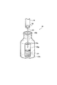
図1は、本発明によるVOCガス定量発生装置の構造を例示する模式図である。図1に示すように、ガス定量発生装置10は、揮発性有機化合物(VOC)20を収容する容器30と、容器30の開口部を覆い、かつVOCから発生するガスを容器30の外部に拡散させる拡散口(不図示)を有するキャップ40と、キャップ40の拡散口を覆い、かつガスの拡散を制御する拡散フィルタ50とを備え、拡散フィルタ50がポリマー粒子を焼結して得られる焼結フィルタであることを特徴とする。
Hereinafter, the gas fixed quantity generator according to the present invention will be described in detail with reference to the drawings. However, the gas fixed-quantity generation device shown in the figure is only an example of the present invention, and is not intended to limit the present invention.
FIG. 1 is a schematic view illustrating the structure of a VOC gas quantitative generator according to the present invention. As shown in FIG. 1, the gas
なお、本発明によるガス定量発生装置に適用可能な揮発性有機化合物(VOC)は、常温での蒸気圧が高く、常圧での沸点が低い、一般な有機溶剤であってよく、特に限定されるものではない。具体的には、ヘキサン、2,4−ジメチルペンタン、ヘプタン、オクタン、ノナン、デカン、およびウンデカン等の脂肪族系化合物が挙げられる。また、ベンゼン、トルエン、エチルベンゼン、キシレン、スチレン、およびトリメチルベンゼン等の芳香族系化合物が挙げられる。また、クロロホルム、ジクロロエタン、トリクロロエタン、四塩化炭素、ジクロロプロパン、トリクロロエチレン、テトラクロロエチレン、クロロジブロモメタン、およびパラジクロロベンゼン等の有機塩素系化合物が挙げられる。さらに、その他の化合物として、パーフルオロジメチルシクロヘキサン、パーフルオロメチルシクロヘキサン、ヘキサフルオロベンゼン、オクタフルオロトルエン、パーフルオロアリルベンゼン、酢酸エチル、酢酸ブチル、メチルエチルケトン、メチルイソブチルケトン、ブタノール、ピネン、およびリモネン等が挙げられる。 The volatile organic compound (VOC) applicable to the gas quantitative generator according to the present invention may be a general organic solvent having a high vapor pressure at normal temperature and a low boiling point at normal pressure, and is not particularly limited. It is not something. Specifically, hexane, 2,4-dimethyl pentane, heptane, octane, nonane, decane, and aliphatic compounds such as undecane. Moreover, aromatic compounds, such as benzene, toluene, ethylbenzene, xylene, styrene, and trimethylbenzene, are mentioned. Further, organic chlorine compounds such as chloroform, dichloroethane, trichloroethane, carbon tetrachloride, dichloropropane, trichloroethylene, tetrachloroethylene, chlorodibromomethane, and paradichlorobenzene can be given. Furthermore, as other compounds, like perfluoro dimethylcyclohexane, perfluoro methyl cyclohexane, hexafluorobenzene, octafluorotoluene, perfluoro lower Rirubenzen, ethyl acetate, butyl acetate, methyl ethyl ketone, methyl isobutyl ketone, butanol, pinene, and limonene etc. It is done.
本発明による装置に適用可能な容器30の形状は、少なくとも1つの開口部を有し、VOCを収容することが可能であれば如何なる形状を有してもよく、特に限定されるものではない。しかし、取り扱い性の観点から、バイアル瓶などの瓶の形状を有するものが好ましい。また、容器30は、VOCに耐性を有するとともに容器自体からVOCを発生しない材料から形成されることが好ましい。そのような材料の例として、ガラス、テフロン(登録商標)、およびステンレスが挙げられる。
Shape
容器の開口部を覆うキャップ40の形状は、VOCガスを容器の外部に拡散させる少なくとも1つの拡散口を有し、かつ開口部の形状に対応する外形を有していればよく、特に限定されるものではない。キャップ40は、例えば、図1に示したように容器の開口部に嵌め込み可能な形状としても、開口部上面に覆い被せる形状としてもよい。但し、キャップは、VOCおよびVOCガスが漏れないように密閉性に優れた材料から形成されることが好ましく、そのような材料として、テフロン(登録商標)、テフロン(登録商標)/シリコーン、ネオプレンゴム、およびブチルゴムが挙げられる。また、容器の開口部とキャップとの密閉性を高めるために、必要に応じてアルミテープなどのシール材を適用してもよい。
The shape of the
キャップに設けられる拡散口は、特に限定されるものではないが、直径で0.3mm〜50mm程度とすることが好ましく、2mm〜20mm程度とすることがより好ましい。拡散口の大きさが0.3mm以下となると、拡散フィルタの取り付けが困難となる傾向がある。一方、拡散口の大きさが50mmを超えると、拡散フィルタによってVOCガスの発生量を制御することが困難となる傾向がある。 The diffusion port provided in the cap is not particularly limited, but the diameter is preferably about 0.3 mm to 50 mm, and more preferably about 2 mm to 20 mm. When the size of the diffusion port is 0.3 mm or less, it tends to be difficult to attach the diffusion filter. On the other hand, if the size of the diffusion port exceeds 50 mm, it tends to be difficult to control the amount of VOC gas generated by the diffusion filter.
拡散フィルタ50の形状は、キャップ40に設けられた拡散口の形状に対応する外形を有していればよく、特に限定されるものではない。拡散フィルタは、例えば図1に示したようにキャップの拡散口に嵌め込み可能な形状としても、拡散口上面に覆い被せる形状としてもよい。但し、本発明で使用する拡散フィルタは、ポリマー粒子を焼結して得られるフィルタ(以下、「ポリマー粒子焼結フィルタ」と称す)でなければならない。例えば、シリコーン又はテフロン(登録商標)を延伸成型した薄膜を拡散フィルタとして適用した場合、それらフィルタにおける孔径のバラツキが大きいため、微量のVOCガスを定量的に発生することが困難である。
The shape of the
本発明で使用するポリマー粒子焼結フィルタは、当技術分野で周知の方法に従い、ポリマー粒子を金型に均一に充填した後に加熱しながら成型し、次いで冷却することによって容易に製造することが可能である。ポリマー粒子焼結フィルタの製造方法については、例えば特開2001−171205号公報、および特開2001−004609号公報を参照することが可能である。ポリマー粒子焼結フィルタの具体例として、ポリエチレン、ポリプロピレン、ポリスチレン、ポリエステル、フッ素樹脂等の樹脂からなる1〜500μm粒子を焼結して成型したものが挙げられる。なかでも、フィルタの成型が容易であるという点で、ポリエチレンまたはポリプロピレンの粒子を用いて製造したフィルタが好ましい。このようなポリマー粒子焼結フィルタは孔径が均一となるため、それらを拡散フィルタとして使用することによって、VOCから発生するガスの拡散を精度よく制御することが可能である。 Polymer particle sintered filter used in the present invention, according to methods well known in the art, the polymer particles and molded under heating after uniformly filled in a mold, and then can be easily manufactured by cooling It is. Regarding the method for producing the polymer particle sintered filter, it is possible to refer to, for example, JP 2001-171205 A and JP 2001-004609 A. Specific examples of the polymer particle sintered filter, polyethylene, polypropylene, polystyrene, polyester, and the like obtained by molding 1~500μm particles made of a resin such as a fluorine resin is sintered. Especially, the filter manufactured using the particle | grains of polyethylene or a polypropylene is preferable at the point that the shaping | molding of a filter is easy. Such polymer particles sintered filter since pore size is uniform, by using them as a diffusion filter, it is possible to accurately control the diffusion of the gas generated from the VOC.
ポリマー粒子焼結フィルタは、キャップの拡散口の大きさ、およびVOCの拡散性を考慮して成型することが好ましい。より具体的には、直径で0.3mm〜50mm程度とすることが好ましく、2mm〜20mm程度とすることがより好ましい。フィルタの大きさが0.3mm以下となると、拡散口への取り付けが困難となる傾向がある。一方、フィルタの大きさが50mmを超えると、VOCガスの発生量を制御することが困難となる傾向がある。 Polymer particle sintered filter, size of the diffusion port of the cap, and it is preferable to mold in consideration of the diffusion of VOC. More specifically, the diameter is preferably about 0.3 mm to 50 mm, more preferably about 2 mm to 20 mm. When the size of the filter is 0.3 mm or less, the attachment to the diffusion port tends to be difficult. On the other hand, if the size of the filter exceeds 50 mm, it tends to be difficult to control the amount of VOC gas generated.
ポリマー粒子焼結フィルタの厚さは、0.5mm〜10mm程度とすることが好ましい。フィルタの厚さが0.5mmよりも薄くなると、測定時に風などの外部環境の影響を受け易くなる傾向がある。一方、フィルタの厚さが300mmを超えると、フィルタにおける孔径のバラツキが大きくなる傾向があり、これは測定時の誤差が発生する原因となる。
ポリマー粒子焼結フィルタにおける孔径は、5μm〜300μm程度が好ましく、10μm〜200μm程度とすることがより好ましく、20μm〜100μm程度とすることがさらに好ましい。フィルタの孔径を5μmよりも小さくすると、そのようなフィルタを製造することは困難である。一方、フィルタの孔径を300μmよりも大きくすると、測定時に風および湿度等の外部環境の影響を受け易くなる傾向がある。
The thickness of the polymer particle sintered filter is preferably about 0.5 mm to 10 mm. When the thickness of the filter is thinner than 0.5 mm, it tends to be easily affected by the external environment such as wind during measurement. On the other hand, when the thickness of the filter exceeds 300 mm, there is a tendency that the variation in the hole diameter in the filter becomes large, which causes an error in measurement.
The pore diameter in the polymer particle sintered filter is preferably about 5 μm to 300 μm, more preferably about 10 μm to 200 μm, and further preferably about 20 μm to 100 μm. When the pore diameter of the filter is smaller than 5 μm, it is difficult to manufacture such a filter. On the other hand, if the pore diameter of the filter is larger than 300 μm, it tends to be easily affected by the external environment such as wind and humidity during measurement.
図2は、本発明によるVOCガス定量発生装置の別の構造を例示する模式図である。図2に示すように、ガス定量発生装置10は、VOC20を収容する第1の容器30aと、第1の容器30aの開口部を覆う第1のキャップ40aと、キャップ40aを貫通し、VOCから発生するガスを第1の容器30aの外部に誘導する誘導管60と、誘導管60によって誘導されたVOCガスの拡散を制御する拡散フィルタ50を有する拡散塔70とを備え、拡散フィルタ50が先に説明したポリマー粒子焼結フィルタであることを特徴とする。このような構造を有するガス定量発生装置は、VOCから発生するガスの拡散量を微量に制御することが望まれる場合、特に20mg/時間(h)以下の拡散速度が望まれる場合に効果的である。本発明によれば、例えば、20℃におけるヘキサフルオロベンゼンの拡散速度を0.01〜0.50mg/hの範囲に制御することが可能である。なお、上述の拡散速度は、ガス発生による重量減少を時間ごとに測定した結果として得られた値である。
FIG. 2 is a schematic view illustrating another structure of the VOC gas quantitative generator according to the present invention. As shown in FIG. 2, the gas fixed
本発明によるVOCガス定量発生装置に適用可能な容器は特に限定されるものではなく、図1を参照しながら先に説明した通りである。また、キャップは、拡散口を持たずに容器の開口部を完全に密閉することが可能であることを除き、その形状および材料については図1に沿って先に説明した通りである。 The container applicable to the VOC gas quantitative generator according to the present invention is not particularly limited, and is as described above with reference to FIG. Further, the shape and material of the cap are as described above with reference to FIG. 1 except that the cap can be completely sealed without having a diffusion port.
図2を参照すると、誘導管60は、キャップ40aを貫通し、VOCから発生するガスを第1の容器30aの外部に誘導することが可能であれば、その形状は特に限定されるものではない。取り扱いに優れ、寸法精度に優れているため市販の注射針を誘導管として適用することが好ましく、特に内径が0.15mm〜4.00mm程度の注射針が好ましい。内径が0.15mmよりも小さくなると、ガスの発生量が少なくなりすぎ、定量的なガスの発生を達成することが困難となる傾向がある。一方、内径が4.00mmよりも太くなると、キャップに針を貫通させることが困難となる傾向がある。その結果、キャップが傷付きガス漏れ、針先へのキャップ材料片の詰まりが生じる可能性があり、ガスを定量的に発生させることが困難となる場合がある。針の長さは、容器の大きさ、および容器に収容されるVOCの量に合わせて、VOCの液面に針の先端が浸からないように調整する。VOCの液面に針の先端が浸ると、VOCガスを定量的に発生させることが出来なくなる。
Referring to FIG. 2, the shape of the
図2を参照すると、誘導管60によって誘導されたVOCガスは、拡散フィルタ50を備えた拡散塔70を通って外部に拡散される。拡散フィルタ50はポリマー粒子焼結フィルタであり、拡散塔70の形状に対応した形状とすることを除き、先に説明した通りである。拡散塔70は一定の内径を有する円筒形状とすることが好ましいが、その内径および長さはガスの拡散速度を考慮して適宜調整することが望ましい。誘導管60への取り付けが簡便であるため、先端に突起部を有するシリンジを拡散塔として使用することが好ましい。シリンジの突起部に注射針を差し込むことによって、シリンジを注射針に容易に固定することが可能であり、また優れた密閉性を得ることも可能である。拡散塔への拡散フィルタの取りつけは、誘導管と拡散塔とを固定した後に実施するか、あるいは誘導管と拡散塔との固定に先立ち予め実施してもよい。
Referring to FIG. 2, the VOC gas guided by the
図3は、本発明によるVOCガス定量発生装置の別の構造を例示する模式図である。図3に示すように、ガス定量発生装置10は、先に図2に沿って説明したガス定量発生装置を略収容する第2の容器30bを有する。すなわち、第1の容器30aを覆う第1のキャップ40aを貫通する誘導管60が連続して第2の容器30bの開口部を覆う第2のキャップ40bを貫通し、第1の容器30aに収容されたVOCから発生したガスを第2の容器30bの外部まで誘導することを特徴とする。誘導管60によって第2の容器30bの外部まで誘導されたVOCガスは、拡散フィルタ50を備えた拡散塔70を通って装置の外部に拡散する。このような構造を有するガス定量発生装置では、図2に示した装置と同様にガスの発生量をより少なく制御することが可能となるだけでなく、容器を多重に設置することによって、容器とキャップとの間、および誘導管とキャップとの間といった隙間から漏れたガスが装置の外部に拡散することを効果的に防止することが可能である。また、そのようなガスの漏れを防止することによって、拡散塔などの装置における所定の位置のみからガスを定量的に発生させることが可能となる。
FIG. 3 is a schematic view illustrating another structure of the VOC gas quantitative generation device according to the present invention. As shown in FIG. 3, the gas fixed
なお、設置する容器の数が増える(装置がより多重構造になる)につれて、VOCガスの漏れは減少するが、装置が嵩張り、重くなり、それらの移動は面倒になる。そのため、追加する容器は、2〜3個(2〜3重構造)とすることが好ましく、実用面を考慮すると2重構造とすることが望ましい。装置を多重構造にする場合、最も内側となる容器のみにVOCを収容し、各々の容器の開口部にそれぞれキャップを設け、それら複数のキャップに注射針などの誘導管を貫通させる。なお、針の先端は最も内側となる容器に収容されたVOCの液面に浸からないようにしなければならない。 It should be noted that as the number of containers to be installed increases (the apparatus becomes more multi-layered), the leakage of VOC gas decreases, but the apparatus becomes bulky and heavy, and their movement becomes troublesome. Therefore, the number of containers to be added is preferably 2 to 3 (2 to 3 layers), and in view of practical use, it is desirable to have a double structure. When the apparatus has a multiple structure, the VOC is accommodated only in the innermost container, caps are provided in the openings of the containers, and guide tubes such as injection needles are passed through the caps. It should be noted that the tip of the needle must not be immersed in the liquid level of the VOC accommodated in the innermost container.
図2および図3に示したように、容器の開口部を覆うキャップに貫通させた誘導管を有する装置では、測定直前に注射針などの誘導管をキャップに突き刺して貫通させればよい。そのため、作業者がVOCに直接触れる必要がなく、また測定場所でVOCを溢すなどの操作ミスの心配なしに装置を容易に設置することが可能である。さらに、装置の運搬は、誘導管なしで行うことが可能であり、VOCは容器内に密閉された状態となる。そのため、運搬時の揺れまたは転倒によってVOCが拡散フィルタを濡らすことがなく、いつでも定量的に精度良くガスを発生させることが可能である。 As shown in FIGS. 2 and 3, in an apparatus having a guide tube penetrated through a cap that covers the opening of the container, a guide tube such as an injection needle may be pierced and penetrated immediately before the measurement. Therefore, it is not necessary for the operator to directly touch the VOC, and the apparatus can be easily installed without worrying about an operation error such as overflowing the VOC at the measurement place. Furthermore, the apparatus can be transported without a guide tube, and the VOC is sealed in the container. Therefore, the VOC does not wet the diffusion filter due to shaking or overturning during transportation, and gas can be generated quantitatively and accurately at any time.
以上説明したように、本発明によるガス定量発生装置によれば、ポンプなどの駆動部を有する複雑な装置を使用せずに、ポリマー粒子焼結フィルタを拡散フィルタとして使用することで微量のVOCガスを定量的に発生させることが可能である。また、VOCガスの発生を拡散フィルタに加えて誘導管および拡散塔を通して実施することによって、拡散速度をより厳密に制御することが可能である。例えば20℃におけるヘキサフルオロベンゼンの拡散速度を0.01〜0.50mg/hの範囲に制御することが可能である。さらに、装置内の容器を多重構造にすることによって、望ましくないガス漏れおよび拡散フィルタの濡れといった問題を改善することが可能である。 As described above, according to the gas fixed quantity generator according to the present invention, a small amount of VOC gas can be obtained by using a polymer particle sintered filter as a diffusion filter without using a complicated device having a drive unit such as a pump. Can be generated quantitatively. In addition, it is possible to more precisely control the diffusion rate by generating VOC gas through the induction tube and the diffusion tower in addition to the diffusion filter. For example it is possible to control the rate of diffusion Hekisafu Luo Robenzen at 20 ° C. in the range of 0.01~0.50mg / h. Furthermore, problems such as undesired gas leakage and diffusion filter wetting can be remedied by having multiple containers in the apparatus.
以下、本発明を実施例によって説明するが、本発明は以下の実施例に限定されるものではなく、本発明の要旨を逸脱しない範囲において種々変更することが可能である。 EXAMPLES Hereinafter, although an Example demonstrates this invention, this invention is not limited to a following example, In the range which does not deviate from the summary of this invention, it can change variously.
(実施例1)
(1)VOC定量発生装置の作製
本実施例は、図3に示した多重構造を有するVOCガス定量発生装置に関する。最初に、内容器(スペルコ製の2ml褐色クリンプトップバイアル)に、1mlのヘキサフルオロベンゼン(和光純薬(株)製)を注入し、容器の開口部をブチルゴム製のキャップ(スペルコ製のストッパー(商品名))で覆った。この内容器を外容器(スペルコ製の5ml褐色クリンプトップバイアル)に挿入し、外容器の開口部をブチルゴム製のキャップ(スペルコ製のストッパー(商品名))で覆い密閉した。
次に、内径5mm、長さ4cmのポリエチレン製シリンジの内部にポリプロピレン粒子を焼結して得られた直径5mmおよび厚さ2mmの焼結フィルタ(孔径50μm)を挿入することによって拡散塔を作製した。次に、誘導管としてテルモ(株)製の注射針20G「NN−2038R」(商品名)を長さ3cmに切断し、それを先に調製した拡散塔のシリンジ突起部に固定した。最後に、拡散塔を固定した注射針を外容器および内容器の各キャップを貫通させることによって装置を完成した。
Example 1
(1) Production of VOC quantitative generator The present example relates to a VOC gas quantitative generator having the multiple structure shown in FIG. First, 1 ml of hexafluorobenzene (manufactured by Wako Pure Chemical Industries, Ltd.) is injected into the inner container (2 ml brown crimp top vial made by Sperco), and a butyl rubber cap (Sperco stopper ( Product name)) covered. This inner container was inserted into an outer container (5 ml brown crimp top vial made by Spellco), and the opening of the outer container was covered with a cap made of butyl rubber (Stopper made by Spellco (trade name)) and sealed.
Next, to produce a diffusion tower by inserting inner diameter 5mm, sintered filter with a diameter of 5mm and a thickness of 2mm was obtained by sintering the polypropylene particles in the interior of the polyethylene syringes length 4 cm (pore size 50 [mu] m) . Next, an injection needle 20G “NN-2038R” (trade name) manufactured by Terumo Corp. was cut into a length of 3 cm as a guide tube, and fixed to the syringe protrusion of the diffusion tower prepared earlier. Finally, the device was completed by penetrating the caps of the outer container and the inner container with an injection needle to which the diffusion tower was fixed.
(2)VOCガスの拡散速度の測定
VOCガスの拡散(発生)速度の測定は、温度20℃に設定した実験室において、先に作製したVOCガス定量発生装置を静置し、VOCガスの発生に伴うヘキサフルオロベンゼンの重量減少について100時間にわたり4時間ごとに測定してプロットし、その傾きから求めた。そのような測定の結果、拡散速度は0.176mg/hであり、時間と重量減少量との相関係数は0.999とバラツキが殆どなく、微量なVOCガスが定量的に発生していることが確認できた。
(2) Measurement of VOC gas diffusion rate VOC gas diffusion (generation) rate is measured in a laboratory set at a temperature of 20 ° C. by standing the VOC gas quantitative generator previously prepared and generating VOC gas. The weight loss of hexafluorobenzene accompanying the measurement was measured every 4 hours over 100 hours and plotted, and the slope was determined. As a result of such measurement, the diffusion rate is 0.176 mg / h, the correlation coefficient between time and weight loss is 0.999, with little variation, and a very small amount of VOC gas is generated quantitatively. I was able to confirm.
(実施例2)
誘導管としてテルモ(株)製の注射針18G「NN−1838R」(商品名)を用いたことを除き、全て実施例1と同様にしてVOCガス定量発生装置を作製した。作製した装置を用いて、ヘキサフルオロベンゼンについて実施例1と同様にして測定を行ったところ、ガスの拡散速度は0.32mg/hであり、相関係数は0.998であり、微量なVOCガスが定量的に発生していることが確認できた。
(Example 2)
A VOC gas quantitative generator was prepared in the same manner as in Example 1 except that an injection needle 18G “NN-1838R” (trade name) manufactured by Terumo Corporation was used as the guide tube. Using the produced apparatus, hexafluorobenzene was measured in the same manner as in Example 1. As a result, the gas diffusion rate was 0.32 mg / h, the correlation coefficient was 0.998, and a very small amount of VOC. It was confirmed that gas was generated quantitatively.
(実施例3)
誘導管としてテルモ(株)製の注射針22G「NN−2232R」(商品名)を用いたことを除き、全て実施例1と同様にしてVOCガス定量発生装置を作製した。作製した装置を用いて、ヘキサフルオロベンゼンについて実施例1と同様にして測定を行ったところ、ガスの拡散速度は0.09mg/hであり、相関係数は0.999であり、微量なVOCガスが定量的に発生していることが確認できた。
(Example 3)
A VOC gas quantitative generator was produced in the same manner as in Example 1 except that an injection needle 22G “NN-2232R” (trade name) manufactured by Terumo Corporation was used as the guide tube. Using the produced apparatus, hexafluorobenzene was measured in the same manner as in Example 1. As a result, the gas diffusion rate was 0.09 mg / h, the correlation coefficient was 0.999, and a very small amount of VOC. It was confirmed that gas was generated quantitatively.
(比較例1)
本比較例は、分子拡散による従来のVOCガス発生装置に関する。最初に、容器として2mlスクリュー管を用い、容器内にヘキサフルオロベンゼン1ml(和光純薬(株)製)を注入した。次に、容器の開口部に拡散フィルタとして直径6mm、厚さ2mmの東京硝子機器製シリコーン膜で覆った後に、中央に5.5mmの開口部を有するポリプロピレン製スクリューキャップを設けて容器を密閉することによってVOCガス発生装置を作製した。作製した装置を用いて、実施例1と同様にして測定を行ったところ、ガスの拡散速度は1.6mg/hであり、相関係数は0.906であった。比較例1の装置は、本発明による装置と比較してガスの発生量が大きく、また測定時のバラツキも大きいことが明らかであった。
(Comparative Example 1)
This comparative example relates to a conventional VOC gas generator by molecular diffusion. First, a 2 ml screw tube was used as a container, and 1 ml of hexafluorobenzene (manufactured by Wako Pure Chemical Industries, Ltd.) was injected into the container. Next, after covering the opening of the container with a silicone film made of Tokyo Glass Equipment having a diameter of 6 mm and a thickness of 2 mm as a diffusion filter, a polypropylene screw cap having an opening of 5.5 mm in the center is provided to seal the container. Thus, a VOC gas generator was produced. When the measurement was performed in the same manner as in Example 1 using the produced apparatus, the gas diffusion rate was 1.6 mg / h, and the correlation coefficient was 0.906. It was clear that the apparatus of Comparative Example 1 had a larger gas generation amount and a larger variation during measurement than the apparatus according to the present invention.
10:VOCガス定量発生装置
20:VOC
30、30a、30b:容器
40、40a、40b:キャップ
50:拡散フィルタ(ポリマー粒子焼結フィルタ)
60:誘導管
70:拡散塔
10: VOC gas quantitative generator 20: VOC
30, 30a, 30b:
60: Guide tube 70: Diffusion tower
Claims (4)
前記第1の容器の開口部を覆うキャップと、
前記キャップを貫通し、前記揮発性有機化合物から発生するガスを前記第1の容器の外部に誘導する誘導管と、
前記第1の容器の外部に配置され、前記誘導管によって誘導された前記ガスの拡散を制御する拡散フィルタを有する拡散塔と
を備え、前記拡散フィルタがポリマー粒子を焼結して得られる焼結フィルタであることを特徴とする、揮発性有機化合物のガス定量発生装置。 A first container containing a volatile organic compound;
A cap covering the opening of the first container;
A guide tube that passes through the cap and guides the gas generated from the volatile organic compound to the outside of the first container;
A diffusion tower disposed outside the first container and having a diffusion filter for controlling diffusion of the gas guided by the induction tube, and the diffusion filter is obtained by sintering polymer particles. A gas quantification apparatus for volatile organic compounds characterized by being a filter.
Priority Applications (1)
| Application Number | Priority Date | Filing Date | Title |
|---|---|---|---|
| JP2011177102A JP5334272B2 (en) | 2011-08-12 | 2011-08-12 | Gas quantification generator for volatile organic compounds |
Applications Claiming Priority (1)
| Application Number | Priority Date | Filing Date | Title |
|---|---|---|---|
| JP2011177102A JP5334272B2 (en) | 2011-08-12 | 2011-08-12 | Gas quantification generator for volatile organic compounds |
Related Parent Applications (1)
| Application Number | Title | Priority Date | Filing Date |
|---|---|---|---|
| JP2005334352A Division JP2007136353A (en) | 2005-11-18 | 2005-11-18 | Apparatus for quantitative generation of gas of volatile organic compound |
Publications (2)
| Publication Number | Publication Date |
|---|---|
| JP2012016701A JP2012016701A (en) | 2012-01-26 |
| JP5334272B2 true JP5334272B2 (en) | 2013-11-06 |
Family
ID=45602340
Family Applications (1)
| Application Number | Title | Priority Date | Filing Date |
|---|---|---|---|
| JP2011177102A Active JP5334272B2 (en) | 2011-08-12 | 2011-08-12 | Gas quantification generator for volatile organic compounds |
Country Status (1)
| Country | Link |
|---|---|
| JP (1) | JP5334272B2 (en) |
Families Citing this family (1)
| Publication number | Priority date | Publication date | Assignee | Title |
|---|---|---|---|---|
| AT17037U1 (en) * | 2018-09-26 | 2021-03-15 | Zirb Gmbh | Vessel for volatile liquids, especially stone pine oil |
Family Cites Families (6)
| Publication number | Priority date | Publication date | Assignee | Title |
|---|---|---|---|---|
| JPS62109574A (en) * | 1985-11-08 | 1987-05-20 | 大日本印刷株式会社 | Volatile drug-containing sheet |
| JPS62238229A (en) * | 1986-04-04 | 1987-10-19 | Agency Of Ind Science & Technol | Generation of formaldehyde gas |
| GB8622046D0 (en) * | 1986-09-12 | 1986-10-22 | Reckitt & Colmann Prod Ltd | Emanator for volatile liquids |
| JPH0513449U (en) * | 1991-07-31 | 1993-02-23 | 釜屋化学工業株式会社 | Air freshener container |
| JPH09253185A (en) * | 1996-03-27 | 1997-09-30 | Lion Corp | Volatile chemical slow discharger |
| JPH11253790A (en) * | 1998-03-12 | 1999-09-21 | Hitachi Chem Co Ltd | Method and apparatus for preparing voc(volatile organic compound)-containing gas with constant and low concentration |
-
2011
- 2011-08-12 JP JP2011177102A patent/JP5334272B2/en active Active
Also Published As
| Publication number | Publication date |
|---|---|
| JP2012016701A (en) | 2012-01-26 |
Similar Documents
| Publication | Publication Date | Title |
|---|---|---|
| Barratt | The preparation of standard gas mixtures. A review | |
| EP2447694B1 (en) | Test leak for inspecting leak measurement systems | |
| Ajhar et al. | Suitability of Tedlar® gas sampling bags for siloxane quantification in landfill gas | |
| EP2240380B1 (en) | Fluid containment vessel with resealable barrier with low extractables | |
| Hernandez et al. | The evaluation of the aroma barrier properties of polymer films | |
| US20130245592A1 (en) | Chlorobutyl rubber-based self-resealing septum and closure assembly | |
| Li et al. | Test gas generation from pure liquids: an application-oriented overview of methods in a nutshell | |
| JP5334272B2 (en) | Gas quantification generator for volatile organic compounds | |
| Susaya et al. | The use of permeation tube device and the development of empirical formula for accurate permeation rate | |
| Thorenz et al. | Generation of standard gas mixtures of halogenated, aliphatic, and aromatic compounds and prediction of the individual output rates based on molecular formula and boiling point | |
| WO2013138039A1 (en) | Bromobutyl rubber-based self-resealing septum and closure assembly | |
| Brito et al. | An unheated permeation device for calibrating atmospheric VOC measurements | |
| JP2007136353A (en) | Apparatus for quantitative generation of gas of volatile organic compound | |
| US7722821B2 (en) | Sample cup for use in X-ray spectroscopy with internal overflow reservoir | |
| Eun et al. | Volatile organic compound (VOC) transport through a composite liner with co-extruded geomembrane containing ethylene vinyl-alcohol (EVOH) | |
| US20120091220A1 (en) | Gas Permeation Devices | |
| CN108528981A (en) | A kind of VOCs standard distribution samples for environmental chamber performance evaluation | |
| Thompson et al. | A new system of refillable and uniquely identifiable diffusion tubes for dynamically generating VOC and SVOC standard atmospheres at ppm and ppb concentrations for calibration of field and laboratory measurements | |
| WO2018102139A1 (en) | Method, system, and apparatus for inhibiting decomposition of hydrogen peroxide in gas delivery systems | |
| US8347685B1 (en) | Method and device for validating or calibrating a chemical detector at a point of use | |
| KR100838685B1 (en) | Generation device for the preparation of formaldehyde standard gas | |
| JP2005326272A (en) | Calibration gas generation quantity measuring system | |
| Asfaw et al. | Exploration of the problems and solutions related to reference introduction prior to calibration of thermal desorber–gas chromatography | |
| Choodum et al. | Acetaldehyde residue in polyethylene terephthalate (PET) bottles | |
| CN108827732B (en) | Standard emission sample for evaluating recovery rate of environmental chamber and evaluation method |
Legal Events
| Date | Code | Title | Description |
|---|---|---|---|
| A521 | Request for written amendment filed |
Free format text: JAPANESE INTERMEDIATE CODE: A523 Effective date: 20120706 |
|
| A977 | Report on retrieval |
Free format text: JAPANESE INTERMEDIATE CODE: A971007 Effective date: 20121113 |
|
| A131 | Notification of reasons for refusal |
Free format text: JAPANESE INTERMEDIATE CODE: A131 Effective date: 20121127 |
|
| A521 | Request for written amendment filed |
Free format text: JAPANESE INTERMEDIATE CODE: A523 Effective date: 20130128 |
|
| TRDD | Decision of grant or rejection written | ||
| A01 | Written decision to grant a patent or to grant a registration (utility model) |
Free format text: JAPANESE INTERMEDIATE CODE: A01 Effective date: 20130702 |
|
| A61 | First payment of annual fees (during grant procedure) |
Free format text: JAPANESE INTERMEDIATE CODE: A61 Effective date: 20130726 |
|
| R150 | Certificate of patent or registration of utility model |
Ref document number: 5334272 Country of ref document: JP Free format text: JAPANESE INTERMEDIATE CODE: R150 Free format text: JAPANESE INTERMEDIATE CODE: R150 |
|
| S533 | Written request for registration of change of name |
Free format text: JAPANESE INTERMEDIATE CODE: R313533 |
|
| R350 | Written notification of registration of transfer |
Free format text: JAPANESE INTERMEDIATE CODE: R350 |
|
| R250 | Receipt of annual fees |
Free format text: JAPANESE INTERMEDIATE CODE: R250 |
|
| R250 | Receipt of annual fees |
Free format text: JAPANESE INTERMEDIATE CODE: R250 |
|
| R250 | Receipt of annual fees |
Free format text: JAPANESE INTERMEDIATE CODE: R250 |
|
| R250 | Receipt of annual fees |
Free format text: JAPANESE INTERMEDIATE CODE: R250 |
|
| R250 | Receipt of annual fees |
Free format text: JAPANESE INTERMEDIATE CODE: R250 |
|
| R250 | Receipt of annual fees |
Free format text: JAPANESE INTERMEDIATE CODE: R250 |
|
| R250 | Receipt of annual fees |
Free format text: JAPANESE INTERMEDIATE CODE: R250 |
|
| S531 | Written request for registration of change of domicile |
Free format text: JAPANESE INTERMEDIATE CODE: R313531 |
|
| S533 | Written request for registration of change of name |
Free format text: JAPANESE INTERMEDIATE CODE: R313533 |
|
| R350 | Written notification of registration of transfer |
Free format text: JAPANESE INTERMEDIATE CODE: R350 |
|
| R250 | Receipt of annual fees |
Free format text: JAPANESE INTERMEDIATE CODE: R250 |
|
| S531 | Written request for registration of change of domicile |
Free format text: JAPANESE INTERMEDIATE CODE: R313531 |
|
| R350 | Written notification of registration of transfer |
Free format text: JAPANESE INTERMEDIATE CODE: R350 |