JP5330486B2 - Bearing device - Google Patents

Bearing device Download PDF

Info

Publication number
JP5330486B2
JP5330486B2 JP2011242733A JP2011242733A JP5330486B2 JP 5330486 B2 JP5330486 B2 JP 5330486B2 JP 2011242733 A JP2011242733 A JP 2011242733A JP 2011242733 A JP2011242733 A JP 2011242733A JP 5330486 B2 JP5330486 B2 JP 5330486B2
Authority
JP
Japan
Prior art keywords
elastic body
gradient
load
bearing device
restraining
Prior art date
Legal status (The legal status is an assumption and is not a legal conclusion. Google has not performed a legal analysis and makes no representation as to the accuracy of the status listed.)
Active
Application number
JP2011242733A
Other languages
Japanese (ja)
Other versions
JP2013096195A (en
JP2013096195A5 (en
Inventor
幸宏 倉田
哲央 早野
誠司 岡田
均 秦野
浩二 元山
裕 道脇
Current Assignee (The listed assignees may be inaccurate. Google has not performed a legal analysis and makes no representation or warranty as to the accuracy of the list.)
Next Innovation GK
Original Assignee
Next Innovation GK
Priority date (The priority date is an assumption and is not a legal conclusion. Google has not performed a legal analysis and makes no representation as to the accuracy of the date listed.)
Filing date
Publication date
Application filed by Next Innovation GK filed Critical Next Innovation GK
Priority to JP2011242733A priority Critical patent/JP5330486B2/en
Priority to PCT/JP2012/073098 priority patent/WO2013035879A1/en
Publication of JP2013096195A publication Critical patent/JP2013096195A/en
Publication of JP2013096195A5 publication Critical patent/JP2013096195A5/ja
Application granted granted Critical
Publication of JP5330486B2 publication Critical patent/JP5330486B2/en
Active legal-status Critical Current
Anticipated expiration legal-status Critical

Links

Images

Abstract

<P>PROBLEM TO BE SOLVED: To exhibit vertical spring performance suitable for a wide range of input ranging from a low load to a high load. <P>SOLUTION: A bearing device includes an upper shoe 11, a lower shoe 12, an elastic body 13 which is arranged between the upper and lower shoes 11 and 12, and a restraint body 16 which surrounds the elastic body 13. A clearance is provided between the restraint body 16 and the elastic body 13. The property of a vertical load with respect to the amount of vertical displacement has primary and secondary gradients, and an inclination of an approximate straight line of the secondary gradient is greater than that of an approximate straight line of the primary gradient. Specifically, the gradient magnification of the secondary gradient with respect to the primary gradient is in the range of 1.43-3.72. <P>COPYRIGHT: (C)2013,JPO&amp;INPIT

Description

本発明は、例えば建築物や橋梁等の各種構造物を支承する支承装置に関する。   The present invention relates to a support device for supporting various structures such as buildings and bridges.

建築物や橋梁等の構造物の支承装置には、ゴム板と鉄板とを交互に積層し、これらが加硫接着によって相互に接着されて構成されたゴム支承がある(特許文献1参照)。ゴム支承では、ゴムの変位を拘束することで、鉛直バネ剛性を高める工夫や回転追従性能を向上させる工夫がなされている。例えば、ゴム支承では、ゴム板と鉄板とを交互に積層し、これらを加硫接着することによって、ゴムの流動性を低減し、鉛直バネ剛性を高めるようにしている。   2. Description of the Related Art A bearing device for a structure such as a building or a bridge includes a rubber bearing in which rubber plates and iron plates are alternately stacked and bonded together by vulcanization bonding (see Patent Document 1). In the rubber bearing, by constraining the displacement of the rubber, a device for improving the vertical spring rigidity and a device for improving the rotation follow-up performance are made. For example, in rubber bearings, rubber plates and iron plates are alternately laminated and vulcanized and bonded to reduce the fluidity of rubber and increase the rigidity of the vertical spring.

また、密閉ゴム支承では、ゴム板が下沓となる金属製ポット内に配置され、ゴム板の上にピストン状の上沓が載置され、ゴム板が非圧縮性の流体的に振る舞うように拘束されることで、回転追従性能が得られるように構成されている(特許文献2参照)。なお、この密閉ゴム支承は、鉛直可撓性がないことから金属支承の扱いとなる。   Also, in the sealed rubber bearing, the rubber plate is placed in the metal pot that serves as the lower shell, and the piston-shaped upper flange is placed on the rubber plate so that the rubber plate behaves in an incompressible fluid. It is comprised so that rotation tracking performance may be acquired by being restrained (refer patent document 2). This sealed rubber bearing is handled as a metal bearing because it does not have vertical flexibility.

更に、所謂コンパクト支承では、大きな鉛直荷重を支持するため、上沓と下沓の相対する面にそれぞれ凹部を設け、それぞれの凹部内にゴム層が配設され、鉛直荷重が加わった際にゴムが撓み変形によって半径方向外方に膨出しないようにして、鉛直バネ剛性の向上を図るようにしている(特許文献3参照)。   Furthermore, in so-called compact bearings, in order to support a large vertical load, a concave portion is provided on each of the opposing surfaces of the upper and lower collars, and a rubber layer is disposed in each concave portion. Is prevented from bulging outward in the radial direction due to bending deformation, thereby improving the vertical spring rigidity (see Patent Document 3).

特開2000−1820号公報JP 2000-1820 A 特開2000−178921号公報JP 2000-178922 A 特開2009−13773号公報JP 2009-13773 A

本発明は、載荷物からの荷重に応じて適度な鉛直可撓性を発現しながら高荷重を支持することが出来る支承装置を提供することを目的とする。   An object of this invention is to provide the support apparatus which can support a high load, expressing moderate vertical flexibility according to the load from a load.

詳しくは、低荷重から高荷重に至る広範な入力に適する鉛直バネ性能を発現させることが出来る支承装置を提供することを目的とする。   Specifically, it is an object of the present invention to provide a bearing device capable of expressing vertical spring performance suitable for a wide range of inputs from low loads to high loads.

また、本発明は、高面圧化させながらも、良好な回転追従性を実現出来る支承装置を提供することを目的とする。   It is another object of the present invention to provide a bearing device that can realize good rotation followability while increasing surface pressure.

本発明に係る支承装置は、建築物や橋梁等の各種構造物を支承する支承装置として用いられるものであり、第一剛性体と、第二剛性体と、前記第一剛性体と前記第二剛性体との間に配設される弾性体と、前記弾性体を囲繞する拘束体とを備えている。前記拘束体と前記弾性体との間には、隙間が設けられている。そして、鉛直変位量に対する鉛直荷重の特性が比較的低い荷重域において近似直線としてあらわれる低荷重域の一次勾配と、比較的高い荷重域において近似直線としてあらわれる高荷重域の二次勾配とを有し、前記二次勾配の近似直線の傾きが前記一次勾配の近似直線の傾きより大きいことを特徴としている。具体的に、前記一次勾配に対する二次勾配の勾配倍率は、1.43以上であり、また、3.72以下であることが好ましい。   The bearing device according to the present invention is used as a bearing device for supporting various structures such as buildings and bridges, and includes a first rigid body, a second rigid body, the first rigid body, and the second rigid body. And an elastic body disposed between the rigid body and a restraining body surrounding the elastic body. A gap is provided between the restraining body and the elastic body. And a primary gradient of a low load region that appears as an approximate straight line in a load region where the characteristic of the vertical load relative to the vertical displacement is relatively low, and a secondary gradient of a high load region that appears as an approximate straight line in a relatively high load region. The slope of the approximate line of the secondary gradient is larger than the slope of the approximate line of the primary gradient. Specifically, the gradient factor of the secondary gradient with respect to the primary gradient is 1.43 or more, and preferably 3.72 or less.

これにより、本発明に係る支承装置は、低荷重域では鉛直面内における回転に必要とされる撓みを満足する鉛直撓み量を確保しつつ、高荷重域では1mm以下の鉛直撓み量となって、連続的に配置された被支承物同士の間の鉛直方向における段差を1mm以下とする鉛直ばね特性を実現出来る。即ち、本発明に係る支承装置は、金属支承装置の扱いではなく、弾性支承装置に属する扱いとし得ると共に、段差を規定内に抑えることが出来る。   As a result, the bearing device according to the present invention has a vertical deflection amount of 1 mm or less in the high load region while ensuring a vertical deflection amount that satisfies the deflection required for rotation in the vertical plane in the low load region. Moreover, the vertical spring characteristic which makes the level | step difference in the perpendicular direction between the to-be-supported articles arrange | positioned continuously 1 mm or less is realizable. That is, the bearing device according to the present invention can be handled as belonging to the elastic bearing device, not handled as a metal bearing device, and can suppress a step within a specified range.

前記支承装置では、例えば最大許容荷重が500kNの場合、前記一次勾配に対する二次勾配の勾配倍率が1.65−3.37の範囲にあり、最大許容荷重が1000kNの場合、前記一次勾配に対する二次勾配の勾配倍率が1.73−3.62の範囲にあり、最大許容荷重が3000kNの場合、前記一次勾配に対する二次勾配の勾配倍率が1.43−3.72の範囲にあり、最大許容荷重が10000kNの場合、前記一次勾配に対する二次勾配の勾配倍率が1.74−2.83の範囲にある。   In the bearing device, for example, when the maximum allowable load is 500 kN, the gradient factor of the secondary gradient with respect to the primary gradient is in the range of 1.65 to 3.37, and when the maximum allowable load is 1000 kN, the secondary gradient with respect to the primary gradient is When the gradient factor of the secondary gradient is in the range of 1.73-3.62, and the maximum allowable load is 3000 kN, the gradient factor of the secondary gradient with respect to the primary gradient is in the range of 1.43-3.72, and the maximum When the allowable load is 10,000 kN, the gradient factor of the secondary gradient with respect to the primary gradient is in the range of 1.74-2.83.

以上のような支承装置は、所定以上の入力がなされると、前記弾性体が前記隙間の容積を縮小するように弾性変形し、且つ、変形した当該弾性体が拘束体に当接及び/又は圧接して当該弾性体の変形が拘束されるように構成される。例えば、前記弾性体は、前記第一剛性体と前記第二剛性体と前記拘束体とによって囲繞されて略密閉状態とされ、前記弾性体への荷重の増大に伴って、より高度な密閉状態へと変化する。このような支承装置において、荷重が入力されたときには、入力の大きさに伴って、前記弾性体の側面又は前記拘束体の拘束面の前記凸部間の凹部により構成された隙間を埋めるように前記弾性体が変形しながら、凸部が前記拘束体の拘束面に圧接する程度が増大する。前記拘束体は、このような前記弾性体の変形を拘束する。   In the above-described support device, when an input exceeding a predetermined value is made, the elastic body elastically deforms so as to reduce the volume of the gap, and the deformed elastic body abuts on the restraining body and / or The elastic body is configured to be restrained from being deformed by pressure contact. For example, the elastic body is surrounded by the first rigid body, the second rigid body, and the restraining body to be in a substantially sealed state, and as the load on the elastic body increases, a more advanced sealed state To change. In such a support device, when a load is input, the gap formed by the concave portions between the convex portions of the side surface of the elastic body or the constraining surface of the constraining body is filled with the magnitude of the input. While the elastic body is deformed, the degree to which the convex portion comes into pressure contact with the restraining surface of the restraining body increases. The restraint body restrains such deformation of the elastic body.

ここで、前記弾性体は、弾性層と補強板とが積層された積層構造で構成されていても良いし、補強板を含まず単層の弾性層で構成されていても良い。前記弾性体を積層構造としたときには、前記補強板の位置又は前記補強板の間の位置の一方に前記凸部又は凹部を形成し、他方に凹部又は凸部を形成すると良い。前記補強板がある場合、前記弾性体は、荷重入力があると、前記補強板の間において、前記弾性体の厚さ方向と略直交する方向に膨出する。前記補強板の間の位置に前記凸部を設けた場合には、弾性変形した前記弾性体の凸部が最初に前記拘束体の拘束面に圧接されることで、前記弾性体が変形し過ぎることを防止出来る。特に、前記補強板間に相当する弾性体周面の局部歪みによる損傷を防止出来る。   Here, the elastic body may be constituted by a laminated structure in which an elastic layer and a reinforcing plate are laminated, or may be constituted by a single elastic layer without including the reinforcing plate. When the elastic body has a laminated structure, the convex portion or the concave portion may be formed at one of the position of the reinforcing plate or the position between the reinforcing plates, and the concave portion or the convex portion may be formed at the other. When there is the reinforcing plate, the elastic body bulges between the reinforcing plates in a direction substantially orthogonal to the thickness direction of the elastic body when there is a load input. When the convex portion is provided at a position between the reinforcing plates, the elastic body is deformed excessively because the elastic convex portion of the elastic body is first pressed against the restraining surface of the restraining body. It can be prevented. In particular, it is possible to prevent damage due to local distortion of the elastic peripheral surface corresponding to the space between the reinforcing plates.

前記凸部又は凹部は、例えば、前記弾性体の側面又は前記拘束体の拘束面の周回り方向に連続及び/又は断続的に形成することで、前記作用を効果的に実現することが出来る。   The said effect | action can be effectively implement | achieved by forming the said convex part or a recessed part continuously and / or intermittently in the surrounding direction of the side surface of the said elastic body or the restraint surface of the said restraint body, for example.

前記弾性体の側面と前記拘束体の拘束面との間に隙間が形成されていても良い。すなわち、本発明は、少なくとも、大きい荷重が加わったとき、前記弾性体の凸部が拘束体の拘束面に当接しているように構成する。なお、支承装置の組立時等において、前記拘束体の拘束面と前記弾性体の凸部とが当接する程度であっても好い。この場合、前記拘束体内において、組立時に、前記弾性体の位置を容易に位置決め出来る。   A gap may be formed between the side surface of the elastic body and the restraining surface of the restraining body. That is, the present invention is configured such that at least when a large load is applied, the convex portion of the elastic body is in contact with the restraining surface of the restraining body. It is also preferable that the restraint surface of the restraint body and the convex portion of the elastic body are in contact with each other during assembly of the support device. In this case, the position of the elastic body can be easily positioned in the restraint body during assembly.

前記拘束体は、前記第一剛性体と一体的に設けられていても良く、また、前記第二剛性体と一体的に設けられていても良い。   The restraining body may be provided integrally with the first rigid body, or may be provided integrally with the second rigid body.

本発明では、弾性体を、第一剛性体と第二剛性体と拘束体とで囲繞することで、略密閉された空間部を構成して、密閉ゴム支承のように小さな支承面積にして高荷重支承を実現しながら、拘束体と弾性体との間に隙間を設けるようにしている。そして、鉛直変位量に対する鉛直荷重の特性が低荷重域の一次勾配と高荷重域の二次勾配とを有し、二次勾配の近似直線の傾きが一次勾配の近似直線の傾きより大きい。   In the present invention, the elastic body is surrounded by the first rigid body, the second rigid body, and the restraint body, thereby forming a substantially sealed space portion, and a small bearing area such as a sealed rubber bearing. A gap is provided between the restraining body and the elastic body while realizing the load support. The characteristic of the vertical load with respect to the vertical displacement amount has a primary gradient in the low load region and a secondary gradient in the high load region, and the inclination of the approximate line of the secondary gradient is larger than the inclination of the approximate line of the primary gradient.

これにより、本発明に係る支承装置は、金属支承装置の扱いではなく、弾性支承装置に属する扱いとし得る。そして、鉛直荷重に対する鉛直可撓変位を実現することが出来、また、回転作用の際には、隙間により弾性体が変形し、良好な回転追従性を実現出来る。   As a result, the bearing device according to the present invention can be handled as belonging to an elastic bearing device, not as a metal bearing device. Further, it is possible to realize a vertical flexible displacement with respect to a vertical load, and in the case of a rotating action, the elastic body is deformed by the gap, and a good rotation followability can be realized.

また、拘束体と弾性体との間に間隙を設けたことにより、鉛直荷重が大きくなるに連れて鉛直変位量も大きくなるが、その特性は非線形で、鉛直変位に対する鉛直荷重反力の大きさを表すグラフの傾き(拘束度又はバネ定数)は、鉛直変位又は鉛直荷重が大きくなるほど大きくなる。このように、本発明では、拘束体と弾性体との間に設けた隙間を設定したことで、荷重が大きくなるほど、鉛直変位量の増加量が小さくなるような特性で、即ち拘束度を可変として、上部構造物を支承することが出来る。   In addition, by providing a gap between the restraining body and the elastic body, the vertical displacement increases as the vertical load increases, but its characteristics are non-linear and the magnitude of the vertical load reaction force against the vertical displacement. The inclination (constraint degree or spring constant) of the graph representing the value increases as the vertical displacement or the vertical load increases. As described above, in the present invention, by setting the gap provided between the restraining body and the elastic body, the amount of increase in the vertical displacement amount decreases as the load increases, that is, the degree of restraint is variable. As above, the superstructure can be supported.

そして、本発明は、一次勾配に対する二次勾配の勾配倍率が1.43−3.72の範囲にある。したがって、低荷重域では鉛直面内における回転に必要とされる撓みを満足する鉛直撓み量を確保しつつ、高荷重域では1mm以下の鉛直撓み量となって、連続的に配置された被支承物同士の間の鉛直方向における段差を1mm以下とする鉛直ばね特性を実現出来る。即ち、本発明に係る支承装置は、金属支承装置の扱いではなく、弾性支承装置に属する扱いとし得ると共に、段差を規定内に抑えることが出来る。   In the present invention, the gradient factor of the secondary gradient with respect to the primary gradient is in the range of 1.43-3.72. Therefore, in a low load region, a vertical deflection amount that satisfies the deflection required for rotation in the vertical plane is ensured, while in a high load region, the vertical deflection amount is 1 mm or less, and the continuously mounted bearings. A vertical spring characteristic in which the step in the vertical direction between the objects is 1 mm or less can be realized. That is, the bearing device according to the present invention can be handled as belonging to the elastic bearing device, not handled as a metal bearing device, and can suppress a step within a specified range.

具体的に、例えば、支承装置の最大許容荷重が500kNの場合、一次勾配に対する二次勾配の勾配倍率を1.65−3.37の範囲とすることで、上記効果を得ることが出来る。更に、支承装置の最大許容荷重が1000kNの場合、一次勾配に対する二次勾配の勾配倍率を1.73−3.62の範囲とすることで、上記効果を得ることが出来る。更に、支承装置の最大許容荷重が3000kNの場合、一次勾配に対する二次勾配の勾配倍率を1.43−3.72の範囲とすることで、上記効果を得ることが出来る。更に、支承装置の最大許容荷重が10000kNの場合、一次勾配に対する二次勾配の勾配倍率を1.74−2.83の範囲とすることで、上記効果を得ることが出来る。   Specifically, for example, when the maximum allowable load of the bearing device is 500 kN, the above effect can be obtained by setting the gradient factor of the secondary gradient to the primary gradient in the range of 1.65 to 3.37. Furthermore, when the maximum allowable load of the bearing device is 1000 kN, the above effect can be obtained by setting the gradient magnification of the secondary gradient to the primary gradient in the range of 1.73-3.62. Furthermore, when the maximum allowable load of the bearing device is 3000 kN, the above effect can be obtained by setting the gradient factor of the secondary gradient to the primary gradient in the range of 1.43-3.72. Furthermore, when the maximum allowable load of the bearing device is 10,000 kN, the above effect can be obtained by setting the gradient factor of the secondary gradient to the primary gradient in the range of 1.74-2.83.

本発明を適用した支承装置の通常の使用状態を示す断面図である。It is sectional drawing which shows the normal use condition of the support apparatus to which this invention is applied. 弾性体の斜視図である。It is a perspective view of an elastic body. 凸部及び凹部を縦方向に設けた弾性体の変形例の斜視図である。It is a perspective view of the modification of the elastic body which provided the convex part and the recessed part in the vertical direction. 凸部及び凹部を設けない弾性体の変形例の斜視図である。It is a perspective view of the modification of the elastic body which does not provide a convex part and a recessed part. 上部構造物と下部構造物との間に設置される前(荷重が加わる前)の支承装置の断面図であって、弾性体側面の凸部と拘束体の拘束面との間が非接触の状態を示す。FIG. 6 is a cross-sectional view of the support device before installation (before a load is applied) between the upper structure and the lower structure, in which the convex portion on the side surface of the elastic body and the restraint surface of the restraint body are not in contact with each other. Indicates the state. 上部構造物と下部構造物との間に設置される前(荷重が加わる前)の支承装置の断面図であって、弾性体側面の凸部と拘束体の拘束面との間が当接した状態を示す。It is sectional drawing of the support apparatus before installing (before load is applied) between an upper structure and a lower structure, Comprising: Between the convex part of the elastic body side surface and the restraint surface of a restraint body contact | abutted Indicates the state. 鉛直方向の変位量と鉛直荷重との関係を示す特性グラフである。It is a characteristic graph which shows the relationship between the amount of displacements of a perpendicular direction, and a vertical load. 補強板の位置に凹部を設けた積層型弾性体を用いた支承装置の断面図である。It is sectional drawing of the support apparatus using the laminated elastic body which provided the recessed part in the position of the reinforcement board. 補強板の位置に凸部を設けた積層型弾性体を用いた支承装置の断面図である。It is sectional drawing of the support apparatus using the laminated elastic body which provided the convex part in the position of the reinforcement board. (A)−(E)は、積層型弾性体の補強板の変形例を示す断面図である。(A)-(E) is sectional drawing which shows the modification of the reinforcement board of a laminated | stacked elastic body. 芯材が上沓を貫通した支承装置の断面図である。It is sectional drawing of the support apparatus which the core material penetrated the upper collar. 図11の変形例であり、拘束体を下沓に固定した支承装置の断面図である。It is a modification of FIG. 11, and is sectional drawing of the support apparatus which fixed the restraint body to the lower arm. 芯材が上/下沓の何れも非貫通の支承装置の変形例を示す断面図である。It is sectional drawing which shows the modification of the support apparatus which is not penetrated in any of upper / lower cores. 図13を更に具体的にした支承装置の断面図である。It is sectional drawing of the support apparatus which made FIG. 13 more concrete. 拘束体の拘束面に凸部又は凹部を設けた支承装置の断面図であり、補強板の位置に凹部を設けた例を示す。It is sectional drawing of the support apparatus which provided the convex part or the recessed part in the restraint surface of a restraint body, and shows the example which provided the recessed part in the position of the reinforcement board. 拘束体の拘束面に凸部又は凹部を設けた支承装置の断面図であり、補強板の位置に凸部を設けた例を示す。It is sectional drawing of the support apparatus which provided the convex part or the recessed part in the restraint surface of a restraint body, and shows the example which provided the convex part in the position of the reinforcement board. 最大許容荷重が500kNの支承装置における鉛直荷重と鉛直撓み量との関係を示したグラフである。It is the graph which showed the relationship between the vertical load and the amount of vertical deflection in the bearing apparatus with a maximum permissible load of 500 kN. 最大許容荷重が1000kNの支承装置における鉛直荷重と鉛直撓み量との関係を示したグラフである。It is the graph which showed the relationship between the vertical load and the amount of vertical deflection in the bearing apparatus with a maximum permissible load of 1000 kN. 最大許容荷重が3000kNの支承装置における鉛直荷重と鉛直撓み量との関係を示したグラフである。It is the graph which showed the relationship between the vertical load and the amount of vertical deflection in the bearing apparatus with a maximum permissible load of 3000 kN. 最大許容荷重が10000kNの支承装置における鉛直荷重と鉛直撓み量との関係を示したグラフである。It is the graph which showed the relationship between the vertical load and the amount of vertical deflection in the support apparatus whose maximum permissible load is 10000 kN.

以下、本発明に係る支承装置について図面を参照して説明する。なお、以下、支承装置について、以下の順に沿って説明する。   Hereinafter, a support device according to the present invention will be described with reference to the drawings. Hereinafter, the support device will be described in the following order.

1.支承装置の説明
2.弾性体及び拘束体の説明
3.支承装置の動作説明
4.積層型弾性体の説明
5.補強板の変形例の説明
6.支承装置の変形例1
7.支承装置の変形例2
8.支承装置の変形例3
9.支承装置の変形例4
10.鉛直変位量に対する鉛直荷重の特性の説明
10−1.最大許容荷重が500kNの支承装置について
10−2.最大許容荷重が1000kNの支承装置について
10−3.最大許容荷重が3000kNの支承装置について
10−4.最大許容荷重が10000kNの支承装置について
11.その他の変形例
1. 1. Explanation of bearing device 2. Explanation of elastic body and restraint body 3. Explanation of operation of bearing device 4. Explanation of laminated elastic body 5. Description of modification of reinforcing plate Modification 1 of bearing device
7). Modification 2 of bearing device
8). Modification 3 of bearing device
9. Modification 4 of bearing device
10. Explanation of characteristics of vertical load with respect to vertical displacement 10-1. Bearing device with a maximum allowable load of 500 kN 10-2. Bearing device with a maximum allowable load of 1000 kN 10-3. Bearing device with a maximum allowable load of 3000 kN 10-4. 10. Bearing device with a maximum allowable load of 10,000 kN Other variations

[1.支承装置の説明]
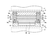
図1に示すように、支承装置10は、橋桁等の上部構造物1と橋脚や橋台といった下部構造物2との間に装着して水平荷重や鉛直荷重、回転荷重等の各種の荷重を支えると共に、地震や風、動的又は静的交通荷重等による揺動や振動、応力を吸収、分散しつつ、支承する橋梁用支承装置である。この支承装置10は、第一剛性体としての上沓11と第二剛性体としての下沓12との間に支承体となる弾性体13が介在されている。また、弾性体13は、上沓11又は下沓12(ここでは上沓11)に固定された拘束体16によって囲繞されている。
[1. Description of bearing device]
As shown in FIG. 1, a bearing device 10 is mounted between an upper structure 1 such as a bridge girder and a lower structure 2 such as a bridge pier or an abutment to support various loads such as a horizontal load, a vertical load, and a rotational load. At the same time, it is a bridge support device that supports and absorbs and disperses vibrations, vibrations and stresses caused by earthquakes, winds, dynamic or static traffic loads, and the like. In the support device 10, an elastic body 13 serving as a support body is interposed between an upper collar 11 serving as a first rigid body and a lower collar 12 serving as a second rigid body. The elastic body 13 is surrounded by a restraining body 16 fixed to the upper collar 11 or the lower collar 12 (here, the upper collar 11).

上沓11は、金属やセラミックス、或いは硬質樹脂やFRPの如くの強化樹脂等の剛性素材によって構成することが好ましいが、必ずしも剛性素材に限定されるものではなく、弾性素材や剛性素材と弾性素材との組合せによって構成される材料によっても構成することが出来る。各種素材から構成される上沓11は、平面形状が略多角形、略円形、略長円径、略楕円形等の適宜の形状に設定することが出来るが、方形又は円形とすることが製造上、或いは施工上、交換上有利である。なお、上沓11は、外表面を全体的に弾性体等の被覆層で覆って、耐候性、防錆効果を得るように構成しても良い。   The upper arm 11 is preferably made of a rigid material such as metal, ceramics, or a hard resin or a reinforced resin such as FRP, but is not necessarily limited to a rigid material. It can also comprise by the material comprised by a combination. The upper collar 11 made of various materials can be set to an appropriate shape such as a substantially polygonal shape, a substantially circular shape, a substantially oval diameter, or a substantially elliptical shape in plan view. It is advantageous in terms of replacement from the top or construction. In addition, you may comprise the upper collar 11 so that an outer surface may be entirely covered with coating layers, such as an elastic body, and a weather resistance and a rust prevention effect may be acquired.

上部構造物1に対する上沓11の固定手段は、例えばボルト、ナット等の締結手段を用いて上沓11を上部構造物に対して直接的に固定しても良いが、ここでは、上沓11よりも広面積の板状をなす上部プレート3を用いて上沓11を上部構造物1に対して間接的に固定している。上沓11の上部構造物1への固定方法は、これらの例に限定されるものではない。   As a means for fixing the upper collar 11 to the upper structure 1, the upper collar 11 may be directly secured to the upper structure using fastening means such as bolts and nuts. The upper plate 11 is indirectly fixed to the upper structure 1 using the upper plate 3 having a plate shape with a larger area. The method for fixing the upper collar 11 to the upper structure 1 is not limited to these examples.

なお、可動支承装置として用いるとき等は、上沓11の上部、例えば上沓11と上部プレート3との間に摺滑部材4を配設して、上部構造物1と支承装置10とを相対変位可能に固定しても良い。この摺滑部材4としては、例えば、フッ化炭素樹脂の一種であるポリテトラフルオロエチレン(PTFE)の如くの低摩擦係数の表面を有するプレート等を、上沓11の上面に固定したり、又は上部構造物1や上部構造物1に固定される取付手段側の下面に固定することによって構成することが可能である。   When used as a movable support device, the sliding member 4 is disposed above the upper rod 11, for example, between the upper rod 11 and the upper plate 3, so that the upper structure 1 and the support device 10 are relative to each other. You may fix so that displacement is possible. As the sliding member 4, for example, a plate having a surface with a low coefficient of friction such as polytetrafluoroethylene (PTFE) which is a kind of fluorocarbon resin is fixed to the upper surface of the upper collar 11, or It can be configured by being fixed to the upper structure 1 or the lower surface on the attachment means side fixed to the upper structure 1.

下沓12は、上沓11同様、金属やセラミックス、或いは硬質樹脂やFRPの如くの強化樹脂等の剛性素材によって構成することが好ましいが、必ずしも剛性素材に限定されるものではなく、弾性素材や剛性素材と弾性素材との組合せによっても構成される材料によって構成することが出来る。各種素材から構成される下沓12は、平面形状が略多角形、略円形、略長円径、略楕円形等の適宜の形状に設定することが出来るが、方形又は円形とすることが製造上、又は施工上、交換上で有利である。下沓12の平面形状等は、必ずしも上沓11と一致させる必要はないが、各部のサイズと、凸部や凹部の形状や位置等は下沓12の設定と上沓11の設定を互いに整合させる必要がある。なお、下沓12は、外表面を全体的に弾性体等の被覆層で覆って、耐候性、防錆効果を得るように構成することも出来る。   The lower arm 12 is preferably composed of a rigid material such as metal, ceramics, or a reinforced resin such as a hard resin or FRP, but is not necessarily limited to a rigid material. It can be constituted by a material constituted by a combination of a rigid material and an elastic material. The lower bar 12 made of various materials can be set to an appropriate shape such as a substantially polygonal shape, a substantially circular shape, a substantially oval diameter, or a substantially oval shape in plan view. It is advantageous in terms of top, construction, and replacement. The planar shape or the like of the lower eyelid 12 does not necessarily match the upper eyelid 11, but the size of each part, the shape and position of the convex portion and the recessed portion, etc. match the setting of the lower eyelid 12 and the setting of the upper eyelid 11. It is necessary to let In addition, the lower eyelid 12 can also be comprised so that an outer surface may be entirely covered with coating layers, such as an elastic body, and a weather resistance and a rust prevention effect may be acquired.

下部構造物に対する下沓12の固定手段は、例えばボルト、ナット等の締結手段を用いて下沓12を下部構造物2に対して直接的に固定しても良いが、ここでは、下沓12よりも広面積の板状をなす下部プレート5の如くの下部固定手段を用いて下沓12を下部構造物2に対して間接的に固定している。下沓12の下部構造物2への固定方法は、これらの例に限定されるものではない。   As a fixing means of the lower rod 12 with respect to the lower structure, for example, the lower rod 12 may be directly fixed to the lower structure 2 by using fastening means such as bolts and nuts. The lower rod 12 is indirectly fixed to the lower structure 2 using lower fixing means such as the lower plate 5 having a plate shape with a larger area. The method for fixing the lower rod 12 to the lower structure 2 is not limited to these examples.

なお、可動支承装置として用いるとき等は、下沓12の下部、例えば下部プレート5と下沓12との間に摺滑部材6を配設して、下部構造物2と支承装置10とを相対変位可能に固定しても良い。この摺滑部材6としては、例えば、PTFEの如くの低摩擦係数の表面を有するプレート等を、下沓12の下面に固定したり、又は下部構造物2や下部構造物2に固定される取付手段側の上面に固定することが可能である。   When used as a movable bearing device, a sliding member 6 is disposed below the lower rod 12, for example, between the lower plate 5 and the lower rod 12, so that the lower structure 2 and the bearing device 10 are relative to each other. You may fix so that displacement is possible. As the sliding member 6, for example, a plate having a low coefficient of friction surface such as PTFE is fixed to the lower surface of the lower rod 12, or the lower structure 2 or the lower structure 2 is fixed. It is possible to fix to the upper surface on the means side.

尚、上沓11や下沓12の直接的又は間接的な固定は、着脱可能な方法とするのが好ましく、ボルト、ナット等による締結はその一例である。   The direct or indirect fixing of the upper rod 11 and the lower rod 12 is preferably a detachable method, and fastening with bolts, nuts, etc. is an example.

[2.弾性体及び拘束体の説明]
弾性体13は、天然ゴムや合成ゴム、熱可塑性エラストマや熱硬化性エラストマを用いることができ、これらの中でも天然ゴムを主成分として使用することが好ましい。具体的なエラストマ成分としては、例えば、天然ゴム(NR)、ポリイソプレンゴム(IR)、ポリブタジエンゴム(BR)、スチレン−ブタジエンゴム(SBR)、クロロプレンゴム(CR)、エチレン−プロピレンゴム、ブチルゴム(IIR)、ハロゲン化ブチルゴム(臭素化、塩素化等)、アクリルゴム、ポリウレタン、シリコーンゴム、フッ化ゴム、多硫化ゴム、ハイパロン、エチレン酢酸ビニルゴム、エピクロルヒドリンゴム、エチレン−メチルアクリレート共重合体、スチレン系エラストマ、ウレタン系エラストマ、ポリオレフィン系エラストマ、アクリロニトリル−ブタジエンゴム(NBR)、スチレン・イソプレン・スチレンブロック共重合体(SIS)、エポキシ化天然ゴム、trans−ポリイソプレン、ノルボルネン開環重合体(ポリノルボルネン)、スチレンブタジエンゴム(SBR)、ハイスチレン樹脂、イソプレンゴム等のゴムを一種単独、或いは二種以上を併用することが出来る。
[2. Explanation of elastic body and restraint body]
As the elastic body 13, natural rubber, synthetic rubber, thermoplastic elastomer or thermosetting elastomer can be used, and among these, natural rubber is preferably used as a main component. Specific elastomer components include, for example, natural rubber (NR), polyisoprene rubber (IR), polybutadiene rubber (BR), styrene-butadiene rubber (SBR), chloroprene rubber (CR), ethylene-propylene rubber, butyl rubber ( IIR), halogenated butyl rubber (brominated, chlorinated, etc.), acrylic rubber, polyurethane, silicone rubber, fluorinated rubber, polysulfide rubber, hyperon, ethylene vinyl acetate rubber, epichlorohydrin rubber, ethylene-methyl acrylate copolymer, styrene series Elastomer, urethane elastomer, polyolefin elastomer, acrylonitrile-butadiene rubber (NBR), styrene-isoprene-styrene block copolymer (SIS), epoxidized natural rubber, trans-polyisoprene, norbornene Ring polymer (polynorbornene), styrene-butadiene rubber (SBR), high styrene resin, a rubber such as isoprene rubber alone, or may be used in combination of two or more.

図2に示す弾性体13aは、例えば、円柱状をなし、内部に鉄板といった剛性の補強板が設けられていない弾性層が一つ(単層)のものを示している。この弾性体13aの側面には、周回り方向に、凸部14と凹部15とが設けられている。凸部14と凹部15は、図2の例では、互いに平行に、周回り方向に連続して設けられている。   The elastic body 13a shown in FIG. 2 has, for example, a cylindrical shape and one (single layer) elastic layer in which a rigid reinforcing plate such as an iron plate is not provided. A convex portion 14 and a concave portion 15 are provided on the side surface of the elastic body 13a in the circumferential direction. In the example of FIG. 2, the convex portion 14 and the concave portion 15 are provided in parallel to each other and continuously in the circumferential direction.

なお、凸部14と凹部15は、周回り方向に断続的に設けられていても良い。更に、凸部14と凹部15は、厚さ方向の間隔も、等間隔でも、等間隔でなくても良い。更に、図3に示すように、弾性体13としては、高さ(厚さ)方向に、凸部14や凹部15を設けたものであっても良い。更に、図4に示すように、弾性体13としては、側面に凸部14や凹部15を有しないものであってもよい。   The convex portion 14 and the concave portion 15 may be provided intermittently in the circumferential direction. Furthermore, the convex portion 14 and the concave portion 15 do not have to be spaced in the thickness direction at regular intervals or at regular intervals. Furthermore, as shown in FIG. 3, the elastic body 13 may be provided with convex portions 14 and concave portions 15 in the height (thickness) direction. Furthermore, as shown in FIG. 4, the elastic body 13 may not have the convex portion 14 or the concave portion 15 on the side surface.

以上のような弾性体13は、図1に示す例では、下沓12上に配設され、下沓12によって支持される。弾性体13は、上沓11と下沓12との間を接着して高支圧化しても良いが、接着しないことにより、良好な回転追従性を実現することも出来る。   In the example shown in FIG. 1, the elastic body 13 as described above is disposed on the lower collar 12 and supported by the lower collar 12. The elastic body 13 may be bonded to the upper collar 11 and the lower collar 12 to increase the bearing pressure. However, by not bonding, the elastic follower 13 can also achieve good rotation followability.

また、弾性体13は、図1に示すように、拘束体16によって囲繞されている。拘束体16は、弾性体13の外径よりやや大きい内径を有する円筒体であり、上沓11又は下沓12の何れか、図1では上沓11の外周部に固定されている。例えば、上沓11と拘束体16との結合は、ボルト・ナット等の固定手段16bを用いても良い。なお、固定手段16bとしては、上沓11と拘束体16の何れか一方に雄ねじを設け、他方に雌ねじを設け、これらを互いに螺合して結合するねじ締結によったり、溶接したり、従来公知の結合方法等で行うことも出来る。拘束体16の下沓12側の先端部は、下沓12の外周部の外側に位置し、固定されていない。これにより、上沓11は、鉛直荷重の入力があっとき、弾性体13を圧縮しながら鉛直下向きに移動することが出来る。すなわち、拘束体16の下沓12側の先端部が下沓12の外周部の外側に位置することで、上沓11と下沓12の間に配設される弾性体13の剪断変形を抑制する機能や、弾性体13を略密閉状態に拘束して高支圧化させるピストンの役割を実現する。かくして、下沓12に支持された弾性体13は、上面が上沓11、側面が拘束体16によって包囲され、略密閉された空間に配設されることになる。支承装置10は、略密閉ゴム支承となり、小さな支承面積にして高荷重を支承することが可能となる。   Moreover, the elastic body 13 is surrounded by the restraint body 16, as shown in FIG. The restraining body 16 is a cylindrical body having an inner diameter slightly larger than the outer diameter of the elastic body 13, and is fixed to either the upper collar 11 or the lower collar 12, or the outer periphery of the upper collar 11 in FIG. 1. For example, the upper rod 11 and the restraining body 16 may be coupled using a fixing means 16b such as a bolt / nut. As the fixing means 16b, either one of the upper collar 11 and the restraining body 16 is provided with a male screw, and the other is provided with a female screw. It can also be performed by a known bonding method. The tip of the restraining body 16 on the lower collar 12 side is located outside the outer peripheral portion of the lower collar 12 and is not fixed. As a result, the upper rod 11 can move vertically downward while compressing the elastic body 13 when a vertical load is input. In other words, the tip of the restraining body 16 on the lower collar 12 side is located outside the outer periphery of the lower collar 12, thereby suppressing the shear deformation of the elastic body 13 disposed between the upper collar 11 and the lower collar 12. And the function of a piston that restrains the elastic body 13 in a substantially sealed state to increase the bearing pressure. Thus, the elastic body 13 supported by the lower collar 12 is disposed in a substantially sealed space with the upper surface surrounded by the upper collar 11 and the side surface by the restraining body 16. The bearing device 10 is a substantially sealed rubber bearing, and can support a high load with a small bearing area.

ここで、弾性体13と拘束体16との大きさの関係について説明すると、図1の例では、支承装置10が上部構造物1と下部構造物2との間に設置され、支承装置10に対して上部構造物1の荷重によって弾性体13が変形している状態において、弾性体13の側面の凸部14が拘束体16の内周面の拘束面16aに当接した状態となっている。つまり、図5に示すように、上部構造物1と下部構造物2との間に設置される前は、弾性体13の側面の凸部14が拘束体16の内周面の拘束面16aとの間が非接触の状態で、隙間が設けられた状態となっており、上部構造物1と下部構造物2との間に設置されると、上部構造物1の死荷重によって、弾性体13の側面の凸部14が拘束体16の内周面の拘束面16aに当接した状態となる。なお、通常の使用範囲での荷重の際には、弾性体13の側面の凸部14が拘束体16の内周面の拘束面16aと非接触で、通常の使用範囲を超える高い荷重があった際に、弾性体13の側面の凸部14が拘束体16の内周面の拘束面16aと当接し、更なる高荷重の入力によって拘束面16aに凸部14、並びに、凹部15の膨出変形した部分が圧接されるようにしても良い。   Here, the size relationship between the elastic body 13 and the restraint body 16 will be described. In the example of FIG. 1, the support device 10 is installed between the upper structure 1 and the lower structure 2, and On the other hand, in a state where the elastic body 13 is deformed by the load of the upper structure 1, the convex portion 14 on the side surface of the elastic body 13 is in contact with the restraining surface 16 a on the inner peripheral surface of the restraining body 16. . That is, as shown in FIG. 5, before the installation between the upper structure 1 and the lower structure 2, the convex portion 14 on the side surface of the elastic body 13 is connected to the restraining surface 16 a on the inner peripheral surface of the restraining body 16. Is in a non-contact state between the upper structure 1 and the lower structure 2, the elastic body 13 is caused by the dead load of the upper structure 1 when installed between the upper structure 1 and the lower structure 2. The side surface convex portion 14 is in contact with the restraining surface 16 a on the inner peripheral surface of the restraining body 16. When the load is in the normal use range, the convex portion 14 on the side surface of the elastic body 13 is not in contact with the restraining surface 16a on the inner peripheral surface of the restraint body 16, and there is a high load exceeding the normal use range. In this case, the convex portion 14 on the side surface of the elastic body 13 comes into contact with the constraining surface 16a on the inner peripheral surface of the constraining body 16, and the convex portion 14 and the concave portion 15 are expanded on the constraining surface 16a by the input of a further high load. The deformed part may be pressed.

更に、図6に示すように、上部構造物1と下部構造物2との間に設置される前において、弾性体13の側面の凸部14が拘束体16の内周面の拘束面16aに当接した状態であっても良い。この場合、弾性体13を拘束体16内に配設する際、拘束体16内における弾性体13を正確に位置決めすることが出来る。   Further, as shown in FIG. 6, the convex portion 14 on the side surface of the elastic body 13 is formed on the restraining surface 16 a on the inner peripheral surface of the restraining body 16 before being installed between the upper structure 1 and the lower structure 2. It may be in a contact state. In this case, when the elastic body 13 is disposed in the restraining body 16, the elastic body 13 in the restraining body 16 can be accurately positioned.

以上のように、本発明で用いる弾性体13は、弾性体13の側面に凸部14を設け、凸部14以外を凹部15とすることによって、弾性体13に鉛直荷重が加わった際に、鉛直下向きに変位するようにし、更に、拘束体16によって、弾性体13の変形量が制限される構成となっている。従って、このような作用を実現出来るのであれば、弾性体13の側面に設ける凸部14と凹部15を設ける位置や大きさは、上述の例に限定されるものではない。   As described above, when the elastic body 13 used in the present invention is provided with the convex portion 14 on the side surface of the elastic body 13 and the concave portion 15 other than the convex portion 14, when a vertical load is applied to the elastic body 13, Further, it is configured to be displaced vertically downward, and further, the amount of deformation of the elastic body 13 is limited by the restraining body 16. Therefore, as long as such an action can be realized, the positions and sizes of the convex portions 14 and the concave portions 15 provided on the side surfaces of the elastic body 13 are not limited to the above examples.

[3.支承装置の動作説明]
以上のような支承装置10では、上部構造物1と下部構造物2との間に設置されると、図1に示すように、弾性体13が、通常の使用範囲の荷重(例えば死荷重や死荷重+車両通行時の活荷重)によって、圧縮され、弾性体13の凸部14は、弾性体13を囲繞した拘束体16の拘束面16aに近接又は当接した位置となる。支承装置10は、弾性体13が鉛直荷重の大きさに応じた弾性変形をし、この弾性変形によって側面の凸部14が凹部15により構成された隙間を埋めるように変形しながら、拘束体16の拘束面16aに圧接される。すなわち、弾性体13の変位量は、拘束体16によって制限される。
[3. Explanation of operation of bearing device]
In the support device 10 as described above, when installed between the upper structure 1 and the lower structure 2, as shown in FIG. 1, the elastic body 13 has a load in a normal use range (for example, dead load or (Dead load + live load during vehicle travel) is compressed, and the convex portion 14 of the elastic body 13 is positioned close to or in contact with the restraining surface 16a of the restraining body 16 surrounding the elastic body 13. In the support device 10, the elastic body 13 is elastically deformed according to the magnitude of the vertical load, and the elastic body 13 is deformed so that the convex portion 14 on the side surface fills the gap formed by the concave portion 15. Is pressed against the constraining surface 16a. That is, the displacement amount of the elastic body 13 is limited by the restraining body 16.

このような支承装置10では、下沓12に支持された弾性体13を、上沓11と拘束体16によって囲繞し、弾性体13の側面と拘束面16aとの間に所定の隙間を有する略密閉された空間部を設けて構成することで、重入力の初期や低荷重の入力時には、鉛直荷重に対する鉛直可撓変位を可能としながら入力の高荷重化に伴って、徐々に鉛直変位量の増加量が小さくなって弾性率が高くなり、大きな荷重の入力に対しては密閉ゴム支承のように挙動して、小さな支承面積にして高荷重支持を実現する。また、低荷重から高荷重の入力に亘って鉛直面内における回転力の作用時には、弾性体13が拘束体16によって部分的に支持されながらも弾性体13と拘束体16との間の隙間により弾性体13が変形し、弾性体への極端な負荷なく、良好な回転追従性を実現出来る。   In such a support device 10, the elastic body 13 supported by the lower rod 12 is surrounded by the upper rod 11 and the restraining body 16, and a predetermined gap is provided between the side surface of the elastic body 13 and the restraining surface 16 a. By providing a sealed space, the vertical displacement amount gradually increases as the input becomes heavier while enabling vertical flexible displacement with respect to the vertical load at the initial stage of heavy input or when inputting low load. As the amount of increase decreases, the modulus of elasticity increases, and when a large load is input, it behaves like a hermetic rubber bearing and realizes high load support with a small bearing area. In addition, when a rotational force is applied in the vertical plane from a low load to a high load, the elastic body 13 is partially supported by the restraining body 16, but the clearance between the elastic body 13 and the restraining body 16 The elastic body 13 is deformed, and good rotation followability can be realized without an extreme load on the elastic body.

ここで、図7に、鉛直方向の変位量と鉛直荷重との関係を示す。
線A・・・密閉ゴム支承ではなく、荷重が加わった際の変位が拘束されていないゴム支承。
線B・・・拘束体16の内径(ポット部の内径)に対して弾性体13の外形を小さくし、凸部14と凹部15を大きく形成して、拘束面16aと弾性体13の側面との間の隙間を大きくしたときの特性を示す。(隙間大)
線C・・・拘束面16aと弾性体13の側面との間の隙間を線Bの場合より小さくしたときの特性を示す。(隙間中)
線D・・・拘束面16aと弾性体13の側面との間の隙間を最も小さくしたときの特性を示す。(隙間小)
線E・・・拘束面16aと弾性体13の側面との間の隙間を設けない密閉ゴム支承。回転追従性能を有するが、鉛直方向の弾性変位はほとんど無く、金属支承の扱いとなる。
Here, FIG. 7 shows the relationship between the amount of displacement in the vertical direction and the vertical load.
Line A: Not a sealed rubber bearing, but a rubber bearing whose displacement when a load is applied is not constrained.
Line B: The outer shape of the elastic body 13 is made smaller than the inner diameter of the restraining body 16 (the inner diameter of the pot portion), the convex portions 14 and the concave portions 15 are formed larger, and the restraining surface 16a and the side surface of the elastic body 13 The characteristics when the gap between them is increased are shown. (Large gap)
Line C: Characteristic when the gap between the restraining surface 16a and the side surface of the elastic body 13 is made smaller than that of the line B. (In the gap)
Line D: shows characteristics when the gap between the restraining surface 16a and the side surface of the elastic body 13 is minimized. (Small gap)
Line E: A sealed rubber bearing that does not provide a gap between the restraining surface 16a and the side surface of the elastic body 13. Although it has a rotation follow-up performance, it has almost no elastic displacement in the vertical direction and is handled as a metal bearing.

図7の線Aで示すゴム支承では、鉛直荷重が大きくなるに連れて鉛直変位量もほぼ比例的に大きくなり、グラフの傾き(拘束度又はバネ定数)はほぼ一定である。弾性体13の側面に凸部14と凹部15を設けた線B−Dの例によれば、鉛直荷重が大きくなるに連れて鉛直変位量も大きくなるが、その特性は非線形となる。すなわち、鉛直変位に対する鉛直荷重反力の大きさを表すグラフの傾き(拘束度又はバネ定数)は、鉛直変位が大きくなるほど大きくなる。このように、弾性体13の側面に凸部14と凹部15を設けたときには、大きな荷重が入力されたときほど、より高度な密閉状態に変化して鉛直変位量の増加量が小さくなるような特性で、すなわち拘束度を可変として、上部構造物1を支承することが出来る。すなわち、この支承装置10では、適度な鉛直可撓性を有しながら高荷重を支持することが出来る。また、線B−Dの例を見ると、隙間が小さい程、鉛直変位に対する鉛直荷重反力の大きさを表すグラフの傾きの緩やかな範囲(一次勾配)を狭く設定することが出来る。すなわち、鉛直変位が小さくなる。更に、線Eの密閉ゴム支承では、鉛直方向の弾性変位はほとんど見られない。   In the rubber bearing shown by line A in FIG. 7, as the vertical load increases, the amount of vertical displacement increases substantially proportionally, and the slope (constraint or spring constant) of the graph is substantially constant. According to the example of the line BD in which the convex portion 14 and the concave portion 15 are provided on the side surface of the elastic body 13, the amount of vertical displacement increases as the vertical load increases, but the characteristics are nonlinear. That is, the inclination (constraint degree or spring constant) of the graph representing the magnitude of the vertical load reaction force with respect to the vertical displacement increases as the vertical displacement increases. Thus, when the convex part 14 and the recessed part 15 are provided in the side surface of the elastic body 13, it changes to a more advanced sealed state and the increase amount of a vertical displacement amount becomes small, so that a big load is input. The upper structure 1 can be supported by characteristics, that is, with the degree of restraint being variable. In other words, the bearing device 10 can support a high load while having appropriate vertical flexibility. Moreover, when the example of line BD is seen, the gentle range (primary gradient) of the inclination of the graph showing the magnitude | size of the vertical load reaction force with respect to a vertical displacement can be set narrowly, so that a clearance gap is small. That is, the vertical displacement is reduced. Furthermore, in the sealed rubber bearing of line E, there is almost no elastic displacement in the vertical direction.

特に、弾性体13の側面に凸部14と凹部15を設けた線B−Dの例によれば、高荷重が加わると、鉛直可撓変位が小さくなり、密閉ゴム支承のように挙動する。したがって、線B−Dの例では、支承する上部構造物1の種類、用途等に応じて、線B−Dの使用範囲を設定していくことになる。例えば、死荷重に活荷重が加わったとき、グラフの急勾配の範囲(二次勾配)の領域に含まれるようにすることで、車両通過時の振動や騒音を低減することが出来るようになる。なお、鉛直撓みがあるため、線B−Dの支承装置は、弾性支承装置に属する扱いとし得る。   In particular, according to the example of the line BD in which the convex portion 14 and the concave portion 15 are provided on the side surface of the elastic body 13, when a high load is applied, the vertical flexible displacement becomes small and behaves like a sealed rubber bearing. Therefore, in the example of the line BD, the use range of the line BD is set according to the type, application, etc. of the superstructure 1 to be supported. For example, when a live load is added to the dead load, it is possible to reduce vibration and noise when passing through the vehicle by including it in the steep slope range (secondary slope) of the graph. . Since there is vertical deflection, the bearing device of line BD can be treated as belonging to the elastic bearing device.

[4.積層型弾性体の説明]
以上の例では、弾性層が単層の弾性体13を用いた支承装置10を説明したが、弾性体13としては、図8に示すように、弾性層と補強板とが積層された積層構造の弾性体17であっても良い。弾性体17は、内部に補強板17aが設けられ、弾性層17bが複数設けられ、補強板17aと弾性層17bとが加硫接着によって相互に接着されている。単層の弾性体13は、荷重が加わると、自由側面が側方に押し出され、特に厚さ方向の中央部を中心として膨出する。積層型の弾性体17では、補強板17aがあることで、弾性体17の自由側面の膨出が抑制され、耐荷力が増大する。但し、補強板17aの間の弾性層17bの側面も、自由側面であるから荷重の大きさに応じて、側方に僅かに膨出する。しかし、支承装置10では、拘束体16が弾性体17の変形を拘束するので膨出量は僅かとなる。
[4. Explanation of laminated elastic body]
In the above example, the supporting device 10 using the elastic body 13 having a single elastic layer has been described. As the elastic body 13, a laminated structure in which an elastic layer and a reinforcing plate are laminated as shown in FIG. The elastic body 17 may be used. The elastic body 17 includes a reinforcing plate 17a, a plurality of elastic layers 17b, and the reinforcing plate 17a and the elastic layer 17b are bonded to each other by vulcanization bonding. When a load is applied to the single-layer elastic body 13, the free side surface is pushed out to the side, and in particular, bulges around the central portion in the thickness direction. In the laminated elastic body 17, since the reinforcing plate 17 a is provided, swelling of the free side surface of the elastic body 17 is suppressed, and the load bearing capacity is increased. However, since the side surface of the elastic layer 17b between the reinforcing plates 17a is also a free side surface, it slightly bulges to the side according to the load. However, in the support device 10, the restraint body 16 restrains the deformation of the elastic body 17, so that the bulging amount is small.

つまり、図8に示すように、積層型の弾性体17では、側面において、自由側面の弾性層17bの位置に凸部18を設け、補強板17aの位置に凹部19を設けるようにしている。この場合、凸部18は、荷重が加わった際、弾性層17bの自由側面が膨出することで、凹部19より先に拘束体16の拘束面16aに強く圧接されることになる。勿論、本発明では、図9に示すように、補強板17aの位置を凸部18とし、弾性層17bの位置を凹部19としても良い。この場合、凹部19となっている弾性層17bの自由側面が僅かに膨出することで、凸部18と凹部19の部分が同じように拘束体16の拘束面16aと当接され均等に圧接されるようにすることが出来る。積層型の弾性体17は、従来最も膨出量が多い補強板間位置の弾性部であるが、この部位に凸部18を設けた上、拘束体16の拘束面16aによってこの凸部18周辺の膨出量が拘束されているので、高荷重が入力されている際でも内部の補強板17aの周囲における弾性層17bに対する局部応力が緩和される。また、内部の補強板17aが高荷重によってもつぶれにくくなり、補強板17aを薄くすることが出来、支承装置10の全体の厚さの薄型化を実現出来る。   That is, as shown in FIG. 8, in the laminated elastic body 17, on the side surface, the convex portion 18 is provided at the position of the elastic layer 17b on the free side surface, and the concave portion 19 is provided at the position of the reinforcing plate 17a. In this case, when the load is applied, the convex portion 18 comes into strong pressure contact with the restraining surface 16a of the restraining body 16 before the concave portion 19 because the free side surface of the elastic layer 17b bulges. Of course, in the present invention, as shown in FIG. 9, the position of the reinforcing plate 17 a may be the convex portion 18 and the position of the elastic layer 17 b may be the concave portion 19. In this case, the free side surface of the elastic layer 17b which is the recess 19 slightly bulges, so that the convex portion 18 and the concave portion 19 are in contact with the restraint surface 16a of the restraint body 16 in the same manner and are evenly pressed. Can be done. The laminated elastic body 17 is the elastic portion at the position between the reinforcing plates that has the largest bulging amount in the past. The convex portion 18 is provided at this portion, and the periphery of the convex portion 18 is restricted by the restraining surface 16 a of the restraining body 16. Therefore, even when a high load is input, local stress on the elastic layer 17b around the internal reinforcing plate 17a is relieved. Further, the internal reinforcing plate 17a is not easily crushed by a high load, and the reinforcing plate 17a can be thinned, and the entire thickness of the support device 10 can be reduced.

積層型弾性体17と拘束体16との大きさの関係については、弾性体13の場合と同様で、図5や図6を用いて説明したように、設置前において、弾性体17の側面の凸部18が拘束体16の内周面の拘束面16aとの間が非接触の状態であっても良いが、接触した状態としても良く、この場合、組立時に、弾性体17の側面の凸部18が拘束体16の内周面の拘束面16aと接触するようになり、位置決め性が向上するので好ましい。しかしながら入力が無い時点での弾性体と拘束体との接触の有無は特に限定されるものではなく、例えば、大きな荷重が入力されたときに、弾性体17の側面の凸部18が拘束体16の内周面の拘束面16aと接触するようにしても良い。   The size relationship between the laminated elastic body 17 and the restraining body 16 is the same as that of the elastic body 13, and as described with reference to FIG. 5 and FIG. The convex portion 18 may be in a non-contact state with the constraining surface 16a on the inner peripheral surface of the constraining body 16, but may be in a contact state. The portion 18 comes into contact with the restraining surface 16a on the inner peripheral surface of the restraining body 16, which is preferable because positioning is improved. However, the presence / absence of contact between the elastic body and the restraint body at the time when there is no input is not particularly limited. For example, when a large load is inputted, the convex portion 18 on the side surface of the elastic body 17 becomes the restraint body 16. You may make it contact with the constraining surface 16a of the inner peripheral surface.

なお、図8及び図9の例では、上沓11と拘束体16とを一体に構成している。また、積層型の弾性体17は、鉛直荷重支持性能や水平荷重支持性能、並びに鉛直回転性能は、弾性層の面積や厚さ、材質、数、補強板の面積や厚さ、数等によって調節することが出来る。また。拘束体16は、上沓11の下面の外周側に固定されている。例えば、上沓11と拘束体16との結合は、ボルト・ナット等の固定手段16bを用いても良い。また、固定手段16bとしては、上沓11と拘束体16の何れか一方に雄ねじを設け、他方に雌ねじを設け、これらを互いに螺合して結合するねじ締結によったり、溶接したり、従来公知の結合方法等で行うことも出来る。   In the example of FIGS. 8 and 9, the upper collar 11 and the restraining body 16 are integrally formed. In the laminated elastic body 17, the vertical load support performance, horizontal load support performance, and vertical rotation performance are adjusted by the area and thickness of the elastic layer, the material and the number, the area and thickness of the reinforcing plate, the number, and the like. I can do it. Also. The restraining body 16 is fixed to the outer peripheral side of the lower surface of the upper collar 11. For example, the upper rod 11 and the restraining body 16 may be coupled using a fixing means 16b such as a bolt / nut. Further, as the fixing means 16b, either one of the upper collar 11 and the restraining body 16 is provided with a male screw, and the other is provided with a female screw. It can also be performed by a known bonding method.

[5.補強板の変形例の説明]
積層型の弾性体17に用いる補強板17aは、具体的に、図10に示すように構成することが出来る。図10(A)に示す例では、上沓11の弾性体17が配設される側の面の中央部に、突出部21aを設け、突出部21aの周囲に環状の凹部21bを設けている。また、下沓12の弾性体17が配設される側の面の中央部に、突出部22aを設け、突出部22aの周囲に凹部21bを設けている。したがって、上沓11と下沓12との間に配設される弾性体17は、中央部が薄肉部で、周囲が環状に厚肉部となっている。この弾性体17の内部には、厚肉部となる外周領域に、環状の補強板17aが設けられる。この弾性体17において、側面には、補強板17aの位置に凹部19が設けられ、弾性層17bの位置に凸部18が連続して又は断続的に設けられている。勿論、補強板17aの位置に凸部18を設け、弾性層17bの位置に凹部19を設けるようにしても良い。また、弾性体17の中央部には、拘束度調節のため、空隙部23aを設けるようにしても良い。このような弾性体17は、中央部が薄肉部で、周囲が環状の厚肉部となっているので、回転追従性を向上させることが出来る。
[5. Description of modification of reinforcing plate]
Specifically, the reinforcing plate 17a used for the laminated elastic body 17 can be configured as shown in FIG. In the example shown in FIG. 10 (A), a protrusion 21a is provided at the center of the surface of the upper collar 11 on the side where the elastic body 17 is disposed, and an annular recess 21b is provided around the protrusion 21a. . Moreover, the protrusion part 22a is provided in the center part of the surface by which the elastic body 17 of the lower collar 12 is arrange | positioned, and the recessed part 21b is provided in the circumference | surroundings of the protrusion part 22a. Therefore, the elastic body 17 disposed between the upper collar 11 and the lower collar 12 has a thin center portion and an annular thick portion around the periphery. Inside the elastic body 17, an annular reinforcing plate 17 a is provided in an outer peripheral region that becomes a thick portion. In the elastic body 17, a concave portion 19 is provided at a position of the reinforcing plate 17 a on the side surface, and a convex portion 18 is provided continuously or intermittently at the position of the elastic layer 17 b. Of course, the convex portion 18 may be provided at the position of the reinforcing plate 17a, and the concave portion 19 may be provided at the position of the elastic layer 17b. Moreover, you may make it provide the space | gap part 23a in the center part of the elastic body 17 for a restraint degree adjustment. Since such an elastic body 17 has a thin portion at the center and an annular thick portion around the center portion, it is possible to improve the rotation followability.

図10(B)は、図10(A)の変形例で、下沓12の弾性体17が配設される側の面が平坦に形成され、上沓11側のみに、突出部21aと凹部21bとが設けられている。この弾性体17では、下沓12の弾性体17が配設される側の面が平坦に形成されているので、下沓12や弾性体17の形状を簡素化することが出来、加工コストを削減出来る。この例でも、弾性体17の中央部に、空隙部23aを設けるようにしても良い。また、弾性体17の側面には、補強板17aの位置に凹部19が設けられ、弾性層17bの位置に凸部18が連続して又は断続的に設けられている。勿論、補強板17aの位置に凸部18を設け、弾性層17bの位置に凹部19を設けるようにしても良い。   FIG. 10 (B) is a modification of FIG. 10 (A), in which the surface on the side where the elastic body 17 of the lower eyelid 12 is disposed is formed flat, and only the upper eyelid 11 side has a protrusion 21a and a recess. 21b. In this elastic body 17, since the surface of the lower eyelid 12 on which the elastic body 17 is disposed is formed flat, the shape of the lower eyelid 12 and the elastic body 17 can be simplified, and the processing cost can be reduced. Can be reduced. Also in this example, the gap portion 23 a may be provided in the central portion of the elastic body 17. Further, on the side surface of the elastic body 17, a concave portion 19 is provided at the position of the reinforcing plate 17a, and a convex portion 18 is provided continuously or intermittently at the position of the elastic layer 17b. Of course, the convex portion 18 may be provided at the position of the reinforcing plate 17a, and the concave portion 19 may be provided at the position of the elastic layer 17b.

図10(C)は、弾性体17に同心に、環状の複数の補強板17aが同心円状に設けられている。この例では、上沓11と下沓12の相対する面、すなわち弾性体17が配設される面は平坦に形成されている。この例では、上沓11と下沓12の弾性体17が配設される面に突出部21a,22aや凹部21b,22b(図10(A),(B)参照)が設けられていないので、構成が簡素化され、加工コストを削減することが出来る。なお、複数の環状の補強板17aは、内周側に一つでも良く、また、外周側に一つでも良く、その数も特に限定されるものではない。また、図10(C)では、同じ高さに同心に環状の補強板17aを複数設けているが、各補強板17aの設けられる高さは、必ずしも同じで無くて良い。この例においても更に、弾性体17の中央部には、空隙部23aを設けるようにしても良い。更に、弾性体17の側面には、補強板17aの位置に凸部18が設けられ、弾性層17bの位置に凹部19が連続して又は断続的に設けられている。勿論、補強板17aの位置に凹部19を設け、弾性層17bの位置に凸部18を設けるようにしても良い。   In FIG. 10C, a plurality of annular reinforcing plates 17 a are provided concentrically with the elastic body 17. In this example, the opposed surfaces of the upper collar 11 and the lower collar 12, that is, the surface on which the elastic body 17 is disposed are formed flat. In this example, the protrusions 21a and 22a and the recesses 21b and 22b (see FIGS. 10A and 10B) are not provided on the surface on which the elastic body 17 of the upper and lower collars 11 and 12 is disposed. The structure is simplified and the processing cost can be reduced. The number of the plurality of annular reinforcing plates 17a may be one on the inner peripheral side or one on the outer peripheral side, and the number is not particularly limited. Further, in FIG. 10C, a plurality of annular reinforcing plates 17a are provided concentrically at the same height, but the heights at which the reinforcing plates 17a are provided are not necessarily the same. In this example as well, a gap 23a may be provided in the center of the elastic body 17. Further, on the side surface of the elastic body 17, a convex portion 18 is provided at the position of the reinforcing plate 17a, and a concave portion 19 is provided continuously or intermittently at the position of the elastic layer 17b. Of course, the concave portion 19 may be provided at the position of the reinforcing plate 17a, and the convex portion 18 may be provided at the position of the elastic layer 17b.

図10(D)は、複数の補強板17aが互いに離間して平行に設けられている。この例において、補強板17aの枚数は一枚でも複数枚でも良い。この例では、側面に、補強板17aの位置に凸部18が設けられ、弾性層17bの位置に凹部19が連続して又は断続的に設けられている。勿論、補強板17aの位置に凹部19を設け、弾性層17bの位置に凸部18を設けるようにしても良い。   In FIG. 10D, a plurality of reinforcing plates 17a are provided in parallel and spaced apart from each other. In this example, the number of reinforcing plates 17a may be one or more. In this example, a convex portion 18 is provided on the side surface at the position of the reinforcing plate 17a, and a concave portion 19 is provided continuously or intermittently at the position of the elastic layer 17b. Of course, the concave portion 19 may be provided at the position of the reinforcing plate 17a, and the convex portion 18 may be provided at the position of the elastic layer 17b.

図10(E)は、補強板17aの表裏に、複数の環状突出部17cが同心円状に設けられている。この例において、補強板17aの枚数は一枚でも複数枚でも良い。また、環状突出部17cの数は、特に限定されるものではなく、例えば一つであっても良い。また、環状突出部17cは、連続した突条部ではなく、断続的なものであっても良い。この例では、弾性体17の側面の補強板17aの位置に凸部18が設けられ、弾性層17bの位置に凹部19が連続して又は断続的に設けられている。勿論、補強板17aの位置に凹部19を設け、弾性層17bの位置に凸部18を設けるようにしても良い。また、環状突出部17cは、表裏の何れか一方の面のみに設けても良く、また、補強板17aは複数枚設けるようにしても良い。   In FIG. 10E, a plurality of annular protrusions 17c are provided concentrically on the front and back of the reinforcing plate 17a. In this example, the number of reinforcing plates 17a may be one or more. Further, the number of the annular protrusions 17c is not particularly limited, and may be one, for example. Moreover, the cyclic | annular protrusion part 17c may be an intermittent thing instead of a continuous protrusion part. In this example, the convex part 18 is provided in the position of the reinforcement board 17a of the side surface of the elastic body 17, and the recessed part 19 is provided in the position of the elastic layer 17b continuously or intermittently. Of course, the concave portion 19 may be provided at the position of the reinforcing plate 17a, and the convex portion 18 may be provided at the position of the elastic layer 17b. Further, the annular protrusion 17c may be provided on only one of the front and back surfaces, and a plurality of reinforcing plates 17a may be provided.

[6.支承装置の変形例1]
図11に示す支承装置30は、下沓12に、芯材31が取り付けられ、上揚防止部と水平変位防止部とを設けたものである。また、この支承装置30は、第一剛性体としての上沓11と第二剛性体としての下沓12との間に弾性層と補強板とが積層された積層構造の弾性体17が介在されている。支承装置30の上沓11は、表裏面に貫通した貫通孔32が穿設されている。貫通孔32には、上沓11の上面側から芯材31が挿入され、芯材31の先端部が上沓11の上面から突出することなく、上沓11が鉛直下向きに変位する分を考慮して、先端部が一段低くなるように収容されている。この貫通孔32の開口端には、上揚防止片32aがフランジ状に形成されている。
[6. Modification 1 of bearing device]
A support device 30 shown in FIG. 11 is provided with a core 31 attached to the lower rod 12 and provided with a lifting prevention portion and a horizontal displacement prevention portion. The bearing device 30 includes an elastic body 17 having a laminated structure in which an elastic layer and a reinforcing plate are laminated between an upper collar 11 as a first rigid body and a lower collar 12 as a second rigid body. ing. The upper collar 11 of the support device 30 has a through hole 32 penetrating through the front and back surfaces. The core material 31 is inserted into the through-hole 32 from the upper surface side of the upper collar 11, and the amount of displacement of the upper collar 11 vertically downward is considered without the tip portion of the core material 31 protruding from the upper surface of the upper collar 11. Thus, the tip portion is accommodated so as to be lowered one step further. A lifting prevention piece 32 a is formed in a flange shape at the opening end of the through hole 32.

貫通孔32に挿通される芯材31は、大径部33となる頭部を有する金属性のボルト状部材からなり、先端部である大径部33が上沓11の貫通孔32の内部に収容可能な大きさに設定されている。この芯材31は、上沓11の貫通孔32より弾性体17の略中央部に形成された挿通孔34に挿通され、更に、下沓12の弾性体17の支持面側に形成されたネジ穴35に螺合されることによって固定される。芯材31は、貫通孔32より挿入され、ネジ穴35に固定されたとき、大径部33が貫通孔32内に一段低くなるように収容される。この芯材31は、下沓12に固定されることで、上沓11と下沓12とが水平方向に相対変位しようとした際に、芯材31が上揚防止片32aの先端面又は貫通孔32の側面に突き当たり、下沓12に固定された芯材31によって上沓11の変位が規制される。すなわち、芯材31は、水平変位防止部として機能して、過剰に上沓11と下沓12とが水平方向において相対変位することを防止する。更に、芯材31の大径部33は、貫通孔32の上揚防止片32aの開口径より大きく、上揚防止片32aと係合する。芯材31は、上沓11に上揚力、すなわち上沓11が下沓12に対して相対的に上揚しようとする力が加わったとき、下沓12に固定された芯材31の大径部33に上揚防止片32aが係止されることによって、上沓11と下沓12とが乖離することを防止することが出来る。すなわち、大径部33は、上揚防止部としても機能することになる。   The core member 31 inserted into the through hole 32 is made of a metallic bolt-shaped member having a head that becomes the large diameter portion 33, and the large diameter portion 33, which is the tip portion, is inside the through hole 32 of the upper collar 11. It is set to a size that can be accommodated. The core material 31 is inserted into the insertion hole 34 formed in the substantially central portion of the elastic body 17 from the through hole 32 of the upper collar 11, and further, the screw formed on the support surface side of the elastic body 17 of the lower collar 12. It is fixed by being screwed into the hole 35. When the core material 31 is inserted from the through hole 32 and fixed to the screw hole 35, the large diameter portion 33 is accommodated in the through hole 32 so as to be lowered by one step. The core material 31 is fixed to the lower rod 12 so that when the upper rod 11 and the lower rod 12 are about to be displaced relatively in the horizontal direction, the core material 31 becomes the tip surface or the through hole of the lifting prevention piece 32a. The displacement of the upper collar 11 is regulated by the core 31 fixed to the lower collar 12 while hitting the side surface of the lower collar 32. That is, the core material 31 functions as a horizontal displacement prevention unit, and prevents the upper collar 11 and the lower collar 12 from being excessively displaced in the horizontal direction. Further, the large-diameter portion 33 of the core member 31 is larger than the opening diameter of the lifting prevention piece 32a of the through hole 32 and engages with the lifting prevention piece 32a. The core material 31 has a large-diameter portion of the core material 31 fixed to the lower collar 12 when an upward lifting force is applied to the upper collar 11, that is, a force that the upper collar 11 attempts to lift relative to the lower collar 12. When the lifting prevention piece 32 a is locked to the 33, it is possible to prevent the upper collar 11 and the lower collar 12 from separating. That is, the large diameter part 33 functions also as a lifting prevention part.

また、弾性体17は、図11に示すように、拘束体16によって囲繞されている。拘束体16は、弾性体13の平均外径よりやや大きい内径を有する円筒体であり、上沓11の外周部に固定されている。例えば、上沓11と拘束体16との結合は、ボルト・ナット等の固定手段16bを用いても良い。なお、固定手段16bとしては、上沓11と拘束体16の何れか一方に雄ねじを設け、他方に雌ねじを設け、これらを互いに螺合して結合するねじ締結によったり、溶接したり、従来公知の結合方法等で行うことが出来る。   Moreover, the elastic body 17 is surrounded by the restraint body 16, as shown in FIG. The restraining body 16 is a cylindrical body having an inner diameter slightly larger than the average outer diameter of the elastic body 13, and is fixed to the outer peripheral portion of the upper collar 11. For example, the upper rod 11 and the restraining body 16 may be coupled using a fixing means 16b such as a bolt / nut. As the fixing means 16b, either one of the upper collar 11 and the restraining body 16 is provided with a male screw, and the other is provided with a female screw. It can be performed by a known bonding method or the like.

拘束体16の下沓12側の先端部は、下沓12の外周部の外側に位置し、固定されていない。これにより、上沓11は、鉛直荷重の入力があっとき、弾性体13を圧縮しながら鉛直下向きに変位することが出来る。すなわち、拘束体16の下沓12側の先端部が下沓12の外周部の外側に位置することで、芯材31と協働して、上沓11と下沓12の間に配設される弾性体17の剪断変形を抑制する機能や、弾性体17を略密閉状態に拘束して高支圧化させるシリンダの役割を果たす。かくして、下沓12に支持された弾性体17は、上面が上沓11、側面が拘束体16によって包囲され、略密閉された空間に配設されることになる。すなわち、支承装置10は、略密閉ゴム支承となり、小さな支承面積にして高荷重を支承することが可能となる。   The tip of the restraining body 16 on the lower collar 12 side is located outside the outer peripheral portion of the lower collar 12 and is not fixed. As a result, when the vertical load is input, the upper collar 11 can be displaced vertically downward while compressing the elastic body 13. That is, the distal end portion of the restraining body 16 on the lower collar 12 side is located outside the outer peripheral portion of the lower collar 12, so that it is disposed between the upper collar 11 and the lower collar 12 in cooperation with the core member 31. The function of suppressing the shear deformation of the elastic body 17 and the role of a cylinder that restrains the elastic body 17 in a substantially sealed state to increase the bearing pressure. Thus, the elastic body 17 supported by the lower collar 12 is disposed in a substantially sealed space with the upper surface surrounded by the upper collar 11 and the side surface by the restraining body 16. That is, the bearing device 10 is a substantially sealed rubber bearing, and can support a high load with a small bearing area.

このような支承装置30にあっても、上述した支承装置10と同様に、下沓12に支持された弾性体17を、上沓11と拘束体16によって囲繞することで、略密閉された空間部を構成して、略密閉ゴム支承のようにして小さな支承面積にして高荷重支承を実現しながら、弾性体17の側面と拘束面16aとの間に隙間を設けることで、鉛直荷重に対する鉛直可撓変位を実現することが出来る。また、回転作用の際には、隙間により弾性体17が変形し良好な回転追従性を実現出来る。そして、上記図7で示したように、拘束面16aと弾性体17の側面との間に隙間を設けることで、大きな荷重が入力されたときほど、より高度な密閉状態に変化して鉛直変位量の増加量を小さくすることが出来る。   Even in such a support device 30, as in the above-described support device 10, the elastic body 17 supported by the lower collar 12 is surrounded by the upper collar 11 and the restraining body 16, so that a substantially sealed space is obtained. By forming a gap between the side surface of the elastic body 17 and the restraining surface 16a while realizing a high load bearing with a small bearing area like a substantially sealed rubber bearing, a vertical portion with respect to a vertical load is formed. Flexible displacement can be realized. In addition, during the rotation action, the elastic body 17 is deformed by the gap, and good rotation followability can be realized. Then, as shown in FIG. 7, by providing a gap between the restraining surface 16a and the side surface of the elastic body 17, the higher the load is input, the more the state is changed to a more advanced sealed state. The amount of increase can be reduced.

なお、この支承装置30において、支承体となる弾性体17は、弾性層が単層の弾性体13であっても良い(図2−4参照)。また、上下を逆にして、上沓11を下沓とし、下沓12を上沓として用いても良い。更に、上部構造物1と下部構造物2に設置するにあたっては、上述したように、上部プレート3や下部プレート5を介在させて固定しても良いし、更に、摺滑部材4,6を介在させて固定しても良い(図1参照。)。また、図12に示すように、支承装置30は、拘束体16を上沓11ではなく、下沓12の外周部に固定手段16bによって固定するようにしても良い。この場合、拘束体16の先端部は、上沓11の外周部の外側に位置し固定されていない。これにより、上沓11は、鉛直荷重の入力があっとき、弾性体13を圧縮しながら鉛直下向きに変位することが出来る。   In the support device 30, the elastic body 17 serving as a support body may be a single-layer elastic body 13 (see FIG. 2-4). Alternatively, the upper eyelid 11 may be used as the lower eyelid, and the lower eyelid 12 may be used as the upper eyelid. Furthermore, when installing in the upper structure 1 and the lower structure 2, as described above, the upper plate 3 and the lower plate 5 may be interposed and fixed, and the sliding members 4 and 6 are further interposed. It is possible to fix them (see FIG. 1). Further, as shown in FIG. 12, the support device 30 may fix the restraining body 16 to the outer peripheral portion of the lower rod 12 instead of the upper rod 11 by the fixing means 16b. In this case, the distal end portion of the restraint body 16 is located outside the outer peripheral portion of the upper collar 11 and is not fixed. As a result, when the vertical load is input, the upper collar 11 can be displaced vertically downward while compressing the elastic body 13.

[7.支承装置の変形例2]
図13に示す支承装置40は、芯材41が上沓11と下沓12とを非貫通としたものである。この支承装置40は、下沓12に、芯材41が取り付けられ、上揚防止部と水平変位防止部とを設けたものである。また、この支承装置40は、第一剛性体としての上沓11と第二剛性体としての下沓12との間に弾性層と補強板とが積層された積層構造の弾性体17が介在されている。
[7. Modification 2 of bearing device]
In the support device 40 shown in FIG. 13, the core member 41 is configured such that the upper rod 11 and the lower rod 12 are not penetrated. In this support device 40, a core material 41 is attached to the lower rod 12, and a lifting prevention portion and a horizontal displacement prevention portion are provided. In addition, the bearing device 40 includes an elastic body 17 having a laminated structure in which an elastic layer and a reinforcing plate are laminated between an upper collar 11 as a first rigid body and a lower collar 12 as a second rigid body. ing.

上沓11は、弾性体17の上面に配設されるものであって、外周部に、拘束体16が固定される。例えば、上沓11と拘束体16との結合は、ボルト・ナット等の固定手段16bを用いて良い。また、固定手段16bとしては、上沓11と拘束体16の何れか一方に雄ねじを設け、他方に雌ねじを設け、これらを互いに螺合して結合するねじ締結によったり、溶接したり、従来公知の結合方法等で行うことが出来る。拘束体16の下沓12側の先端部は、フランジ状の上揚防止片42が内側に張り出して形成されている。   The upper collar 11 is disposed on the upper surface of the elastic body 17, and the restraining body 16 is fixed to the outer peripheral portion. For example, the upper rod 11 and the restraining body 16 may be coupled using a fixing means 16b such as a bolt / nut. Further, as the fixing means 16b, either one of the upper collar 11 and the restraining body 16 is provided with a male screw, and the other is provided with a female screw. It can be performed by a known bonding method or the like. The tip of the restraining body 16 on the lower collar 12 side is formed with a flange-shaped lifting prevention piece 42 projecting inward.

芯材41は、大径部43となる頭部を有する金属製のボルト状部材からなり、先端部が下沓12の弾性体17の支持面側に形成されたネジ穴44に螺合されることによって固定される。この芯材41は、上端部が大径部43となっており、弾性体17を支持する支持面となっている。また、この大径部43は、上沓11の外周部に固定された拘束体16の上揚防止片42に係合する。下沓12に固定された芯材41の大径部43は、上揚防止部ともなって、上沓11に上揚力が加わったとき、上沓11側の上揚防止片42が係止されることで、上沓11と下沓12とが乖離することを防止する。また、この芯材41の大径部43は、拘束体16の拘束面16aを摺動するような大きさに形成され、弾性体17を略密閉状態に拘束して高支圧化させるピストンのように機能して、鉛直方向の変位を許容し、また、水平変位防止部となって、芯材41で水平方向の変位を制限する。これにより、過剰に上沓11と下沓12とが水平方向において相対変位することを防止することが出来る。更に、上揚防止片42と下沓12との間は、間隙が設けられており、鉛直下向き上沓11が変位した際に、上揚防止片42が下沓12に突き当たらないようにしている。   The core member 41 is made of a metal bolt-shaped member having a head portion that becomes the large-diameter portion 43, and the tip portion is screwed into a screw hole 44 formed on the support surface side of the elastic body 17 of the lower collar 12. Fixed by. The core member 41 has a large diameter portion 43 at the upper end portion, and serves as a support surface that supports the elastic body 17. Further, the large diameter portion 43 engages with the rising prevention piece 42 of the restraint 16 fixed to the outer peripheral portion of the upper collar 11. The large-diameter portion 43 of the core member 41 fixed to the lower rod 12 serves as an anti-lifting portion, and when an upper lifting force is applied to the upper rod 11, the upper anti-raising piece 42 on the upper rod 11 side is locked. This prevents the upper eyelid 11 and the lower eyelid 12 from separating. Further, the large-diameter portion 43 of the core member 41 is formed in such a size as to slide on the restraining surface 16a of the restraining body 16, and the piston of the piston that restrains the elastic body 17 in a substantially sealed state to increase the bearing pressure. Thus, the displacement in the vertical direction is allowed, and a horizontal displacement prevention unit is provided to restrict the displacement in the horizontal direction by the core member 41. Thereby, it is possible to prevent the upper collar 11 and the lower collar 12 from being relatively displaced in the horizontal direction. Furthermore, a gap is provided between the lifting prevention piece 42 and the lower rod 12 so that the lifting prevention piece 42 does not hit the lower rod 12 when the vertically downward upper rod 11 is displaced.

このような支承装置40にあっても、上述した支承装置10,30と同様に、下沓12に支持された弾性体17を、上沓11と拘束体16によって囲繞することで、略密閉された空間部を構成して、略密閉ゴム支承のようにして小さな支承面積にして高荷重支持を実現しながら、弾性体17の側面と拘束面16aとの間に隙間を設けることで、鉛直荷重に応じた鉛直可撓変位を可能とすることが出来る。また、回転作用の際には、隙間により弾性体17がより一層変形し易くなり、良好な回転追従性を実現出来る。そして、上記図7で示したように、拘束面16aと弾性体17の側面との間に隙間を設けることで、大きな入力があったときほど、より高度な密閉状態に変化して高支圧化させ鉛直変位量の増加量を小さくすることが出来る。   Even in such a support device 40, the elastic body 17 supported by the lower collar 12 is surrounded by the upper collar 11 and the restraining body 16 in the same manner as the above-described bearing apparatuses 10 and 30. By forming a space between the side surface of the elastic body 17 and the restraining surface 16a while realizing a high load support with a small bearing area like a substantially sealed rubber bearing, a vertical load is provided. The vertical flexible displacement according to can be made possible. In addition, the elastic body 17 is more easily deformed by the gap during the rotation operation, and a good rotation followability can be realized. And as shown in the said FIG. 7, by providing a clearance gap between the restraint surface 16a and the side surface of the elastic body 17, it changes into a more advanced sealed state, so that there is a high input pressure, so that there is a big input. The amount of increase in vertical displacement can be reduced.

なお、この支承装置40において、支承体となる弾性体17は、弾性層が単層の弾性体13であっても良い(図2−4参照)。また、上下を逆にして、上沓11を下沓とし、下沓12を上沓として用いても良い。更に、上部構造物1と下部構造物2に設置するにあたっては、上述したように、上部プレート3や下部プレート5を介在させて固定しても良いし、更に、摺滑部材4,6を介在させて固定しても良い(図1参照)。   In the support device 40, the elastic body 17 serving as a support body may be a single-layer elastic body 13 (see FIG. 2-4). Alternatively, the upper eyelid 11 may be used as the lower eyelid, and the lower eyelid 12 may be used as the upper eyelid. Furthermore, when installing in the upper structure 1 and the lower structure 2, as described above, the upper plate 3 and the lower plate 5 may be interposed and fixed, and the sliding members 4 and 6 are further interposed. It is possible to fix them (see FIG. 1).

[8.支承装置の変形例3]
図14に示す支承装置50は、図13の支承装置40を更に変形したものである。この支承装置50は、下沓12に、芯材51が取り付けられ、上揚防止部と水平変位防止部とを設けたものである。この支承装置50は、第一剛性体としての上沓11と第二剛性体としての下沓12との間に弾性層17bと補強板17aとが積層された積層構造の弾性体17が介在されている。
[8. Modification 3 of bearing device]
A support device 50 shown in FIG. 14 is a further modification of the support device 40 of FIG. In this support device 50, a core material 51 is attached to the lower rod 12, and a lifting prevention portion and a horizontal displacement prevention portion are provided. In this support device 50, an elastic body 17 having a laminated structure in which an elastic layer 17b and a reinforcing plate 17a are laminated is interposed between an upper collar 11 as a first rigid body and a lower collar 12 as a second rigid body. ing.

上沓11は、弾性体17の上面に配設されるものであって、外周部に、拘束体16が固定される。例えば、上沓11と拘束体16との結合は、ボルト・ナット等の固定手段16bを用いることが出来る。また、固定手段16bとしては、上沓11と拘束体16の何れか一方に雄ねじを設け、他方に雌ねじを設け、これらを互いに螺合して結合するねじ締結によったり、溶接したり、従来公知の結合方法等で行うことが出来る。拘束体16の下沓12側の先端部は、フランジ状の上揚防止片52が内側に張り出して形成されている。   The upper collar 11 is disposed on the upper surface of the elastic body 17, and the restraining body 16 is fixed to the outer peripheral portion. For example, fixing means 16b such as bolts and nuts can be used for coupling the upper collar 11 and the restraining body 16. Further, as the fixing means 16b, either one of the upper collar 11 and the restraining body 16 is provided with a male screw, and the other is provided with a female screw. It can be performed by a known bonding method or the like. The tip of the restraining body 16 on the lower collar 12 side is formed with a flange-shaped lifting prevention piece 52 projecting inward.

芯材51は、ベースプレートとなる下沓12に下端部が固定される。芯材51の下端面は、位置決め凸部51aが設けられ、位置決め凸部51aが下沓12側の位置決め凹部51bに嵌合されることで、位置決めされる。また、下沓12には、挿通孔55aが形成され、固定ボルト55bが芯材51の下端部に設けられた固定孔55cに締め付けられることで固定される。芯材51の上端部には、弾性体17を支持する支持面となる大径部53が一体的に設けられる。大径部53は、裏面中央部にネジ穴53aが設けられており、ネジ穴53aに、芯材51の先端部に形成されたネジ部54が締め付けられることで一体化される。なお、固定ボルト55bのボルト頭部は、下沓12の挿通孔55aと連通した凹部55dに突出することなく収容されている。   The lower end portion of the core material 51 is fixed to the lower collar 12 serving as a base plate. The lower end surface of the core material 51 is provided with a positioning convex portion 51a, and the positioning convex portion 51a is positioned by being fitted into the positioning concave portion 51b on the lower collar 12 side. Further, the lower rod 12 is formed with an insertion hole 55a, and the fixing bolt 55b is fixed by being fastened to a fixing hole 55c provided at the lower end portion of the core member 51. A large-diameter portion 53 serving as a support surface for supporting the elastic body 17 is integrally provided at the upper end portion of the core material 51. The large-diameter portion 53 is provided with a screw hole 53a at the center of the back surface, and is integrated by tightening a screw portion 54 formed at the tip of the core material 51 into the screw hole 53a. Note that the bolt head portion of the fixing bolt 55b is accommodated without protruding into the recess 55d communicating with the insertion hole 55a of the lower collar 12.

芯材51と一体の大径部53は、外周部下面が上沓11の外周部に固定された拘束体16の上揚防止片52と係合する。下沓12との一体の芯材51の大径部53は、上揚防止部ともなって、上沓11に上揚力が加わったとき、上沓11側の上揚防止片52が係止されることで、上沓11と下沓12とが乖離することを防止する。また、この芯材51の大径部53は、拘束体16の拘束面16aを摺動するような大きさに形成され、弾性体17を略密閉状態に拘束して高支圧化させるピストンのように機能して、鉛直方向の変位を許容し、また、水平変位防止部となって、芯材51で水平方向の変位を規制する。これにより、過剰に上沓11と下沓12とが水平方向において相対変位することを防止することが出来る。更に、上揚防止片52と下沓12との間は、間隙が設けられており、鉛直下向きに上沓11が変位した際に、上揚防止片52が下沓12に突き当たらないようにしている。   The large-diameter portion 53 integral with the core member 51 engages with the rising prevention piece 52 of the restraining body 16 whose lower surface of the outer peripheral portion is fixed to the outer peripheral portion of the upper collar 11. The large-diameter portion 53 of the core member 51 integrated with the lower rod 12 serves as a lifting prevention portion, and when the upper lifting force is applied to the upper collar 11, the lifting prevention piece 52 on the upper collar 11 side is locked. This prevents the upper eyelid 11 and the lower eyelid 12 from separating. Further, the large-diameter portion 53 of the core member 51 is formed in such a size as to slide on the restraining surface 16a of the restraining body 16, and is a piston of the piston that restrains the elastic body 17 in a substantially sealed state to increase the bearing pressure. Thus, the vertical displacement is allowed, and the horizontal displacement is prevented by the core member 51 as a horizontal displacement prevention unit. Thereby, it is possible to prevent the upper collar 11 and the lower collar 12 from being relatively displaced in the horizontal direction. Furthermore, a gap is provided between the lifting prevention piece 52 and the lower rod 12 so that the upper prevention piece 52 does not hit the lower rod 12 when the upper rod 11 is displaced vertically downward. .

このような支承装置50にあっても、上述した支承装置10,30,40と同様に、下沓12に支持された弾性体17を、上沓11と拘束体16によって囲繞することで、略密閉された空間部を構成して、密閉ゴム支承のようにして小さな支承面積にして高荷重支承を実現しながら、弾性体17の側面と拘束面16aとの間に隙間を設けることで、鉛直荷重に対する鉛直可撓変位を実現することが出来る。また、回転作用の際には、隙間により弾性体17がより一層変形し易くなり、良好な回転追従性を実現出来る。そして、上記図7で示したように、拘束面16aと弾性体17の側面との間に隙間を設けることで、大きな荷重があったときほど、より高度な密閉状態に変化して鉛直変位量の増加量を小さくすることが出来る。   Even in such a support device 50, the elastic body 17 supported by the lower rod 12 is surrounded by the upper rod 11 and the restraining body 16, as in the above-described support devices 10, 30, and 40. By constructing a sealed space and realizing a high load bearing with a small bearing area like a sealed rubber bearing, a gap is provided between the side surface of the elastic body 17 and the constraining surface 16a. A vertical flexible displacement with respect to the load can be realized. In addition, the elastic body 17 is more easily deformed by the gap during the rotation operation, and a good rotation followability can be realized. And as shown in the said FIG. 7, by providing a clearance gap between the constraining surface 16a and the side surface of the elastic body 17, it changes to a more advanced sealed state, and a vertical displacement amount, so that there is a big load. The amount of increase can be reduced.

なお、この支承装置50において、支承体となる弾性体17は、弾性層が単層の弾性体13であっても良い(図2−4参照)。また、上下を逆にして、上沓11を下沓とし、下沓12を上沓として用いても良い。更に、上部構造物1と下部構造物2に設置するにあたっては、上述したように、上部プレート3や下部プレート5を介在させて固定しても良いし、更に、摺滑部材4,6を介在させて固定しても良い(図1参照)。   In the support device 50, the elastic body 17 serving as a support body may be a single-layer elastic body 13 (see FIG. 2-4). Alternatively, the upper eyelid 11 may be used as the lower eyelid, and the lower eyelid 12 may be used as the upper eyelid. Furthermore, when installing in the upper structure 1 and the lower structure 2, as described above, the upper plate 3 and the lower plate 5 may be interposed and fixed, and the sliding members 4 and 6 are further interposed. It is possible to fix them (see FIG. 1).

[9.支承装置の変形例4]
以上の例では、弾性体13,17の側面に凸部14,18と凹部15,19を設けた場合を説明したが、図15に示すように、弾性体13,17の側面には、凸部14,18と凹部15,19を設けず、代わりに、拘束体16の拘束面16aに凸部61又は凹部62を設けるようにしても良い。なお、支承装置の構造は、図13に示した支承装置40と同一であるため詳細は省略する。なお、ここでは、一例として、積層型弾性体17を用いるようにしている。図15では、拘束体16の下沓12側の先端部には、フランジ状の上揚防止片52が内側に張り出すように、ボルト・ナット等の固定手段16cによって固定されている。
[9. Modification 4 of bearing device]
In the above example, the case where the convex portions 14 and 18 and the concave portions 15 and 19 are provided on the side surfaces of the elastic bodies 13 and 17 has been described. However, as shown in FIG. Instead of providing the portions 14 and 18 and the concave portions 15 and 19, the convex portion 61 or the concave portion 62 may be provided on the restraining surface 16 a of the restraining body 16. The structure of the support device is the same as that of the support device 40 shown in FIG. Here, as an example, the laminated elastic body 17 is used. In FIG. 15, a flange-shaped lifting prevention piece 52 is fixed to the distal end portion of the restraining body 16 on the lower eyelid 12 side by fixing means 16 c such as a bolt and a nut so as to project inward.

図15に示す拘束体16の拘束面16aには、自由側面の弾性層17bの位置に凸部61を設け、補強板17aの位置に凹部62を設けるようにしている。この場合、凸部61は、荷重が加わった際、弾性層17bの自由側面が膨出することで、凹部62より先に、補強板17a,17a間の側方に膨出した側面が圧接されることになる。勿論、本発明では、図16に示すように、補強板17aの位置を凸部61とし、弾性層17bの位置を凹部62としても良い。この場合、凹部62となっている弾性層17bの自由側面が僅かに膨出することで、凸部61と凹部62の部分が同じように拘束体16の拘束面16aに圧接されるようにすることが出来る。このように、拘束体16の拘束面16aに凸部61と凹部62を設けた場合にも、弾性体13,17の側面に凸部14,18と凹部15,19を設けた場合と類似した作用効果を得ることが出来る。しかし、拘束体16の内周面側に凸部や凹部を設けて弾性体13,17との間に隙間を設けるようにすると、荷重が入力された際に、鉛直変位を生じ、これによって弾性体13,17内部に配設された各補強板17aの位置が鉛直下方に変位し、補強板17aと凸部61との位置関係が設定位置からズレてしまい所要の性能を発揮できなくなる虞がある上、拘束体16の剛性内周面を加工するのは、弾性体13,17の自由側面(弾性周面)を加工するよりも高コスト化する。このため、凸部や凹部は弾性体13,17側に設ける方が好ましい。   The constraining surface 16a of the constraining body 16 shown in FIG. 15 is provided with a convex portion 61 at the position of the elastic layer 17b on the free side surface and a concave portion 62 at the position of the reinforcing plate 17a. In this case, when a load is applied to the convex portion 61, the free side surface of the elastic layer 17 b bulges, so that the side surface that bulges laterally between the reinforcing plates 17 a and 17 a is pressed into contact with the convex portion 61. Will be. Of course, in the present invention, as shown in FIG. 16, the position of the reinforcing plate 17a may be the convex portion 61, and the position of the elastic layer 17b may be the concave portion 62. In this case, the free side surface of the elastic layer 17b which is the concave portion 62 slightly bulges so that the convex portion 61 and the concave portion 62 are pressed against the constraining surface 16a of the constraining body 16 in the same manner. I can do it. As described above, when the convex portion 61 and the concave portion 62 are provided on the restraining surface 16 a of the restraining body 16, it is similar to the case where the convex portions 14 and 18 and the concave portions 15 and 19 are provided on the side surfaces of the elastic bodies 13 and 17. A working effect can be obtained. However, if a convex portion or a concave portion is provided on the inner peripheral surface side of the restraining body 16 so that a gap is provided between the elastic bodies 13 and 17, when a load is input, a vertical displacement occurs, thereby causing elasticity. There is a possibility that the position of each reinforcing plate 17a disposed inside the bodies 13 and 17 is displaced vertically downward, and the positional relationship between the reinforcing plate 17a and the convex portion 61 is deviated from the set position so that the required performance cannot be exhibited. In addition, machining the rigid inner circumferential surface of the restraint 16 is more expensive than machining the free side surfaces (elastic circumferential surfaces) of the elastic bodies 13 and 17. For this reason, it is preferable to provide a convex part and a recessed part in the elastic bodies 13 and 17 side.

[10.鉛直変位量に対する鉛直荷重の特性の説明]
図7に示す鉛直変位量に対する鉛直荷重の特性について更に詳細に説明する。ここでは、最大許容荷重毎に、弾性体13の側面と拘束体16の拘束面16aとの間の隙間の容積を異ならせて、上沓11又は下沓12の何れかと拘束体16とによって構成された弾性体13を収納するポット部16dに対する隙間容積を異ならせた支承装置10を作製し、作製した支承装置10について、鉛直荷重を付加して鉛直撓み量を測定した(図5参照)。なお、ここでは、図4に示すような側面に凸部14や凹部15を有しない弾性体13を用いた。
[10. Explanation of vertical load characteristics with respect to vertical displacement]
The characteristics of the vertical load with respect to the vertical displacement amount shown in FIG. 7 will be described in more detail. Here, for each maximum permissible load, the volume of the gap between the side surface of the elastic body 13 and the restraint surface 16a of the restraint body 16 is varied, and the upper saddle 11 or the lower saddle 12 and the restraint body 16 are configured. The bearing device 10 having different gap volumes with respect to the pot portion 16d that accommodates the elastic body 13 was manufactured, and a vertical load was applied to the manufactured supporting device 10 to measure a vertical deflection amount (see FIG. 5). Here, an elastic body 13 having no convex portion 14 or concave portion 15 on the side surface as shown in FIG. 4 is used.

そして、各最大許容荷重の支承装置において、下記表1に示すように、弾性体13の側面と拘束体16の拘束面16aとの間の隙間容積を異ならせた最大許容荷重の異なる支承装置10を作製し、作製した支承装置10について、鉛直荷重を付加して鉛直撓み量を測定した。   In each maximum allowable load bearing device, as shown in Table 1 below, the bearing devices 10 having different maximum allowable loads with different gap volumes between the side surface of the elastic body 13 and the restraining surface 16a of the restraining body 16 are used. The vertical deflection amount was measured by applying a vertical load to the manufactured bearing device 10.

Figure 0005330486
Figure 0005330486

ここで、表1中の弾性体13の体積とは、例えば、図5に示すように、支承装置10が上部構造物1と下部構造物2との間に設置される前の弾性体13の外径d1及び高さh1より算出した弾性体13の体積を示している。更に、隙間の容積とは、弾性体13の体積と、拘束体16の拘束面16aの内径d2及び高さh2より算出した拘束体16の拘束面16a内(ポット部16d)の容積との差を示している。   Here, the volume of the elastic body 13 in Table 1 refers to, for example, the elastic body 13 before the support device 10 is installed between the upper structure 1 and the lower structure 2 as shown in FIG. The volume of the elastic body 13 calculated from the outer diameter d1 and the height h1 is shown. Further, the volume of the gap is the difference between the volume of the elastic body 13 and the volume within the restraint surface 16a (pot portion 16d) of the restraint body 16 calculated from the inner diameter d2 and the height h2 of the restraint surface 16a of the restraint body 16. Is shown.

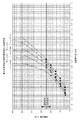
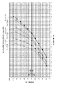
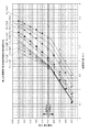
ここで、図17は、最大許容荷重が500kNの支承装置における鉛直変位量に対する鉛直荷重の特性を示し、図18は、最大許容荷重が1000kNの支承装置における鉛直変位量に対する鉛直荷重の特性を示し、図19は、最大許容荷重が3000kNの支承装置における鉛直変位量に対する鉛直荷重の特性を示し、図20は、最大許容荷重が10000kNの支承装置における鉛直変位量に対する鉛直荷重の特性を示している。   Here, FIG. 17 shows the characteristic of the vertical load with respect to the vertical displacement amount in the bearing device with the maximum allowable load of 500 kN, and FIG. 18 shows the characteristic of the vertical load with respect to the vertical displacement amount in the bearing device with the maximum allowable load of 1000 kN. FIG. 19 shows the characteristic of the vertical load with respect to the vertical displacement amount in the bearing device having the maximum allowable load of 3000 kN, and FIG. 20 shows the characteristic of the vertical load with respect to the vertical displacement amount in the bearing device having the maximum allowable load of 10,000 kN. .

図17では、最大許容荷重が500kNの支承装置においては、鉛直荷重が250kNより小さいときを、低荷重域と定義し、250kNより大きいときを高荷重域と定義している。また、図18では、最大許容荷重が1000kNの支承装置においては、鉛直荷重が500kNより小さいときを、低荷重域と定義し、500kNより大きいときを高荷重域と定義している。更に、図19では、最大許容荷重が3000kNの支承装置においては、鉛直荷重が1500kNより小さいときを、低荷重域と定義し、1500kNより大きいときを高荷重域と定義している。更に、図20では、最大許容荷重が10000kNの支承装置においては、鉛直荷重が5000kNより小さいときを、低荷重域と定義し、5000kNより大きいときを高荷重域と定義している。そして、図17−図20の各図のサンプルについて、低荷重域の近似直線と高荷重域の近似直線を最小二乗法を用いて作成し、各サンプルの低荷重域での一次勾配(傾き)と高荷重域での二次勾配(傾き)を算出した。   In FIG. 17, in a bearing device having a maximum allowable load of 500 kN, a case where the vertical load is smaller than 250 kN is defined as a low load region, and a case where the vertical load is larger than 250 kN is defined as a high load region. In FIG. 18, in a bearing device with a maximum allowable load of 1000 kN, a case where the vertical load is smaller than 500 kN is defined as a low load region, and a case where the vertical load is larger than 500 kN is defined as a high load region. Further, in FIG. 19, in the bearing device having a maximum allowable load of 3000 kN, a case where the vertical load is smaller than 1500 kN is defined as a low load region, and a case where the vertical load is larger than 1500 kN is defined as a high load region. Further, in FIG. 20, in the bearing device having the maximum allowable load of 10,000 kN, a case where the vertical load is smaller than 5000 kN is defined as a low load region, and a case where the vertical load is larger than 5000 kN is defined as a high load region. Then, for the samples shown in FIGS. 17 to 20, an approximate straight line in the low load region and an approximate straight line in the high load region are created using the least square method, and the primary gradient (slope) in the low load region of each sample is created. The secondary gradient (slope) in the high load range was calculated.

上述したように、本発明の支承装置では、弾性体13の外周面と拘束体16の拘束面16aとの間に隙間を設定することによって、荷重入力の初期や低荷重の入力時、鉛直荷重に対する鉛直可撓変位を可能としながら入力の高荷重化に伴って、徐々に鉛直変位量の増加量が小さくなって弾性率が高くなり、大きな荷重の入力に対しては密閉ゴム支承のように挙動して、小さな支承面積にして高荷重支持を実現するようにし、また、低荷重から高荷重の入力に亘って鉛直面内における回転力の作用時、弾性体13が拘束体16によって部分的に支持されながらも弾性体13と拘束体16との間の隙間により弾性体13が変形し、弾性体への極端な負荷なく、良好な回転追従性を実現するようにしている。すなわち、この支承装置では、一次勾配の低荷重の載荷では鉛直撓みがあるため弾性支承装置に属する扱いとすることができ、更に、弾性体13が急勾配の範囲(二次勾配)の領域において撓み量を所定量以内に抑えることで、車両通過時の振動や騒音を低減することが出来る。   As described above, in the support device of the present invention, by setting a gap between the outer peripheral surface of the elastic body 13 and the restraining surface 16a of the restraining body 16, the vertical load is applied at the initial stage of load input or when a low load is input. With the increase in input load while allowing vertical flexible displacement, the increase in vertical displacement gradually decreases and the elastic modulus increases, and a large load input is like a sealed rubber bearing. It behaves so as to realize a high load support with a small bearing area, and the elastic body 13 is partially supported by the restraint body 16 when a rotational force acts in the vertical plane from a low load to a high load input. The elastic body 13 is deformed by the gap between the elastic body 13 and the restraining body 16 while being supported by the elastic body 13 so as to realize good rotation follow-up performance without an extreme load on the elastic body. In other words, this bearing device can be treated as belonging to the elastic bearing device because of the vertical deflection when the primary gradient is loaded with a low load, and further, the elastic body 13 is in a region of a steep slope (secondary gradient). By suppressing the amount of deflection within a predetermined amount, vibration and noise when passing through the vehicle can be reduced.

本発明の支承装置では、このような作用効果を実現するため、低荷重域での一次勾配(傾き)に対する高荷重域での二次勾配(傾き)の勾配倍率が1.43−3.72の範囲となるようにしている。道路橋支承便覧(平成16年4月:社団法人日本道路協会)には、段差の照査上、圧縮変位量(段差)の許容値が1mm以内とされている。即ち、支承装置が上部構造物1と下部構造物2との間に設置され、死荷重を支持している状態から活荷重による撓み量を1mm以内に抑える必要がある。本発明では、低荷重域での一次勾配(傾き)に対する高荷重域での二次勾配(傾き)の勾配倍率を1.43−3.72の範囲とすることで、死荷重を支持している状態から活荷重による撓み量を1mm以内に抑え、車両通過時の振動や騒音を低減するようにしている。   In the bearing device of the present invention, in order to realize such an effect, the gradient magnification of the secondary gradient (inclination) in the high load region with respect to the primary gradient (inclination) in the low load region is 1.43-3.72. To be in the range. In the road bridge support manual (April 2004: Japan Road Association), the allowable value of the amount of compressive displacement (step) is set to 1 mm or less for checking the step. That is, it is necessary to suppress the deflection amount due to the live load within 1 mm from the state in which the support device is installed between the upper structure 1 and the lower structure 2 and supports the dead load. In the present invention, the dead load is supported by setting the gradient magnification of the secondary gradient (inclination) in the high load region to the primary gradient (inclination) in the low load region in the range of 1.43-3.72. The amount of deflection due to a live load is kept within 1 mm from the present state, and vibration and noise when passing through the vehicle are reduced.

[10−1.最大許容荷重が500kNの支承装置について]
図17は、最大許容荷重が500kNの支承装置10における鉛直荷重と鉛直撓み量の関係を示している。縦軸は、鉛直荷重[kN]を示し、横軸は、鉛直撓み量[mm]を示している。図17によれば、サンプル1−5の何れも、低荷重域、高荷重域の両方で、鉛直荷重が大きくなるに連れて鉛直変位量も大きくなり、低荷重域の一次勾配より高荷重域の二次勾配の方が勾配が急なものになっている。一般に、最大許容荷重が500kNの支承装置10においては、死荷重が300−350kNに設定され、活荷重が200−150kNに設定される。サンプル1−5では、低荷重域での一次勾配(傾き)に対する高荷重域での二次勾配(傾き)の勾配倍率(二次勾配/一次勾配)が1.65−3.37の範囲となっているので、活荷重域における鉛直変位量が1mm以内となり、車両通過時の振動や騒音を低減することが出来る。例えば、最も勾配の緩やかなサンプル5を例に見ても、鉛直荷重(死荷重)が約300kNのとき、鉛直変位量が約1.04mmであり、約500kNのとき、鉛直変位量が約1.34mmであり、撓み量の差が約0.3mmである。したがって、活荷重域における鉛直変位量を1mm以内に抑えることを実現することが出来る。
[10-1. Bearing device with a maximum allowable load of 500kN]
FIG. 17 shows the relationship between the vertical load and the amount of vertical deflection in the bearing device 10 having a maximum allowable load of 500 kN. The vertical axis represents the vertical load [kN], and the horizontal axis represents the vertical deflection amount [mm]. According to FIG. 17, in any of the samples 1-5, the vertical displacement increases as the vertical load increases in both the low load region and the high load region, and the higher load region than the primary gradient in the low load region. The quadratic gradient is steeper. Generally, in the bearing device 10 having a maximum allowable load of 500 kN, the dead load is set to 300-350 kN and the live load is set to 200-150 kN. In Sample 1-5, the gradient magnification (secondary gradient / primary gradient) of the secondary gradient (slope) in the high load region to the primary gradient (slope) in the low load region is 1.65 to 3.37. Therefore, the amount of vertical displacement in the live load region is within 1 mm, and vibration and noise when passing through the vehicle can be reduced. For example, even when the sample 5 having the gentlest gradient is taken as an example, when the vertical load (dead load) is about 300 kN, the vertical displacement is about 1.04 mm, and when the vertical load is about 500 kN, the vertical displacement is about 1 .34 mm, and the difference in deflection is about 0.3 mm. Therefore, it is possible to realize the vertical displacement amount in the live load region within 1 mm.

なお、上記道路橋支承便覧によれば、支承装置10について、回転撓みの照査上、1/150rad程度撓むことが出来ることが望ましいとされている。回転撓みの照査上において撓み量が足りないと、金属支承の扱いとなってしまい問題が生じる。即ち、最大許容荷重が500kNの支承装置10においては、撓み量δ=有効直径÷2÷150の式より、撓み量が0.53mm以上有ることが必要である。サンプル1−5の何れも、死荷重(例えば死荷重が300−350kN)が加わった際、撓み量が0.53mm以上にすることが出来、上記道路橋支承便覧の条件も満たすことが出来る。なお、ここで言う有効直径は、弾性体13の外周端部(面圧を受けない部分)を考慮して、設定直径より若干(直径で10mm以下程度)小さめの寸法としている。   In addition, according to the above-mentioned road bridge support manual, it is desirable that the support device 10 be able to bend about 1/150 rad in view of the rotational deflection. If the amount of deflection is insufficient on the check of rotational deflection, it will be handled as a metal bearing, causing a problem. That is, in the bearing device 10 having a maximum allowable load of 500 kN, the amount of deflection needs to be 0.53 mm or more from the equation of the amount of deflection δ = effective diameter ÷ 2 ÷ 150. In any of the samples 1-5, when a dead load (for example, a dead load of 300-350 kN) is applied, the amount of deflection can be 0.53 mm or more, and the conditions for the above-mentioned road bridge support manual can be satisfied. Note that the effective diameter referred to here is a dimension slightly smaller than the set diameter (about 10 mm or less in diameter) in consideration of the outer peripheral end portion (the portion not subjected to the surface pressure) of the elastic body 13.

以上のように、最大許容荷重が500kNの支承装置10(サンプル1−5)では、勾配倍率を1.43−3.72の範囲、好ましくは1.65−3.37の範囲にすることで、荷重が載荷された際の変位量を1mm以内の段差に抑えることが出来、車両通過時の振動や騒音を低減することが出来る。また、サンプル1−5の何れも、少なくとも死荷重(例えば300−350kN)が加わった際に、撓み量を0.53mm以上にすることが出来、上記道路橋支承便覧の条件も満たすことが出来、金属支承装置の扱いではなく、弾性支承装置に属する扱いに出来る。   As described above, in the bearing device 10 (sample 1-5) having a maximum allowable load of 500 kN, the gradient magnification is set to a range of 1.43-3.72, preferably 1.65 to 3.37. The amount of displacement when a load is loaded can be suppressed to a level difference of 1 mm or less, and vibration and noise when passing through the vehicle can be reduced. In addition, in any of the samples 1-5, when at least a dead load (for example, 300-350 kN) is applied, the deflection amount can be 0.53 mm or more, and the conditions for the above-mentioned road bridge support manual can be satisfied. It can be handled as belonging to an elastic bearing device, not a metal bearing device.

[10−2.最大許容荷重が1000kNの支承装置について]
図18は、最大許容荷重が1000kNの支承装置10における鉛直荷重と鉛直撓み量の関係を示している。縦軸は、鉛直荷重[kN]を示し、横軸は、鉛直撓み量[mm]を示している。図18によれば、サンプル6−11の何れも、低荷重域、高荷重域の両方で、鉛直荷重が大きくなるに連れて鉛直変位量も大きくなり、低荷重域の一次勾配より高荷重域の二次勾配の方が勾配が急なものになっている。一般に、最大許容荷重が1000kNの支承装置10においては、死荷重が600−700kNに設定され、活荷重が400−300kNに設定される。サンプル6−11では、低荷重域での一次勾配(傾き)に対する高荷重域での二次勾配(傾き)の勾配倍率(二次勾配/一次勾配)が1.73−3.62の範囲となっているので、活荷重域における鉛直変位量が1mm以内となり、車両通過時の振動や騒音を低減することが出来る。例えば、最も勾配の緩やかなサンプル11を例に見ても、鉛直荷重が約600kNのとき、鉛直変位量が約1.28mmであり、約1000kNのとき、鉛直変位量が約1.62mmであり、撓み量の差が約0.34mmである。したがって、活荷重域における鉛直変位量を1mm以内に抑えることを実現することが出来る。
[10-2. Bearing device with a maximum allowable load of 1000kN]
FIG. 18 shows the relationship between the vertical load and the vertical deflection amount in the bearing device 10 having a maximum allowable load of 1000 kN. The vertical axis represents the vertical load [kN], and the horizontal axis represents the vertical deflection amount [mm]. According to FIG. 18, in any of the samples 6-11, the vertical displacement amount increases as the vertical load increases in both the low load region and the high load region, which is higher than the primary gradient in the low load region. The quadratic gradient is steeper. Generally, in the bearing device 10 having a maximum allowable load of 1000 kN, the dead load is set to 600-700 kN and the live load is set to 400-300 kN. In Sample 6-11, the gradient factor (secondary gradient / primary gradient) of the secondary gradient (slope) in the high load region with respect to the primary gradient (slope) in the low load region is in the range of 1.73-3.62. Therefore, the amount of vertical displacement in the live load region is within 1 mm, and vibration and noise when passing through the vehicle can be reduced. For example, in the sample 11 having the gentlest gradient, the vertical displacement is about 1.28 mm when the vertical load is about 600 kN, and the vertical displacement is about 1.62 mm when the vertical load is about 1000 kN. The difference in deflection amount is about 0.34 mm. Therefore, it is possible to realize the vertical displacement amount in the live load region within 1 mm.

なお、上記道路橋支承便覧によれば、上述のように、金属支承の扱いとならないように、回転撓みの照査上、1/150rad程度撓むことが必要であり、撓み量が0.75mm以上有ることが必要である。サンプル6−11の何れも、死荷重(例えば死荷重が600−700kN)が加わった際、撓み量が0.75mm以上にすることが出来、上記道路橋支承便覧の条件も満たすことが出来る。   In addition, according to the above-mentioned road bridge support manual, as described above, it is necessary to bend about 1/150 rad on the basis of the rotational deflection so that it is not handled as a metal bearing, and the deflection amount is 0.75 mm or more. It is necessary to be. In any of the samples 6-11, when a dead load (for example, a dead load is 600 to 700 kN) is applied, the amount of deflection can be set to 0.75 mm or more, and the conditions for the road bridge support manual can be satisfied.

以上のように、最大許容荷重が1000kNの支承装置10(サンプル6−11)では、勾配倍率を1.43−3.72、好ましくは1.73−3.62の範囲の範囲にすることで、荷重が載荷された際の変位量を1mm以内の段差に抑えることが出来、車両通過時の振動や騒音を低減することが出来る。また、サンプル6−11の何れも、少なくとも死荷重(例えば600−700kN)が加わった際、撓み量を0.75mm以上にすることが出来、上記道路橋支承便覧の条件も満たすことが出来、金属支承装置の扱いではなく、弾性支承装置に属する扱いに出来る。   As described above, in the bearing device 10 (sample 6-11) having a maximum allowable load of 1000 kN, the gradient magnification is set to a range of 1.43-3.72, preferably 1.73-3.62. The amount of displacement when a load is loaded can be suppressed to a level difference of 1 mm or less, and vibration and noise when passing through the vehicle can be reduced. In addition, in any of the samples 6-11, when at least a dead load (for example, 600-700 kN) is applied, the amount of deflection can be set to 0.75 mm or more, and the conditions for the road bridge support manual can be satisfied. It can be handled as belonging to an elastic bearing device, not a metal bearing device.

[10−3.最大許容荷重が3000kNの支承装置について]
図19は、最大許容荷重が3000kNの支承装置10における鉛直荷重と鉛直撓み量の関係を示している。縦軸は、鉛直荷重[kN]を示し、横軸は、鉛直撓み量[mm]を示している。図19によれば、サンプル12−21の何れも、低荷重域、高荷重域の両方で、鉛直荷重が大きくなるに連れて鉛直変位量も大きくなり、低荷重域の一次勾配より高荷重域の二次勾配の方が勾配が急なものになっている。一般に、最大許容荷重が3000kNの支承装置10においては、死荷重が1800−2100kNに設定され、活荷重が1200−900kNに設定される。サンプル12−21では、低荷重域での一次勾配(傾き)に対する高荷重域での二次勾配(傾き)の勾配倍率(二次勾配/一次勾配)が1.43−3.72の範囲となっているので、活荷重域における鉛直変位量が1mm以内となり、車両通過時の振動や騒音を低減することが出来る。例えば、最も勾配の緩やかなサンプル21を例に見ても、鉛直荷重が約1800kNのとき、鉛直変位量が約2.15mmであり、約3000kNのとき、鉛直変位量が約2.7mmであり、撓み量の差が約0.55mmである。したがって、活荷重域における鉛直変位量を1mm以内に抑えることを実現することが出来る。
[10-3. Bearing device with a maximum allowable load of 3000kN]
FIG. 19 shows the relationship between the vertical load and the vertical deflection amount in the bearing device 10 having a maximum allowable load of 3000 kN. The vertical axis represents the vertical load [kN], and the horizontal axis represents the vertical deflection amount [mm]. According to FIG. 19, in any of the samples 12-21, the vertical displacement increases as the vertical load increases in both the low load region and the high load region, and the higher load region than the primary gradient in the low load region. The quadratic gradient is steeper. Generally, in the bearing device 10 having a maximum allowable load of 3000 kN, the dead load is set to 1800-2100 kN and the live load is set to 1200-900 kN. In Sample 12-21, the gradient ratio (secondary gradient / primary gradient) of the secondary gradient (gradient) in the high load region to the primary gradient (gradient) in the low load region is in the range of 1.43-3.72. Therefore, the amount of vertical displacement in the live load region is within 1 mm, and vibration and noise when passing through the vehicle can be reduced. For example, even when the sample 21 having the gentlest slope is taken as an example, when the vertical load is about 1800 kN, the vertical displacement is about 2.15 mm, and when the vertical load is about 3000 kN, the vertical displacement is about 2.7 mm. The difference in deflection amount is about 0.55 mm. Therefore, it is possible to realize the vertical displacement amount in the live load region within 1 mm.

なお、上記道路橋支承便覧によれば、上述のように、金属支承の扱いとならないように、回転撓みの照査上、1/150rad程度撓むことが必要であり、撓み量が1.3mm以上有ることが必要である。サンプル12を除くサンプル13−21は、少なくとも死荷重(例えば1800−2100kN)が加わった際、撓み量が1.30mm以上にすることが出来、上記道路橋支承便覧の条件も満たすことが出来る。   In addition, according to the above-mentioned road bridge support manual, as described above, it is necessary to bend about 1/150 rad on the basis of the rotational deflection so that it is not handled as a metal bearing, and the deflection amount is 1.3 mm or more. It is necessary to be. The sample 13-21 except the sample 12 can have a deflection amount of 1.30 mm or more when a dead load (for example, 1800-2100 kN) is applied, and can also satisfy the conditions of the road bridge support manual.

以上のように、最大許容荷重が3000kNの支承装置10(サンプル12−21)では、勾配倍率を1.43−3.72の範囲にすることで、荷重が載荷された際の変位量を1mm以内の段差に抑えることが出来、車両通過時の振動や騒音を低減することが出来る。また、サンプル12を除くサンプル13−21は、少なくとも死荷重(例えば1800−2100kN)が加わった際、撓み量を1.30mm以上にすることが出来、上記道路橋支承便覧の条件も満たすことが出来、金属支承装置の扱いではなく、弾性支承装置に属する扱いに出来る。   As described above, in the bearing device 10 (sample 12-21) having a maximum allowable load of 3000 kN, the displacement amount when the load is loaded is 1 mm by setting the gradient magnification in the range of 1.43-3.72. It is possible to suppress the level difference within the range, and vibration and noise when passing through the vehicle can be reduced. In addition, the sample 13-21 except the sample 12 can have a deflection amount of 1.30 mm or more when at least a dead load (for example, 1800-2100 kN) is applied, and can satisfy the conditions of the road bridge support manual. Yes, it can be handled as belonging to an elastic bearing device, not a metal bearing device.

[10−4.最大許容荷重が10000kNの支承装置について]
図20は、最大許容荷重が10000kNの支承装置10における鉛直荷重と鉛直撓み量の関係を示している。縦軸は、鉛直荷重[kN]を示し、横軸は、鉛直撓み量[mm]を示している。図20によれば、サンプル22−31の何れも、低荷重域、高荷重域の両方で、鉛直荷重が大きくなるに連れて鉛直変位量も大きくなり、低荷重域の一次勾配より高荷重域の二次勾配の方が勾配が急なものになっている。一般に、最大許容荷重が10000kNの支承装置10においては、死荷重が6000−7000kNに設定され、活荷重が4000−3000kNに設定される。サンプル22−31では、低荷重域での一次勾配(傾き)に対する高荷重域での二次勾配(傾き)の勾配倍率(二次勾配/一次勾配)が1.74−2.83の範囲となっているので、活荷重域における鉛直変位量が1mm以内となり、車両通過時の振動や騒音を低減することが出来る。例えば、サンプル31を例に見ても、鉛直荷重が約6000kNのとき、鉛直変位量が約3.0mmであり、約10000kNのとき、鉛直変位量が約3.4mmであり、撓み量の差が約0.4mmである。したがって、活荷重域における鉛直変位量を1mm以内に抑えることを実現することが出来る。
[10-4. Bearing device with a maximum allowable load of 10,000 kN]
FIG. 20 shows the relationship between the vertical load and the amount of vertical deflection in the bearing device 10 having a maximum allowable load of 10,000 kN. The vertical axis represents the vertical load [kN], and the horizontal axis represents the vertical deflection amount [mm]. According to FIG. 20, in any of samples 22-31, the vertical displacement increases as the vertical load increases in both the low load region and the high load region, which is higher than the primary gradient in the low load region. The quadratic gradient is steeper. Generally, in the bearing device 10 having a maximum allowable load of 10,000 kN, the dead load is set to 6000-7000 kN and the live load is set to 4000-3000 kN. In Sample 22-31, the gradient magnification (secondary gradient / primary gradient) of the secondary gradient (slope) in the high load region with respect to the primary gradient (slope) in the low load region is in the range of 1.74-2.83. Therefore, the amount of vertical displacement in the live load region is within 1 mm, and vibration and noise when passing through the vehicle can be reduced. For example, when the sample 31 is taken as an example, the vertical displacement is about 3.0 mm when the vertical load is about 6000 kN, and the vertical displacement is about 3.4 mm when the vertical load is about 10000 kN. Is about 0.4 mm. Therefore, it is possible to realize the vertical displacement amount in the live load region within 1 mm.

なお、上記道路橋支承便覧によれば、上述のように、金属支承の扱いとならないように、回転撓みの照査上、1/150rad程度撓むことが必要であり、撓み量が2.4mm以上有ることが必要である。サンプル22を除くサンプル23−31は、少なくとも死荷重(例えば6000−7000kN)が加わった際、撓み量が2.4mm以上にすることが出来、上記道路橋支承便覧の条件も満たすことが出来る。   In addition, according to the above-mentioned road bridge support manual, as described above, it is necessary to bend about 1/150 rad on the basis of the rotational deflection so that it is not handled as a metal bearing, and the deflection amount is 2.4 mm or more. It is necessary to be. The sample 23-31 except the sample 22 can have a deflection amount of 2.4 mm or more when at least a dead load (for example, 6000-7000 kN) is applied, and can also satisfy the conditions of the road bridge support manual.

以上のように、最大許容荷重が10000kNの支承装置10(サンプル22−31)では、勾配倍率を1.43−3.72、好ましくは1.74−2.83の範囲の範囲にすることで、荷重が載荷された際の変位量を1mm以内の段差に抑えることが出来、車両通過時の振動や騒音を低減することが出来る。また、サンプル22を除くサンプル23−31は、少なくとも死荷重(例えば6000−7000kN)が加わった際、撓み量を2.4mm以上にすることが出来、上記道路橋支承便覧の条件も満たすことが出来、金属支承装置の扱いではなく、弾性支承装置に属する扱いに出来る。   As described above, in the bearing device 10 (sample 22-31) having a maximum allowable load of 10,000 kN, the gradient magnification is set to a range of 1.43-3.72, preferably 1.74-2.83. The amount of displacement when a load is loaded can be suppressed to a level difference of 1 mm or less, and vibration and noise when passing through the vehicle can be reduced. In addition, the sample 23-31 excluding the sample 22 can have a deflection amount of 2.4 mm or more when at least a dead load (for example, 6000-7000 kN) is applied, and can also satisfy the conditions of the road bridge support manual. Yes, it can be handled as belonging to an elastic bearing device, not a metal bearing device.

[11.その他の変形例]
上述の説明では、本発明の支承装置として橋梁用支承装置について説明したが、本発明は橋梁用支承装置に限定されることはなく、各種の構造物の制震、免震用の支承装置として採用することが出来る。
[11. Other variations]
In the above description, the bridge support device has been described as the support device of the present invention. However, the present invention is not limited to the bridge support device, but as a support device for vibration control and seismic isolation of various structures. It can be adopted.

1 上部構造物、2 下部構造物、3 上部プレート、4 摺滑部材、5 下部プレート、6 摺滑部材、10 支承装置、11 上沓、12 下沓、13 弾性体、13 凸部13(13a,13b,13c) 弾性体、14 凸部、15 凹部、16 拘束体、16b,16c 固定手段、16d ポット部、17 貫通孔、17a 上揚防止片、18 芯材、19 大径部、21 挿通孔、22 ネジ穴、23 積層型弾性体、23a 補強板、23b 弾性層、23c 環状突出部、24 凸部、25 凹部、25,27a 突出部、27b 凹部,28a 空隙部、30 支承装置、31 芯材、32 上揚防止片、33 大径部、34 ネジ穴、40 支承装置、41 芯材、41a 位置決め凸部、41b 位置決め凹部、42 上揚防止片、43 大径部、43a ネジ穴、44 ネジ部、45a 挿通孔、45b 固定ボルト、45c 固定孔、45d 凹部、61 凸部、62 凹部 DESCRIPTION OF SYMBOLS 1 Upper structure, 2 Lower structure, 3 Upper plate, 4 Sliding member, 5 Lower plate, 6 Sliding member, 10 Support apparatus, 11 Upper collar, 12 Lower collar, 13 Elastic body, 13 Convex part 13 (13a , 13b, 13c) Elastic body, 14 convex part, 15 concave part, 16 restraint body, 16b, 16c fixing means, 16d pot part, 17 through hole, 17a lifting prevention piece, 18 core material, 19 large diameter part, 21 insertion hole , 22 Screw hole, 23 Laminated elastic body, 23a Reinforcement plate, 23b Elastic layer, 23c Annular projecting part, 24 Convex part, 25 Concave part, 25, 27a Protruding part, 27b Concave part, 28a Cavity part, 30 Bearing device, 31 core Material, 32 Lifting prevention piece, 33 Large diameter part, 34 Screw hole, 40 Bearing device, 41 Core material, 41a Positioning convex part, 41b Positioning concave part, 42 Lifting prevention piece, 43 Large diameter part 43a screw hole, 44 the threaded portion, 45a through hole, 45b fixing bolt, 45 c fixing hole, 45d recess 61 protrusion, 62 recess

Claims (16)

第一剛性体と、第二剛性体と、前記第一剛性体と前記第二剛性体との間に配設される弾性体と、前記弾性体を囲繞する拘束体とを備え、
前記拘束体と前記弾性体との間に、隙間が設けられ、
鉛直変位量に対する鉛直荷重の特性が低荷重域の一次勾配と高荷重域の二次勾配とを有し、
前記二次勾配の近似直線の傾きが前記一次勾配の近似直線の傾きより大きく、
所定以上入力されると、前記拘束体は、変形した前記弾性体が当接及び/又は圧接され、前記弾性体の変形を拘束することを特徴とする支承装置。
A first rigid body, a second rigid body, an elastic body disposed between the first rigid body and the second rigid body, and a restraining body surrounding the elastic body,
A gap is provided between the restraining body and the elastic body,
The characteristic of the vertical load with respect to the vertical displacement amount has a primary gradient in the low load region and a secondary gradient in the high load region,
The gradient of the approximate line of the secondary slope is rather greater than the slope of the approximate line of the primary gradient,
The support device according to claim 1, wherein when the input is greater than or equal to a predetermined amount, the deformed elastic body is brought into contact with and / or pressed against the deformed elastic body to restrain deformation of the elastic body .
前記一次勾配に対する二次勾配の勾配倍率は、1.43以上であることを特徴とする請求項1に記載の支承装置。   The bearing device according to claim 1, wherein a gradient magnification of the secondary gradient with respect to the primary gradient is 1.43 or more. 前記一次勾配に対する二次勾配の勾配倍率は、3.72以下であることを特徴とする請求項2に記載の支承装置。   The bearing device according to claim 2, wherein a gradient magnification of the secondary gradient with respect to the primary gradient is 3.72 or less. 最大許容荷重が500kNの場合、前記一次勾配に対する二次勾配の勾配倍率が1.65−3.37の範囲にあることを特徴とする請求項3に記載の支承装置。   4. The bearing device according to claim 3, wherein when the maximum allowable load is 500 kN, the gradient magnification of the secondary gradient with respect to the primary gradient is in the range of 1.65 to 3.37. 最大許容荷重が1000kNの場合、前記一次勾配に対する二次勾配の勾配倍率が1.73−3.62の範囲にあることを特徴とする請求項3に記載の支承装置。   4. The bearing device according to claim 3, wherein when the maximum allowable load is 1000 kN, a gradient factor of the secondary gradient with respect to the primary gradient is in a range of 1.73 to 3.62. 最大許容荷重が3000kNの場合、前記一次勾配に対する二次勾配の勾配倍率が1.43−3.72の範囲にあることを特徴とする請求項3に記載の支承装置。   4. The bearing device according to claim 3, wherein when the maximum allowable load is 3000 kN, the gradient factor of the secondary gradient with respect to the primary gradient is in the range of 1.43-3.72. 最大許容荷重が10000kNの場合、前記一次勾配に対する二次勾配の勾配倍率が1.74−2.83の範囲にあることを特徴とする請求項3に記載の支承装置。   4. The bearing device according to claim 3, wherein when the maximum allowable load is 10,000 kN, a gradient factor of the secondary gradient with respect to the primary gradient is in a range of 1.74-2.83. 前記弾性体は、前記第一剛性体と前記第二剛性体と前記拘束体とによって囲繞されて略密閉状態とされ、
前記弾性体への荷重の増大に伴って、より高度な密閉状態へと変化することを特徴とする請求項1−の何れかに記載の支承装置。
The elastic body is surrounded by the first rigid body, the second rigid body, and the restraining body to be in a substantially sealed state,
The bearing device according to any one of claims 1 to 7 , wherein the bearing device changes to a higher sealed state as the load on the elastic body increases.
前記弾性体は、弾性層と補強板とが積層された積層構造で構成されていることを特徴とする請求項1−の何れかに記載の支承装置。 The elastic body bearing apparatus according to any one of claims 1 8, characterized in that the elastic layer reinforcing plate is constituted by a laminated structure that is laminated. 前記弾性体の側面又は前記拘束体の拘束面には、前記補強板の位置又は前記補強板の間の位置の一方に凸部又は凹部を形成し、他方に凹部又は凸部を形成することを特徴とする請求項に記載の支承装置。 A convex portion or a concave portion is formed on one of the position of the reinforcing plate or the position between the reinforcing plates on the side surface of the elastic body or the restraining surface of the restricting body, and the concave portion or the convex portion is formed on the other. The supporting device according to claim 9 . 前記弾性体は、単層の弾性層で構成されていることを特徴とする請求項1−の何れかに記載の支承装置。 The elastic body bearing apparatus according to any one of claims 1 8, characterized by being composed of an elastic layer of a single layer. 前記弾性体の側面又は前記拘束体の拘束面には、凸部及び/又は凹部が形成されることを特徴とする請求項11に記載の支承装置。 The support device according to claim 11 , wherein a convex portion and / or a concave portion is formed on a side surface of the elastic body or a constraining surface of the constraining body. 前記凸部又は凹部は、前記弾性体の側面又は前記拘束体の拘束面の周回り方向に連続及び/又は断続的に形成されていることを特徴とする請求項10又は12に記載の支承装置。 The support device according to claim 10 or 12 , wherein the convex portion or the concave portion is formed continuously and / or intermittently in a circumferential direction of a side surface of the elastic body or a constraining surface of the constraining body. . 前記弾性体の前記凸部が前記拘束体の拘束面に当接することを特徴とする請求項101213の何れかに記載の支承装置。 Bearing apparatus according to claim 10, 12, 13, wherein the convex portion of the elastic member abuts against the restraining surface of the restraining member. 前記拘束体は、前記第一剛性体と一体的に設けられていることを特徴とする請求項1−14の何れかに記載の支承装置。 The restraining body, bearing device according to any one of claims 1- 14, characterized in that provided the integrally with the first rigid member. 前記拘束体は、前記第二剛性体と一体的に設けられていることを特徴とする請求項1−14の何れかに記載の支承装置。 The restraining body, bearing device according to any one of claims 1- 14, characterized in that provided the integrally with the second rigid body.
JP2011242733A 2011-09-08 2011-11-04 Bearing device Active JP5330486B2 (en)

Priority Applications (2)

Application Number Priority Date Filing Date Title
JP2011242733A JP5330486B2 (en) 2011-11-04 2011-11-04 Bearing device
PCT/JP2012/073098 WO2013035879A1 (en) 2011-09-08 2012-09-10 Support device

Applications Claiming Priority (1)

Application Number Priority Date Filing Date Title
JP2011242733A JP5330486B2 (en) 2011-11-04 2011-11-04 Bearing device

Publications (3)

Publication Number Publication Date
JP2013096195A JP2013096195A (en) 2013-05-20
JP2013096195A5 JP2013096195A5 (en) 2013-07-04
JP5330486B2 true JP5330486B2 (en) 2013-10-30

Family

ID=48618447

Family Applications (1)

Application Number Title Priority Date Filing Date
JP2011242733A Active JP5330486B2 (en) 2011-09-08 2011-11-04 Bearing device

Country Status (1)

Country Link
JP (1) JP5330486B2 (en)

Families Citing this family (2)

* Cited by examiner, † Cited by third party
Publication number Priority date Publication date Assignee Title
JP6062907B2 (en) * 2014-10-29 2017-01-18 東京ファブリック工業株式会社 Rubber bearing body and rubber bearing apparatus provided with the rubber bearing body
AT524177B1 (en) * 2020-09-14 2022-05-15 Engel Austria Gmbh Plasticizing unit for a molding machine and molding machine with a corresponding plasticizing unit

Family Cites Families (1)

* Cited by examiner, † Cited by third party
Publication number Priority date Publication date Assignee Title
JP3018291B2 (en) * 1997-11-21 2000-03-13 株式会社カイモン Sliding elastic bearing device for structures

Also Published As

Publication number Publication date
JP2013096195A (en) 2013-05-20

Similar Documents

Publication Publication Date Title
JP5373274B2 (en) Anti-vibration structure
JP5330463B2 (en) Elastic body restraint degree variable structure
US20190120321A1 (en) Seismic isolation apparatus
JP5330486B2 (en) Bearing device
CA2907567A1 (en) Disc and spring isolation bearing
JP5390565B2 (en) Bearing device
JP5244220B2 (en) Bearing device
JP5330485B2 (en) Bearing device
JP5390574B2 (en) Bearing device
JP5690112B2 (en) Bearing device
JP5330472B2 (en) Elastic body restraint variable structure and bearing device
JP2018136000A (en) Seismic isolator
JP5186589B1 (en) Bearing device
JP2018071602A (en) Lower cushion rubber for upper support
JP5330475B2 (en) Bearing structure
JP6809951B2 (en) Connection vibration isolation device for seismic isolation bearings
JP2018132175A (en) Upper support
JP5390583B2 (en) Bearing structure
JP5703035B2 (en) Seismic isolation device
JP5702643B2 (en) Bearing device
JP5392685B2 (en) Isolator protection device and method of assembling the same
JP2015052354A (en) Vibration prevention support device
JP6030289B2 (en) Bearing device
WO2013008828A1 (en) Bearing device
JP5651429B2 (en) Bearing device

Legal Events

Date Code Title Description
A521 Request for written amendment filed

Free format text: JAPANESE INTERMEDIATE CODE: A523

Effective date: 20130516

A621 Written request for application examination

Free format text: JAPANESE INTERMEDIATE CODE: A621

Effective date: 20130516

A871 Explanation of circumstances concerning accelerated examination

Free format text: JAPANESE INTERMEDIATE CODE: A871

Effective date: 20130516

A975 Report on accelerated examination

Free format text: JAPANESE INTERMEDIATE CODE: A971005

Effective date: 20130604

TRDD Decision of grant or rejection written
A01 Written decision to grant a patent or to grant a registration (utility model)

Free format text: JAPANESE INTERMEDIATE CODE: A01

Effective date: 20130702

A61 First payment of annual fees (during grant procedure)

Free format text: JAPANESE INTERMEDIATE CODE: A61

Effective date: 20130725

R150 Certificate of patent or registration of utility model

Ref document number: 5330486

Country of ref document: JP

Free format text: JAPANESE INTERMEDIATE CODE: R150

Free format text: JAPANESE INTERMEDIATE CODE: R150

R250 Receipt of annual fees

Free format text: JAPANESE INTERMEDIATE CODE: R250

R250 Receipt of annual fees

Free format text: JAPANESE INTERMEDIATE CODE: R250

R250 Receipt of annual fees

Free format text: JAPANESE INTERMEDIATE CODE: R250

S531 Written request for registration of change of domicile

Free format text: JAPANESE INTERMEDIATE CODE: R313531

R250 Receipt of annual fees

Free format text: JAPANESE INTERMEDIATE CODE: R250

R350 Written notification of registration of transfer

Free format text: JAPANESE INTERMEDIATE CODE: R350