JP5330300B2 - Explosion simulation in finite element analysis - Google Patents
Explosion simulation in finite element analysis Download PDFInfo
- Publication number
- JP5330300B2 JP5330300B2 JP2010069823A JP2010069823A JP5330300B2 JP 5330300 B2 JP5330300 B2 JP 5330300B2 JP 2010069823 A JP2010069823 A JP 2010069823A JP 2010069823 A JP2010069823 A JP 2010069823A JP 5330300 B2 JP5330300 B2 JP 5330300B2
- Authority
- JP
- Japan
- Prior art keywords
- explosion
- fluid
- boundary
- group
- finite element
- Prior art date
- Legal status (The legal status is an assumption and is not a legal conclusion. Google has not performed a legal analysis and makes no representation as to the accuracy of the status listed.)
- Active
Links
- 238000004880 explosion Methods 0.000 title claims abstract description 121
- 238000004088 simulation Methods 0.000 title claims abstract description 32
- 238000004458 analytical method Methods 0.000 title claims abstract description 26
- 238000000034 method Methods 0.000 claims abstract description 38
- 239000012530 fluid Substances 0.000 claims abstract description 35
- 230000003993 interaction Effects 0.000 claims abstract description 24
- 239000007787 solid Substances 0.000 claims description 6
- 238000009499 grossing Methods 0.000 claims description 5
- 238000013507 mapping Methods 0.000 claims description 4
- 238000012360 testing method Methods 0.000 claims description 3
- 230000001052 transient effect Effects 0.000 claims 1
- 239000002356 single layer Substances 0.000 abstract description 2
- 238000004590 computer program Methods 0.000 description 12
- 238000004891 communication Methods 0.000 description 11
- 230000010354 integration Effects 0.000 description 11
- 239000002360 explosive Substances 0.000 description 7
- 238000010586 diagram Methods 0.000 description 6
- 230000035939 shock Effects 0.000 description 6
- 238000013459 approach Methods 0.000 description 5
- 239000010410 layer Substances 0.000 description 5
- 239000002245 particle Substances 0.000 description 5
- 230000008569 process Effects 0.000 description 5
- XLYOFNOQVPJJNP-UHFFFAOYSA-N water Substances O XLYOFNOQVPJJNP-UHFFFAOYSA-N 0.000 description 5
- 230000006399 behavior Effects 0.000 description 4
- 230000006870 function Effects 0.000 description 4
- 230000005540 biological transmission Effects 0.000 description 3
- 230000005484 gravity Effects 0.000 description 3
- 238000013461 design Methods 0.000 description 2
- 238000012986 modification Methods 0.000 description 2
- 230000004048 modification Effects 0.000 description 2
- 230000003287 optical effect Effects 0.000 description 2
- 229910000831 Steel Inorganic materials 0.000 description 1
- 230000001133 acceleration Effects 0.000 description 1
- 239000003570 air Substances 0.000 description 1
- 230000004075 alteration Effects 0.000 description 1
- 230000002238 attenuated effect Effects 0.000 description 1
- 238000004364 calculation method Methods 0.000 description 1
- 238000013016 damping Methods 0.000 description 1
- 238000005516 engineering process Methods 0.000 description 1
- 230000007613 environmental effect Effects 0.000 description 1
- 238000002474 experimental method Methods 0.000 description 1
- 239000011159 matrix material Substances 0.000 description 1
- 230000000704 physical effect Effects 0.000 description 1
- 238000010561 standard procedure Methods 0.000 description 1
- 239000010959 steel Substances 0.000 description 1
- 238000012916 structural analysis Methods 0.000 description 1
Images


Classifications
-
- G—PHYSICS
- G06—COMPUTING; CALCULATING OR COUNTING
- G06F—ELECTRIC DIGITAL DATA PROCESSING
- G06F30/00—Computer-aided design [CAD]
- G06F30/20—Design optimisation, verification or simulation
- G06F30/23—Design optimisation, verification or simulation using finite element methods [FEM] or finite difference methods [FDM]
-
- G—PHYSICS
- G06—COMPUTING; CALCULATING OR COUNTING
- G06F—ELECTRIC DIGITAL DATA PROCESSING
- G06F2111/00—Details relating to CAD techniques
- G06F2111/10—Numerical modelling
Landscapes
- Engineering & Computer Science (AREA)
- Physics & Mathematics (AREA)
- Theoretical Computer Science (AREA)
- Computer Hardware Design (AREA)
- Evolutionary Computation (AREA)
- Geometry (AREA)
- General Engineering & Computer Science (AREA)
- General Physics & Mathematics (AREA)
- Management, Administration, Business Operations System, And Electronic Commerce (AREA)
Abstract
Description
本発明は、概して、コンピュータ支援工学解析において用いられる方法、システムおよびソフトウェア製品に関し、特に有限要素解析法において爆発による流体−構造体相互作用をシミュレートする改良方法に関する。 The present invention relates generally to methods, systems, and software products used in computer-aided engineering analysis, and more particularly to an improved method for simulating fluid-structure interactions due to explosions in finite element analysis methods.
有限要素解析法(FEA)は、技術者や科学者が三次元非線形構造設計および解析など複雑なシステムを表す偏微分方程式の近似解を見つける数値的解法を用いる、コンピュータによって実現される方法である。FEAは、土木工学および航空工学において複雑な弾性および構造分析問題を解く必要性から生み出された方法である。コンピュータ技術の進歩により、FEAは、技術者と科学者が構造設計(例えば自動車、飛行機など)を改良する際に決定を行うことを支援する不可欠なツールとなった。時間領域における物理的な問題あるいはイベントを解く際にFEAを適用する場合、それを時間進行シミュレーションとしていう。一般に、時間進行シミュレーションは、多くのソリューションサイクルからなる。FEAの結果すなわち解(ソリューション)は、それぞれのソリューションサイクルにおいて、ある特定の時間におけるトータルシミュレーションのスナップショットとして、得られる。 Finite Element Analysis (FEA) is a computer-implemented method that uses a numerical solution where engineers and scientists find approximate solutions of partial differential equations representing complex systems such as three-dimensional nonlinear structural design and analysis. . FEA is a method created from the need to solve complex elasticity and structural analysis problems in civil engineering and aeronautical engineering. Advances in computer technology have made FEA an indispensable tool to help engineers and scientists make decisions when improving structural designs (eg, cars, airplanes, etc.). When FEA is applied when solving a physical problem or event in the time domain, it is referred to as time progress simulation. In general, time progression simulation consists of many solution cycles. The FEA result or solution (solution) is obtained as a snapshot of the total simulation at a specific time in each solution cycle.
FEAがポピュラーになっていくにつれ、FEAの使用は、より複雑な物理的な現象、例えば爆発による流体−構造体の相互作用をシミュレートするのにも適用され出した。流体および構造体の挙動をシミュレートするには、任意ラグランジュ‐オイラー(Arbitrary Lagrangian−Eulerian (ALE))有限要素法と呼ばれる方法がよく用いられる。 As FEA has become popular, the use of FEA has also been applied to simulate more complex physical phenomena, such as fluid-structure interactions due to explosions. A method called Arbitrary Lagrangian-Eulerian (ALE) finite element method is often used to simulate the behavior of fluids and structures.
そのようなシミュレーションに用いられる例示的なFEAモデル100を、図1に示す。FEAモデル100は、爆発の爆発源102と、構造体を表わす第1FEAメッシュ(白の五角形として示す)112と、周囲流体を表す第2FEAメッシュ114と、を備える。図の簡単化のため、モデル100を二次元で示している。一般には、三次元モデルが、そのようなシミュレーションにおいて用いられる。
An exemplary FEA
爆発波104は、爆発(つまり比較的小さく局所的な体積内にある大きなエネルギー量の放出)に起因する圧力および流れである。流れの範囲を、爆風が後に続く先頭の衝撃波として近似することができる。流体(あるいは第2メッシュ114)の中を進む爆発波104の物理的なシミュレート挙動を把握するには、非常に細かいFEAメッシュ(つまり小さい要素(エレメント))がFEAモデル100に必要とされる。図の簡単化のために、比較的粗いメッシュ114を図1に示している。
時間進行シミュレーションのそれぞれのソリューションサイクルにおける解を得るために、明示的時間積分法(explicit time integration scheme)が用いられる。明示的時間積分法における一つの要求は、ソリューションサイクル間の時間ステップすなわち時間インクリメントが、FEAモデルにおいて用いられる最も小さい寸法(例えば最小要素)およびFEAモデルの媒体(例えば、空気、水、鋼など)における音速によって制御され決定される臨界時間ステップ以下であることである。 An explicit time integration scheme is used to obtain a solution in each solution cycle of the time progression simulation. One requirement in the explicit time integration method is that the time step or time increment between solution cycles is the smallest dimension (eg, smallest element) used in the FEA model and the medium of the FEA model (eg, air, water, steel, etc.) Is below a critical time step controlled and determined by the speed of sound at.
爆発波の挙動を把握するために第2メッシュ114が非常に細かいことを要求されるので、爆発による流体−構造体相互作用をシミュレートするには非常に短い時間ステップが必要となる。その結果、非常に多数のソリューションサイクルが必要とされる。このため、最も最新で最高技術水準のコンピュータシステムを用いてさえ非常に長い演算時間がかかり、そのために、ユーザ(例えば技術者、科学者など)の生産性を低下させることになる。
Since the
したがって、従来技術のアプローチの上記問題、欠点および短所を回避する有限要素解析法における爆発の時間進行シミュレーションの改良方法が望まれよう。 Therefore, an improved method of time progression simulation of explosions in a finite element analysis method that avoids the above problems, disadvantages and disadvantages of prior art approaches would be desirable.
本発明において、時間進行有限要素解析法において爆発をシミュレートするシステムおよび方法を開示する。一の面では、方法は、爆発による流体−構造体相互作用をシミュレートする演算時間の低減によって、ユーザ(例えば技術者あるいは科学者)の生産性を向上するよう構成される。方法は、構造体と、周囲流体と、爆発の爆発源と、爆発源に面する流体の境界を表わすセグメントを含んでいる境界要素の単一層と、を有するFEAモデルの生成を備える。境界要素は、爆発源と構造体との間に位置するよう構成され、これにより、指定された1セットの境界条件でシミュレーションを実行することができる。境界条件は、爆発源の実験式(例えばフリートレンダー(Friedlander)方程式)から決定される圧力およびノードの速度を備える。 In the present invention, a system and method for simulating an explosion in a time progression finite element analysis method is disclosed. In one aspect, the method is configured to increase the productivity of a user (eg, a technician or scientist) by reducing the computation time that simulates fluid-structure interaction due to an explosion. The method comprises generating an FEA model having a structure, an ambient fluid, an explosion source of an explosion, and a single layer of boundary elements including segments representing the boundary of the fluid facing the explosion source. The boundary element is configured to be located between the explosion source and the structure so that the simulation can be performed with a specified set of boundary conditions. Boundary conditions comprise pressure and nodal velocity determined from explosive source empirical equations (e.g., Friedlander equations).
FEAモデルに含まれる境界要素の層により、爆発源とセグメントの間の流体を表わすFEAメッシュ(例えばALE有限要素)を必要としない。制限は、爆発源とセグメントとの間の流体が均質であるということである。爆発の特性は、爆発源の位置および質量と、指定時間と、によって表わされる。概して、FEAモデルは、爆発源の位置を指定することができるグローバル座標システムにおいて定義される。 The boundary element layer included in the FEA model does not require an FEA mesh (eg, an ALE finite element) representing the fluid between the explosion source and the segment. The limitation is that the fluid between the explosion source and the segment is homogeneous. The characteristics of the explosion are represented by the location and mass of the explosion source and the specified time. In general, FEA models are defined in a global coordinate system that can specify the location of an explosion source.
それぞれのセグメントと爆発源との間の距離と、爆発源特性と、を用いることによって、爆発圧をフリートレンダーの方程式など関数形式を用いて実験的に決定することができる。そして、1セットの対応するノードの速度を例えばランキン‐ユゴニオの関係式(Rankine−Hugoniot relationship)を用いて演算することができ、爆発圧から境界要素のそれぞれの各ノードに割り当てることができる。境界要素のノードの速度が確立されると、要素内部エネルギーを特定の状態方程式(例えば理想気体に適用されるガンマ則)によって演算することができる。それぞれの境界要素の相対的な体積は、その後、等エントロピー関係により演算される。ALE有限要素法におけるメッシュ平滑化および移流(つまり結果あるいは状態マッピング)の標準的な手順が、また、それぞれのソリューションサイクルにおいて用いられる。 By using the distance between each segment and the explosion source and the explosion source characteristics, the explosion pressure can be determined experimentally using a functional form such as a free-tender equation. The velocity of a set of corresponding nodes can be calculated using, for example, the Rankine-Hugonio relation, and assigned to each node of the boundary element from the explosion pressure. Once the velocity of the boundary element node is established, the element internal energy can be computed by a specific equation of state (eg, the gamma law applied to an ideal gas). The relative volume of each boundary element is then calculated according to the isentropic relationship. Standard procedures for mesh smoothing and advection (ie, result or state mapping) in the ALE finite element method are also used in each solution cycle.
本発明の他の目的、特徴および利点は、添付の図面を参照した以下の実施形態の詳細な説明を考察することで明らかになるであろう。 Other objects, features and advantages of the present invention will become apparent upon consideration of the following detailed description of embodiments with reference to the accompanying drawings.
本発明のこれらおよび他の特徴、面および利点は、以下の説明、添付したクレームおよび以下の添付図面との関連から一層よく理解されるであろう。 These and other features, aspects and advantages of the present invention will become better understood with regard to the following description, appended claims and the following accompanying drawings.
本発明の説明に役立てるために、ここで開示される全体にわたってのいくつかの用語を定義する必要があると思われる。以下の定義は、実施形態にかかる本発明を理解し記述することに役立たせるものであることを述べておくべきであろう。定義は、実施形態に関していくつかの制限を含むように見えるかもしれないが、ここで使われる用語の実際の意味は、この実施形態を十分に越えた当業者には公知の適用範囲を有する。 In order to assist in describing the present invention, it may be necessary to define a number of terms throughout this disclosure. It should be noted that the following definitions are helpful in understanding and describing the present invention according to the embodiments. Although the definitions may appear to include some limitations with respect to the embodiment, the actual meaning of the terms used herein has a scope known to those skilled in the art well beyond this embodiment.
FEAは、有限要素解析法(Finite Element Analysis)の意である。 FEA stands for Finite Element Analysis.
明示的FEAはMa=Fをいう。ここで、「M」は対角的質量配列(diagonal mass array)であり、「a」は未知のノードの加速配列(unknown nodal acceleration array)であり、「F」は有効負荷配列である。ソリューションは、マトリックスの因数分解を用いずに要素レベルで実行することができる。1つの例示的なソリューションの方法は、中心差分法(central difference method)と呼ばれるものである。 Explicit FEA refers to Ma = F. Here, “M” is a diagonal mass array, “a” is an unknown nodal acceleration array, and “F” is an effective load array. The solution can be implemented at the element level without matrix factorization. One exemplary solution method is called a central difference method.
ソリッド要素は、三次元の連続体の有限要素、例えば4つのノードの四面体の要素、8つのノードの六面体の要素などをいう。 The solid element is a three-dimensional continuum finite element, for example, a four-node tetrahedral element, an eight-node hexahedral element, or the like.
本発明の実施形態を、図2乃至図7を参照してここに説明する。しかしながら、これらの図を参照してここで与える詳細な説明は例示の目的であって発明がこれらの限定的な実施形態を越えて広がっていることは、当業者には容易に理解されよう。 Embodiments of the present invention will now be described with reference to FIGS. However, it will be readily appreciated by those skilled in the art that the detailed description provided herein with reference to these figures is for illustrative purposes and the invention extends beyond these limited embodiments.
まず、図2を参照して、本発明の一の実施形態にかかる、爆発による流体−構造体相互作用をシミュレートするために用いられる例示的な有限要素解析法モデル200も二次元的な図を示す。FEAモデル200は、第1グループの構造体を表わす有限要素212(白い領域として示す)と、周囲流体を表わす第2グループの有限要素214と、流体の境界に位置する複数の境界要素216により構成された層と、を備える。それぞれの境界要素は、爆発の爆発源202に面するセグメントを含んでいる。一の態様において、境界要素216のそれぞれは、爆発方程式(例えばフリートレンダー方程式、物理テストデータなど)から情報を受け取るよう、受け取った情報を有限要素解析法の境界条件としてのそれぞれのノードに適用される熱力学状態データに変換するよう、構成される。
Referring first to FIG. 2, an exemplary finite
図の簡単化のため、FEAモデル200を二次元的な図で示す。一般に、FEAモデル200は、三次元的オブジェクト、例えば周囲流体(つまり空気あるいは水)を表わす三次元のグリッドすなわちメッシュを有する1つ以上の三次元的な構造モデルを備える。
For simplicity of illustration, the FEA
境界要素216のそれぞれは、流体境界に沿って第2グループにおける特定の有限要素214と関連づけられる。例示的な境界要素306および関連するセグメント304を図3に示す。セグメント304は、ソリッド要素(つまり三次元の有限要素)の面あるいは辺の一つとできる閉じた多角形(例えば四角形、三角形)である。境界要素306のノード308は、コーナーノードとして示される。概して、下位の単一統合点要素は、ソリッド要素の重心にある一つの統合点(integration point)を有する。あるより高位の要素は、辺上(例えば一つの辺当たり一つ)の追加のノード、および内部にある追加の統合点(例えば4つ)を有することもできる。
Each of the
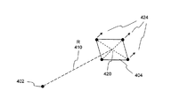
境界要素216は、爆発からの爆発圧を例えばフリートレンダー方程式を用いて実験的に決定することができるよう位置している。図4は、境界要素のセグメント404の中心420あるいは重心(図示せず)における爆発圧が演算されることを示す図である。爆発圧は、以下の時間および特有の距離「Z」の関数である:P=P(Z,t)、ここでZ=R/M1/3。「R」410は、爆発源402とセグメント404の中心420との間の距離である。「M」は爆発源402の質量である。また、「t」は時間進行FEAにおけるシミュレーション時間である。例示的な爆発圧対時間曲線を、次の図5に示す。爆発圧から、1セットのノードの速度424を、ランキン−ユゴニオの関係式および実験的動圧減衰則を用いて計算することができる。
The
FEAモデル200において、有限要素は、爆発源202と境界要素216の層と間に必要ではない。爆発の時間進行シミュレーションは、1セットの適切な境界条件を、そのような関数を与えるよう構成された境界要素216の層に関連づけられた境界に沿った有限要素に適用することによって、行なうことができる。その結果、爆発による流体−構造体相互作用のシミュレーションを行なう演算時間が低減される。したがって、従来技術のアプローチの問題および短所は、本発明によって克服される。
In the
FEAモデル200は、爆発源202の位置を指定することができるグローバル座標システム(図示せず)において定義される。さらに、爆発源202の特性は、質量および爆発時間を含んでいる。
The
図5は、本発明の一の実施形態にかかる、特定の位置における爆発による爆発圧500の圧力504対時間502の例示的な曲線を示すX−Yグラフである。爆発圧力500は、時間が0すなわちt0のとき、初期の周囲圧力P0 520(例えば開けた空間における大気圧力)と等しく、時間t1まで一定のままである。そして、爆発圧500は、爆発波がその特定の位置に達する瞬間に対応するピーク圧力P1 512へと跳ね上がる(ジャンプする)。ピーク圧力P1 512の大きさは、その特定の位置と爆発源との間の距離と、爆発源の質量と、の関数である。その後、爆発圧力500は減衰する。伝達媒体(例えば空気、水)のタイプおよび特定の位置によって、爆発圧500の後引き部分514が種々の形状に減衰することがある。図5に示す例示的な爆発圧500は、大気圧力P0 520より低い値に近づくが、他の値も可能である(例えば大気圧力より高い値や負圧(つまり時間軸より下の値)など)。フリートレンダーの方程式を、t1とt2との間の減衰を数学的に表わすよう用いることができる。一の態様において、フリートレンダーの方程式では、入射圧力Pincは以下の形を有する:
FIG. 5 is an XY graph showing an exemplary curve of pressure 504 of

ここで、時間t2は後引き部分514の圧力がP0 520に減衰する時間であり、αは波形減衰パラメータである。爆発圧500の負のフェーズ516(つまり、圧力が、環境圧力P0 520より低く低下している)は、約10倍の爆薬半径(チャージ半径(charge radius))より概ね大きな距離でのみ存在し、フリートレンダーの方程式によって考慮される。
Here, time t 2 is the time when the pressure of the trailing
境界要素のそれぞれのセグメントの爆発圧が演算されて、境界要素のそれぞれのノードに適用される1セットのノードの速度を決定するために用いられる。流体−構造体相互作用は、これらの適用されるノードの速度の境界条件と、それに加えて要素内部エネルギーおよび相対的な体積と、に基づいて、ALEベースの有限要素解析法を用いて、計算される。一の態様において、相対的な体積は、要素の当初と現在の密度との間の比として定義される。 The explosion pressure of each segment of the boundary element is computed and used to determine the velocity of a set of nodes applied to each node of the boundary element. Fluid-structure interactions are calculated using ALE-based finite element analysis based on these applied node velocity boundary conditions plus the element internal energy and relative volume. Is done. In one aspect, the relative volume is defined as the ratio between the original and current density of the element.
一の態様において、理想気体法則の状況内では、圧力と密度を、大気の熱力学の状態を記述するよう用いることができ、したがって、爆発波からの入射圧は、境界要素の直交点(quadrature point)において直接規定される。境界要素における大気の密度は、以下のように演算される。周囲の空気の密度ρoから衝撃を受けたとき、衝撃波面における大気の密度ρ1は次のランキン−ユゴニオのジャンプ不連続関係式から得られる。 In one aspect, within the ideal gas law context, pressure and density can be used to describe the thermodynamic state of the atmosphere, so the incident pressure from the explosion wave is the quadrature of the boundary element. point). The density of the atmosphere at the boundary element is calculated as follows. When an impact is received from the surrounding air density ρ o , the atmospheric density ρ 1 at the shock wave front is obtained from the following Rankine-Yugonio jump discontinuity relation.
理想気体として扱う場合、大気の密度ρは、衝撃波面の通過後に、次の等エントロピー関係に従う。 When treated as an ideal gas, the density ρ of the atmosphere follows the following isentropic relationship after passing through the shock wave front.
爆発波の流れ条件を完全に記述するのに決定すべき残っているものは、爆発風における空気粒子の速度である。再びランキン−ユゴニオの関係式を受けて、衝撃波面における粒子速度「up」は次の式を用いて見つけられる。 What remains to be determined to fully describe the flow conditions of the explosion wave is the velocity of the air particles in the blast. Rankin again - receiving Hugoniot relations the particle velocity at the shock front "u p" is found using the following equation.
ここで、Coは、衝撃の到達の前の空気における音速である。方程式3および5は、比熱比γ=cp/cv=1.4の理想気体に当てはまる。
[0035]
次に、衝撃波面の動圧は次のように演算される。
Here, Co is the speed of sound in the air before reaching the impact. Equations 3 and 5 apply to an ideal gas with a specific heat ratio γ = c p / c v = 1.4.
[0035]
Next, the dynamic pressure of the shock wave front is calculated as follows.
そして、動圧の減衰は、次の関数的な形式に従う。 And the attenuation of dynamic pressure follows the following functional form.
ζは粒子速度の正の継続時間(positive duration)によって規格化された時間であり、φは減衰パラメータである。
[0036]
最後に、方程式4、6および7を以下の式と組み合わせて、爆発風における粒子速度「u」の判定のための手段が得られる。
ζ is the time normalized by the positive duration of the particle velocity, and φ is the damping parameter.
[0036]
Finally, equations 4, 6 and 7 are combined with the following equation to provide a means for determining the particle velocity “u” in the blast:
この速度は、爆発に面する境界要素のセグメントの中心あるいは重心における粒子に対するものであり、また、続いて要素のノードに面積荷重法(area−weighted fashion)により分配される。 This velocity is for particles in the center or center of gravity of the segment of the boundary element facing the explosion and is subsequently distributed to the element nodes by an area-weighted fashion.
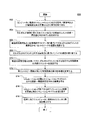
次に図6を参照して、フローチャートを、本発明の実施形態にかかる、任意ラグランジュ‐オイラー(ALE)法に基づく有限要素解析法を用いた、爆発による流体−構造体相互作用をシミュレートする例示的なプロセス600として示す。プロセス600は、好ましくは先の図面とともに理解され、ソフトウェアにおいて実行できる。
Referring now to FIG. 6, a flowchart simulates fluid-structure interaction due to an explosion using a finite element analysis method based on the arbitrary Lagrange-Euler (ALE) method according to an embodiment of the present invention. Shown as
プロセス600は、ステップ602において、コンピュータに、周囲流体を有する構造体と、爆発の爆発源に関係する1セットの特性と、の定義を受け取ることによってスタートする。ALEベースの有限要素アプリケーションモジュールは、コンピュータにインストールされている。構造体の定義は、物理的な寸法および特性を備える。また、流体の定義は、流体のタイプ(例えば空気、水あるいは他の流動性媒体)および物理的性質(例えば密度)を備える。爆発源の特性は、構造体に対するその源の位置や質量などを含む。そして、ステップ604において、有限要素解析法モデルが、受け取られた定義に基づいて生成される。有限要素モデルは、少なくとも2つのグループの有限要素を有している。1つのグループは流体を表わす。また、他のグループは構造体を表わしている。さらに、境界要素の層が、また、流体の境界に生成される。それぞれの境界要素は、爆発源に面するセグメントを含んでおり、流体を表わすグループにおける特定の有限要素に対応している。それぞれの境界要素は、爆発圧の初期/境界条件を、受け取られた定義、例えば、爆発の位置および質量と、セグメントの位置と、流体の特性と、爆発の爆発時間と、に応じて適用できるよう、構成される。
流体は、三次元の連続体の要素(例えばソリッド要素)のグループと概して表わされる。流体を通じた衝撃波および爆発風の挙動と、流体−構造体相互作用と、を把握するために、有限要素の適切なサイズが、明示的時間積分のアンダーライン理論(underline theory)における要求に応じて決定され生成される。例えば、サイズは、爆発波の伝播を把握することを保証することができるほど十分に比較的小さくなければならない。それぞれのセグメントは、爆発の爆発圧が、ステップ606において、爆発源とセグメントとの間の距離と、爆発時間と、伝達媒体(つまり流体)と、に基づいて、実験式(例えばフリートレンダー方程式)から決定することができるよう、配置されている。言いかえれば、爆発源と境界要素のそれぞれとの間には、爆発波を伝達する流体のみが存在する。本発明の目的のうちの一つは、爆発の時間進行シミュレーションが実質的により効率的に(つまりより速いシミュレーションで)実行することができるような位置に、境界要素を配置し、これにより、ユーザ(例えば科学者、技術者)の生産性を増加させることにある。一の態様において、それぞれの境界要素における爆発圧は、図4に示すセグメントの重心において演算される。
A fluid is generally represented as a group of three-dimensional continuum elements (eg, solid elements). In order to understand the behavior of shock waves and blasts through fluids and fluid-structure interactions, the appropriate size of the finite element depends on the requirements in the underline theory of explicit time integration. Determined and generated. For example, the size must be relatively small enough to ensure that the propagation of explosion waves can be ascertained. Each segment has an empirical formula (e.g. a free-tender equation) based on the explosion pressure of the explosion in
次に、ステップ607において、爆発風速が、実験的爆発方程式(例えば、方程式3〜8)に基づいて、それぞれのセグメントにおける爆発圧から演算される。そして、爆発風速が、ステップ608において、境界要素のそれぞれのノードに割り当てられる。割り当てを、多くの公知の手順(例えば単純平均、加重平均、あるいは他の同等な質量保存方式)において実行することができる。ノードの速度がそれぞれの境界要素に適用された後、通常の明示的時間積分を、爆発の時間進行シミュレーションの現在のソリューションサイクルにおいて実行することができる。ステップ610において、それぞれの境界要素の内部エネルギーが、特定の状態方程式(例えば理想気体に適用されるガンマ則)によって演算される。内部エネルギーは、概して、有限要素のそれぞれの統合点において評価され、あるいは演算される。下位の要素は、1つの統合点のみを備える。一方、高位の要素は1つ以上の統合点を含んでいる。ステップ612において、それぞれの有限要素の相対的な体積が、等エントロピー関係を用いて演算され、これにより、ステップ614において現在のソリューションサイクルの流体−構造体相互作用の結果が得られる。ALE手法によって、メッシュ平滑化および結果の再マッピングオペレーションが、それぞれのソリューションサイクルの後に、行なわれる。
Next, in step 607, the explosion wind speed is calculated from the explosion pressure in each segment based on an experimental explosion equation (eg, equations 3-8). The explosion wind speed is then assigned to each node of the boundary element in
結果がそれぞれのソリューションサイクルにおいて得られた後、ステップ616において、ソリューション時間がインクリメントされて、合計シミュレーション時間に達するまで、次のソリューションサイクルにおける他の時間積分ソリューションを行なう。最後に、ステップ618において、シミュレーションにおけるすべてのソリューションサイクルの流体−構造体相互作用の結果を、コンピュータに連結されたモニタに表示することができ、これにより、ユーザが構造体への爆発衝撃を調査し理解するのを支援することができる。その後、プロセス600が終了する。
After the results are obtained in each solution cycle, in
一の側面において、本発明は、ここで説明した機能性を実行可能な1つ以上のコンピュータシステムに対してなされたものである。コンピュータシステム700の一例を図7に示す。コンピュータシステム700は、プロセッサ704などの1つ以上のプロセッサを有する。プロセッサ704はコンピュータシステム内部通信バス702に接続されている。種々のソフトウェアの実施形態を、この例示的なコンピュータシステムで説明する。この説明を読むと、他のコンピュータシステムおよび/またはコンピューターアーキテクチャーを用いて、本発明を実行するかが、関連する技術分野に習熟しているものには明らかになるであろう。
In one aspect, the invention is directed to one or more computer systems capable of performing the functionality described herein. An example of a
コンピュータシステム700は、また、メインメモリ708好ましくはランダムアクセスメモリ(RAM)を有しており、また二次メモリ710を有していてもよい。二次メモリ710は、例えば、1つ以上のハードディスクドライブ712、および/またはフレキシブルディスクドライブ、磁気テープドライブ、光ディスクドライブ、フラッシュメモリカードリーダなどに代表される1つ以上のリムーバブルストレージドライブ714を有することができる。リムーバブルストレージドライブ714は、よく知られている方法でリムーバブルストレージユニット718から情報をを読み取り、および/またはリムーバブルストレージユニット718に情報を書き込む。リムーバブルストレージユニット718は、リムーバブルストレージドライブ714によって読み取り・書き込みされるフレキシブルディスク、磁気テープ、光ディスク、フラッシュメモリなどを表わす。以下にわかるように、リムーバブルストレージユニット718は、コンピューターソフトウェアおよび/またはデータを内部に記憶しているコンピュータ記録可能な記憶媒体を有している。
別の実施形態において、二次メモリ710は、コンピュータプログラムあるいは他の命令をコンピュータシステム700にロードすることを可能にする他の同様な手段を有することもできる。そのような手段は、例えば、リムーバブルストレージユニット722とインターフェース720を有することができる。そのようなものの例は、プログラムカートリッジおよびカートリッジインターフェース(ビデオゲーム機に見られるようなものなど)と、リムーバブルメモリチップ(消去可能プログラマブルROM(EPROM)、ユニバーサルシリアルバス(USB)フラッシュメモリ、あるいはPROMなど)およびそれらに対応するソケットと、ソフトウェアおよびデータをリムーバブルストレージユニット722からコンピュータシステム700に転送することを可能にする他のリムーバブルストレージユニット722およびインターフェース720と、が含まれうる。一般に、コンピュータシステム700は、プロセススケジューリング、メモリ管理、ネットワーク管理およびI/Oサービスなどのタスクを行なうオペレーティングシステム(OS)ソフトウェアによって、制御され連係される。
In another embodiment, the secondary memory 710 may have other similar means that allow a computer program or other instructions to be loaded into the
通信インターフェース724も、また、バス702に接続することができる。通信インターフェース724は、ソフトウェアおよびデータがコンピュータシステム700と外部装置との間で転送されることを可能にする。通信インターフェース724の例には、モデム、ネットワークインターフェース(イーサネット(登録商標)・カードなど)、コミュニケーションポート、PCMCIA(Personal Computer Memory card International Association)スロットおよびカードなどが含まれうる。
A communication interface 724 can also be connected to the bus 702. Communication interface 724 allows software and data to be transferred between
コンピュータ700は、特定の通信手続(つまりプロトコル)を実行してデータを送受信する。一般的なプロトコルの1つは、インターネットにおいて一般に用いられているTCP/IP(Transmission Control Protocol/Internet Protocol)である。一般に、通信インターフェース724は、データファイルをデータネットワーク上で伝達される小さいパケットへ分割し、あるいは受信したパケットを元のデータファイルへと組み立てる(再構築する)、いわゆるパケットのアセンブル・リアセンブル管理を行う。さらに、通信用インターフェース724は、正しい宛先へ届くようそれぞれのパケットのアドレス部分に対処し、あるいはコンピュータ700が宛先となっているパケットを他に向かわせることなく確実に受信する。
The
この書類において、「コンピュータプログラム媒体」および「コンピュータが記憶可能な媒体」という用語は、リムーバブルストレージドライブ714および/またはハードディスクドライブ712に組み込まれたハードディスクなどの媒体を通常意味して用いられる。これらのコンピュータプログラム製品は、ソフトウェアをコンピュータシステム700に提供する手段である。本発明は、このようなコンピュータプログラム製品に対してなされたものである。
In this document, the terms “computer program medium” and “computer-storable medium” are used to generally mean a medium such as a hard disk that is incorporated in removable storage drive 714 and / or hard disk drive 712. These computer program products are means for providing software to
コンピュータシステム700は、また、コンピュータシステム700にモニタ、キーボード、マウス、プリンタ、スキャナ、プロッターなどにアクセスさせる入出力(I/O)インターフェース730を有していてもよい。
The
コンピュータプログラム(コンピュータ制御ロジックともいう)は、メインメモリ708および/または二次メモリ710にアプリケーションモジュール706として記憶される。コンピュータプログラムを、また、通信インターフェース724を介して受信することもできる。このようなコンピュータプログラムが実行された時、コンピュータプログラムによって、コンピュータシステム700がここに説明した本発明の特徴を実現することが可能になる。詳細には、コンピュータプログラムはが実行された時、コンピュータプログラムによって、プロセッサ704が本発明の特徴を実現することが可能になる。したがって、このようなコンピュータプログラムは、コンピュータシステム700のコントローラを表わしている。
A computer program (also referred to as computer control logic) is stored as an
ソフトウェアを用いて発明が実行されるある実施形態において、当該ソフトウェアは、コンピュータプログラム製品に記憶され、あるいは、リムーバブルストレージドライブ714、ハードドライブ712あるいは通信インターフェース724を用いてコンピュータシステム700へとロードされる。アプリケーションモジュール706は、プロセッサ704によって実行された時、アプリケーションモジュール706によって、プロセッサ704がここに説明した本発明の機能を実現させる。
In certain embodiments in which the invention is implemented using software, the software is stored in a computer program product or loaded into the
所望のタスクを実現するために、I/Oインターフェース730を介したユーザ入力によって、あるいは、よることなしに、1つ以上のプロセッサ704によって実行することができる1つ以上のアプリケーションモジュール706(たとえば、ALE法に基づいた有限要素解析法アプリケーションモジュール)を、メインメモリ708に、ロードすることもできる。動作においては、少なくとも1つのプロセッサ704がアプリケーションモジュール706のうち1つが実行されると、結果が演算されて二次メモリ710(つまりハードディスクドライブ712)に記憶される。有限要素解析法の結果および/または状況(例えば流体−構造体相互作用の結果)は、テキストあるいはグラフィック表現で、I/Oインターフェース730を介して、コンピュータに接続されたモニタへと、ユーザに報告される。
One or more application modules 706 (eg, that may be executed by one or
本発明を具体的な実施形態を参照して説明したが、これらの実施形態は単に例示的なものであって、本発明を限定するものではない。具体的に開示した例示的な実施形態に対する種々の変形あるいは変更が当業者には思いつくであろう。例えば、有限要素を6面体のソリッド要素として示し、説明した。他のタイプの同等な連続体の三次元の有限要素を、例えば、四面体要素を用いることもできる。さらに、セグメントを、二次元の四角形として示した。他の同等な物形状を、例えば、三角形、多辺形などを用いることもできる。さらに、フリートレンダー方程式を、爆発圧力の演算のための実験式と説明した。他のタイプの実験式を、例えば物理的な実験すなわちテストの結果を代わりに用いることもできる。最後に、ガンマ則を理想気体に対して説明したが、他の規定式および関係を他のタイプの流体(例えば水)に用いることもできる。つまり、本発明の範囲は、ここに開示した具体的な例示的実施形態に限定されるのではなく、当業者が容易に思いつくあらゆる変形は、本願の精神および認識範囲内および添付の特許請求の範囲の範囲内に含まれる。 Although the invention has been described with reference to specific embodiments, these embodiments are illustrative only and are not intended to limit the invention. Various modifications or alterations to the specifically disclosed exemplary embodiments will occur to those skilled in the art. For example, the finite element is shown and described as a hexahedral solid element. Other types of equivalent continuum three-dimensional finite elements can be used, for example, tetrahedral elements. In addition, the segments are shown as two-dimensional squares. Other equivalent object shapes, such as triangles and polygons, can also be used. Furthermore, the free-trender equation was explained as an empirical formula for calculating explosion pressure. Other types of empirical formulas could be used instead, for example physical experiment or test results. Finally, although the gamma law has been described for an ideal gas, other formulas and relationships can be used for other types of fluids (eg, water). In other words, the scope of the present invention is not limited to the specific exemplary embodiments disclosed herein, and all modifications readily conceived by those skilled in the art are within the spirit and scope of the present application and the appended claims. Included within range.
100 FEAモデル
102 爆発源
104 爆発波
112 第1FEAメッシュ
114 第2FEAメッシュ
200 有限要素解析法モデル
202 爆発源
212 有限要素
214 有限要素
216 境界要素
304 セグメント
306 境界要素
308 ノード
402 爆発源
404 セグメント
420 中心
410 距離
424 速度
500 爆発圧
512 ピーク圧力P1
520 初期周囲圧力P0
514 後引き部分
516 負のフェーズ
700 コンピュータシステム
702 バス
704 プロセッサ
706 アプリケーションモジュール
708 メインメモリ
710 二次メモリ
712 ハードディスクドライブ
714 リムーバブルストレージドライブ
718 リムーバブルストレージユニット
720 インターフェース
722 リムーバブルストレージユニット
724 通信インターフェース
730 I/Oインターフェース
100
520 Initial ambient pressure P 0
514 Trailing
Claims (12)
有限要素解析法アプリケーションモジュールがインストールされたコンピュータシステムにおいて、周囲流体を有する少なくとも1つの構造体および爆発の爆発源の1セットの特性の定義を受け取るステップと、
前記少なくとも1つの構造体を表す第1グループの有限要素と、前記周囲流体を表わす第2グループの有限要素と、該第2グループの外側の境界としての複数の境界要素により構成された層と、を有するFEAモデルを生成するステップであって、前記境界要素のそれぞれは、前記爆発源に面するセグメントを含んでいるとともに前記第2グループにおけるそれぞれ隣接している有限要素と関連付けられているステップと、
前記それぞれの境界要素のセグメントにおける、爆発圧および対応する爆発風速を1セットの実験的爆発方程式に基づいて演算するステップと、
複数のソリューションサイクルを含んでいる時間進行シミュレーションにおいて、前記それぞれの境界要素の1セットのノードの速度として爆発風速を最初に割り当てるステップと、
FEAモデルのメッシュ平滑化オペレーションを行なうことと、平滑化されたFEAモデルに流体−構造体相互作用の結果をマッピングすることと、等エントロピー関係を用いて前記第2グループにおけるそれぞれの有限要素の相対的な体積を演算することと、により時間進行シミュレーションの現在のソリューションサイクルにおいて流体−構造体相互作用の結果を得るステップと、
時間進行シミュレーションが完了した後、コンピュータシステムに連結された出力装置に、所望に応じて爆発の時間進行シミュレーションのソリューションサイクルのいずれかあるいはすべての、流体−構造体相互作用の結果を表示するステップと、
を備える方法。
Finite element analysis and a method that will be executed on a computer system for simulating an explosion in time-marching simulation using the (FEA),
Receiving a definition of a set of properties of at least one structure having an ambient fluid and an explosion source in a computer system having a finite element analysis application module installed thereon;
A first group of finite elements representing the at least one structure, a second group of finite elements representing the surrounding fluid, and a layer composed of a plurality of boundary elements as outer boundaries of the second group; Generating an FEA model with each of the boundary elements including a segment facing the explosion source and associated with a respective adjacent finite element in the second group; ,
Computing an explosion pressure and a corresponding explosion wind speed in each of the boundary element segments based on a set of experimental explosion equations;
Initially assigning an explosion wind speed as the speed of a set of nodes of each of the boundary elements in a time progression simulation comprising a plurality of solution cycles;
Performing a mesh smoothing operation of the FEA model, mapping the fluid-structure interaction results to the smoothed FEA model, and using the isentropic relationship to relative each finite element in the second group Obtaining a result of fluid-structure interaction in the current solution cycle of time progression simulation;
After the time progression simulation is completed, displaying the results of the fluid-structure interaction in any or all of the explosion time progression simulation solution cycles, as desired, on an output device coupled to the computer system; ,
A method comprising:
その方法が、
有限要素解析法アプリケーションモジュールがインストールされたコンピュータシステムにおける、周囲流体を有する少なくとも1つの構造体および爆発の爆発源の1セットの特性の定義を受け取るステップと、
前記少なくとも1つの構造体を表す第1グループの有限要素と、前記周囲流体を表わす第2グループの有限要素と、該第2グループの外側の境界としての複数の境界要素により構成された層と、を有するFEAモデルを生成するステップであって、前記境界要素のそれぞれは、前記爆発源に面するセグメントを含んでいるとともに前記第2グループにおけるそれぞれ隣接している有限要素と関連付けられているステップと、
前記それぞれの境界要素のセグメントにおける、爆発圧および対応する爆風風速を1セットの実験的爆発方程式に基づいて演算するステップと、
複数のソリューションサイクルを含んでいる時間進行シミュレーションにおいて前記それぞれの境界要素の1セットのノードの速度として爆発風速を最初に割り当てるステップと、
FEAモデルのメッシュ平滑化オペレーションを行なうことと、平滑化されたFEAモデルに流体−構造体相互作用の結果をマッピングすることと、等エントロピー関係を用いて前記第2グループにおけるそれぞれの有限要素の相対的な体積を演算することと、により時間進行シミュレーションの現在のソリューションサイクルにおいて流体−構造体相互作用の結果を得るステップと、
時間進行シミュレーションが完了した後、コンピュータシステムに連結された出力装置に、所望に応じて爆発の時間進行シミュレーションのソリューションサイクルのいずれかあるいはすべての、流体−構造体相互作用の結果を表示するステップと、
を備えている非一時的コンピュータ記録可能な記憶媒体。 In a time-marching simulation using finite element analysis method (FEA), when executed by a computer, a non-transitory computer records computer to control the computer system to perform a method of simulating an explosion has executable instructions A possible storage medium,
That way
Receiving a definition of a set of characteristics of at least one structure having an ambient fluid and an explosion source in a computer system having a finite element analysis application module installed thereon;
A first group of finite elements representing the at least one structure, a second group of finite elements representing the surrounding fluid, and a layer composed of a plurality of boundary elements as outer boundaries of the second group; Generating an FEA model with each of the boundary elements including a segment facing the explosion source and associated with a respective adjacent finite element in the second group; ,
Calculating an explosion pressure and a corresponding blast wind speed in each of the boundary element segments based on a set of experimental explosion equations;
Initially assigning an explosion wind speed as the speed of a set of nodes of each of the boundary elements in a time-lapse simulation comprising a plurality of solution cycles;
Performing a mesh smoothing operation of the FEA model, mapping the fluid-structure interaction results to the smoothed FEA model, and using the isentropic relationship to relative each finite element in the second group Obtaining a result of fluid-structure interaction in the current solution cycle of time progression simulation ;
After the time progression simulation is completed, displaying the results of the fluid-structure interaction in any or all of the explosion time progression simulation solution cycles, as desired, on an output device coupled to the computer system; ,
A non-transitory computer recordable storage medium.
FEAアプリケーションモジュールに関するコンピュータ可読コードを記憶するメインメモリと、
メインメモリに連結される少なくとも1つのプロセッサと、
を備えており、
前記少なくとも1つのプロセッサがメインメモリにおけるコンピュータ可読コードを実行しFEAアプリケーションモジュールに、
周囲流体を有する少なくとも1つの構造体および爆発の爆発源の1セットの特性の定義を受け取るオペレーションと、
前記少なくとも1つの構造体を表す第1グループの有限要素と、前記周囲流体を表わす第2グループの有限要素と、該第2グループの外側の境界としての境界要素により構成された層と、を有するFEAモデルを生成するオペレーションであって、前記境界要素のそれぞれは、前記爆発源に面するセグメントを含んでいるとともに前記第2グループにおけるそれぞれ隣接している有限要素と関連付けられているオペレーションと、
前記それぞれの境界要素のセグメントにおける、爆発圧および対応する爆風風速を1セットの実験的爆発方程式に基づいて演算するオペレーションと、
複数のソリューションサイクルを含んでいる時間進行シミュレーションにおいて最初に前記それぞれの境界要素の1セットのノードの速度として爆発風速を最初に割り当てるオペレーションと、
FEAモデルのメッシュ平滑化オペレーションを行なうことと、平滑化されたFEAモデルに流体−構造体相互作用の結果をマッピングすることと、等エントロピー関係を用いて前記第2グループにおけるそれぞれの有限要素の相対的な体積を演算することと、により時間進行シミュレーションの現在のソリューションサイクルにおいて流体−構造体相互作用の結果を得るオペレーションと、
時間進行シミュレーションが完了した後、前記メインメモリに連結された出力装置に、所望に応じて爆発の時間進行シミュレーションのソリューションサイクルのいずれかあるいはすべての流体−構造体相互作用の結果を表示するオペレーションと、
を実行させるシステム。
A system for simulating an explosion in a time progression simulation using finite element analysis (FEA) ,
A main memory storing computer readable code for the FEA application module;
At least one processor coupled to main memory;
With
The at least one processor executes computer readable code in main memory to an FEA application module;
Receiving a definition of a set of properties of at least one structure having an ambient fluid and an explosion source of the explosion;
A first group of finite elements representing the at least one structure; a second group of finite elements representing the surrounding fluid; and a layer constituted by boundary elements as boundaries outside the second group. An operation for generating an FEA model, wherein each of the boundary elements includes a segment facing the explosion source and is associated with a respective adjacent finite element in the second group;
Calculating an explosion pressure and a corresponding blast wind speed in each segment of the boundary element based on a set of experimental explosion equations;
First assigning an explosion wind speed as the speed of a set of nodes in each of the boundary elements in a time progression simulation including multiple solution cycles;
Performing a mesh smoothing operation of the FEA model, mapping the fluid-structure interaction results to the smoothed FEA model, and using the isentropic relationship to relative each finite element in the second group An operation to obtain the result of fluid-structure interaction in the current solution cycle of time progression simulation ,
After completion of the time progression simulation, an output device coupled to the main memory displays, as desired, the results of any or all fluid-structure interactions of the explosion time progression simulation solution cycle; ,
System to run.
Applications Claiming Priority (2)
| Application Number | Priority Date | Filing Date | Title |
|---|---|---|---|
| US16551109P | 2009-04-01 | 2009-04-01 | |
| US61/165,511 | 2009-04-01 |
Publications (3)
| Publication Number | Publication Date |
|---|---|
| JP2010244531A JP2010244531A (en) | 2010-10-28 |
| JP2010244531A5 JP2010244531A5 (en) | 2013-03-07 |
| JP5330300B2 true JP5330300B2 (en) | 2013-10-30 |
Family
ID=42236989
Family Applications (1)
| Application Number | Title | Priority Date | Filing Date |
|---|---|---|---|
| JP2010069823A Active JP5330300B2 (en) | 2009-04-01 | 2010-03-25 | Explosion simulation in finite element analysis |
Country Status (4)
| Country | Link |
|---|---|
| US (1) | US8200464B2 (en) |
| EP (1) | EP2237175A1 (en) |
| JP (1) | JP5330300B2 (en) |
| CN (1) | CN101858713B (en) |
Families Citing this family (33)
| Publication number | Priority date | Publication date | Assignee | Title |
|---|---|---|---|---|
| CA2648441A1 (en) * | 2007-12-31 | 2009-06-30 | Exocortex Technologies, Inc. | Fast characterization of fluid dynamics |
| US20100185420A1 (en) * | 2009-01-18 | 2010-07-22 | Ejiang Ding | Computer system for computing the motion of solid particles in fluid |
| US8200464B2 (en) * | 2009-04-01 | 2012-06-12 | Livermore Software Technology Corporation | Explosion simulation in finite element analysis |
| US11610037B2 (en) | 2009-12-29 | 2023-03-21 | Comsol Ab | System and method for accessing settings in a multiphysics modeling system using a model tree |
| CN102063539B (en) * | 2010-12-30 | 2013-03-27 | 北京航空航天大学 | Inertial platform residual stress release simulating method based on finite element |
| CN102254075B (en) * | 2011-08-12 | 2013-02-13 | 中国人民解放军第三军医大学第二附属医院 | Method for simulating simulation splash in high speed impact |
| US9146652B1 (en) * | 2011-08-31 | 2015-09-29 | Comsol Ab | System and method for creating user interfaces in a multiphysics modeling system |
| US8834163B2 (en) * | 2011-11-29 | 2014-09-16 | L-3 Communications Corporation | Physics-based simulation of warhead and directed energy weapons |
| US8855976B2 (en) * | 2012-01-17 | 2014-10-07 | Livermore Software Technology Corp. | Numerically simulating structural behaviors of a product using explicit finite element analysis with a mass scaling enhanced subcycling technique |
| US8855977B2 (en) * | 2012-01-17 | 2014-10-07 | Livermore Software Technology Corp. | Numerically simulating structural behaviors of a product using explicit finite element analysis with a combined technique of mass scaling and subcycling |
| US9217698B2 (en) | 2012-01-24 | 2015-12-22 | The United States Of America, As Represented By The Secretary, Department Of Health And Human Services | Device for simulating explosive blast and imaging biological specimen |
| US8744825B2 (en) * | 2012-02-13 | 2014-06-03 | Livermore Software Technology Corp. | Element refinement methods and systems in arbitrary lagrangian-eulerian (ALE) based finite element analysis |
| US9972128B2 (en) | 2012-07-20 | 2018-05-15 | The University Of British Columbia | Methods and systems for generating polycubes and all-hexahedral meshes of an object |
| CN103093055A (en) * | 2013-01-29 | 2013-05-08 | 江苏大学 | Linkage type row pile vibration isolation structure |
| EP3066645A4 (en) | 2013-11-04 | 2017-08-30 | The University Of British Columbia | Methods and systems for generating polycube segmentations from input meshes of objects |
| CN104252566B (en) * | 2014-09-28 | 2017-12-19 | 北京理工大学 | A kind of simplification of body structure and clamping deformation simulating analysis |
| EP3020913B1 (en) | 2014-11-17 | 2017-06-14 | Repsol, S.A. | Method of managing petro-chemical reservoir production and program product therefor |
| KR101672000B1 (en) * | 2015-03-25 | 2016-11-02 | 삼성중공업 주식회사 | Methods for modelling explosion pressure time history model |
| CN104915483B (en) * | 2015-05-28 | 2018-11-16 | 中国核电工程有限公司 | Building stability of foundation Method for Checking under a kind of geological process |
| US10210657B2 (en) | 2015-07-24 | 2019-02-19 | The University Of British Columbia | Methods and systems for hex-mesh optimization via edge-cone rectification |
| US9798841B2 (en) * | 2015-09-15 | 2017-10-24 | Livermore Software Technology Corp. | Systems and methods of conducting numerical simulation of an underwater explosion |
| US20170116360A1 (en) * | 2015-10-27 | 2017-04-27 | Livermore Software Technology Corporation | Efficient explicit finite element analysis of a product with a time step size control scheme |
| CN105653772B (en) * | 2015-12-28 | 2019-03-08 | 重庆邮电大学 | A kind of PBX blasting explosive granules compression moulding numerical simulation automation modeling method and system |
| CN105760613A (en) * | 2016-03-01 | 2016-07-13 | 北京空间飞行器总体设计部 | Load prediction method for pyrotechnic impact source of spacecraft |
| FR3091279B1 (en) * | 2018-12-26 | 2021-01-15 | Arianegroup Sas | Method and device for simulating a response of a loading of solid energetic material |
| CN110427694A (en) * | 2019-07-30 | 2019-11-08 | 中国人民解放军海军工程大学 | Explosive falls Safety Analysis Method and device |
| CN110916641A (en) * | 2019-11-29 | 2020-03-27 | 中国人民解放军总医院第六医学中心 | Intracranial pressure estimation method and device |
| CN112464338B (en) * | 2020-11-20 | 2023-09-12 | 西安近代化学研究所 | Method for predicting bending response of simply supported reinforced concrete beam under near field explosion |
| CN113553739B (en) * | 2021-07-06 | 2023-05-12 | 西安近代化学研究所 | Mixed explosive explosion output characteristic calculation method |
| KR102685087B1 (en) * | 2021-11-02 | 2024-07-16 | 국방과학연구소 | Apparatus for modeling transmission of secondary blast wave after destruction of structural member |
| CN115204002A (en) * | 2022-06-10 | 2022-10-18 | 潍柴动力股份有限公司 | Engine explosion impact load calculation method and system |
| CN115510704A (en) * | 2022-09-27 | 2022-12-23 | 中广核研究院有限公司 | Cladding tube blasting simulation method, device, equipment, storage medium and product |
| CN117332639B (en) * | 2023-09-26 | 2024-06-18 | 西南交通大学 | Method and equipment for identifying full-section excavation parameters of large-section tunnel of broken surrounding rock |
Family Cites Families (11)
| Publication number | Priority date | Publication date | Assignee | Title |
|---|---|---|---|---|
| US6678642B1 (en) * | 1998-10-08 | 2004-01-13 | Sandia Corporation | Method of and apparatus for modeling interactions |
| US20040226231A1 (en) * | 2003-02-27 | 2004-11-18 | Dlubak Francis C. | Blast resistant assemblies |
| US7231076B2 (en) * | 2004-06-30 | 2007-06-12 | Accuray, Inc. | ROI selection in image registration |
| JP3686420B1 (en) * | 2005-01-27 | 2005-08-24 | 三井造船株式会社 | Hull strength evaluation method and hull strength evaluation system |
| US7610184B1 (en) * | 2006-01-23 | 2009-10-27 | Itt Manufacturing Enterprises, Inc. | Sector meshing and neighbor searching for object interaction simulation |
| US7660480B1 (en) * | 2006-02-10 | 2010-02-09 | Livermore Software Technology Corporation | Practical fast mesh-free analysis |
| JP2008110622A (en) * | 2006-10-27 | 2008-05-15 | Ihi Marine United Inc | Method and program for analyzing bubble behavior and ship hull whipping response by underwater explosion |
| US7930154B2 (en) * | 2007-02-01 | 2011-04-19 | Continental Automotive Systems Us, Inc. | Fluid solid interaction included in impact simulation of fuel delivery module |
| US7599805B2 (en) * | 2007-03-12 | 2009-10-06 | Lockheed-Martin Corporation | Systems and methods for predicting supersonic acoustic signatures |
| US8200464B2 (en) * | 2009-04-01 | 2012-06-12 | Livermore Software Technology Corporation | Explosion simulation in finite element analysis |
| US20120047634A1 (en) * | 2009-05-14 | 2012-03-01 | Uday Vaidya | Long fiber thermoplastic helmet inserts and helmets and methods of making each |
-
2009
- 2009-10-21 US US12/582,947 patent/US8200464B2/en active Active
-
2010
- 2010-01-28 EP EP10151946A patent/EP2237175A1/en not_active Withdrawn
- 2010-02-26 CN CN201010132510.6A patent/CN101858713B/en active Active
- 2010-03-25 JP JP2010069823A patent/JP5330300B2/en active Active
Also Published As
| Publication number | Publication date |
|---|---|
| US8200464B2 (en) | 2012-06-12 |
| JP2010244531A (en) | 2010-10-28 |
| US20100256957A1 (en) | 2010-10-07 |
| CN101858713A (en) | 2010-10-13 |
| EP2237175A1 (en) | 2010-10-06 |
| CN101858713B (en) | 2014-04-02 |
Similar Documents
| Publication | Publication Date | Title |
|---|---|---|
| JP5330300B2 (en) | Explosion simulation in finite element analysis | |
| Bull et al. | Simulation of the Taylor–Green vortex using high-order flux reconstruction schemes | |
| KR102544597B1 (en) | Methods and systems for simulating structural behaviors of reinforced concrete in finite element analysis | |
| US8306793B2 (en) | Systems and methods of performing vibro-acoustic analysis of a structure | |
| US8744825B2 (en) | Element refinement methods and systems in arbitrary lagrangian-eulerian (ALE) based finite element analysis | |
| US11281824B2 (en) | Authoring loading and boundary conditions for simulation scenarios | |
| US7702490B1 (en) | Method and system for adaptive mesh-free shell structures | |
| JP2014174990A (en) | Numerical simulation of fsi using space-time ce/se solver with moving mesh for fluid domain | |
| US20180239848A1 (en) | Numerical Blast Simulation Methods and Systems Thereof | |
| US20150112653A1 (en) | Smoothed Particle Galerkin Formulation for Simulating Physical Behaviors in Solids Mechanics | |
| JP2011248882A (en) | Hybrid element having solid/sph coupling effect | |
| US20110282637A1 (en) | Numerical simulation of airflow within porous materials | |
| CN106528903B (en) | System and method for performing digital simulation of underwater explosions | |
| JP2021002342A (en) | Fast method for computer-based simulation | |
| Stern et al. | Estimation of dynamic stability coefficients for aerodynamic decelerators using CFD | |
| US10452796B2 (en) | Dynamically-positioned search domain used in numerical simulation of an impact event between two objects | |
| US8855976B2 (en) | Numerically simulating structural behaviors of a product using explicit finite element analysis with a mass scaling enhanced subcycling technique | |
| US11188692B2 (en) | Turbulent boundary layer modeling via incorporation of pressure gradient directional effect | |
| US9020784B2 (en) | Methods for providing a bonded-particle model in computer aided engineering system | |
| Diehl et al. | Extraction of fragments and waves after impact damage in particle-based simulations | |
| CN113204911A (en) | Fluid-solid coupling simulation method and system for trailing edge deflection process of ram parafoil | |
| CN112682340A (en) | Automatic detection method for rotation direction of axial flow type cooling fan | |
| Hall et al. | Optimisation using smoothed particle hydrodynamics with volume-based geometry control | |
| US11893329B1 (en) | Fluid-structure interaction solver for transient dynamics of fracturing media | |
| JP7475103B1 (en) | Simulator development method, information processing system and program |
Legal Events
| Date | Code | Title | Description |
|---|---|---|---|
| A521 | Request for written amendment filed |
Free format text: JAPANESE INTERMEDIATE CODE: A523 Effective date: 20130121 |
|
| A621 | Written request for application examination |
Free format text: JAPANESE INTERMEDIATE CODE: A621 Effective date: 20130121 |
|
| A977 | Report on retrieval |
Free format text: JAPANESE INTERMEDIATE CODE: A971007 Effective date: 20130620 |
|
| A131 | Notification of reasons for refusal |
Free format text: JAPANESE INTERMEDIATE CODE: A131 Effective date: 20130625 |
|
| A521 | Request for written amendment filed |
Free format text: JAPANESE INTERMEDIATE CODE: A523 Effective date: 20130626 |
|
| TRDD | Decision of grant or rejection written | ||
| A01 | Written decision to grant a patent or to grant a registration (utility model) |
Free format text: JAPANESE INTERMEDIATE CODE: A01 Effective date: 20130723 |
|
| A61 | First payment of annual fees (during grant procedure) |
Free format text: JAPANESE INTERMEDIATE CODE: A61 Effective date: 20130725 |
|
| R150 | Certificate of patent or registration of utility model |
Ref document number: 5330300 Country of ref document: JP Free format text: JAPANESE INTERMEDIATE CODE: R150 Free format text: JAPANESE INTERMEDIATE CODE: R150 |
|
| R250 | Receipt of annual fees |
Free format text: JAPANESE INTERMEDIATE CODE: R250 |
|
| R250 | Receipt of annual fees |
Free format text: JAPANESE INTERMEDIATE CODE: R250 |
|
| R250 | Receipt of annual fees |
Free format text: JAPANESE INTERMEDIATE CODE: R250 |
|
| R250 | Receipt of annual fees |
Free format text: JAPANESE INTERMEDIATE CODE: R250 |
|
| R250 | Receipt of annual fees |
Free format text: JAPANESE INTERMEDIATE CODE: R250 |
|
| R250 | Receipt of annual fees |
Free format text: JAPANESE INTERMEDIATE CODE: R250 |
|
| R250 | Receipt of annual fees |
Free format text: JAPANESE INTERMEDIATE CODE: R250 |
|
| R250 | Receipt of annual fees |
Free format text: JAPANESE INTERMEDIATE CODE: R250 |
|
| R250 | Receipt of annual fees |
Free format text: JAPANESE INTERMEDIATE CODE: R250 |