JP5328293B2 - Thermistor for respiratory system protected from environment - Google Patents
Thermistor for respiratory system protected from environment Download PDFInfo
- Publication number
- JP5328293B2 JP5328293B2 JP2008277054A JP2008277054A JP5328293B2 JP 5328293 B2 JP5328293 B2 JP 5328293B2 JP 2008277054 A JP2008277054 A JP 2008277054A JP 2008277054 A JP2008277054 A JP 2008277054A JP 5328293 B2 JP5328293 B2 JP 5328293B2
- Authority
- JP
- Japan
- Prior art keywords
- thermistor
- temperature probe
- container
- epoxy
- temperature
- Prior art date
- Legal status (The legal status is an assumption and is not a legal conclusion. Google has not performed a legal analysis and makes no representation as to the accuracy of the status listed.)
- Expired - Fee Related
Links
Images


Classifications
-
- G—PHYSICS
- G01—MEASURING; TESTING
- G01K—MEASURING TEMPERATURE; MEASURING QUANTITY OF HEAT; THERMALLY-SENSITIVE ELEMENTS NOT OTHERWISE PROVIDED FOR
- G01K13/00—Thermometers specially adapted for specific purposes
- G01K13/20—Clinical contact thermometers for use with humans or animals
- G01K13/25—Protective devices therefor, e.g. sleeves preventing contamination
-
- A—HUMAN NECESSITIES
- A61—MEDICAL OR VETERINARY SCIENCE; HYGIENE
- A61M—DEVICES FOR INTRODUCING MEDIA INTO, OR ONTO, THE BODY; DEVICES FOR TRANSDUCING BODY MEDIA OR FOR TAKING MEDIA FROM THE BODY; DEVICES FOR PRODUCING OR ENDING SLEEP OR STUPOR
- A61M16/00—Devices for influencing the respiratory system of patients by gas treatment, e.g. mouth-to-mouth respiration; Tracheal tubes
- A61M16/10—Preparation of respiratory gases or vapours
- A61M16/14—Preparation of respiratory gases or vapours by mixing different fluids, one of them being in a liquid phase
- A61M16/16—Devices to humidify the respiration air
-
- A—HUMAN NECESSITIES
- A61—MEDICAL OR VETERINARY SCIENCE; HYGIENE
- A61M—DEVICES FOR INTRODUCING MEDIA INTO, OR ONTO, THE BODY; DEVICES FOR TRANSDUCING BODY MEDIA OR FOR TAKING MEDIA FROM THE BODY; DEVICES FOR PRODUCING OR ENDING SLEEP OR STUPOR
- A61M16/00—Devices for influencing the respiratory system of patients by gas treatment, e.g. mouth-to-mouth respiration; Tracheal tubes
- A61M16/021—Devices for influencing the respiratory system of patients by gas treatment, e.g. mouth-to-mouth respiration; Tracheal tubes operated by electrical means
- A61M16/022—Control means therefor
- A61M16/024—Control means therefor including calculation means, e.g. using a processor
- A61M16/026—Control means therefor including calculation means, e.g. using a processor specially adapted for predicting, e.g. for determining an information representative of a flow limitation during a ventilation cycle by using a root square technique or a regression analysis
-
- A—HUMAN NECESSITIES
- A61—MEDICAL OR VETERINARY SCIENCE; HYGIENE
- A61M—DEVICES FOR INTRODUCING MEDIA INTO, OR ONTO, THE BODY; DEVICES FOR TRANSDUCING BODY MEDIA OR FOR TAKING MEDIA FROM THE BODY; DEVICES FOR PRODUCING OR ENDING SLEEP OR STUPOR
- A61M16/00—Devices for influencing the respiratory system of patients by gas treatment, e.g. mouth-to-mouth respiration; Tracheal tubes
- A61M16/08—Bellows; Connecting tubes ; Water traps; Patient circuits
- A61M16/0816—Joints or connectors
- A61M16/0841—Joints or connectors for sampling
-
- A—HUMAN NECESSITIES
- A61—MEDICAL OR VETERINARY SCIENCE; HYGIENE
- A61M—DEVICES FOR INTRODUCING MEDIA INTO, OR ONTO, THE BODY; DEVICES FOR TRANSDUCING BODY MEDIA OR FOR TAKING MEDIA FROM THE BODY; DEVICES FOR PRODUCING OR ENDING SLEEP OR STUPOR
- A61M16/00—Devices for influencing the respiratory system of patients by gas treatment, e.g. mouth-to-mouth respiration; Tracheal tubes
- A61M16/10—Preparation of respiratory gases or vapours
- A61M16/1075—Preparation of respiratory gases or vapours by influencing the temperature
- A61M16/109—Preparation of respiratory gases or vapours by influencing the temperature the humidifying liquid or the beneficial agent
-
- A—HUMAN NECESSITIES
- A61—MEDICAL OR VETERINARY SCIENCE; HYGIENE
- A61M—DEVICES FOR INTRODUCING MEDIA INTO, OR ONTO, THE BODY; DEVICES FOR TRANSDUCING BODY MEDIA OR FOR TAKING MEDIA FROM THE BODY; DEVICES FOR PRODUCING OR ENDING SLEEP OR STUPOR
- A61M16/00—Devices for influencing the respiratory system of patients by gas treatment, e.g. mouth-to-mouth respiration; Tracheal tubes
- A61M16/10—Preparation of respiratory gases or vapours
- A61M16/1075—Preparation of respiratory gases or vapours by influencing the temperature
- A61M16/1095—Preparation of respiratory gases or vapours by influencing the temperature in the connecting tubes
-
- A—HUMAN NECESSITIES
- A61—MEDICAL OR VETERINARY SCIENCE; HYGIENE
- A61M—DEVICES FOR INTRODUCING MEDIA INTO, OR ONTO, THE BODY; DEVICES FOR TRANSDUCING BODY MEDIA OR FOR TAKING MEDIA FROM THE BODY; DEVICES FOR PRODUCING OR ENDING SLEEP OR STUPOR
- A61M16/00—Devices for influencing the respiratory system of patients by gas treatment, e.g. mouth-to-mouth respiration; Tracheal tubes
- A61M16/01—Devices for influencing the respiratory system of patients by gas treatment, e.g. mouth-to-mouth respiration; Tracheal tubes specially adapted for anaesthetising
-
- A—HUMAN NECESSITIES
- A61—MEDICAL OR VETERINARY SCIENCE; HYGIENE
- A61M—DEVICES FOR INTRODUCING MEDIA INTO, OR ONTO, THE BODY; DEVICES FOR TRANSDUCING BODY MEDIA OR FOR TAKING MEDIA FROM THE BODY; DEVICES FOR PRODUCING OR ENDING SLEEP OR STUPOR
- A61M16/00—Devices for influencing the respiratory system of patients by gas treatment, e.g. mouth-to-mouth respiration; Tracheal tubes
- A61M16/04—Tracheal tubes
-
- A—HUMAN NECESSITIES
- A61—MEDICAL OR VETERINARY SCIENCE; HYGIENE
- A61M—DEVICES FOR INTRODUCING MEDIA INTO, OR ONTO, THE BODY; DEVICES FOR TRANSDUCING BODY MEDIA OR FOR TAKING MEDIA FROM THE BODY; DEVICES FOR PRODUCING OR ENDING SLEEP OR STUPOR
- A61M16/00—Devices for influencing the respiratory system of patients by gas treatment, e.g. mouth-to-mouth respiration; Tracheal tubes
- A61M16/06—Respiratory or anaesthetic masks
-
- A—HUMAN NECESSITIES
- A61—MEDICAL OR VETERINARY SCIENCE; HYGIENE
- A61M—DEVICES FOR INTRODUCING MEDIA INTO, OR ONTO, THE BODY; DEVICES FOR TRANSDUCING BODY MEDIA OR FOR TAKING MEDIA FROM THE BODY; DEVICES FOR PRODUCING OR ENDING SLEEP OR STUPOR
- A61M16/00—Devices for influencing the respiratory system of patients by gas treatment, e.g. mouth-to-mouth respiration; Tracheal tubes
- A61M16/10—Preparation of respiratory gases or vapours
- A61M16/14—Preparation of respiratory gases or vapours by mixing different fluids, one of them being in a liquid phase
- A61M16/16—Devices to humidify the respiration air
- A61M16/162—Water-reservoir filling system, e.g. automatic
-
- A—HUMAN NECESSITIES
- A61—MEDICAL OR VETERINARY SCIENCE; HYGIENE
- A61M—DEVICES FOR INTRODUCING MEDIA INTO, OR ONTO, THE BODY; DEVICES FOR TRANSDUCING BODY MEDIA OR FOR TAKING MEDIA FROM THE BODY; DEVICES FOR PRODUCING OR ENDING SLEEP OR STUPOR
- A61M2202/00—Special media to be introduced, removed or treated
- A61M2202/02—Gases
- A61M2202/0208—Oxygen
-
- A—HUMAN NECESSITIES
- A61—MEDICAL OR VETERINARY SCIENCE; HYGIENE
- A61M—DEVICES FOR INTRODUCING MEDIA INTO, OR ONTO, THE BODY; DEVICES FOR TRANSDUCING BODY MEDIA OR FOR TAKING MEDIA FROM THE BODY; DEVICES FOR PRODUCING OR ENDING SLEEP OR STUPOR
- A61M2202/00—Special media to be introduced, removed or treated
- A61M2202/02—Gases
- A61M2202/0241—Anaesthetics; Analgesics
-
- A—HUMAN NECESSITIES
- A61—MEDICAL OR VETERINARY SCIENCE; HYGIENE
- A61M—DEVICES FOR INTRODUCING MEDIA INTO, OR ONTO, THE BODY; DEVICES FOR TRANSDUCING BODY MEDIA OR FOR TAKING MEDIA FROM THE BODY; DEVICES FOR PRODUCING OR ENDING SLEEP OR STUPOR
- A61M2205/00—General characteristics of the apparatus
- A61M2205/33—Controlling, regulating or measuring
- A61M2205/3368—Temperature
-
- A—HUMAN NECESSITIES
- A61—MEDICAL OR VETERINARY SCIENCE; HYGIENE
- A61M—DEVICES FOR INTRODUCING MEDIA INTO, OR ONTO, THE BODY; DEVICES FOR TRANSDUCING BODY MEDIA OR FOR TAKING MEDIA FROM THE BODY; DEVICES FOR PRODUCING OR ENDING SLEEP OR STUPOR
- A61M2205/00—General characteristics of the apparatus
- A61M2205/50—General characteristics of the apparatus with microprocessors or computers
-
- Y—GENERAL TAGGING OF NEW TECHNOLOGICAL DEVELOPMENTS; GENERAL TAGGING OF CROSS-SECTIONAL TECHNOLOGIES SPANNING OVER SEVERAL SECTIONS OF THE IPC; TECHNICAL SUBJECTS COVERED BY FORMER USPC CROSS-REFERENCE ART COLLECTIONS [XRACs] AND DIGESTS
- Y10—TECHNICAL SUBJECTS COVERED BY FORMER USPC
- Y10T—TECHNICAL SUBJECTS COVERED BY FORMER US CLASSIFICATION
- Y10T29/00—Metal working
- Y10T29/49—Method of mechanical manufacture
- Y10T29/49002—Electrical device making
- Y10T29/49082—Resistor making
- Y10T29/49085—Thermally variable
Description
本発明は、一般に、加湿システムを組み込んだ呼吸器システムに関し、より詳細には、こうした呼吸器システム内の所望の位置で呼吸可能なガスの温度を感知する温度プローブに関する。 The present invention relates generally to respiratory systems that incorporate humidification systems, and more particularly to temperature probes that sense the temperature of breathable gas at a desired location within such respiratory systems.
呼吸器システムは、酸素、麻酔ガス、および/または空気など呼吸可能なガスを患者の口、鼻、あるいは気道に直接供給して、患者の呼吸を助け、あるいは楽にするものである。呼吸器システムの一部として換気装置を使用して、呼吸可能なガスを患者に吸息肢ホースまたは導管を通して送ることができる。呼息肢ホースまたは導管を設けて、患者から空気を吐き出し可能にすることができる。 A respiratory system provides breathable gases, such as oxygen, anesthetic gas, and / or air, directly to the patient's mouth, nose, or airway to assist or ease the patient's breathing. A ventilator can be used as part of the respiratory system to deliver breathable gas to the patient through an inspiratory limb hose or conduit. An expiratory limb hose or conduit can be provided to allow the patient to exhale air.
通常、呼吸可能なガスを患者に供給する前に、ガスを暖めて加湿することが望ましい。そのため、多くの呼吸器システムは、水を保持するチャンバ、およびチャンバを温めるように適合された加熱器を含む、加熱ユニットを有する加湿システムを含む。チャンバは手動で再補充することができ、またはチャンバが空になったときに選択的にチャンバに充填する水源が存在する。呼吸可能なガスはチャンバを通過して加熱され加湿される。加熱ユニットおよびチャンバ構成の一例が特許文献1および特許文献2に示されている。吸息肢は加熱され加湿されたガスを患者に搬送し、呼息肢が存在する場合は、呼息肢は患者からの呼気および可能な他のガスを搬送する。吸息肢および/または呼息肢を、肢の内部など肢に沿って走る1つあるいは複数の細長いワイヤからなる加熱回路などによって加熱することもできる。加熱肢を有する呼吸回路の一例が、特許文献3に示されている。 Typically, it is desirable to warm and humidify the gas before supplying breathable gas to the patient. As such, many respiratory systems include a humidification system having a heating unit that includes a chamber that holds water and a heater that is adapted to warm the chamber. The chamber can be manually refilled, or there is a water source that selectively fills the chamber when the chamber is empty. The breathable gas passes through the chamber and is heated and humidified. An example of the heating unit and the chamber configuration is shown in Patent Document 1 and Patent Document 2. The inspiratory limb carries heated and humidified gas to the patient, and if the expiratory limb is present, the expiratory limb carries exhaled from the patient and other possible gases. The inspiratory limb and / or the expiratory limb may be heated, such as by a heating circuit consisting of one or more elongated wires running along the limb, such as inside the limb. An example of a breathing circuit having a heated limb is shown in Patent Document 3.
このタイプの呼吸器システムを通過する1つまたは複数のガスの所望の温度を維持するには、システムからの熱フィードバックに応答して、加熱ユニット内の加熱器および/または吸息肢と呼息肢内の加熱回路の温度を調整する必要がある。したがって、一部の呼吸器システムは、患者に供給される加熱され加湿されたガスの温度の感知などのために、1つまたは複数の位置に温度プローブを含む。温度プローブを加熱ユニットに操作可能に結合し、測定された温度に少なくとも部分的に基づいて、加熱器および/または1つあるいは複数の加熱回路への電力レベルを調整することができる。現在の呼吸器システム用の温度プローブは、通常、サーミスタを含んでおり、サーミスタはポリイミド管など円筒形容器内に包装され、その中にエポキシで固定され、埋込用樹脂によって温度プローブのプラスチックハウジングの内に全て保持される。導線がサーミスタに電気的に結合され、サーミスタから離れるように延び、ハウジングの反対側の端部で関連する温度ケーブルに電気的に結合されて、加熱ユニットと電気的に導通される。 In order to maintain a desired temperature of one or more gases passing through this type of respiratory system, in response to thermal feedback from the system, the heater and / or inspiratory limb and exhalation in the heating unit It is necessary to adjust the temperature of the heating circuit in the limb. Accordingly, some respiratory systems include temperature probes at one or more locations, such as for sensing the temperature of heated and humidified gas supplied to a patient. A temperature probe can be operably coupled to the heating unit to adjust the power level to the heater and / or one or more heating circuits based at least in part on the measured temperature. Current temperature probes for respiratory systems typically include a thermistor that is packaged in a cylindrical container, such as a polyimide tube, secured in epoxy therein, and a plastic housing for the temperature probe by an embedded resin. Are all stored in A conductor is electrically coupled to the thermistor, extends away from the thermistor, is electrically coupled to the associated temperature cable at the opposite end of the housing, and is in electrical communication with the heating unit.
呼吸器システムでは、加熱されたガスの湿度レベルは非常に高く、通常は100%もしくはそれに近い。加熱されたガスの温度に伴う高レベルの湿度により、プローブハウジング内に、かつサーミスタにかなりの水分の移動が生じると考えられる。したがって、水分が蓄積されて、サーミスタに電子ドリフトおよび/または機械的圧縮が生じて、サーミスタからの温度の読取りが不正確になり、信頼できないものになる。呼吸器システム用の以前のサーミスタベースのプローブでは、水分の蓄積が急激に生じて、デバイスが大抵わずか数日または数週間で使い物にならなくなる。より長期間の有用な寿命が必要である。水分のサーミスタ内への移動を低減する一配慮は、サーミスタの容器を(あるいは容器が使用されない場合はサーミスタを)ガラスまたはエポキシの大きいビーズ中に封じ込めることである。大きいビーズはサーミスタへの水分の問題を軽減して、プローブの寿命を延ばすことが予想されるが、こうした手法はサーミスタの温度応答を大幅に低減すると考えられる。したがって、温度の読取りが温度の実際の変化から過度に遅れをとり、加熱ユニットが加熱ユニット内の加熱器および/または1つあるいは複数の呼吸回路肢内の1つあるいは複数の加熱回路の十分な温度調整を行なうことができなくなる。
本発明は、サーミスタが環境から保護されて、サーミスタ内への水分の移動が低減され、サーミスタの温度応答に悪影響が与えられない、呼吸器システムで使用されるサーミスタベースの温度プローブを提供する。 The present invention provides a thermistor-based temperature probe for use in a respiratory system in which the thermistor is protected from the environment, moisture movement into the thermistor is reduced, and the temperature response of the thermistor is not adversely affected.
そのため、本発明の原理によれば、プローブハウジングの先端などにあるプローブハウジングの空洞は、サーミスタおよびサーミスタの関連する容器をぴったりと受容して、容器がプローブハウジングのプラスチックと緊密な伝熱関係になるように配置されるサイズであり、容器は水分に対する障壁を設けて、呼吸器システムの通常の動作で受ける高温および高湿度レベルに関わらず水分の移動が最低限に抑えられるように適合される。容器は有利には円筒形であり、両端が開放された管の形態をとることができ、または一端だけが開放された缶の形態をとることができる。サーミスタは管または缶内に配置され、エポキシが加えられて、サーミスタがその中に固定され、1つまたは複数のさもなければ開放された端部が、一端から1つまたは複数の導線が延びる状態で閉鎖される。 Therefore, according to the principles of the present invention, the probe housing cavity, such as at the tip of the probe housing, closely receives the thermistor and the associated container of the thermistor so that the container is in a close heat transfer relationship with the plastic of the probe housing. The container is adapted to provide a barrier to moisture and to minimize moisture transfer regardless of the high temperature and high humidity levels experienced during normal operation of the respiratory system. . The container is advantageously cylindrical and can take the form of a tube with open ends, or it can take the form of a can with only one end open. The thermistor is placed in a tube or can, epoxy is added, the thermistor is secured therein, and one or more otherwise open ends extend from one end to one or more leads Closed.
管の場合、サーミスタは軸方向に心合わせされ、すなわちサーミスタはさもなければ(エポキシがなければ)開放された端部から略等距離に配置されて、略軸方向の水分移動経路全てのバランスがとられる。缶の場合、サーミスタは閉鎖端付近に配置されて、最も可能性が高い水分移動経路を画定するさもなければ開放された端部から離れるように配置される。容器は金属またはプラスチックであり、プラスチックは有利にはポリイミドである。容器が金属の場合、サーミスタは有利には容器に接触して、金属と直接熱接触することによって、プローブハウジングに隣接する温度の変化に対するサーミスタの温度応答が向上される。容器がプラスチックの場合、本発明のさらなる態様によれば、サーミスタは容器から間隔をおいて配置され、容器と接触しないようになされる。そのため、サーミスタを容器内に設置する前に、サーミスタにエポキシを被覆して、サーミスタと容器の間に障壁を作成することができる。さらに有利には、サーミスタを半径方向にも心合わせして、容器の円筒形の側壁から略等距離に配置されるようにし、サーミスタへの略半径方向の水分移動経路全てのバランスがとられるようにする。エポキシ被覆が有利に塗布されて、サーミスタの周囲に略(半径方向に)均一の最大厚さを有して、サーミスタを半径方向に心合わせする助けをする。 In the case of a tube, the thermistor is centered in the axial direction, i.e., the thermistor is otherwise (if there is no epoxy) placed approximately equidistant from the open end to balance all of the substantially axial moisture transfer paths. Be taken. In the case of a can, the thermistor is positioned near the closed end and is positioned away from the otherwise open end that defines the most likely moisture transfer path. The container is metal or plastic, and the plastic is preferably polyimide. When the container is metal, the thermistor advantageously contacts the container and is in direct thermal contact with the metal, thereby improving the temperature response of the thermistor to changes in temperature adjacent to the probe housing. When the container is plastic, according to a further aspect of the invention, the thermistor is spaced from the container and is not in contact with the container. Therefore, before the thermistor is installed in the container, the thermistor can be coated with epoxy to create a barrier between the thermistor and the container. More advantageously, the thermistor is also centered in the radial direction so that it is positioned approximately equidistant from the cylindrical side wall of the container so that all of the substantially radial moisture transfer paths to the thermistor are balanced. To. An epoxy coating is advantageously applied to have a substantially (radially) uniform maximum thickness around the thermistor to help center the thermistor radially.
空洞は、サーミスタ容器の幅寸法に近似の幅寸法(直径など)を有する。そのため、本発明の他の態様によれば、空洞の直径は有利には約0.010から0.020インチだけサーミスタ容器の直径よりも大きく、容器が定位置にある状態で、約0.005から0.010インチ以下の環状の隙間が容器の周囲に生成されるようになされる。したがって、プローブハウジングとサーミスタ容器の間の隙間が十分に小さいため、サーミスタへの熱伝達に悪影響が与えられない。空洞のプローブ先端部の壁の厚さは非常に薄く、熱伝達の遅れが最低限に抑えられるようになされる。有利には、先端部の壁の厚さは約0.020インチ以下である。サーミスタ容器がプローブハウジングの空洞内に配置された状態で、プローブを通るサーミスタへの熱伝達経路は、特に呼吸器システムで使用される従来のサーミスタベースのプローブの伝熱経路と比較して非常に短く、サーミスタの応答時間は十分速く維持され、同時に水分移動に対する十分な障壁が設けられて、サーミスタが有用でなくなる前に少なくとも有益かつ有用な寿命が得られる。 The cavity has a width dimension (such as a diameter) that approximates the width dimension of the thermistor container. Thus, according to another aspect of the invention, the diameter of the cavity is advantageously greater than the diameter of the thermistor container by about 0.010 to 0.020 inches, and with the container in place, about 0.005. An annular gap of 0.010 inches or less is created around the container. Accordingly, since the gap between the probe housing and the thermistor container is sufficiently small, the heat transfer to the thermistor is not adversely affected. The wall thickness of the hollow probe tip is very thin so that heat transfer delay is minimized. Advantageously, the tip wall thickness is about 0.020 inches or less. With the thermistor container positioned within the probe housing cavity, the heat transfer path through the probe to the thermistor is very high, especially compared to the heat transfer path of conventional thermistor-based probes used in respiratory systems. Short, thermistor response time is maintained fast enough, while at the same time providing a sufficient barrier to moisture transfer, at least a useful and useful life is obtained before the thermistor becomes unusable.
上記により、サーミスタが環境から保護されて、サーミスタへの水分の移動が低減され、サーミスタの温度応答に悪影響が与えられない、呼吸器系で使用されるサーミスタベースの温度プローブが提供される。本発明の上記その他の目的、利点、および特徴は、添付の図面と併せて以下の詳細な説明を考慮すれば当業者にはより容易に明らかになるであろう。 The above provides a thermistor-based temperature probe for use in the respiratory system that protects the thermistor from the environment, reduces moisture movement to the thermistor, and does not adversely affect the temperature response of the thermistor. These and other objects, advantages and features of the present invention will become more readily apparent to those of ordinary skill in the art in view of the following detailed description in conjunction with the accompanying drawings.
本明細書に組み込まれ、本明細書の一部を構成する添付の図面は、上記の本発明の全般的な記載および以下の詳細な記載と併せて、本発明の実施形態を示し、本発明を説明する働きをするものである。 The accompanying drawings, which are incorporated in and constitute a part of this specification, illustrate embodiments of the present invention, together with the general description of the invention described above and the following detailed description. It works to explain.
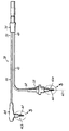
図1は呼吸可能なガスを患者12に供給するための例示の呼吸器システム10を示す図である。図で示した実施形態では、呼吸器システム10は、換気装置14、加熱ユニット18を有する加湿システム16、ディスポーザブルチャンバ20など水用の加熱可能な容器、並びに吸息肢22を画定する第1の細長いホースまたは導管22および呼息肢を画定する第2の細長いホースまたは導管24を有する呼吸回路21を含む。換気装置14は、酸素、麻酔ガス、および/または空気など呼吸可能なガスをガス導管25を通してチャンバ20の入口内に送る。水26は、袋またはびんなど給水部27から手動または自動的に注入することによってチャンバ20内に受容され、排出されうる。チャンバ20は加熱ユニット18の熱板および1つまたは複数の加熱素子(図示せず)など加熱器28によって加熱されて、チャンバ20内の水が加熱される。加熱された水蒸気29をチャンバ20内で水26の水面上に生成することもできる。導管25からのガスは加熱された水26および/または加熱された水蒸気29上またはその中を通過して加熱され加湿されてから、加熱され加湿されたガスとしてチャンバ20を出る。加湿システムの例が上記の特許文献1、特許文献2、同時係属中の2006年8月31日に出願された特許文献3、および2006年8月31に出願された特許文献4に示されている。4つの開示は全てその全体が参照により本明細書に組み込まれている。
FIG. 1 illustrates an exemplary
加熱され加湿されたガスは、チャンバ20から吸息肢22を通って患者12に流れる。そのため、吸息肢22の第1の端部は連結部材または接合部30によってチャンバ20に結合され、吸息肢22の第2の端部は呼吸用アッタチメント32に結合される。呼吸用アッタチメント32はガスを患者12に送出しやすくするものである。呼吸用アッタチメント32を気管内挿入管など観血的装置、またはガスの送出を促進するマスクなど非観血的装置に結合することができる。所望の場合は、吸息肢22に関連する加熱回路34を設けることによって、ガスが吸息肢22を通って呼吸用アッタチメント32に通過中に、ガスをさらに加熱することができる。他の加熱回路36を呼息肢24に関連付けることができる。呼息肢24は、患者12からの呼気および他の排出ガスが換気装置14、大気または他の場所に戻ることができるようにするものである。
Heated and humidified gas flows from the chamber 20 through the
呼吸器システム10は、加熱ユニット18に熱フィードバックを提供する1つまたは複数の温度プローブ42(本明細書で示した例示の実施形態で2つが使用される場合は別個に42aおよび42bと呼ばれる)を有する患者用温度ケーブル(PTC)38も含む。プローブから受信されたフィードバックにより、加熱ユニット18は、加熱器28および/または加熱回路34、36への電力レベルを変えて、患者12に供給されるガスの温度を適切な呼吸および肺の生存度をもたらす事前に選択した温度設定点に調整する。
The
図1および2で示したように、例示の一実施形態では、患者用温度ケーブル38は、第1の通信ケーブル43に結合された第1の温度プローブ42aを有する第1の通信ケーブル43、および第2の通信ケーブル44に結合された第2の温度プローブ42bを有する第2の通信ケーブル44を含む。第1の温度プローブ42aは連結部材30の開口部(図示せず)を通って部分的に挿入され、吸息肢22の流路内など、吸息肢22を通って流れる呼吸ガスと熱的に連通するように配置される。別法として、プローブ42aを吸息肢22の流路に隣接し、吸息肢22中を流れるガスと熱的に連通するように配置することができる。第1の温度プローブ42aはチャンバ20を出るガスの温度に応答し、加熱ユニット18に第1の通信ケーブル43によって電気的に結合される。第1の通信ケーブル43は加熱ユニット18に電気的に結合される端部48を有する。
As shown in FIGS. 1 and 2, in one exemplary embodiment, the
同様に、第2の温度プローブ42bを、呼吸用アッタチメント32を通して部分的に挿入し、呼吸用アッタチメント32を通って患者12の体内に流れる呼吸ガスと熱的に連通するように配置することができる。第2の温度プローブ42bを呼吸用アッタチメント32のガス流路内に直接、または流路に隣接するように、その中を流れるガスと熱的に連通するように配置することができる。第2の温度プローブ42bは第2の通信ケーブル44によって加熱ユニット18に電気的に結合され、第2の通信ケーブル44も加熱ユニット18に電気的に結合される端部50を有する。端部48および50をコネクタ52で共に有利に固定して、第1の通信ケーブル43および第2の通信ケーブル44を加熱ユニット18上の対合するソケット(図示せず)に結合しやすくすることができる。
Similarly, the
加熱ユニット18内の制御装置54は、56で加熱器28と(かつ57で加熱回路34、36と)操作可能に関連し、加熱器28(並びにそれぞれ吸息肢22および呼息肢24内の加熱回路34、36)の通電を制御して、水26を望む通りに加熱し、水蒸気29を生成し、それによってチャンバ20を通過する呼吸可能なガスを加熱し加湿する。制御装置54内のマイクロプロセッサまたは論理回路(図示せず)が1つまたは複数の温度プローブ42からの情報を処理して、加熱器28(または加熱回路34および36)に供給される電力の調整を行なう必要があるかどうかが判断される。加熱器28および/または加熱回路34、36に供給される電力を調整するための制御装置54および関連する制御論理の多様な詳細が、以下の現在出願されている米国特許出願である、特許文献6、特許文献7、特許文献8、特許文献9、特許文献10、および特許文献11に記載されている。上記の現在出願されている米国特許出願全てが参照によりそれぞれその全体が本明細書に組み込まれている。
A
図2は、患者用温度ケーブル38をさらに詳細に示す図である。第1の温度プローブ42aを第1の通信ケーブル43にオーバーモールド58によって結合することができる。より具体的には、通常は、第1の通信ケーブル43の端部部分60が第1の温度プローブ42a内に挿入され、ケーブルタイ(図示せず)など従来の締結具によって外側ハウジング62(図3)に固定される。連結部を強化するため、オーバーモールド58を端部部分60および外側ハウジング62の少なくとも近位部分上に成形することができる。端部部分60および第1の温度プローブ42aを実質的に軸63に沿って結合して、患者用温度ケーブル38が呼吸器システム10内に適切に位置付けられるようにすることができる。
FIG. 2 shows the
同様に、第2の温度プローブ42bをオーバーモールド64によって第2の通信ケーブル44に結合することができる。第2の温度プローブ42bは、以下にかなり詳細に記載するように、第1の温度プローブ42aと同様の全般的な設計を有する。しかし、第2の温度プローブ42bの呼吸器システム10内の特定の位置により、第2の温度プローブ42bを第2の通信ケーブル44に対して垂直に配置することができる。したがって、近位ハウジング62内に挿入され、直角の屈曲部およびオーバーモールド64を含み、またはそれに直接隣接する第2の通信ケーブル44の一部を、第2の温度プローブ42bの第2の通信ケーブル44に対する特定の方向付けに対応するように構成することができる。
Similarly, the
オーバーモールド58および64はひずみを軽減して、通信ケーブル43および44が屈曲され、または張力を受けるように配置された場合に、それぞれ温度プローブ42から分離しないようにする。一実施形態では、オーバーモールド58および64はSantoprene TPV 8281−90MEDなど熱可塑性樹脂から形成され、約デュロメーター90ショア(Shore)Aを有する。オーバーモールド58および64の形状および材料を人間工学的機能を果たすように選択して、患者用温度ケーブル38を把持しやすくし、温度プローブ42を扱いやすくすることもできる。さらに、オーバーモールド58および64が水分障壁として働き、温度プローブ42のワイヤおよび他の内部構成要素を損傷から保護するように設計することができる。
Overmolds 58 and 64 reduce strain so that they do not separate from
図3をさらに参照すると、温度プローブ42の1つの断面図が示されている。理解されるように、第1および第2の温度プローブ42aおよび42bは実質的に同一である。温度プローブ42は、その中に空洞66を画定する先端部65を有するプラスチックプローブハウジング62を含む。空洞66内には略円筒形の容器68が存在し、容器68内にサーミスタ70がエポキシ72によって固定される(図4Aおよび4Bを参照)。埋込用樹脂74をプローブハウジング62の内部75に充填することができる。プローブハウジング62は容器68の外側の空洞66の任意の態様を含む。サーミスタ70に電気的に結合された(1つだけ示してある)導線76は、容器68から外側に延び、埋込用樹脂74を通って適切な通信ケーブル43または44に電気的に結合される(導線76を空洞壁付近を通るように、または本明細書で示すように空洞壁の中央を通過するように配置することができる)。空洞66は、容器68をその中にぴったりと受容するサイズであり、容器68を先端部65でプラスチックハウジング62と緊密な伝熱関係になるように位置付ける。そのため、空洞66の幅寸法は、容器68の直径に非常に近似したものである。一実施形態では、空洞66の公称直径は約0.020インチ以下であり、より有利には約0.020インチ以下であり容器68の直径よりも大きい。容器68が先端部65の閉鎖底部78に隣接して先端部65内の半径方向に心合わせされた状態では、プローブハウジング62と容器68の間の公称半径方向距離は、有利には約0.010インチ以下、さらに有利には約0.005インチ以下であり、プローブハウジング62から容器68への熱伝達が悪影響を受けないようになされる。
With further reference to FIG. 3, a cross-sectional view of one of the temperature probes 42 is shown. As will be appreciated, the first and second temperature probes 42a and 42b are substantially identical. The
先端部65の領域内のプローブハウジング62もプローブハウジング62を通る空洞66内への伝熱経路を最小限に抑えるサイズになされる。そのため、一実施形態では、プローブハウジング62の壁の厚さは、少なくとも先端部65の領域では、約0.020インチ以下である。プローブハウジング62の壁の厚さが薄く、容器68が空洞66内に(空洞66内の埋込用樹脂74の有無に関係なく)ぴったりと嵌ることによって、プローブハウジング62を通るサーミスタ70への伝熱経路が十分に短くなり、プローブ42の外側の温度変化に対するサーミスタ70の温度応答を数秒間で測定することができると考えられる。これは呼吸器システムで使用される従来のサーミスタベースのプローブでは通常数分間かかると考えられているのと対照的である。
The
同時に、本発明の原理によれば、サーミスタ70は、容器68が、呼吸器システム10の通常の操作で受ける高い温度および湿度レベルに関わらず、サーミスタ70への水分の移動を最低限に抑えるように適合されることによって、環境から保護される。そのため、図4Aを参照すると、容器68は、開放端84と86の間に延びる略円筒形の側壁82を有し、その中に軸方向の細長い円筒形の空間88を画定する管80の形態でもよい。サーミスタ70は空間88内に配置され、エポキシ72によってその中に保持され、導線76が端部86を通って外に延びる状態で容器68内に固定される。有利には、サーミスタ70はサーミスタ70が端部84および86から略等距離になるように端部84と86の間で略軸方向に心合わせされ、それによって端部84、86などからの略軸方向の水分の移動経路全てのバランスがとられる。管80は、サーミスタ70を管80内に固定し、端部84および86を密封する助けにエポキシ72だけで十分であるように金属でもよい。また、サーミスタ70は有利には側壁82と接触することができる。管80がポリイミドなどプラスチックの場合、サーミスタ70はカプセルに封入され、管80内で略半径方向に心合わせされて、側壁82に接触せずに側壁82から略等距離に配置される。所望の場合は、図4で示したように、サーミスタ70を空間88内に配置する前に、サーミスタ70をエポキシの薄いカプセル化層90で被覆する。層90はエポキシ72と同じ材料でもよい。薄い層90は、サーミスタ70が側壁82と接触するのを阻止する助けをし、サーミスタ70を空間88内で半径方向に心合わせする助けをする。そのため、層90は有利には略均一の(半径方向の)最大厚さを有することができ、それによって、空間88内で半径方向にぴったりと嵌る層が提供される。層90を有するサーミスタが空間88内に挿入され、適切に(特に軸方向に)心合わせされた後、エポキシ72が加えられて、サーミスタ70が空間88内に固定される。
At the same time, according to the principles of the present invention, the
別法として、図4Bを参照すると、容器68は、下端など一端96が閉鎖され上端など他端98が開放された軸方向の細長い空間95を画定する略円筒形の側壁94を有する缶92の形態をとることができる。缶92は、管80を使用し、管80にふたを溶接し、または他の方法で閉鎖して、管80の端部84が閉鎖端96を画定することによって作成することができる。別法として、缶92が側壁94および閉鎖端96を有するように、引抜加工などによって形成することもできる。缶92が金属製の場合、サーミスタ70を閉鎖端96および/または側壁94と接触するように直接缶92内に配置し、次いでその中にエポキシ72で固定して端部98を閉鎖することができる。有利には、サーミスタ70が端部96の付近または端部96に配置されて、さもなければ(エポキシ72がなければ)開放された端部98からできるだけ離れるようにすることによって、開放端98であると考えられる最も可能性の高い水分移動源からの長い水分移動路が設けられる。缶92がポリイミドなどプラスチック製の場合、サーミスタ70を缶92内に挿入してエポキシ72で固定する前に、サーミスタ70を上記の層90で事前に被覆することができる。さらに、サーミスタ70を缶92内で有利に軸方向かつ/または半径方向に心合わせすることができる。
Alternatively, referring to FIG. 4B, the
エポキシ72が比較的高い熱伝導率かつ/または低デュロメーターを有して、サーミスタ70への良好な熱伝達をもたらし、サーミスタ70への強固な応力が回避されるように、エポキシ72を選択することができる。こうした特性を有するエポキシの一例は、Emerson & Cuming、National Starch & Chemical Companyから入手可能な低密度のシンタクチックフォームのエポキシ封入材、Stycast 1090である。逆に、埋込用樹脂74を比較的低い熱伝導率を有する材料から選択して、埋込用樹脂74を通る熱伝達を低減し、または最低限に抑えて、熱伝達をサーミスタ70に集中させることができる。埋込用樹脂74は、2つの部分からなる室温で硬化可能シリコーンでもよく、その一例はDow MDX4−4210であるが、プローブ42の所望の性能特性によって他の埋込用樹脂を使用することもできる。一部の埋込用樹脂74は容器68とプローブハウジング62の間の半径方向に薄い空間内に加えられることが予想されるが、低い熱伝導率の埋込用樹脂(図示せず)を最初に先端部65の領域に加えることによって、二重埋込温度プローブが提供される。この二重埋込温度プローブは、参照によりその全体が本明細書に組み込まれている、現在出願されている特許文献12に記載されている。
Selecting the epoxy 72 such that the epoxy 72 has a relatively high thermal conductivity and / or low durometer to provide good heat transfer to the
プローブハウジング62を、埋込用樹脂74よりも高い熱伝導率など、比較的高い熱伝導率を有する他に、比較的低い導電性、優れた耐薬品性、および製造の目的で高度な寸法精度を有するプラスチック材料から成形することができる。一実施形態では、外側ハウジング62をUdel(登録商標)GF−120などガラス繊維、またはSolvay Corporationから入手可能な同様のポリサルホン樹脂で強化した熱可塑性樹脂から成形することができる。
In addition to having a relatively high thermal conductivity, such as a higher thermal conductivity than the embedding
使用の際は、患者用温度ケーブル38の温度プローブ42が呼吸器システム10内に上記のように配置され、ケーブル38が加熱ユニット18に結合される。温度プローブ42は、吸息肢22を通って流れる加熱され加湿されたガスと熱的に連通し、ガスの温度情報を加熱ユニット18に通信する。温度プローブ42の特定の構造により、プローブはガスの熱変化に迅速に応答することができ、1つまたは複数のサーミスタ70への水分の透過に対する十分な障壁を提供して、1つまたは複数のサーミスタ70が有効でなくなるまでの少なくとも有益かつ有用な寿命が得られる。加熱ユニット18は、加熱器28および/または加熱回路34、36の温度を迅速に調整して、温度を設定点に維持することができる。温度プローブ42からの応答時間が速いため、加熱器28が同様の応答時間を有するように、すなわち加熱器28を迅速に加熱し、または冷却することができるように構成することができる。温度プローブ42の改善された応答時間を使用することができるこうした加熱器28の1つが、参照によりその全体が本明細書に組み込まれている、現在出願されている特許文献13に開示されている。温度プローブと加熱器の両方の応答時間が速いため、呼吸可能な1つまたは複数のガスの加熱および加湿の制御が向上されて、事前に選択した設定点に近似の公差が維持され、それによって従来の呼吸器システムで達成される設定点の公差の大幅な改善がなされる。
In use, the
上記により、サーミスタが環境から保護されて、サーミスタへの水分の移動が低減され、サーミスタの温度応答に悪影響が与えられない、呼吸器システムで使用されるサーミスタベースの温度プローブが提供される。 The above provides a thermistor-based temperature probe for use in a respiratory system that protects the thermistor from the environment, reduces moisture movement to the thermistor, and does not adversely affect the temperature response of the thermistor.
本発明を本発明の実施形態および特定の例の記載で示し、実施形態を幾分詳細に記載したが、添付の特許請求の範囲はこうした詳細に決して限定されないものとする。当業者は追加の利点および変更を容易に思いつくであろう。たとえば、ケーブル38はそれぞれ第1および第2のプローブ42aおよび42bに結合された2つのケーブル43および44を有するように図で示したが、理解されるように、ケーブル38はケーブル43または44の1つだけを有し、それがプローブ42と関連してもよい。また、理解されるように、温度プローブ42について、加湿システムを有する呼吸器システムとの関連で記載したが、本発明の温度プローブは、加熱された高湿度の環境での温度測定が望まれる広範な用途で使用可能である。したがって本発明は、本発明の広範な態様で、図で示し記載した特定の詳細、代表的な装置、および方法、並びに例示の例に限定されるものではない。したがって、全般的な発明の概念の範囲および精神から逸脱することなく、こうした詳細から離れることができる。
While the invention has been illustrated in the description of the embodiments and specific examples of the invention and the embodiments have been described in some detail, the appended claims are in no way intended to be limited to such details. Those skilled in the art will readily be able to conceive of additional advantages and modifications. For example, although
10 呼吸器システム
12 患者
14 換気装置
16 加湿システム
18 加熱ユニット
20 チャンバ
21 呼吸回路
22 吸息肢
24 呼息肢
25 ガス導管
26 水
27 給水部
28 加熱器
29 水蒸気
30 接合部
32 呼吸用アッタチメント
34、36 加熱回路
38 患者用温度ケーブル
42 温度プローブ
43 第1の通信ケーブル
44 第2の通信ケーブル
48、50 端部
52 コネクタ
54 制御装置
58、64 オーバーモールド
62 プローブハウジング
63 軸
65 先端部
66 空洞
68 容器
70 サーミスタ
72 エポキシ
74 埋込用樹脂
75 内部
76 導線
78 底部
80 管
82、94 側壁
84、86、98 開放端
88、95 空間
90 層
92 缶
96 閉鎖端
DESCRIPTION OF
Claims (20)
その中に軸方向の細長い空間(88、95)、及び、前記サーミスタ(70)を前記容器(68)の前記軸方向の細長い空間(88、95)内に固定するエポキシ(72)を中に有する略円筒形の容器(68)であって、前記サーミスタ(70)への水分の移動を最低限に抑える障壁が設けられるように適合された容器(68)と、
前記略円筒形の容器(68)の直径に近似のサイズの幅寸法を有する空洞(66)を画定するプラスチックハウジング(62)と、を備え、
前記容器(68)が前記空洞内にぴったりと受容されることを特徴とする温度プローブ。 The thermistor (70);
An axial elongate space (88, 95) therein and an epoxy (72) that secures the thermistor (70) within the axial elongate space (88, 95) of the container (68) therein. A generally cylindrical container (68) having a barrier (68) adapted to provide a barrier that minimizes moisture transfer to the thermistor (70);
A plastic housing (62) defining a cavity (66) having a width dimension approximate to the diameter of the generally cylindrical container (68);
A temperature probe characterized in that said container (68) is received snugly within said cavity.
前記封入したサーミスタを略円筒形の容器(68)の開放端(86、98)を通して前記略円筒形の容器(68)の軸方向の細長い空間(88、95)内に挿入する段階と、
前記封入したサーミスタ(70)を前記容器内にエポキシ(72)で固定し、前記エポキシ(72)が前記開放端(86、98)を密封する段階と、
前記容器(68)をその中にぴったりと受容するサイズのプラスチックハウジング(62)の空洞内に前記容器(68)を配置する段階と、
を含むことを特徴とする温度プローブの作成方法。 Encapsulating the thermistor (70) in a thin coating of epoxy (90);
Inserting the enclosed thermistor through the open ends (86, 98) of the generally cylindrical container (68) into the axially elongated space (88, 95) of the generally cylindrical container (68);
Fixing the enclosed thermistor (70) in the container with an epoxy (72), the epoxy (72) sealing the open ends (86, 98);
Placing the container (68) within a cavity of a plastic housing (62) sized to receive the container (68) snugly therein;
A method for producing a temperature probe , comprising:
Applications Claiming Priority (2)
| Application Number | Priority Date | Filing Date | Title |
|---|---|---|---|
| US11/927,077 | 2007-10-29 | ||
| US11/927,077 US8059947B2 (en) | 2007-10-29 | 2007-10-29 | Environmentally protected thermistor for respiratory system |
Publications (2)
| Publication Number | Publication Date |
|---|---|
| JP2009109496A JP2009109496A (en) | 2009-05-21 |
| JP5328293B2 true JP5328293B2 (en) | 2013-10-30 |
Family
ID=40307399
Family Applications (1)
| Application Number | Title | Priority Date | Filing Date |
|---|---|---|---|
| JP2008277054A Expired - Fee Related JP5328293B2 (en) | 2007-10-29 | 2008-10-28 | Thermistor for respiratory system protected from environment |
Country Status (4)
| Country | Link |
|---|---|
| US (1) | US8059947B2 (en) |
| EP (1) | EP2056082A3 (en) |
| JP (1) | JP5328293B2 (en) |
| AU (1) | AU2008237551B2 (en) |
Families Citing this family (25)
| Publication number | Priority date | Publication date | Assignee | Title |
|---|---|---|---|---|
| US8122882B2 (en) * | 2007-10-29 | 2012-02-28 | Smiths Medical Asd, Inc. | Rainout reduction in a breathing circuit |
| US8511305B2 (en) * | 2007-10-29 | 2013-08-20 | Smiths Medical Asd, Inc. | Redundant power control for respiratory system heaters |
| DE102008029192A1 (en) * | 2008-03-13 | 2009-09-24 | Epcos Ag | Sensor for detecting a physical quantity and method for manufacturing the sensor |
| WO2013092103A1 (en) * | 2011-12-22 | 2013-06-27 | Endress+Hauser Flowtec Ag | Method for recognising a droplet deposition on a heated temperature sensor |
| BR112014020972A2 (en) * | 2012-02-24 | 2017-07-04 | Koninklijke Philips Nv | system configured to provide respiratory therapy to an individual; and method for providing respiratory therapy to an individual |
| GB2539122B (en) * | 2012-03-15 | 2017-03-15 | Fisher & Paykel Healthcare Ltd | Respiratory gas humidification system |
| JP6388574B2 (en) * | 2012-04-27 | 2018-09-12 | フィッシャー アンド ペイケル ヘルスケア リミテッド | Usability characteristics of respiratory humidification system |
| KR101546836B1 (en) | 2013-05-14 | 2015-11-20 | 주식회사 멕 아이씨에스 | Dehumidifiction and humidification system |
| US10549060B2 (en) | 2013-06-25 | 2020-02-04 | ResMed Pty Ltd | Outlet connection assembly and method of making the same |
| CN108187208B (en) | 2013-06-25 | 2022-03-01 | 瑞思迈私人有限公司 | Air outlet connecting assembly and manufacturing method thereof |
| CA3176048A1 (en) | 2013-09-13 | 2015-03-19 | Fisher And Paykel Healthcare Limited | Humidification system |
| BR122017019835B1 (en) | 2013-09-13 | 2023-01-24 | Fisher & Paykel Healthcare Limited | HUMIDIFICATION SYSTEM AND ASSEMBLY METHOD OF A HUMIDIFICATION SYSTEM |
| JP2016540599A (en) | 2013-12-17 | 2016-12-28 | レスメド・リミテッドResMed Limited | Respiratory pressure treatment system |
| AU2014367362B2 (en) | 2013-12-20 | 2019-08-15 | Fisher & Paykel Healthcare Limited | Humidification system connections |
| WO2015119515A1 (en) | 2014-02-07 | 2015-08-13 | Fisher & Paykel Healthcare Limited | Respiratory humidification system |
| USD762843S1 (en) | 2014-03-18 | 2016-08-02 | Resmed Limited | Air delivery tube |
| US11173272B2 (en) | 2014-05-02 | 2021-11-16 | Fisher & Paykel Healthcare Limited | Gas humidification arrangement |
| AU2015259944B2 (en) | 2014-05-13 | 2020-07-02 | Fisher & Paykel Healthcare Limited | Usability features for respiratory humidification system |
| CN106535971B (en) | 2014-06-03 | 2020-12-04 | 费雪派克医疗保健有限公司 | Flow mixer for respiratory therapy system |
| US11278689B2 (en) | 2014-11-17 | 2022-03-22 | Fisher & Paykel Healthcare Limited | Humidification of respiratory gases |
| USD805630S1 (en) | 2016-02-02 | 2017-12-19 | Resmed Limited | Air delivery tube |
| AU2017371480B2 (en) | 2016-12-07 | 2022-11-03 | Fisher And Paykel Healthcare Limited | Sensing arrangements for medical devices |
| DE102018102600A1 (en) * | 2018-02-06 | 2019-08-08 | Tdk Electronics Ag | temperature sensor |
| DE102018102709A1 (en) * | 2018-02-07 | 2019-08-08 | Tdk Electronics Ag | Temperature sensor and a method of manufacturing the temperature sensor |
| US11682505B2 (en) | 2020-03-03 | 2023-06-20 | Deroyal Industries, Inc. | Radiation curable thermistor encapsulation |
Family Cites Families (47)
| Publication number | Priority date | Publication date | Assignee | Title |
|---|---|---|---|---|
| US2000400A (en) * | 1931-11-11 | 1935-05-07 | James G Maclaren | Pneumatic dispatch carrier |
| US3402378A (en) * | 1965-09-10 | 1968-09-17 | Aero Med Thermal Instr Company | Electronic clinical thermometer and probe therefor |
| US3593704A (en) * | 1967-12-11 | 1971-07-20 | Ardath M Schwab | Pulse sensor for body pulse rate measuring means |
| US3678751A (en) * | 1970-07-01 | 1972-07-25 | Carver A Mead | Thermometer probe |
| US3713899A (en) * | 1970-11-12 | 1973-01-30 | Ford Motor Co | Thermocouple probe |
| US3738173A (en) * | 1971-11-22 | 1973-06-12 | Ivac Corp | Temperature sensing probe and disposable probe cover |
| GB1545543A (en) * | 1975-07-23 | 1979-05-10 | Fisher & Paykel | Temperature sensors |
| US4098662A (en) * | 1975-12-24 | 1978-07-04 | Betz Laboratories, Inc. | Corrosion probe for use in measuring corrosion rate under specified heat transfer conditions |
| US4138878A (en) * | 1976-12-03 | 1979-02-13 | Rohrback Corporation | Method and apparatus for detecting and measuring scale |
| US4183248A (en) * | 1978-08-08 | 1980-01-15 | Rwb Labs | Fast response electronic thermometer probe |
| JPS5539006A (en) | 1978-09-13 | 1980-03-18 | Hitachi Ltd | Water-proof thermister |
| US4464981A (en) * | 1983-04-01 | 1984-08-14 | Bunn-O-Matic Corporation | Beverage making machine with hot water faucet |
| NZ206715A (en) * | 1983-12-22 | 1988-10-28 | Fisher & Paykel | Forming a thermistor temperature probe |
| JPS60219526A (en) | 1984-04-16 | 1985-11-02 | Terumo Corp | Electronic clinical thermometer and its preparation |
| JPS61111428A (en) * | 1984-11-06 | 1986-05-29 | Terumo Corp | Electronic clinical thermometer |
| JPS633101U (en) * | 1986-06-24 | 1988-01-11 | ||
| US5178468A (en) * | 1988-08-25 | 1993-01-12 | Terumo Kabushiki Kaisha | Temperature measuring probe and electronic clinical thermometer equipped with same |
| US4934831A (en) * | 1989-03-20 | 1990-06-19 | Claud S. Gordon Company | Temperature sensing device |
| JPH03118432A (en) | 1989-09-29 | 1991-05-21 | Terumo Corp | Electronic clinical thermometer and manufacture thereof |
| JP2527557Y2 (en) * | 1990-05-25 | 1997-03-05 | シチズン時計株式会社 | Structure of electronic thermometer |
| JP2566613Y2 (en) * | 1992-03-17 | 1998-03-30 | ティーディーケイ株式会社 | Temperature sensor |
| US5349946A (en) * | 1992-10-07 | 1994-09-27 | Mccomb R Carter | Microprocessor controlled flow regulated molecular humidifier |
| US5348397A (en) * | 1993-03-29 | 1994-09-20 | Ferrari R Keith | Medical temperature sensing probe |
| US5392770A (en) * | 1993-06-29 | 1995-02-28 | Clawson; Burrell E. | Tubing circuit systems for humidified respiratory gas |
| CA2148017A1 (en) * | 1995-04-27 | 1996-10-28 | Richard Montreuil | Device for digital reading of spa, pool and whirlpool water temperature |
| JP2000500359A (en) * | 1995-11-13 | 2000-01-18 | フィッシャー アンド ペイケル リミティド | Heated respiratory conduit |
| US5743646A (en) * | 1996-07-01 | 1998-04-28 | General Motors Corporation | Temperature sensor with improved thermal barrier and gas seal between the probe and housing |
| EP0818671A3 (en) * | 1996-07-12 | 1998-07-08 | Isuzu Ceramics Research Institute Co., Ltd. | A ceramic sheath type thermocouple |
| JPH10221176A (en) | 1997-02-04 | 1998-08-21 | Toshiba Glass Co Ltd | Electronic clinical thermometer |
| US5943473A (en) * | 1997-05-29 | 1999-08-24 | Levine; Walter | Heated cartridge humidifier |
| CA2617349C (en) * | 1997-06-17 | 2011-11-15 | Fisher & Paykel Healthcare Limited | Respiratory humidification system |
| JPH11132866A (en) * | 1997-10-24 | 1999-05-21 | Matsushita Electric Ind Co Ltd | Thermistor temperature sensor |
| US5943743A (en) | 1998-08-11 | 1999-08-31 | Builder's Best, Inc. | Hose clamp |
| JP2001242016A (en) | 2000-02-29 | 2001-09-07 | Citizen Electronics Co Ltd | Electronic clinical thermometer |
| US6918389B2 (en) * | 2000-03-21 | 2005-07-19 | Fisher & Paykel Healthcare Limited | Breathing assistance apparatus |
| JP2002022555A (en) * | 2000-07-05 | 2002-01-23 | Matsushita Electric Ind Co Ltd | Temperature sensor |
| US7043979B2 (en) * | 2001-01-31 | 2006-05-16 | Fisher & Paykel Healthcare Limited | Respiratory humidification system |
| AU2003281774B2 (en) * | 2002-07-31 | 2007-02-15 | Fisher & Paykel Healthcare Limited | Isolated temperature sensor for humidification system |
| US6988497B2 (en) * | 2002-09-18 | 2006-01-24 | Medex Cardio-Pulmonary, Inc. | Apparatus for equalizing air pressure in air respiratory system |
| US6676290B1 (en) * | 2002-11-15 | 2004-01-13 | Hsueh-Yu Lu | Electronic clinical thermometer |
| US6918696B2 (en) * | 2003-01-15 | 2005-07-19 | Denso Corporation | Temperature sensor and method for manufacturing the same |
| JP4620400B2 (en) * | 2004-07-16 | 2011-01-26 | 日本特殊陶業株式会社 | Temperature sensor and method of manufacturing temperature sensor |
| US7316507B2 (en) * | 2005-11-03 | 2008-01-08 | Covidien Ag | Electronic thermometer with flex circuit location |
| US7458718B2 (en) * | 2006-02-22 | 2008-12-02 | Honeywell International Inc. | Temperature sensor that achieves a fast response in an exhaust gas environment |
| US7665890B2 (en) * | 2006-06-22 | 2010-02-23 | Watlow Electric Manufacturing Company | Temperature sensor assembly and method of manufacturing thereof |
| US7722016B2 (en) * | 2006-08-31 | 2010-05-25 | Medex Cardio-Pulmonary, Inc. | Float for humidification chamber |
| US20080054497A1 (en) * | 2006-08-31 | 2008-03-06 | Medex Cardio-Pulmonary, Inc.. | Vented cap humidification system |
-
2007
- 2007-10-29 US US11/927,077 patent/US8059947B2/en not_active Expired - Fee Related
-
2008
- 2008-10-22 EP EP08167316.2A patent/EP2056082A3/en not_active Withdrawn
- 2008-10-28 AU AU2008237551A patent/AU2008237551B2/en not_active Ceased
- 2008-10-28 JP JP2008277054A patent/JP5328293B2/en not_active Expired - Fee Related
Also Published As
| Publication number | Publication date |
|---|---|
| AU2008237551A1 (en) | 2009-05-14 |
| JP2009109496A (en) | 2009-05-21 |
| EP2056082A2 (en) | 2009-05-06 |
| EP2056082A3 (en) | 2014-03-05 |
| US20090110378A1 (en) | 2009-04-30 |
| US8059947B2 (en) | 2011-11-15 |
| AU2008237551B2 (en) | 2014-05-29 |
Similar Documents
| Publication | Publication Date | Title |
|---|---|---|
| JP5328293B2 (en) | Thermistor for respiratory system protected from environment | |
| US8303173B2 (en) | Dual potting temperature probe | |
| AU2021250960B2 (en) | Medical tubes for respiratory systems | |
| EP2195061B1 (en) | A respiratory system | |
| US9717873B2 (en) | Rotating electrical connector ADN respiratory gas delivery system employing same | |
| JP6005631B2 (en) | Improved respiratory tract | |
| JP2021098029A (en) | Apparatus for supplying gases to patient | |
| US7396995B2 (en) | Connector | |
| AU2003281774B2 (en) | Isolated temperature sensor for humidification system | |
| CN103933651B (en) | The conduit used in breathing equipment | |
| US20110108031A1 (en) | Heated conduit for respiratory humidification | |
| CN110141752A (en) | The conduit used in breathing equipment | |
| TW201737958A (en) | Component for medical circuit | |
| KR102573287B1 (en) | filter assembly | |
| WO2012077052A1 (en) | Proximal humidifier comprising hydrophobic membrane | |
| WO2004108218A1 (en) | A probe and breathing circuit | |
| US20240024609A1 (en) | Concentric breathing circuit with boost zone | |
| CN214762714U (en) | Ventilation connector and ventilation treatment equipment |
Legal Events
| Date | Code | Title | Description |
|---|---|---|---|
| A521 | Request for written amendment filed |
Free format text: JAPANESE INTERMEDIATE CODE: A523 Effective date: 20090311 |
|
| A621 | Written request for application examination |
Free format text: JAPANESE INTERMEDIATE CODE: A621 Effective date: 20110905 |
|
| A977 | Report on retrieval |
Free format text: JAPANESE INTERMEDIATE CODE: A971007 Effective date: 20121114 |
|
| A131 | Notification of reasons for refusal |
Free format text: JAPANESE INTERMEDIATE CODE: A131 Effective date: 20121204 |
|
| A521 | Request for written amendment filed |
Free format text: JAPANESE INTERMEDIATE CODE: A523 Effective date: 20130304 |
|
| TRDD | Decision of grant or rejection written | ||
| A01 | Written decision to grant a patent or to grant a registration (utility model) |
Free format text: JAPANESE INTERMEDIATE CODE: A01 Effective date: 20130702 |
|
| A61 | First payment of annual fees (during grant procedure) |
Free format text: JAPANESE INTERMEDIATE CODE: A61 Effective date: 20130723 |
|
| R150 | Certificate of patent or registration of utility model |
Free format text: JAPANESE INTERMEDIATE CODE: R150 |
|
| LAPS | Cancellation because of no payment of annual fees |