JP5324775B2 - Carrier ring for carrier head - Google Patents
Carrier ring for carrier head Download PDFInfo
- Publication number
- JP5324775B2 JP5324775B2 JP2007298304A JP2007298304A JP5324775B2 JP 5324775 B2 JP5324775 B2 JP 5324775B2 JP 2007298304 A JP2007298304 A JP 2007298304A JP 2007298304 A JP2007298304 A JP 2007298304A JP 5324775 B2 JP5324775 B2 JP 5324775B2
- Authority
- JP
- Japan
- Prior art keywords
- annular
- carrier
- carrier ring
- ring
- retaining ring
- Prior art date
- Legal status (The legal status is an assumption and is not a legal conclusion. Google has not performed a legal analysis and makes no representation as to the accuracy of the status listed.)
- Active
Links
Images


Classifications
-
- B—PERFORMING OPERATIONS; TRANSPORTING
- B24—GRINDING; POLISHING
- B24B—MACHINES, DEVICES, OR PROCESSES FOR GRINDING OR POLISHING; DRESSING OR CONDITIONING OF ABRADING SURFACES; FEEDING OF GRINDING, POLISHING, OR LAPPING AGENTS
- B24B37/00—Lapping machines or devices; Accessories
- B24B37/27—Work carriers
- B24B37/30—Work carriers for single side lapping of plane surfaces
- B24B37/32—Retaining rings
-
- B—PERFORMING OPERATIONS; TRANSPORTING
- B24—GRINDING; POLISHING
- B24B—MACHINES, DEVICES, OR PROCESSES FOR GRINDING OR POLISHING; DRESSING OR CONDITIONING OF ABRADING SURFACES; FEEDING OF GRINDING, POLISHING, OR LAPPING AGENTS
- B24B37/00—Lapping machines or devices; Accessories
- B24B37/04—Lapping machines or devices; Accessories designed for working plane surfaces
-
- H—ELECTRICITY
- H01—ELECTRIC ELEMENTS
- H01L—SEMICONDUCTOR DEVICES NOT COVERED BY CLASS H10
- H01L21/00—Processes or apparatus adapted for the manufacture or treatment of semiconductor or solid state devices or of parts thereof
- H01L21/02—Manufacture or treatment of semiconductor devices or of parts thereof
- H01L21/04—Manufacture or treatment of semiconductor devices or of parts thereof the devices having at least one potential-jump barrier or surface barrier, e.g. PN junction, depletion layer or carrier concentration layer
- H01L21/18—Manufacture or treatment of semiconductor devices or of parts thereof the devices having at least one potential-jump barrier or surface barrier, e.g. PN junction, depletion layer or carrier concentration layer the devices having semiconductor bodies comprising elements of Group IV of the Periodic System or AIIIBV compounds with or without impurities, e.g. doping materials
- H01L21/30—Treatment of semiconductor bodies using processes or apparatus not provided for in groups H01L21/20 - H01L21/26
- H01L21/302—Treatment of semiconductor bodies using processes or apparatus not provided for in groups H01L21/20 - H01L21/26 to change their surface-physical characteristics or shape, e.g. etching, polishing, cutting
- H01L21/304—Mechanical treatment, e.g. grinding, polishing, cutting
Abstract
Description
[0001]本発明は、一般的に、基板の化学的機械的研磨に関し、より具体的には、化学的機械的研磨に用いるキャリアヘッドに関する。 [0001] The present invention relates generally to chemical mechanical polishing of substrates, and more specifically to a carrier head for use in chemical mechanical polishing.
[0002]集積回路は、典型的には、導電層、半導電層又は絶縁層のシリコン基板上への逐次的堆積によって、基板上に形成される。1つの製造ステップは、非平坦面を覆って充填層を堆積させることと、非平坦面が露出するまで、充填層を平坦化することとを伴う。例えば、導電性充填層を、パターン化された絶縁層上に堆積して、絶縁層中のトレンチ又はホールを充填することができる。次いで、充填層は、絶縁層の隆起したパターンが露出するまで研磨される。平坦化の後、絶縁層の隆起したパターンの間に残る導電層の部分は、基板上の薄膜回路間に導電路を提供するビア、プラグ及びラインを形成する。加えて、平坦化は、フォトリソグラフィのために基板表面を平坦化するのに必要である。 [0002] Integrated circuits are typically formed on a substrate by sequential deposition of a conductive layer, semiconductive layer, or insulating layer on a silicon substrate. One manufacturing step involves depositing a fill layer over the non-planar surface and planarizing the fill layer until the non-flat surface is exposed. For example, a conductive fill layer can be deposited on the patterned insulating layer to fill trenches or holes in the insulating layer. The fill layer is then polished until the raised pattern of the insulating layer is exposed. After planarization, the portions of the conductive layer that remain between the raised patterns of the insulating layer form vias, plugs and lines that provide conductive paths between the thin film circuits on the substrate. In addition, planarization is necessary to planarize the substrate surface for photolithography.
[0003]化学的機械的研磨(CMP)は、平坦化の1つの一般に認められた方法である。この平坦化方法は、典型的には、基板を、CMP装置のキャリアヘッド又はポリシングヘッドに取り付けることを要する。基板の露出した面は、回転ポリシングディスクパッド又はベルトパッドと対向して置かれる。ポリシングパッドは、標準的なパッド又は固定された研磨パッドのいずれかとすることができる。標準的なパッドは、耐久性のある粗面を有するのに対して、固定研磨パッドは、閉じ込め媒体内に封じ込められた研磨粒子を有する。キャリアヘッドは、制御可能な負荷を基板に提供し、基板を研磨パッドに押し付ける。キャリアヘッドは、ポリシング中に所定の位置に基板を支える保持リングを有する。少なくとも1つの化学反応性薬剤及び研磨粒子を含むスラリー等の研磨液が、研磨パッドの表面に供給される。 [0003] Chemical mechanical polishing (CMP) is one accepted method of planarization. This planarization method typically requires that the substrate be attached to a carrier head or polishing head of a CMP apparatus. The exposed surface of the substrate is placed opposite the rotating polishing disc pad or belt pad. The polishing pad can be either a standard pad or a fixed polishing pad. Standard pads have a durable rough surface, whereas fixed abrasive pads have abrasive particles encapsulated within a containment medium. The carrier head provides a controllable load on the substrate and presses the substrate against the polishing pad. The carrier head has a retaining ring that supports the substrate in place during polishing. A polishing liquid, such as a slurry containing at least one chemically reactive agent and abrasive particles, is supplied to the surface of the polishing pad.
[0004]一態様では、保持リングアセンブリについて説明する。保持リングアセンブリは、環状チャンバを提供するように形作られたフレキシブル膜と、フレキシブル膜の下に配置された環状保持リングとを有する。フレキシブル膜は、同心の内側及び外側側壁と、内側及び外側側壁の上部エッジから水平方向に延びる環状同心リム部と、環状下面と、環状下面から下へ延びる2つの環状同心突出部とを有する。環状保持リングは、基板のエッジを取り囲んで基板を保持するように構成された内面と、研磨パッドに接触するように構成された下面と、環状上面と、環状上面内の2つの環状同心凹部とを有する。フレキシブル膜の環状同心突出部は、環状保持リングの環状同心凹部に嵌合するように寸法付けられている。 [0004] In one aspect, a retaining ring assembly is described. The retaining ring assembly has a flexible membrane shaped to provide an annular chamber and an annular retaining ring disposed under the flexible membrane. The flexible membrane has concentric inner and outer sidewalls, an annular concentric rim extending horizontally from the upper edges of the inner and outer sidewalls, an annular lower surface, and two annular concentric protrusions extending downward from the annular lower surface. The annular retaining ring includes an inner surface configured to hold the substrate surrounding the edge of the substrate, a lower surface configured to contact the polishing pad, an annular upper surface, and two annular concentric recesses in the annular upper surface. Have The annular concentric protrusions of the flexible membrane are dimensioned to fit into the annular concentric recesses of the annular retaining ring.
[0005]本発明の実施は、以下の特徴のうちの1つ以上を含むことができる。フレキシブル膜の同心内側及び外側側壁は、保持リングの上環状面の下に延びる湾曲部を有してもよい。フレキシブル膜の環状同心リム部及び環状同心突出部は、内側及び外側側壁よりも厚くてもよい。フレキシブル膜の環状下面は、各々が、環状下面から下に延びる2つの環状同心突出部の間に配置された複数の円形ホールを有することができる。保持リングの環状上面は、各々が、2つの環状同心凹部の間に配置されて、フレキシブル膜が、保持リングを締結部材で保持リングに固着できるようにする複数の円形凹部を有することができる。フレキシブル膜は、キャリアヘッドにクランプすることができる。フレキシブル膜は、シリコン等の弾性材料で形成することができる。環状保持リングは、環状下面と、環状上面と、上部と下部との間の接合層とを有することができる。保持リングの環状下部は、複数の溝を有することができる。保持リングの環状上部は、その外面に沿って環状リップ部を有することができ、環状リップ部は、水平下面と、垂直外面と、非水平方向上面とを有する。保持リングの環状上面は、下環状面と上環状面とを有することができ、下環状面は、上環状面よりも幅が広い。 [0005] Implementations of the invention may include one or more of the following features. The concentric inner and outer sidewalls of the flexible membrane may have curved portions that extend below the upper annular surface of the retaining ring. The annular concentric rim and the annular concentric protrusion of the flexible membrane may be thicker than the inner and outer sidewalls. The annular lower surface of the flexible membrane can have a plurality of circular holes, each disposed between two annular concentric protrusions extending downwardly from the annular lower surface. The annular upper surface of the retaining ring can have a plurality of circular recesses each disposed between two annular concentric recesses so that the flexible membrane can secure the retaining ring to the retaining ring with a fastening member. The flexible membrane can be clamped to the carrier head. The flexible film can be formed of an elastic material such as silicon. The annular retaining ring can have an annular lower surface, an annular upper surface, and a bonding layer between the upper and lower portions. The annular lower portion of the retaining ring can have a plurality of grooves. The annular upper portion of the retaining ring can have an annular lip along its outer surface, the annular lip having a horizontal lower surface, a vertical outer surface, and a non-horizontal upper surface. The annular upper surface of the retaining ring can have a lower annular surface and an upper annular surface, and the lower annular surface is wider than the upper annular surface.
[0006]別の態様においては、保持リングについて説明する。保持リングは、基板のエッジを取り囲んで基板を保持するように構成された内面を有する環状リングと、研磨パッドに接触するように構成された下面と、環状上面と、環状上面内の2つの環状同心凹部と、各々が、2つの環状同心凹部の間に配置された複数の円形凹部とを含む。 [0006] In another aspect, a retaining ring is described. The retaining ring includes an annular ring having an inner surface configured to hold the substrate around the edge of the substrate, a lower surface configured to contact the polishing pad, an annular upper surface, and two annular members within the annular upper surface. Concentric recesses and a plurality of circular recesses each disposed between two annular concentric recesses.
[0007]本発明の実施は、以下の特徴のうちの1つ以上を含むことができる。環状リングは、下面を有する環状下部と、上面を有する環状上部とを有することができ、上部及び下部は、異なる材料で形成してもよく、また、上部は、例えば、接合層によって下部に結合することができる。環状下部は、上部内の対応する凹部内に延びる突出部を有することができ、突出部は、保持リングの内面に沿って延びることができる。上部は、下部よりも硬くしてもよい。保持リングの下環状面は、保持リングの上環状面よりも幅を広くしてもよい。下面は、内面から外面へ延びる複数の溝を含むことができる。保持リングの外面は、環状リップ部を有することができる。環状リップ部は、水平方向の下面と、傾斜した上面とを有することができる。外面は、環状リップ部の上で凹ませてもよい。内面は、底部から上部へ内方にテーパー状になっている領域を含んでもよい。
[0007] Implementations of the invention may include one or more of the following features. The annular ring can have an annular lower portion having a lower surface and an annular upper portion having an upper surface, the upper and lower portions may be formed of different materials, and the upper portion is coupled to the lower portion by, for example, a bonding layer can do. The annular lower portion can have protrusions that extend into corresponding recesses in the upper portion, and the protrusions can extend along the inner surface of the retaining ring. The upper part may be harder than the lower part. The lower annular surface of the retaining ring may be wider than the upper annular surface of the retaining ring. The lower surface can include a plurality of grooves extending from the inner surface to the outer surface. The outer surface of the retaining ring can have an annular lip. The annular lip portion can have a horizontal lower surface and an inclined upper surface. The outer surface may be recessed on the annular lip. The inner surface may include a region that tapers inwardly from the bottom to the top.
[0008]別の態様においては、保持リングに負荷をかけるフレキシブル膜について説明する。フレキシブル膜は、環状チャンバを囲む同心の内側及び外側側壁と、内側及び外側側壁の上部エッジから水平方向に延びる環状同心リム部と、側壁に接続された環状下面と、環状下面から下へ延びる2つの環状同心突出部とを含む。 [0008] In another aspect, a flexible membrane that loads a retaining ring is described. The flexible membrane includes concentric inner and outer sidewalls surrounding the annular chamber, an annular concentric rim extending horizontally from the upper edges of the inner and outer sidewalls, an annular lower surface connected to the sidewalls, and an annular lower surface extending downwardly 2. Two annular concentric protrusions.
[0009]本発明の実施は、以下の特徴のうちの1つ以上を含むことができる。フレキシブル膜の同心の内側及び外側側壁は、環状下面の下に延びる湾曲部を有してもよい。フレキシブル膜の環状同心リム部及び環状同心突出部は、内側及び外側側壁よりも厚くてもよい。フレキシブル膜の環状下面はさらに、各々が、2つの環状同心突出部の間に配置された複数のホール、例えば、円形ホールを含むことができる。ホールは、下面の周りに等角で離間させることができる。フレキシブル膜は、弾性材料、例えば、シリコンで形成される。 [0009] Implementations of the invention may include one or more of the following features. The concentric inner and outer sidewalls of the flexible membrane may have curved portions that extend below the annular lower surface. The annular concentric rim and the annular concentric protrusion of the flexible membrane may be thicker than the inner and outer sidewalls. The annular lower surface of the flexible membrane can further include a plurality of holes, eg, circular holes, each disposed between two annular concentric protrusions. The holes can be spaced equiangularly around the lower surface. The flexible film is formed of an elastic material, for example, silicon.
[0010]別の態様においては、キャリアリングについて説明する。キャリアリングは、保持リングを取り囲むように構成された内面を有する環状リングと、研磨パッドに接触するように構成された下面と、キャリアヘッドに取り付けられるように構成された上面とを含む。内面は、第1の領域に隣接しかつ第1の領域の上の内面の第2の領域よりも小さな内径を有する、下面に隣接した第1の領域を含む。 [0010] In another aspect, carrier ring is described. The carrier ring includes an annular ring having an inner surface configured to surround the retaining ring, a lower surface configured to contact the polishing pad, and an upper surface configured to be attached to the carrier head. The inner surface includes a first region adjacent to the lower surface that is adjacent to the first region and has an inner diameter that is smaller than a second region of the inner surface above the first region.
[0011]本発明の実施は、以下の特徴のうちの1つ以上を含むことができる。下面は、上面よりも小さい内径を有することができる。キャリアリングの外面は、下面に隣接した凹部を有することができる。凹部は、水平下面と、垂直面と、水平下面と垂直面とを接続する傾斜部とを含むことができる。垂直面は、下面から傾斜部まで延びてもよい。凹部は、外面内に環状段部を画成してもよく、また、環状段部は、下面から延びる第2の垂直面と、垂直面と第2の垂直面とを接続する第2の水平下面とを有することができる。上面の内径縁部及び外径縁部は丸くすることができる。複数の円筒形凹部を上面内に形成してもよい。複数の円筒形凹部は、上面の周りに等角で離間させることができる。下面は、内面から外面へ延びる複数の溝を含むことができる。キャリアリングは、同じ材料、例えば、プラスチックで作製された単一のユニットとすることができる。キャリアリングは、下部を上部に結合した状態で、上面を有する環状上部と、下面を有する環状下部とを含むことができる。キャリアリングの環状上部及び環状下部は、異なる材料で形成することができ、例えば、上部は金属で形成することができ、下部は、プラスチック、例えば、ポリアミドイミドで形成することができる。接合層は、上部と下部とを接続することができる。環状下部は、上部内の環状凹部内に延びている環状突出部を含むことができ、環状突出部は、内面に沿って延びることができる。凹部は、水平上面と、内壁と、水平上面と内壁との間の丸みのあるエッジとを画成することができる。内面は、下面に隣接して内方に突出する段部を有することができる。段部は、垂直内壁と水平上面とを有することができる。内面は、底部から、内方に突出する段部に向かって内方にテーパー状にしてもよい。キャリアリングは、上面に隣接して内方に突出する縁部を有することができる。縁部は、垂直内壁と、その上及び下エッジに沿った丸みのある部分とを有することができる。内面は、上部から縁部の下の底部まで内方にテーパー状にしてもよい。 [0011] Implementations of the invention may include one or more of the following features. The lower surface can have a smaller inner diameter than the upper surface. The outer surface of the carrier ring can have a recess adjacent to the lower surface. The recess may include a horizontal lower surface, a vertical surface, and an inclined portion that connects the horizontal lower surface and the vertical surface. The vertical surface may extend from the lower surface to the inclined portion. The recess may define an annular step in the outer surface, and the annular step is connected to a second vertical surface extending from the lower surface and a second horizontal surface connecting the vertical surface and the second vertical surface. A lower surface. The inner and outer diameter edges on the top surface can be rounded. A plurality of cylindrical recesses may be formed in the upper surface. The plurality of cylindrical recesses can be spaced equiangularly around the top surface. The lower surface can include a plurality of grooves extending from the inner surface to the outer surface. The carrier ring can be a single unit made of the same material, eg, plastic. The carrier ring may include an annular upper portion having an upper surface and an annular lower portion having a lower surface with the lower portion coupled to the upper portion. The annular upper portion and the annular lower portion of the carrier ring can be formed of different materials, for example, the upper portion can be formed of metal and the lower portion can be formed of plastic, for example, polyamideimide. The bonding layer can connect the upper part and the lower part. The annular lower portion can include an annular protrusion that extends into an annular recess in the upper portion, and the annular protrusion can extend along the inner surface. The recess can define a horizontal upper surface, an inner wall, and a rounded edge between the horizontal upper surface and the inner wall. The inner surface can have a step that projects inwardly adjacent to the lower surface. The step can have a vertical inner wall and a horizontal upper surface. The inner surface may be tapered inward from the bottom toward the step projecting inward. The carrier ring may have an inwardly protruding edge adjacent to the top surface. The edge can have a vertical inner wall and rounded portions along its upper and lower edges. The inner surface may taper inward from the top to the bottom below the edge.
[0012]別の態様においては、キャリアリングについて説明する。キャリアリングは、ベースの下に配置されるように構成された環状上部と、環状下部とを有する。キャリアリングは、保持リングを取り囲むように構成され、また、研磨パッドに接触するように構成された下面を有する。環状上部は、その上面のエッジ及びその内径及び外径に沿った丸みのある部分を有する。環状下部は、その外径に沿った凹部と、環状上部の上面よりも小さい内径を有する下面とを有する。 [0012] In another aspect, carrier ring is described. The carrier ring has an annular upper portion configured to be disposed under the base and an annular lower portion. The carrier ring is configured to surround the retaining ring and has a lower surface configured to contact the polishing pad. The annular top has a rounded portion along its top edge and its inside and outside diameters. The annular lower portion has a recess along its outer diameter and a lower surface having an inner diameter smaller than the upper surface of the annular upper portion.
[0013]本発明の実施は、以下の特徴のうちの1つ以上を含むことができる。キャリアリングは、ベースに取り付けることができる。キャリアリングは、基板のエッジに接触しないように構成することができる。環状上部は、その上面に、複数の円筒形凹部を有することができる。環状下部は、複数の溝を有することができる。キャリアリングの環状上部及び環状下部は、プラスチック等の同じ材料で形成された単一のユニットとすることができる。下部は、その外径に沿って凹部から外方に突出する環状段部を含むことができる。環状段部は、水平下面を有することができる。環状下部の径方向断面に沿って測定した場合の環状段部の最も幅が広い部分は、環状段部の最も外側のエッジにある。環状上部及び環状下部は、これら2つの部分の間に接合層がある状態で、異なる材料で形成することができる。環状上部は、その内径に沿ったその下面内に凹部を有することができ、また、環状下部は、その内径に沿ったその上面から上へ突出する環状突出部を有することができ、突出部は、凹部に嵌合するように寸法付けられる。環状上部の内径に沿った凹部は、水平上面と、内壁に沿った丸みのある部分とを有することができる。環状上部は、その上面の内径に沿った内方に突出する縁部を有することができ、縁部は、垂直内壁と、その上及び下エッジに沿った丸みのある部分とを有することができる。 [0013] Implementations of the invention may include one or more of the following features. The carrier ring can be attached to the base. The carrier ring can be configured not to contact the edge of the substrate. The annular upper portion can have a plurality of cylindrical recesses on its upper surface. The annular lower part can have a plurality of grooves. The annular top and bottom of the carrier ring can be a single unit formed of the same material such as plastic. The lower portion may include an annular step that protrudes outward from the recess along its outer diameter. The annular step can have a horizontal lower surface. The widest portion of the annular step when measured along the radial cross section of the annular lower portion is at the outermost edge of the annular step. The annular upper part and the annular lower part can be formed of different materials with a bonding layer between the two parts. The annular upper portion can have a recess in its lower surface along its inner diameter, and the annular lower portion can have an annular protrusion protruding upward from its upper surface along its inner diameter, , Dimensioned to fit into the recess. The recess along the inner diameter of the annular upper portion can have a horizontal upper surface and a rounded portion along the inner wall. The annular top can have an inwardly projecting edge along the inner diameter of its upper surface, and the edge can have a vertical inner wall and rounded portions along the top and bottom edges. .
[0014]別の態様においては、フレキシブル膜について説明する。フレキシブル膜は、基板取り付け面を提供する下面を有する主部と、主部の外縁部から延びる外側環状部とを有する。主部と外側環状部との接合点は、周縁ヒンジと、外側環状部の外壁に沿ったヒンジの上の環状凹部とを有する。周縁ヒンジは、丸みのある内面及び外面を有し、適合するように構成される。 [0014] In another aspect, a flexible membrane is described. The flexible membrane has a main portion having a lower surface that provides a substrate mounting surface, and an outer annular portion extending from an outer edge portion of the main portion. The junction between the main part and the outer annular part has a peripheral hinge and an annular recess on the hinge along the outer wall of the outer annular part. The peripheral hinge has rounded inner and outer surfaces and is configured to fit.
[0015]本発明の実施は、以下の特徴のうちの1つ以上を含むことができる。外側環状部は、その外壁に沿った環状凹部と、その内壁に沿って内方に突出する環状段部とを有することができる。環状凹部は、環状部が曲がることを可能にすることができる。環状段部は、非水平の上面及び下面を有することができる。フレキシブル膜は、外側環状部に接続された2つの環状フラップと、主部に接続された4つの同心環状フラップとを有することができる。外側環状部に接続された2つの環状フラップは、内方に延びる水平部と、厚いリム部とを有することができる。リム部は、ベースアセンブリに固着されるように構成することができる。上環状フラップは、下環状フラップよりも幅が狭い水平部を有することができる。主部に接続された最も内側の同心環状フラップは、外側に延びる水平部と、水平部の外縁部に沿った厚いリム部と、主部と水平部の間に結合された環状傾斜部とを有することができる。環状傾斜部は、水平部との接合点よりも、主部との接合点においてより大きな半径を有することができる。主部に接続された外側の3つの同心環状フラップは、それぞれ、主部から延びる垂直部と、垂直部から延びる水平部と、水平部の外縁部に沿った厚いリム部とを有することができ、厚いリム部は、ベースアセンブリに固着することができる。水平部は、主部に接続された外側の3つの同心環状フラップのうちの少なくとも1つの垂直部よりも小さい厚さを有することができる。主部に接続された第2及び第3の外側の同心環状フラップは、約1.5〜2.0の水平部の長さと垂直部の長さの比を有することができる。主部に接続された外側の3つの同心環状フラップのうちの少なくとも1つは、水平部と垂直部の間の接合点に切り欠きを含むことができ、切り欠きは、水平部が垂直方向に曲がることを可能にすることができる。同心環状フラップのうちの少なくとも1つは、主部との接合点に切り欠きを含むことができ、切り欠きは、主部における圧迫を低減することができる。 [0015] Implementations of the invention may include one or more of the following features. The outer annular portion can have an annular recess along its outer wall and an annular step projecting inward along its inner wall. The annular recess can allow the annular portion to bend. The annular step can have non-horizontal upper and lower surfaces. The flexible membrane can have two annular flaps connected to the outer annular portion and four concentric annular flaps connected to the main portion. The two annular flaps connected to the outer annular portion can have an inwardly extending horizontal portion and a thick rim portion. The rim portion can be configured to be secured to the base assembly. The upper annular flap can have a horizontal portion that is narrower than the lower annular flap. The innermost concentric annular flap connected to the main portion includes a horizontal portion extending outward, a thick rim portion along the outer edge portion of the horizontal portion, and an annular inclined portion coupled between the main portion and the horizontal portion. Can have. The annular inclined portion can have a larger radius at the junction with the main portion than at the junction with the horizontal portion. The outer three concentric annular flaps connected to the main part can each have a vertical part extending from the main part, a horizontal part extending from the vertical part, and a thick rim part along the outer edge of the horizontal part. The thick rim can be secured to the base assembly. The horizontal portion may have a thickness that is less than at least one vertical portion of the outer three concentric annular flaps connected to the main portion. The second and third outer concentric annular flaps connected to the main portion may have a ratio of horizontal to vertical length of about 1.5 to 2.0. At least one of the three outer concentric annular flaps connected to the main part may include a notch at the junction between the horizontal part and the vertical part, the notch being in the vertical direction. Can be able to bend. At least one of the concentric annular flaps can include a notch at the junction with the main portion, and the notch can reduce compression in the main portion.
[0016]別の態様において、本発明は、前面と裏面とエッジとを有する基板の化学的機械的研磨用のキャリアヘッドに注力する。キャリアヘッドは、ベースアセンブリと、ベースアセンブリの下に配置された環状保持リングと、ベースアセンブリの下で、かつ環状保持リングの上に配置された環状チャンバを提供するように形作られた第1のフレキシブル膜と、保持リングを取り囲み、かつ研磨パッドに接触するように構成されたキャリアリングと、第2のフレキシブル膜とを有し、ベースアセンブリと第2のフレキシブル膜との間の空間は、6つの加圧可能なチャンバを形成する。環状保持リングは、環状上面内の2つの環状同心凹部と、研磨パッドに接触するように構成された下面と、基板のエッジを取り囲んで基板を保持するように構成された内面とを有する。第1のフレキシブル膜は、環状下面から下へ延びる2つの環状同心突出部を有し、環状同心突出部は、環状保持リングの環状同心凹部に嵌合するように寸法付けられている。キャリアリングは、環状上部と環状下部とを有し、下部は、その外径に沿って凹部を有する。第2のフレキシブル膜は、基板取り付け面を提供する下面を有する主部と、主部の外縁部から延びる外側環状部とを有し、主部と外側環状部との接合点は、周縁ヒンジと、外側環状部の外壁に沿ったヒンジの上の環状凹部とを備える。周縁ヒンジは、丸みのある内面及び外面を有し、適合するように構成される。 [0016] In another aspect, the present invention focuses on a carrier head for chemical mechanical polishing of a substrate having a front surface, a back surface, and an edge. The carrier head is configured to provide a base assembly, an annular retaining ring disposed below the base assembly, and an annular chamber disposed below and on the annular retaining ring. A flexible membrane, a carrier ring surrounding the retaining ring and configured to contact the polishing pad, and a second flexible membrane, the space between the base assembly and the second flexible membrane is 6 Two pressurizable chambers are formed. The annular retaining ring has two annular concentric recesses in the annular upper surface, a lower surface configured to contact the polishing pad, and an inner surface configured to surround the edge of the substrate and hold the substrate. The first flexible membrane has two annular concentric protrusions extending downward from the annular lower surface, and the annular concentric protrusions are dimensioned to fit into the annular concentric recesses of the annular retaining ring. The carrier ring has an annular upper portion and an annular lower portion, and the lower portion has a recess along its outer diameter. The second flexible membrane has a main portion having a lower surface that provides a substrate mounting surface, and an outer annular portion extending from an outer edge portion of the main portion, and a junction between the main portion and the outer annular portion is a peripheral hinge and An annular recess on the hinge along the outer wall of the outer annular portion. The peripheral hinge has rounded inner and outer surfaces and is configured to fit.
[0017]本発明の実施は、以下の特徴のうちの1つ以上を含むことができる。キャリアヘッドは、駆動軸に固着されるハウジング部をさらに含むことができ、ベースアセンブリは、ハウジング部に接続することができる。キャリアリングは、下向きの圧力を研磨パッドに加えるように構成することができる。キャリアリングによって加えられる下向きの圧力は、保持リングによって加えられる下向きの圧力よりも大きくてもよい。キャリアリングは、保持リングよりも硬い材料で形成することができる。キャリアリングの環状下部内の溝は、少なくとも保持リングの環状下部内の溝と同程度の幅とすることができる。キャリアヘッドは、アルミニウムからなるコーティングを有してもよい。第2のフレキシブル膜は、複数の環状フラップを有することができ、この場合、環状フラップのうちの少なくとも1つは、主部における圧迫を低減するために、少なくとも1つのチャンバから、環状フラップのうちの少なくとも1つを介して膜の主部に伝わる下向きの負荷を低減するように配置及び構成された切り欠きを含むことができる。第2のフレキシブル膜は、複数の環状フラップを有することができ、この場合、環状フラップのうちの少なくとも1つは、圧力が隣接する加圧可能なチャンバにおいて等しくない場合に、環状フラップのうちの少なくとも1つを曲がることを可能にするように適合された切り欠きを含むことができる。 [0017] Implementations of the invention may include one or more of the following features. The carrier head can further include a housing portion secured to the drive shaft, and the base assembly can be connected to the housing portion. The carrier ring can be configured to apply downward pressure to the polishing pad. The downward pressure applied by the carrier ring may be greater than the downward pressure applied by the retaining ring. The carrier ring can be made of a material that is harder than the retaining ring. The groove in the annular lower part of the carrier ring can be at least as wide as the groove in the annular lower part of the retaining ring. The carrier head may have a coating made of aluminum. The second flexible membrane can have a plurality of annular flaps, where at least one of the annular flaps is out of the annular flap from at least one chamber to reduce compression in the main portion. Notches arranged and configured to reduce the downward load transmitted to the main portion of the membrane via at least one of the The second flexible membrane can have a plurality of annular flaps, where at least one of the annular flaps is one of the annular flaps when the pressure is not equal in the adjacent pressurizable chamber. A notch adapted to allow at least one to bend may be included.
[0018]別の態様においては、研磨パッド上の基板の化学的機械的研磨用のキャリアヘッドについて説明する。キャリアヘッドは、ベースと、環状保持リングと、キャリアリングとを有する。保持リングは、基板のエッジを取り囲んで基板を保持するように構成された内面と、外面と、研磨パッドに接触するように構成された下面とを有する。キャリアリングは、保持リングを取り囲む内面と、外面と、研磨パッドに接触する下面とを有する。保持リングの下面は保持リングの内面から保持リングの外面へ延びる複数の溝を有し、キャリアリングの下面は、キャリアリングの内面からキャリアリングの外面へ延びる複数の溝を有し、キャリアリングの下面内の複数の溝は、保持リングの下面内の複数の溝よりも幅が広い。 [0018] In another aspect, a carrier head for chemical mechanical polishing of a substrate on a polishing pad is described. The carrier head has a base, an annular retaining ring, and a carrier ring. The retaining ring has an inner surface configured to surround the edge of the substrate and hold the substrate, an outer surface, and a lower surface configured to contact the polishing pad. The carrier ring has an inner surface that surrounds the retaining ring, an outer surface, and a lower surface that contacts the polishing pad. The lower surface of the retaining ring has a plurality of grooves extending from the inner surface of the retaining ring to the outer surface of the retaining ring, and the lower surface of the carrier ring has a plurality of grooves extending from the inner surface of the carrier ring to the outer surface of the carrier ring. The plurality of grooves in the lower surface are wider than the plurality of grooves in the lower surface of the retaining ring.
[0019]本発明の実施は、以下の特徴のうちの1つ以上を含むことができる。キャリアヘッドは、基板取り付け面を有する基板裏当て部材と、基板に対する基板取り付け面からの負荷とを含むことができ、研磨パッドに対する保持リングからの負荷と、研磨パッドに対するキャリアリングからの負荷は、別々に調節可能とすることができる。基板裏当て部材は、フレキシブル膜を含むことができる。キャリアリングの下面内の複数の溝は、その幅を、保持リングの下面内の複数の溝の幅の2倍程度にすることができる。キャリアリングの下面内の複数の溝は、保持リングの下面内の複数の溝と位置合わせすることができる。 [0019] Implementations of the invention may include one or more of the following features. The carrier head can include a substrate backing member having a substrate mounting surface and a load from the substrate mounting surface to the substrate, wherein the load from the retaining ring to the polishing pad and the load from the carrier ring to the polishing pad are: Can be separately adjustable. The substrate backing member can include a flexible film. The plurality of grooves in the lower surface of the carrier ring can have a width that is approximately twice the width of the plurality of grooves in the lower surface of the retaining ring. The plurality of grooves in the lower surface of the carrier ring can be aligned with the plurality of grooves in the lower surface of the retaining ring.
[0020]本発明の1つ以上の実施形態の詳細は、添付図面及び以下の説明に記載されている。本発明の他の特徴、目的及び効果は、説明及び図面から、及びクレームから明確に理解できるであろう。 [0020] The details of one or more embodiments of the invention are set forth in the accompanying drawings and the description below. Other features, objects, and advantages of the invention will be apparent from the description and drawings, and from the claims.
[0033]各図において、同様の参照符号は、同様の要素を指し示す。 [0033] Like reference symbols in the various drawings indicate like elements.
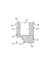
[0034]図1を参照すると、基板10は、キャリアヘッド100を有する化学的機械的研磨(CMP)装置によって研磨される。CMP装置の説明は、米国特許第5,738,574号に見つけることができ、特許の開示全体を本明細書に組み入れる。
Referring to FIG. 1, the
[0035]キャリアヘッド100は、ハウジング102と、ベースアセンブリ104と、(ベースアセンブリ104の一部と見なしてもよい)ジンバル機構106と、ローディングチャンバ108と、保持リング200と環状チャンバ350を提供するように形作られた第1のフレキシブル膜300とを含む保持リングアセンブリと、キャリアリング400と、複数の加圧可能なチャンバを画成する第2のフレキシブル膜500を含む基板裏当てアセンブリ110とを含む。同様のキャリアヘッドについて記載されたキャリアヘッドの他の特徴は、米国特許出願公開第2006/0154580号に見つけることができ、特許の開示全体を参照として本明細書に組み入れる。
[0035] The
[0036]ハウジング102は、一般的に、形状を円形とすることができ、ポリシング中に一緒に回転させるために、駆動軸に接続することができる。キャリアヘッド100の空気制御のために、ハウジング102を貫通して延びる流路(図示せず)があってもよい。ベースアセンブリ104は、ハウジング102の下に置かれた垂直方向に移動可能なアセンブリである。ジンバル機構106は、ベースアセンブリ104がハウジング102に対してジンバルすることを可能にすると共に、ハウジング102に対するベースアセンブリ104の横方向の動きを防止する。ローディングチャンバ108は、負荷、すなわち、下向の圧力又は重量をベースアセンブリ104に加えるために、ハウジング102とベースアセンブリ104との間に置かれている。研磨パッドに対するベースアセンブリ104の垂直方向位置も、ローディングチャンバ108によって制御される。基板裏当てアセンブリ110は、基板10のための取り付け面を提供することができる下面512を持つフレキシブル膜500を含む。
[0036] The
[0037]図2A〜図3Bを参照すると、基板10は、ベースアセンブリ104にクランプされた保持リングアセンブリによって支えることができる。保持リングアセンブリは、保持リング200と、環状チャンバ350を提供するように形作られたフレキシブル膜300とから構成することができる。保持リング200は、フレキシブル膜300の下に配置することができ、また、フレキシブル膜300に固着するように構成することができる。
[0037] Referring to FIGS. 2A-3B, the
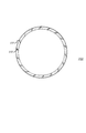
[0038]図2A〜図2Cに示すように、保持リング200は、内面231と下面232とを有する。内面231は、ポリシング中に、基板10のエッジを取り囲んで基板を保持するように構成することができる。保持リング200の下面232は、研磨パッドに接触させることができる。保持リング200は、2つの環状同心凹部233を有することができる環状上面を有する。環状同心凹部233は、保持リング200の上に配置されるフレキシブル膜300とかみ合うような大きさに寸法付けることができる。
[0038] As shown in FIGS. 2A-2C, the retaining
[0039]保持リング200は、2つのリング、すなわち、下環状部234と上環状部235とから構成することができる。下部234は、プラスチック、例えば、ポリフェニレンサルファイド(PPS)等の、CMPプロセスにおいて化学的に不活性である材料で形成することができる。また、下部は、耐久性があり、低摩耗率を有していなければならない。加えて、下部は、基板の保持リングに対する接触が、基板を欠損させたり、ひび割れさせたりしないように、十分に圧縮性でなければならない。一方、下部は、弾力性のために、保持リングに対する下向きの圧力が、下部を基板収容凹部中に押し出すことがないようにすべきである。保持リングの下部は、基板ローディングシステムの位置決め許容範囲に適合するように、基板の直径よりも少しだけ大きい、例えば、基板の直径よりも1〜2mm程度大きい内径を有することができる。保持リングは、約0.5インチの半径方向幅を有することができる。
[0039] The retaining
[0040]保持リング200の上部235は、下部234よりも硬い材料で形成することができる。硬い材料は、金属、例えば、ステンレス鋼、モリブデン、又はアルミニウム、あるいは、セラミック、例えば、アルミナ又は他の例示的な材料とすることができる。
[0040] The
[0041]保持リングの2つのリング234、235を合わせた場合、下部234の上面は、上部235の下面に隣接して配置される。2つのリングは、一般的に、2つのリング234、235が、合わされたときに2つのリング234、235が合わさる同一平面を形成するように、隣接する面上の内径及び外径において、実質的に同じ寸法を有する。
[0041] When the two
[0042]2つの環状部は、これらの隣接面の間に接合層236を取り付けることができる。2つのリングの間の接合層236は、スラリーの保持リング内への捕捉を防ぐことができる。接合層は、遅硬性又は速硬性エポキシ等の接着材料で作製することができる。接合層236の高温エポキシレジスト劣化は、ポリシングプロセス中の高熱による。特定の実施において、エポキシは、ポリアミド及び脂肪族アミンを含む。
[0042] The two annular portions may have a
[0043]上部235の上面は、保持リング200を保持リングの上に配置されたフレキシブル膜300に固着する、ボルト、ねじ又は他の金物類等の締結部材を収容するねじシース(図示しない)を有する円筒形凹部又はホール212を含むことができる。ホール212は、保持リングの周りに等間隔で離間させることができ、2つの環状同心凹部233の間に配置される。
[0043] The top surface of the
[0044]幾つかの実施において、保持リング200は、下面232内に形成された1つ以上のスラリー移送チャネル222を有する。スラリー移送チャネルは、ポリシング中にスラリーが、保持リングの外部から内部へ流れることができるようにするために、下部234の内径から外径へ延びている。スラリー移送チャネル222は、保持リングの周りに等間隔で離間させることができる。各スラリー移送チャネル222は、チャネルを通る半径に対して斜めに、例えば、45°オフセットすることができる。チャネルは、約0.125インチの幅を有することができる。
[0044] In some implementations, the retaining
[0045]幾つかの実施において、保持リング200は、流体、例えば、空気又は水が、ポリシング中に保持リングの内部から外部へ、又は、外部から内部へ流れることができるようにするために、保持リングの本体を貫通して内径から外径まで延びる1つ以上のスルーホールを有する。スルーホールは、上部235を貫通して延びることができる。スルーホールは、保持リングの周りに等間隔で離間させることができる。
[0045] In some implementations, the retaining
[0046]幾つかの実施において、保持リングの上部235は、その外面238に沿ってリップ部237を有することができる。リップ部は、水平下面と、垂直外面と、傾斜した非水平上面とを有することができる。リップ部237は、保持リングが基板ポリシング中に摩耗した際のキャリアリング400の上部内縁に対する保持リングのためのハードストップを提供することができる。
[0046] In some implementations, the
[0047]幾つかの実施において、上部235の外面238は、リップ部237の上に凹部246を形成することができる(リップ部の上の外面の部分は、リップ部の下の外面の部分に対して凹んでいる)。この凹部246は、チャンバ350が排気されるときに回転するように、フレキシブル膜300の側壁324のためのスペースを提供する。
[0047] In some implementations, the
[0048]幾つかの実施において、保持リングの上部235は、その下面において、その上面よりも幅を広くすることができる。例えば、内面231は、垂直領域242の下で上部から底部へ内方に傾斜した(すなわち、徐々に小さくなっていく直径を有する)テーパー状領域240を有することができる。テーパー状領域240は、上部235の下面に隣接することができる。下部234の内面は、垂直にすることができる。保持リングの下部が基板ポリシング中に摩耗する際、保持リングの上のより狭い内面は、基板取り付け面を提供する隣接するフレキシブル膜に対する摩耗を防ぐ。加えて、幾つかの実施において、保持リングの外面全体は、汚れがすぐに落ちるコーティング、例えば、パリレンで被覆することができる。
[0048] In some implementations, the retaining ring
[0049]図2Dに示す幾つかの実施において、下部234の上面は、上部235の下面内の対応する凹部内に延びる突出部244を有する。突出部244は、例えば、保持リングの周りに延びる環状とすることができ、また、段状部材を提供するために、保持リングの内面に配置することができる。接合層236は、突出部244の外側垂直壁に沿って延びることができる。動作中、この段状部材は、研磨パッドから下部234に対するせん断力を、突出部244の垂直壁230に対する側方力と、接合層236の関連する部分に対する圧縮力とに変換する。テーパー状領域240は、突出部244に隣接する上部235の一部として図示してあるが、テーパー状領域240は、下部234の一部とすることができ、例えば、突出部244の内面をテーパー状にすることができる。
[0049] In some implementations shown in FIG. 2D, the upper surface of the
[0050]保持リング200及びフレキシブル膜300は一緒になって保持リングアセンブリを形成する。フレキシブル膜300は、ベースアセンブリ104の上にクランプされ、環状保持リング200の下に固着されて、保持リングの上に環状チャンバ350を提供するように構成される。環状チャンバ350が加圧されると、フレキシブル膜は、保持リングに単独で制御可能な負荷を提供する。保持リングに対する負荷は、研磨パッドに負荷を提供する。保持リングに対して単独で負荷をかけることは、リングが摩耗する際に、パッド対して一貫した負荷をかけることを可能にすることができる。保持リングとキャリアヘッドとの間のフレキシブル膜の位置決めは、リングがキャリアヘッドに直接固着された場合に起きる保持リングに対するキャリアの変形の影響を低減する、又は排除することができる。このキャリアの変形の排除は、保持リングに対する一様でない摩耗を低減し、基板エッジにおけるプロセス変動を低減し、及びより低いポリシング圧力を使用できるようにし、リング寿命を延ばす。
[0050] The retaining
[0051]図3A、図3Bに示すように、フレキシブル膜300は、同心の内側及び外側側壁324を有する。フレキシブル膜300は、側壁324の上縁部から水平方向及び内方に延びる1組の環状リム部322を有することができる。フレキシブル膜は、フレキシブル膜の環状リム部322の下に配置されたクランプリングによってベースアセンブリ104にクランプすることができる。また、フレキシブル膜300は、下面を有する。フレキシブル膜の環状下面から下へ延びる2つの環状同心突出部326があってもよい。これらの環状同心突出部326は、フレキシブル膜の下に配置される保持リング200の上面において、環状同心凹部233に嵌合するような大きさに形成することができる。
[0051] As shown in FIGS. 3A and 3B, the
[0052]保持リングアセンブリのフレキシブル膜300は、弾性である材料で形成することができ、膜が加圧下で曲がることを可能にする。弾性材料は、シリコン及び他の例示的な材料を含むことができる。
[0052] The
[0053]フレキシブル膜の下面は、円形ホール312を含むことができる。円形ホール312は、2つの環状同心突出部326の間に配置することができ、また、フレキシブル膜の下面の周りに等間隔で離間させることができる。円形ホール312は、フレキシブル膜300を保持リング200に固着するための、ボルト、ねじ又は他の金物類等の締結部材を収容することができる。幾つかの実施においては、フレキシブル膜300を保持リング200に固着するために、接着剤、例えば、Loctiteが凹部212内に置かれ、ワンウェイねじが、フレキシブル膜300のホール312を通って収容凹部212内に挿入される。このようにして、フレキシブル膜300は、保持リング200に効果的に、恒久的に結合される。
[0053] The lower surface of the flexible membrane may include a
[0054]幾つかの実施において、フレキシブル膜300の同心の内側及び外側側壁324は、湾曲部328で下面を形成するために、下を包囲することができる。フレキシブル膜が保持リング200に固着されると、湾曲部328は、保持リングの上面の下に延びることができる。湾曲部328は、フレキシブル膜の底部が、側壁324の実質的な膨隆を伴うことなく、チャンバ350の加圧又は排気に応じて上下に動けるようにする回転ヒンジを提供する。幾つかの実施において、環状リム部322は、フレキシブル膜の側壁324よりも厚くすることができる。また、環状同心突出部326は、側壁324よりも厚くすることができる。
[0054] In some implementations, the concentric inner and
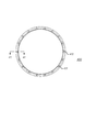
[0055]保持リング200は、基板10を保持し、かつ能動的なエッジプロセス制御を提供できるように構成されているが、キャリアリング400は、研磨パッドの表面に対するキャリアヘッドの位置決め又はリファレンシングを提供する。加えて、キャリアリング400は、保持リング200に接触し、保持リング200の横方向リファレンシングを提供できる。キャリアリング400は、保持リング200を取り囲むように構成できる。保持リングと同様に、キャリアリング400の下面433を研磨パッドに接触させることができる。
[0055] While the retaining
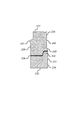
[0056]図4A〜図4Cに示すように、キャリアリング400は、環状上部431と環状下部432とを有することができる。上部431は、ベースアセンブリ104の下に配置することができ、また、その上面434の内径及び外径に沿って丸みのある部分を有することができる。保持リング200に接触する下部432の部分の内径は、保持リングの関連する部分の外径よりもわずかに大きく、保持リングの幅が約0.5インチである場合、キャリアリングの内径は、基板よりも約1インチ大きく、例えば、300mm(12インチ)基板の場合、内径は約13インチである。
As shown in FIGS. 4A-4C, the
[0057]下部432は、その外径440に沿って凹部441を有することができる。凹部441は、底面433から延びる垂直面422と、外径440から延びる水平面443と、垂直面442を水平面443に接続する傾斜面444とによって画成することができる。半径方向の断面に沿って測った場合の傾斜部の最も幅が広い部分は、傾斜面444の最も外側のエッジとすることができる。下部432は、外径440及び水平面443のエッジに沿った丸みのある部分を有することができる。
[0057] The
[0058]図4Dに示すように、幾つかの実施において、凹部441はさらに、外方へ突出する環状段部435bによって画成されている。環状段部435bは、水平下面と、傾斜面と、これらの2つの面のエッジに沿った丸みのある部分とを有することができる。下部432の半径方向断面で測った環状段部435bの最も幅が広い部分は、環状段部435bの最も外側のエッジとすることができる。
[0058] As shown in FIG. 4D, in some implementations, the
[0059]幾つかの実施においては、図4Cに示すように、キャリアリングは、下部432において内面430に沿って内方に突出する段部を有する。他の実施においては、図4Eに示すように、キャリアリングは、図4Eにおいて点線で表すように、キャリアリングの下面433に対して直角になってはいない内面430を有する(図4Eでは単一ピースのリングが図示されているが、傾斜した内面は、図4C及び図4Dに示すような2つの部分からなるリングにも適用できる)。内面430は、下面433に隣接する内面430の領域が傾斜した状態で、上部から底部まで外方に傾斜させることができる。内面の高い方の領域に対して(隆起した面又は傾斜した面に関わらず)下面433に隣接するより小さい方の内径は、キャリアリングが、保持リング200を横方向にリファレンシングできるようにし、キャリアリングが、基板のポリシング中に摩耗しても、保持リングとキャリアリングの間の接触位置において整合性を実現できる。加えて、キャリアリングの底部における部材の配置は、保持リングがキャリアリングに接触したときに、保持リングに回転力を与えることを防ぐことができる。幾つかの実施において、下部432の下面433は、上部431の上面434よりも小さい内径を有する。
[0059] In some implementations, the carrier ring has a step projecting inwardly along the
[0060]キャリアリングは、ベースアセンブリ104に取り付けることができる。一般的に、キャリアリングは、保持リング200を包囲し、かつ基板10のエッジに接触しないように構成される。キャリアリング400の上部431は、キャリアリング400をベースアセンブリ104に固着する、ボルト、ねじ、又は他の金物類等の締結部材を収容するねじシース(図示せず)を有する円筒形凹部又はホール412を含むことができる。ホール412は、キャリアリングの周りに等間隔で離間させることができる。幾つかの実施において、ホール412は、凹部441の水平面433の上に延びてはいない。例えば、図4Fに示すように、ホールは、平坦な下面433の上全体に配置することができる。また、アパーチャー又は突出部(図示せず)等の1つ以上のアラインメント部材を、上部431の上面434に配置することができる。キャリアリングがアラインメントアパーチャーを有する場合は、ベースアセンブリ104は、ベースアセンブリ104及びキャリアリングが正しく位置合わせされた場合に、アラインメントアパーチャーと一致する対応ピンを有することができる。
[0060] The carrier ring may be attached to the
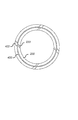
[0061]幾つかの実施において、キャリアリング400は、ポリシング中にスラリーが、キャリアリングの外部から内部へ流れることができるようにするために、下部432の内径から外径へ延びる1つ以上の貫通スラリー移送チャネル422を底面433上に有する。チャネル422は、キャリアリングの周りに等間隔で離間させることができる。各スラリー移送チャネル422は、チャネルを通る半径に対して斜めに、例えば、45°オフセットすることができる。図6を参照すると、キャリアリングチャネル422は、保持リングのチャネルと位置合わせすることができる。幾つかの実施形態において、キャリアリングチャネル422は、保持リングチャネル222よりも幅が広く、スラリーが保持リング200の内部に自由に流れることができるようになっている。例えば、キャリアリングチャネル422は、約0.25インチの幅を有することができる。
[0061] In some implementations, the
[0062]幾つかの実施において、キャリアリング400は、ポリシング中にスラリー又は空気が、キャリアリングの内部から外部へ、又は、外部から内部へ流れることができるようにするために、内径から外径へ延びる1つ以上のスルーホールを有する。スルーホールは、上部431を貫通して延びることができる。スルーホールは、キャリアリングの周りに等間隔で離間させることができる。幾つかの実施においては、キャリアリング内にはスルーホールがあるが、保持リング内にはスルーホールはない。従って、流体、例えば、キャリアリング内のスルーホールを通って噴霧される洗浄システムからの水は、保持リングの外側面に沿って下向きに流れ、その結果、キャリアリングと保持リングの間の空間を洗浄する。他の実施においては、キャリアリング内及び保持リング内の両方にスルーホールがあり、スルーホールは、流体が、キャリアリング及び保持リングの両方を通るように位置合わせされている。このような実施において、キャリアリング400を通るスルーホールは、保持リング200を通るスルーホールと同じか又はより幅広とすることができる。幾つかの実施において(図1参照)、スルーホール450は、キャリアリング自体を貫通してではなく、保持リングを包囲するハウジング102の一部を貫通して形成される。
[0062] In some implementations, the
[0063]図4A〜図4Cに戻って、幾つかの実施において、上部431は、その内面430に沿って内方突出するリップ部439を有することができ、リップ部は、垂直内壁と、その上及び下縁部に沿った丸みのある部分とを有する。突出するリップ部439は、段部432の内径以下の内径を有することができる。リップ部439は、リップ部237に係合して、保持リング200の過剰伸長を防ぐためのハードストップを提供することができる。幾つかの実施においては、図4Gに示すように、キャリアリング400は、傾斜した内面と、内方に突出するリップ部439の両方を含む。幾つかの実施においては、図4Hに示すように、キャリアリング400の内面は、下部432における内方に突出する段部と、底部から上部へ外側に傾斜している傾斜内面の両方を有する。
[0063] Returning to FIGS. 4A-4C, in some implementations, the
[0064]幾つかの実施においては、図4Cに示すように、キャリアリングの上部431と下部432は、異なる材料で形成される。上部431は、下部432よりも硬い材料で形成することができる。硬い材料は、金属、例えば、ステンレス鋼、モリブデン、又はアルミニウム、あるいはセラミック、例えばアルミナ、又は他の例示的な材料とすることができる。下部432は、プラスチック、例えば、ポリエーテルエーテルケトン(PEEK)、カーボン充填PEEK、Teflon(登録商標)充填PEEK、ポリアミドイミド(PAI)又は複合材料等の、CMPプロセスにおいて化学的に不活性である材料で形成することができる。
[0064] In some implementations, as shown in FIG. 4C, the upper and
[0065]キャリアリングの2つの部分431、432を結合すると、下部432の上面は、上部431の下面に隣接して配置される。2つの部分は、一般的に、結合されたときに、2つの部分431、432が、2つの部分431、432が合わさる箇所で同一平面を形成するように、これらの隣接する面上の内径及び外径において、実質的に同じ寸法を有する。2つの環状部は、これらの隣接する面間で接合層436によって取り付けることができる。
[0065] When the two
[0066]下部432は、段状部材438を有することができる。段状部材438は、下部432から、上部431の対応する凹部437内に垂直に突き出ている。段状部材438は、キャリアリング400の内径に隣接する環状段部である。段状部材438は、下リング432の水平部分から上へ延びている。段状部材438は、下リングの水平部分の内径を共有する。上部431における凹部437は、段状部材438に合致しているため、下部432と上部431とがくっつくと、段状部材438は、上部431の凹部437に嵌合する。凹部437は、水平上面と、丸みのある部分を有する垂直内壁とを有することができる。幾つかの実施において、ステップ438は、下リング432の内径にのみあり、外径にはない。すなわち、キャリアリング400は、キャリアリングの内径における段状部材438及び凹部437以外に他の段状部材及び対応する凹部437を有することはない。幾つかの実施において、接合層436は、キャリアリングの凹部437内の段状部材438の面まで延びていてもよい。
[0066] The
[0067]キャリアリングの回転中に発生したせん断力は、水平な接合層に力を及ぼす。キャリアリング400において、段状部材438は、せん断力を、段状部材438の垂直内壁に沿った接合層436に対する圧縮力に変換する。せん断力の、接合層436に対する圧縮力への変換は、段状部材を有しないキャリアリング内で起きる可能性のある、下部432の上部431からの剥離の可能性を低減する。また、キャリアリングが研磨パッドを押下した際の、キャリアリングの研磨パッドに対する水平方向の動きによって生じる側方力は、下部432から上部431のベースへ伝達される。加えて、垂直内壁は、境界における表面積の増加のため、接合層436に、より大きな接合面積を与える。また、より大きな接合面積は、下部432の上部431からの剥離の可能性を低減する。さらに、垂直内壁に沿った接合層436は、上部431の材料(例えば、ステンレス鋼等の硬い材料)と下部432の材料(例えば、PEEK複合材料等のより硬くない又はより柔軟な材料)との間の等しくない熱膨張からもたらされる応力を吸収する。
[0067] The shear force generated during rotation of the carrier ring exerts a force on the horizontal bonding layer. In the
[0068]幾つかの実施においては、例えば、図4E、図4G及び図4Hに示すように、キャリアリングの上部431及び下部432は、同じ材料で作製された単一のユニットを備える。単一構造のキャリアリングは、プラスチック、例えば、ポリエーテルエーテルケトン(PEEK)、カーボン充填PEEK、Teflon(登録商標)充填PEEK、ポリアミドイミド(PAI)又は複合材料等の、CMPプロセスにおいて化学的に不活性である材料で形成することができる。
[0068] In some implementations, for example, as shown in FIGS. 4E, 4G, and 4H, the
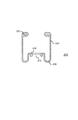
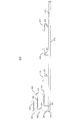
[0069]保持リング200は、基板10のエッジを取り囲んで基板を保持するように構成されているが、フレキシブル膜500は、基板10がマウントされる面512を提供する。図5は、フレキシブル膜500の部分断面図を示し、この概して対称的なフレキシブル膜の断面の半分のみを示す。
[0069] While the retaining
[0070]図5に示すように、フレキシブル膜500は、概して平坦な主部510と、外側環状部520とを有することができる。主部510は、基板取り付け面512を提供する。外側部520は、主部510の外縁部から延びている。主部510と外側環状部520との間の接合点は、周縁ヒンジ530と、外側環状部520の外壁に沿ってヒンジ530の上に配かれた環状凹部532とを有することができる。周縁ヒンジ530は、その内面及び外面に沿って、丸みのある部分を有することができる。周縁ヒンジ530及び環状凹部532は、適合するように構成することができ、基板10の周辺に対するローディングの対称性を改善する。
[0070] As shown in FIG. 5, the
[0071]外側環状部520は、その外壁に沿って環状凹部522を有することができ、環状凹部は、外側環状部520が曲がることができるように構成される。また、環状部520は、その内壁に沿って内方に突出する環状段部524を有することができる。環状段部524は、水平ではない(すなわち、傾斜している)上面及び下面を有することができる。
[0071] The outer
[0072]幾つかの実施において、フレキシブル膜500は、幾つかの環状フラップを有することができる。主部510は、4つの同心環状フラップ516を有することができる。外側環状部520は、1組の環状フラップ526を有することができる。外側環状部520に接続された環状フラップ526は、内方に延びて厚いリム部550を有する水平部540を有することができる。厚いリム部550は、ベースアセンブリ104に固着するように構成することができる。図5に示すように、上の環状フラップは、下の環状フラップよりも幅が狭い(すなわち、それほど延びていない)水平部を有することができる。幾つかの実施において、外側環状部520は、環状三角形状部を有することができ、また、1組の環状フラップ526の水平部540は、環状三角形状部の頂点を介して外側環状部520に接続することができる。
[0072] In some implementations, the
[0073]主部510に接続された最も内側の同心環状フラップ516は、ベースアセンブリ104に固着するように構成することができる、外方に延びて厚いリム部を有する水平部と、環状の角度のついた部分560とを含むことができる。環状の角度のついた部分560は、主部510と、環状フラップ516の水平部との間に結合することができる。環状の角度のついた部分560は、水平部との接合点においてよりも、主部510との接合点において、より大きな半径を有することができる。
[0073] The innermost concentric
[0074]主部510に接続された外側の3つの同心環状フラップ516は、主部510から延びる垂直部570と、水平部の外縁に沿った厚いリム部を有する、垂直部570から延びる水平部とを含むことができ、水平部は、ベースアセンブリ104に固着するように構成することができる。幾つかの実施形態において、同心環状フラップ516の水平部は、同心環状フラップの垂直部570よりも小さい厚みを有することができる。幾つかの実施において、第2及び第3の外側の同心環状フラップ516は、約1.5〜2.0、例えば、約1.66の水平部の長さと垂直部570の長さの比を有することができる。
[0074] The outer three concentric
[0075]幾つかの実施において、環状フラップ516、526は、1つ以上の凹み又は切り欠き(すなわち、環状凹部)を有することができる。同心環状フラップ516は、その水平部と、その垂直部570との間の接合点に切り欠き580を有することができる。切り欠き580は、同心環状フラップ516の水平部が垂直方向に曲がることを可能にする。同心環状フラップ516は、主部510との接合点において、切り欠き590を有することができる。切り欠き590は、主部510における圧縮を低減するように構成することができる。
[0075] In some implementations, the
[0076]本発明の別の態様においては、図1に示すように、CMP用キャリアヘッドは、ベースアセンブリ104と、ベースアセンブリ104の下に配置され、かつ基板10のエッジを取り囲んで基板を保持するように構成された環状保持リング200と、ベースアセンブリ104の下に、かつ環状保持リング200の上に配置された環状チャンバ350を提供するように形作られた第1のフレキシブル膜300と、保持リング200を取り囲むキャリアリング400と、基板取り付け面を提供する第2のフレキシブル膜500であって、ベースアセンブリ104と第2のフレキシブル膜500の間に生成された空間が、6つの加圧可能なチャンバを形成する第2のフレキシブル膜とを含むことができる。
[0076] In another aspect of the present invention, as shown in FIG. 1, a CMP carrier head is disposed below the
[0077]加圧可能なチャンバは、第2のフレキシブル膜500を、複数の同心クランプリングを用いてベースアセンブリ104にクランプすることによって形成することができる。チャンバは、最も内側のチャンバから最も外側のチャンバへ連続的に幅が狭くなるように構成することができる。周縁ヒンジ530によって部分的に画成される第2の外側のチャンバは、基板のポリシング中に、より良好なエッジ制御を提供できるように狭く構成される。
[0077] A pressurizable chamber can be formed by clamping the second
[0078]各チャンバは、ベースアセンブリ104及びハウジング102を通る流路(図示せず)によって、ポンプ又は圧力又は真空ライン等の関連する圧力源に流体的に結合することができる。第1のフレキシブル膜300の、環状チャンバ350のための1つの流路と、ローディングチャンバ108のための1つの流路と、全部で8つの流路の場合、ベースアセンブリ104と第2のフレキシブル膜500との間の6つの加圧可能なチャンバの各々のための1つの流路とがあってもよい。ベースアセンブリ104からの1つ以上の流路は、ローディングチャンバ108の内部又はキャリアヘッド100の外部に延びるフレキシブルチューブによって、ハウジング102内の流路につなぐことができる。各チャンバの加圧と、基板10上の、フレキシブル膜500の主部510の関連するセグメントによって加えられる力は、別々に制御することができる。このことは、ポリシング中に、異なる圧力を、基板の異なる半径方向領域に加えることを可能にし、それによって、不均一なポリシング速度を補正する。加えて、保持リング200に対する圧力は、チャンバ350を使用して膜500によって画成されるチャンバ内の圧力に無関係に変化することができ、また、キャリアリング400に対する圧力は、保持リング200に対する圧力と、ローディングチャンバ108を使用して膜500によって画成されるチャンバ内の圧力とに関連して変化することができる。
[0078] Each chamber, by flow path through the
[0079]上述したような保持リング200、第1のフレキシブル膜300、キャリアリング400、第2のフレキシブル膜500からなる多数の実施形態を、上記キャリアヘッドに実装することができる。
[0079] Numerous embodiments of the retaining
[0080]一般的に、キャリアヘッドは、ベースアセンブリ104に接続され、かつ駆動軸に固着されるように構成されたハウジング102をさらに備えることができる。キャリアヘッドは、材料、例えば、アルミニウム、PEEK又は複合材料で被覆することができる。キャリアヘッドのキャリアリング400は、下向きの圧力を研磨パッドに加えることができる。幾つかの実施形態において、キャリアリング400によって加えられる下向きの圧力は、保持リング200によって加えられる下向きの圧力よりも大きい。キャリアリング400は、保持リング200よりも硬い材料で形成することができ、保持リングよりも遅い速度で摩耗するキャリアリングをもたらす。保持リング200及びキャリアリング300の幅は、プロセス結果を調節するために変えることができる。具体的には、基板エッジ上のポリシングプロファイルは、各リングに対する幅及び圧力を変化させることによって変更することができる。
[0080] In general, the carrier head may further comprise a
[0081]幾つかの実施形態において、保持リング200は、図1において点線で表すように、保持リング200の内面231から外面238に延びて、流体が、リングの内部から外部へ、又は外部から内部へ流れることを可能にするスロット又はスルーホールを有することができる。これらのスロットは、キャリアヘッド100内のスロットと位置合わせすることができ、また、保持リング200の内部からの過剰なスラリーを洗い流す手段を提供することができる。
[0081] In some embodiments, the retaining
[0082]幾つかの実施においては、第2のフレキシブル膜500の同心環状フラップ516内に切り欠き580、590を有することによって、ポリシングの均一性を改善することができる。切り欠きの可能性のある効果は、隣接するチャンバに同じでない圧力が存在する場合に、ポリシング均一性を改善することである。具体的には、隣接するチャンバに同じでない圧力が存在する場合、高い圧力のチャンバ内の圧力は、分離フラップを低い圧力のチャンバ内へたわませる傾向がある。分離フラップのこのたわみは、分離フラップに隣接する主部510における圧縮領域を招く可能性があり、意図せぬ圧力配分及び不均一なポリシングをもたらす。しかし、主部510と垂直部570の間の接合部に切り欠き590を有することが、環状フラップ516を接合部において、よりフレキシブルにする。このことは、フラップが同じでない圧力によって曲がった場合の主部510における圧縮を低減し、それによってポリシング均一性を改善する。切り欠き590は、同心環状フラップ516の両側の隣接する加圧可能なチャンバにおいて、圧力が同じでない場合に、同心環状フラップ516が曲がることを可能にするように適合させることができる。さらに、切り欠き580、590は、主部510における圧縮を低減するために、少なくとも1つの加圧可能なチャンバから同心環状フラップ516を介して主部510に伝わる下向きの負荷を低減するように配置しかつ構成することができる。
[0082] In some implementations, having the
[0083]本発明の多数の実施形態について説明してきた。それでもなお、本発明の趣旨及び範囲から逸脱することなく、様々な変更を行うことができることが理解されるであろう。例えば、上記第2のフレキシブル膜の同心環状フラップ216のうちの幾つかは、環状垂直部570の代わりに、環状の角度のついた部分560を有することができる。加えて、上記切り欠きは、環状の角度のついた部分560との接合点における、又は、水平部540と周縁550との間の接合点における垂直部570の中間に設けてもよい。従って、他の実施も、以下のクレームの範囲内にある。
[0083] A number of embodiments of the invention have been described. Nevertheless, it will be understood that various modifications can be made without departing from the spirit and scope of the invention. For example, some of the second flexible membrane concentric annular flaps 216 may have an annular
10…基板、100…キャリアヘッド、102…ハウジング、104…ベースアセンブリ、200…保持リング、300…第1のフレキシブル膜、350…環状チャンバ、400…キャリアリング、500…第2のフレキシブル膜。
DESCRIPTION OF
Claims (15)
研磨パッドに接触するように構成された下面と、
前記キャリアヘッドに取り付けられるように構成された上面とを有する環状リングを備え、
前記内面が、前記下面に隣接して内方へ突出した段部を含み、前記内方へ突出した段部が、前記キャリアヘッドの前記保持リングより低い高さを有し、前記内方へ突出した段部が、前記内面の第1の領域を提供し、
前記第1の領域に隣接し、かつ前記第1の領域の上の前記内面の第2の領域よりも小さい内径を有する前記下面に、前記第1の領域が隣接し、
前記第1の領域が、前記保持リングの横方向リファレンシングを提供し、前記保持リングに回転力を与えることを防ぐように構成されている、キャリアリング。 An inner surface contained within the carrier head and configured to surround a retaining ring that surrounds and holds the substrate edge during polishing ;
A lower surface configured to contact the polishing pad;
An annular ring having a configured top surface to be attached to the carrier head,
The inner surface includes an inwardly protruding step adjacent to the lower surface, and the inwardly protruding step has a lower height than the retaining ring of the carrier head and protrudes inward. A stepped portion provides a first region of the inner surface;
The first adjacent regions, and the lower surface having a second inner diameter smaller than the area of said inner surface on said first region, said first region is adjacent,
A carrier ring, wherein the first region is configured to provide lateral referencing of the retaining ring to prevent imparting rotational force to the retaining ring.
Applications Claiming Priority (6)
| Application Number | Priority Date | Filing Date | Title |
|---|---|---|---|
| US86709006P | 2006-11-22 | 2006-11-22 | |
| US60/867,090 | 2006-11-22 | ||
| US89170507P | 2007-02-26 | 2007-02-26 | |
| US60/891,705 | 2007-02-26 | ||
| US11/741,677 | 2007-04-27 | ||
| US11/741,677 US7699688B2 (en) | 2006-11-22 | 2007-04-27 | Carrier ring for carrier head |
Publications (2)
| Publication Number | Publication Date |
|---|---|
| JP2008131049A JP2008131049A (en) | 2008-06-05 |
| JP5324775B2 true JP5324775B2 (en) | 2013-10-23 |
Family
ID=38982669
Family Applications (1)
| Application Number | Title | Priority Date | Filing Date |
|---|---|---|---|
| JP2007298304A Active JP5324775B2 (en) | 2006-11-22 | 2007-11-16 | Carrier ring for carrier head |
Country Status (7)
| Country | Link |
|---|---|
| US (2) | US7699688B2 (en) |
| EP (1) | EP1925400B1 (en) |
| JP (1) | JP5324775B2 (en) |
| KR (1) | KR100942624B1 (en) |
| CN (1) | CN101293333B (en) |
| SG (1) | SG143189A1 (en) |
| TW (2) | TWI430870B (en) |
Cited By (1)
| Publication number | Priority date | Publication date | Assignee | Title |
|---|---|---|---|---|
| KR20160000054A (en) * | 2014-06-23 | 2016-01-04 | 삼성전자주식회사 | Carrier head, chemical mechanical polishing apparatus and wafer polishing method |
Families Citing this family (37)
| Publication number | Priority date | Publication date | Assignee | Title |
|---|---|---|---|---|
| KR101011788B1 (en) | 2004-11-01 | 2011-02-07 | 가부시키가이샤 에바라 세이사꾸쇼 | Top ring, polishing apparatus and polishing method |
| US7727055B2 (en) * | 2006-11-22 | 2010-06-01 | Applied Materials, Inc. | Flexible membrane for carrier head |
| US7654888B2 (en) * | 2006-11-22 | 2010-02-02 | Applied Materials, Inc. | Carrier head with retaining ring and carrier ring |
| US7699688B2 (en) * | 2006-11-22 | 2010-04-20 | Applied Materials, Inc. | Carrier ring for carrier head |
| KR101617716B1 (en) * | 2008-03-25 | 2016-05-03 | 어플라이드 머티어리얼스, 인코포레이티드 | Improved carrier head membrane |
| US7749052B2 (en) * | 2008-09-08 | 2010-07-06 | Applied Materials, Inc. | Carrier head using flexure restraints for retaining ring alignment |
| US8475231B2 (en) | 2008-12-12 | 2013-07-02 | Applied Materials, Inc. | Carrier head membrane |
| JP5392483B2 (en) * | 2009-08-31 | 2014-01-22 | 不二越機械工業株式会社 | Polishing equipment |
| TWI574785B (en) | 2010-08-06 | 2017-03-21 | 應用材料股份有限公司 | Inner retaining ring and outer retaining ring |
| CN102172886B (en) * | 2011-02-16 | 2013-01-16 | 清华大学 | Polishing head |
| US8774958B2 (en) | 2011-04-29 | 2014-07-08 | Applied Materials, Inc. | Selection of polishing parameters to generate removal profile |
| US10052739B2 (en) * | 2011-09-12 | 2018-08-21 | Applied Materials, Inc. | Carrier head with composite plastic portions |
| US9017138B2 (en) | 2012-01-25 | 2015-04-28 | Applied Materials, Inc. | Retaining ring monitoring and control of pressure |
| US9050700B2 (en) * | 2012-01-27 | 2015-06-09 | Applied Materials, Inc. | Methods and apparatus for an improved polishing head retaining ring |
| WO2013134075A1 (en) | 2012-03-08 | 2013-09-12 | Applied Materials, Inc. | Detecting membrane breakage in a carrier head |
| KR20130131120A (en) * | 2012-05-23 | 2013-12-03 | 삼성전자주식회사 | A flexible membrane for polishing head |
| KR20150085000A (en) | 2012-11-16 | 2015-07-22 | 어플라이드 머티어리얼스, 인코포레이티드 | Recording measurements by sensors for a carrier head |
| US10532441B2 (en) * | 2012-11-30 | 2020-01-14 | Applied Materials, Inc. | Three-zone carrier head and flexible membrane |
| WO2014163735A1 (en) | 2013-03-13 | 2014-10-09 | Applied Materials, Inc. | Reinforcement ring for carrier head |
| US20140273756A1 (en) * | 2013-03-14 | 2014-09-18 | Chih Hung Chen | Substrate precession mechanism for cmp polishing head |
| US10252397B2 (en) * | 2014-10-30 | 2019-04-09 | Applied Materials, Inc. | Methods and apparatus for profile and surface preparation of retaining rings utilized in chemical mechanical polishing processes |
| JP6392193B2 (en) * | 2015-10-14 | 2018-09-19 | 株式会社荏原製作所 | Substrate holding device, substrate polishing device, and method of manufacturing substrate holding device |
| US10029346B2 (en) * | 2015-10-16 | 2018-07-24 | Applied Materials, Inc. | External clamp ring for a chemical mechanical polishing carrier head |
| US10160091B2 (en) | 2015-11-16 | 2018-12-25 | Taiwan Semiconductor Manufacturing Company, Ltd. | CMP polishing head design for improving removal rate uniformity |
| USD839224S1 (en) * | 2016-12-12 | 2019-01-29 | Ebara Corporation | Elastic membrane for semiconductor wafer polishing |
| CN108573887B (en) * | 2017-03-09 | 2021-02-09 | 台湾积体电路制造股份有限公司 | Support carrier, leak testing system and method |
| CN107378745A (en) * | 2017-08-31 | 2017-11-24 | 覃幼洁 | A kind of thin-walled cylinder sleeve honing fixture that can reduce pinching deformation |
| CN107457686A (en) * | 2017-08-31 | 2017-12-12 | 覃幼洁 | A kind of cylinder sleeve honing fixture that can reduce pinching deformation |
| KR102637832B1 (en) * | 2018-11-09 | 2024-02-19 | 주식회사 케이씨텍 | Carrier head of chemical mechanical apparatus and membrane used therein |
| CN110076694A (en) * | 2019-05-20 | 2019-08-02 | 江苏欣颍新材料科技有限公司 | A kind of burnishing device of billiard ball production |
| US11945073B2 (en) | 2019-08-22 | 2024-04-02 | Applied Materials, Inc. | Dual membrane carrier head for chemical mechanical polishing |
| CN111482893A (en) * | 2020-04-16 | 2020-08-04 | 华海清科股份有限公司 | Chemical mechanical polishing retaining ring and chemical mechanical polishing bearing head |
| KR20220116322A (en) | 2020-07-08 | 2022-08-22 | 어플라이드 머티어리얼스, 인코포레이티드 | Multi-toothed, self-regulating retaining ring |
| KR20230023756A (en) | 2021-03-05 | 2023-02-17 | 어플라이드 머티어리얼스, 인코포레이티드 | Control of process parameters using cost function or expected future parameter changes during substrate polishing |
| US20220283554A1 (en) | 2021-03-05 | 2022-09-08 | Applied Materials, Inc. | Control of processing parameters for substrate polishing with substrate precession |
| US20230023915A1 (en) * | 2021-07-21 | 2023-01-26 | Applied Materials, Inc. | Interlocked stepped retaining ring |
| TWI791305B (en) * | 2021-10-18 | 2023-02-01 | 尚源股份有限公司 | Wafer Grinding Embedded Structure |
Family Cites Families (48)
| Publication number | Priority date | Publication date | Assignee | Title |
|---|---|---|---|---|
| JP3158934B2 (en) * | 1995-02-28 | 2001-04-23 | 三菱マテリアル株式会社 | Wafer polishing equipment |
| US5738574A (en) | 1995-10-27 | 1998-04-14 | Applied Materials, Inc. | Continuous processing system for chemical mechanical polishing |
| KR100485002B1 (en) * | 1996-02-16 | 2005-08-29 | 가부시키가이샤 에바라 세이사꾸쇼 | Workpiece polishing apparatus and method |
| US6183354B1 (en) * | 1996-11-08 | 2001-02-06 | Applied Materials, Inc. | Carrier head with a flexible membrane for a chemical mechanical polishing system |
| US6056632A (en) * | 1997-02-13 | 2000-05-02 | Speedfam-Ipec Corp. | Semiconductor wafer polishing apparatus with a variable polishing force wafer carrier head |
| US6019670A (en) * | 1997-03-10 | 2000-02-01 | Applied Materials, Inc. | Method and apparatus for conditioning a polishing pad in a chemical mechanical polishing system |
| US5964653A (en) * | 1997-07-11 | 1999-10-12 | Applied Materials, Inc. | Carrier head with a flexible membrane for a chemical mechanical polishing system |
| US5916015A (en) | 1997-07-25 | 1999-06-29 | Speedfam Corporation | Wafer carrier for semiconductor wafer polishing machine |
| US6116992A (en) * | 1997-12-30 | 2000-09-12 | Applied Materials, Inc. | Substrate retaining ring |
| WO1999048645A1 (en) * | 1998-03-23 | 1999-09-30 | Speedfam-Ipec Corporation | Backing pad for workpiece carrier |
| JP3966908B2 (en) | 1998-04-06 | 2007-08-29 | 株式会社荏原製作所 | Polishing device |
| US6143127A (en) * | 1998-05-14 | 2000-11-07 | Applied Materials, Inc. | Carrier head with a retaining ring for a chemical mechanical polishing system |
| US6436228B1 (en) * | 1998-05-15 | 2002-08-20 | Applied Materials, Inc. | Substrate retainer |
| US6251215B1 (en) * | 1998-06-03 | 2001-06-26 | Applied Materials, Inc. | Carrier head with a multilayer retaining ring for chemical mechanical polishing |
| JP2000052239A (en) * | 1998-07-31 | 2000-02-22 | Mitsubishi Materials Corp | Wafer polishing device |
| US6244942B1 (en) * | 1998-10-09 | 2001-06-12 | Applied Materials, Inc. | Carrier head with a flexible membrane and adjustable edge pressure |
| US6089961A (en) * | 1998-12-07 | 2000-07-18 | Speedfam-Ipec Corporation | Wafer polishing carrier and ring extension therefor |
| US6143354A (en) * | 1999-02-08 | 2000-11-07 | Medtronic Inc. | One-step method for attachment of biomolecules to substrate surfaces |
| US20020173242A1 (en) * | 1999-04-19 | 2002-11-21 | Mitsubishi Materials Corporation | Chemical mechanical polishing head assembly having floating wafer carrier and retaining ring |
| US6068549A (en) * | 1999-06-28 | 2000-05-30 | Mitsubishi Materials Corporation | Structure and method for three chamber CMP polishing head |
| US6186880B1 (en) * | 1999-09-29 | 2001-02-13 | Semiconductor Equipment Technology | Recyclable retaining ring assembly for a chemical mechanical polishing apparatus |
| EP1092504B1 (en) | 1999-10-15 | 2005-12-07 | Ebara Corporation | Apparatus and method for polishing workpiece |
| US6663466B2 (en) * | 1999-11-17 | 2003-12-16 | Applied Materials, Inc. | Carrier head with a substrate detector |
| US6450868B1 (en) * | 2000-03-27 | 2002-09-17 | Applied Materials, Inc. | Carrier head with multi-part flexible membrane |
| US6722965B2 (en) * | 2000-07-11 | 2004-04-20 | Applied Materials Inc. | Carrier head with flexible membranes to provide controllable pressure and loading area |
| US7101273B2 (en) * | 2000-07-25 | 2006-09-05 | Applied Materials, Inc. | Carrier head with gimbal mechanism |
| US7198561B2 (en) * | 2000-07-25 | 2007-04-03 | Applied Materials, Inc. | Flexible membrane for multi-chamber carrier head |
| US6857945B1 (en) * | 2000-07-25 | 2005-02-22 | Applied Materials, Inc. | Multi-chamber carrier head with a flexible membrane |
| US6419567B1 (en) * | 2000-08-14 | 2002-07-16 | Semiconductor 300 Gmbh & Co. Kg | Retaining ring for chemical-mechanical polishing (CMP) head, polishing apparatus, slurry cycle system, and method |
| US7137874B1 (en) * | 2000-11-21 | 2006-11-21 | Memc Electronic Materials, Spa | Semiconductor wafer, polishing apparatus and method |
| CN1148798C (en) * | 2001-03-28 | 2004-05-05 | 矽统科技股份有限公司 | Locating ring for chip carrier |
| KR100470227B1 (en) | 2001-06-07 | 2005-02-05 | 두산디앤디 주식회사 | Carrier Head for Chemical Mechanical Polishing |
| US6890249B1 (en) * | 2001-12-27 | 2005-05-10 | Applied Materials, Inc. | Carrier head with edge load retaining ring |
| US6872130B1 (en) * | 2001-12-28 | 2005-03-29 | Applied Materials Inc. | Carrier head with non-contact retainer |
| TWM255104U (en) * | 2003-02-05 | 2005-01-11 | Applied Materials Inc | Retaining ring with flange for chemical mechanical polishing |
| JP2005011999A (en) * | 2003-06-19 | 2005-01-13 | Tokyo Seimitsu Co Ltd | Workpiece holding head and polishing apparatus having the same |
| JP5296985B2 (en) * | 2003-11-13 | 2013-09-25 | アプライド マテリアルズ インコーポレイテッド | Retaining ring with shaping surface |
| JP4583207B2 (en) * | 2004-03-31 | 2010-11-17 | 不二越機械工業株式会社 | Polishing equipment |
| JP4822744B2 (en) * | 2004-06-04 | 2011-11-24 | 三星電子株式会社 | Chemical mechanical polishing equipment, carrier head and compartment ring |
| US7081042B2 (en) * | 2004-07-22 | 2006-07-25 | Applied Materials | Substrate removal from polishing tool |
| JP4597634B2 (en) * | 2004-11-01 | 2010-12-15 | 株式会社荏原製作所 | Top ring, substrate polishing apparatus and polishing method |
| KR101011788B1 (en) | 2004-11-01 | 2011-02-07 | 가부시키가이샤 에바라 세이사꾸쇼 | Top ring, polishing apparatus and polishing method |
| JP2006324413A (en) * | 2005-05-18 | 2006-11-30 | Ebara Corp | Substrate retaining device and polishing device |
| US7101272B2 (en) * | 2005-01-15 | 2006-09-05 | Applied Materials, Inc. | Carrier head for thermal drift compensation |
| US7052374B1 (en) * | 2005-03-01 | 2006-05-30 | Taiwan Semiconductor Manufacturing Co., Ltd. | Multipurpose slurry delivery arm for chemical mechanical polishing |
| JP2007007747A (en) * | 2005-06-28 | 2007-01-18 | Nitta Haas Inc | Retainer for matter to be polished and polishing head |
| US7654888B2 (en) | 2006-11-22 | 2010-02-02 | Applied Materials, Inc. | Carrier head with retaining ring and carrier ring |
| US7699688B2 (en) | 2006-11-22 | 2010-04-20 | Applied Materials, Inc. | Carrier ring for carrier head |
-
2007
- 2007-04-27 US US11/741,677 patent/US7699688B2/en active Active
- 2007-10-26 KR KR1020070108344A patent/KR100942624B1/en active IP Right Grant
- 2007-11-16 JP JP2007298304A patent/JP5324775B2/en active Active
- 2007-11-19 EP EP07022414A patent/EP1925400B1/en active Active
- 2007-11-21 TW TW096144179A patent/TWI430870B/en active
- 2007-11-21 SG SG200717954-2A patent/SG143189A1/en unknown
- 2007-11-21 TW TW102143866A patent/TWI554360B/en active
- 2007-11-22 CN CN2007101655960A patent/CN101293333B/en active Active
-
2010
- 2010-02-02 US US12/698,912 patent/US7901273B2/en active Active
Cited By (2)
| Publication number | Priority date | Publication date | Assignee | Title |
|---|---|---|---|---|
| KR20160000054A (en) * | 2014-06-23 | 2016-01-04 | 삼성전자주식회사 | Carrier head, chemical mechanical polishing apparatus and wafer polishing method |
| KR102173323B1 (en) * | 2014-06-23 | 2020-11-04 | 삼성전자주식회사 | Carrier head, chemical mechanical polishing apparatus and wafer polishing method |
Also Published As
| Publication number | Publication date |
|---|---|
| JP2008131049A (en) | 2008-06-05 |
| SG143189A1 (en) | 2008-06-27 |
| EP1925400A1 (en) | 2008-05-28 |
| KR100942624B1 (en) | 2010-02-17 |
| KR20080046555A (en) | 2008-05-27 |
| TW201414572A (en) | 2014-04-16 |
| CN101293333A (en) | 2008-10-29 |
| US20100151777A1 (en) | 2010-06-17 |
| CN101293333B (en) | 2010-12-08 |
| US20080119119A1 (en) | 2008-05-22 |
| US7699688B2 (en) | 2010-04-20 |
| TWI430870B (en) | 2014-03-21 |
| TW200833463A (en) | 2008-08-16 |
| TWI554360B (en) | 2016-10-21 |
| US7901273B2 (en) | 2011-03-08 |
| EP1925400B1 (en) | 2012-06-06 |
Similar Documents
| Publication | Publication Date | Title |
|---|---|---|
| JP5324775B2 (en) | Carrier ring for carrier head | |
| JP5314267B2 (en) | Retaining ring, flexible membrane for applying load to retaining ring, and retaining ring assembly | |
| JP5250243B2 (en) | Flexible film for carrier head | |
| JP5329071B2 (en) | Carrier head with retaining ring and carrier ring | |
| TWI574785B (en) | Inner retaining ring and outer retaining ring |
Legal Events
| Date | Code | Title | Description |
|---|---|---|---|
| A621 | Written request for application examination |
Free format text: JAPANESE INTERMEDIATE CODE: A621 Effective date: 20101013 |
|
| RD03 | Notification of appointment of power of attorney |
Free format text: JAPANESE INTERMEDIATE CODE: A7423 Effective date: 20101105 |
|
| RD04 | Notification of resignation of power of attorney |
Free format text: JAPANESE INTERMEDIATE CODE: A7424 Effective date: 20101209 |
|
| A131 | Notification of reasons for refusal |
Free format text: JAPANESE INTERMEDIATE CODE: A131 Effective date: 20120802 |
|
| RD04 | Notification of resignation of power of attorney |
Free format text: JAPANESE INTERMEDIATE CODE: A7424 Effective date: 20120925 |
|
| A601 | Written request for extension of time |
Free format text: JAPANESE INTERMEDIATE CODE: A601 Effective date: 20121102 |
|
| A602 | Written permission of extension of time |
Free format text: JAPANESE INTERMEDIATE CODE: A602 Effective date: 20121107 |
|
| A601 | Written request for extension of time |
Free format text: JAPANESE INTERMEDIATE CODE: A601 Effective date: 20121203 |
|
| A602 | Written permission of extension of time |
Free format text: JAPANESE INTERMEDIATE CODE: A602 Effective date: 20121206 |
|
| A521 | Request for written amendment filed |
Free format text: JAPANESE INTERMEDIATE CODE: A523 Effective date: 20130104 |
|
| TRDD | Decision of grant or rejection written | ||
| A01 | Written decision to grant a patent or to grant a registration (utility model) |
Free format text: JAPANESE INTERMEDIATE CODE: A01 Effective date: 20130619 |
|
| A61 | First payment of annual fees (during grant procedure) |
Free format text: JAPANESE INTERMEDIATE CODE: A61 Effective date: 20130719 |
|
| R150 | Certificate of patent or registration of utility model |
Ref document number: 5324775 Country of ref document: JP Free format text: JAPANESE INTERMEDIATE CODE: R150 Free format text: JAPANESE INTERMEDIATE CODE: R150 |
|
| R250 | Receipt of annual fees |
Free format text: JAPANESE INTERMEDIATE CODE: R250 |
|
| R250 | Receipt of annual fees |
Free format text: JAPANESE INTERMEDIATE CODE: R250 |
|
| R250 | Receipt of annual fees |
Free format text: JAPANESE INTERMEDIATE CODE: R250 |
|
| R250 | Receipt of annual fees |
Free format text: JAPANESE INTERMEDIATE CODE: R250 |
|
| R250 | Receipt of annual fees |
Free format text: JAPANESE INTERMEDIATE CODE: R250 |
|
| R250 | Receipt of annual fees |
Free format text: JAPANESE INTERMEDIATE CODE: R250 |
|
| R250 | Receipt of annual fees |
Free format text: JAPANESE INTERMEDIATE CODE: R250 |
|
| R250 | Receipt of annual fees |
Free format text: JAPANESE INTERMEDIATE CODE: R250 |