JP5322016B2 - Single screw multistage compressor and refrigeration / cooling system using the same - Google Patents
Single screw multistage compressor and refrigeration / cooling system using the same Download PDFInfo
- Publication number
- JP5322016B2 JP5322016B2 JP2012007415A JP2012007415A JP5322016B2 JP 5322016 B2 JP5322016 B2 JP 5322016B2 JP 2012007415 A JP2012007415 A JP 2012007415A JP 2012007415 A JP2012007415 A JP 2012007415A JP 5322016 B2 JP5322016 B2 JP 5322016B2
- Authority
- JP
- Japan
- Prior art keywords
- stage
- low
- stage compressor
- economizer
- compressor
- Prior art date
- Legal status (The legal status is an assumption and is not a legal conclusion. Google has not performed a legal analysis and makes no representation as to the accuracy of the status listed.)
- Active
Links
Images


Abstract
Description
本発明は、同一芯を有する軸上に構成され1台のモータによって駆動される所謂単機多段スクリュー圧縮機に関し、特に、低段圧縮機にエコノマイザー冷却器が接続されるとともに高低段圧縮機の理論風量比(押しのけ量比)を従来の低段圧縮機にエコノマイザーが接続されない場合よりも大きく設定した多段スクリュー圧縮機、および該多段スクリュー圧縮機を用いて構成される冷凍・冷却システムに関する。 The present invention relates to a so-called single-unit multi-stage screw compressor configured on a shaft having the same core and driven by a single motor, and in particular, an economizer cooler is connected to the low-stage compressor and the high-low stage compressor is The present invention relates to a multistage screw compressor in which a theoretical air volume ratio (displacement ratio) is set larger than that in the case where an economizer is not connected to a conventional low stage compressor, and a refrigeration / cooling system configured using the multistage screw compressor.
より低い冷凍温度を得るために、食品冷凍、真空凍結乾燥、プロセス冷却等の用途に2段圧縮機構が用いられている。また、小型、軽量化の点からこれら2段圧縮機が一体化したいわゆる単機構造の圧縮機が用いられている。例えば、2段スクリュー圧縮機を駆動モータとともに一体に組み合わせた単機多段スクリュー圧縮機が知られており、この単機多段スクリュー圧縮機については種々の提案がされている。 In order to obtain a lower freezing temperature, a two-stage compression mechanism is used for food freezing, vacuum freeze drying, process cooling, and the like. In addition, a so-called single-unit compressor in which these two-stage compressors are integrated is used from the viewpoint of miniaturization and weight reduction. For example, a single-machine multi-stage screw compressor in which a two-stage screw compressor is integrally combined with a drive motor is known, and various proposals have been made for this single-machine multi-stage screw compressor.
例えば、特許文献1(特許第2781523号公報)には、冷凍装置に用いられる2段式スクリュー圧縮機に関する発明が示されており、そこには、1段圧縮機の雌雄スクリューロータの歯数を5(雄側)、6(雌側)とし、2段圧縮機の雌雄スクリューロータの歯数を4(雄側)、6(雌側)として、第1段と第2段との吐出脈動周波数を異ならせて騒音低減を図る技術が示されている。 For example, Patent Document 1 (Japanese Patent No. 2781523) discloses an invention relating to a two-stage screw compressor used in a refrigeration apparatus, in which the number of teeth of a male and female screw rotor of a single-stage compressor is indicated. 5 (male side) and 6 (female side), and the number of teeth of the male and female screw rotors of the two-stage compressor is 4 (male side) and 6 (female side). A technique for reducing noise by differentiating the noise is shown.
また、多段圧縮機の成績係数(以下COPという)を向上させるために、圧縮機にエコノマイザー回路を付加することが行われていて、例えば特許文献2(特開2006−258397号公報)には、図10に示すように、低段側圧縮機01と高段側圧縮機02とが直列に接続された多段圧縮機03について、複数の圧縮機の圧縮比を等しくなるように吸込み体積を制御すると共に、低段エコノマイザー回路04、高段エコノマイザー回路05を低段側圧縮機01、高段側圧縮機02にそれぞれ接続し、さらに中間冷却器06が設けられる技術が示されている。
In order to improve the coefficient of performance (hereinafter referred to as COP) of a multistage compressor, an economizer circuit is added to the compressor. For example, Patent Document 2 (Japanese Patent Application Laid-Open No. 2006-258397) discloses that As shown in FIG. 10, the suction volume is controlled so that the compression ratios of a plurality of compressors are equal in a
また、特許文献3(特開2005−83260号公報)には、多段でないが単段のスクリュー式圧縮機において、図11に示すように、エコノマイザーポート010からスクリュー圧縮機011に効率よく冷媒を供給するためのポート形状について示されており、そこには、エコノマイザーポート010がスクリューロータ012の羽根013の長さ方向に沿って形成されることが示されている。
Further, in Patent Document 3 (Japanese Patent Laid-Open No. 2005-83260), in a single-stage screw type compressor that is not multistage, as shown in FIG. 11, refrigerant is efficiently supplied from the
しかし、前記特許文献1に示される2段形スクリュー圧縮機は、1段圧縮機と2段圧縮機と駆動モータとを直列に一体に組立てられる構造が示されているが、1段圧縮機の雌雄スクリューロータの歯数の組み合わせと2段圧縮機の雌雄スクリューロータの歯数の組み合わせとを異ならせて振動騒音を抑える技術であり、圧縮機の高効率化とともに2段スクリュー圧縮機を用いた冷凍機の冷凍能力を、エコマイザー効果によって高める技術については示されていない。
However, the two-stage screw compressor disclosed in
また、前記特許文献2には、低段エコノマイザー回路04、高段エコノマイザー回路05を低段側圧縮機01、高段側圧縮機02にそれぞれ接続してエコマイザー効果による冷凍能力の向上について示されているが、この特許文献2の技術は、複数の圧縮機の圧縮比が等しくなるように吸込み体積を制御するものであり、高低段側圧縮機の風量比(押しのけ量比)を大きくして高圧縮比にして、低段側圧縮機のエコノマイザー効果を高めて冷凍能力を高めるとともに、高段側圧縮機を小容量化することについては示されていない。
また、エコノマイザーポートの具体的な設置構造の開示はなく実用的な構造までは示されていない。
Further, in Patent Document 2, a low-
Further, there is no disclosure of a specific installation structure of the economizer port, and no practical structure is shown.
さらに、前記特許文献3には、エコノマイザーポート010からスクリュー圧縮機に効率よく冷媒を供給するために、エコノマイザーポート010がスクリューロータ012のスクリュー羽根013の長さ方向に沿って形成されることが示されているが、羽根の枚数が少ない場合には加工が可能であるが、羽根の枚数が増えた場合には、隣り合う羽根の間隔が狭くなるため、隣り合う羽根の間に羽根の長さ方向に沿ってエコノマイザーポートを加工することが困難になるとともに、大量のエコノマイザー冷媒のスクリュー圧縮機へ供給するのが難しくなる問題がある。
Further, in
以上のように特許文献1〜3には、スクリュー式圧縮機においてエコノマイザー回路を接続すること、さらにスクリュー式2段圧縮機において低段圧縮機、高段圧縮機にそれぞれエコノマイザー回路を接続することについて示されているが、単機スクリュー式2段圧縮機へのエコノマイザー回路を接続した場合において、低段圧縮機と高段圧縮機との最適な風量比の関係や、エコノマイザーの接続に際してエコノマイザーポートの開口面積を大きくして効率よく冷媒を圧縮機へ流入できるようにする構造等については、十分に示されてなく、冷凍、冷却装置に適用して高い冷凍能力が発揮されるような単機スクリュー式2段圧縮機の実用的な改良がさらに必要とされている。
As described above, in
そこで、本発明は、このような背景に鑑みなされたものであり、低段圧縮機と高段圧縮機とにそれぞれエコノマイザーを接続するとともに、低段圧縮機と高段圧縮機との風量比すなわち低段圧縮機の理論押しのけ量比を従来の低段圧縮機にエコノマイザーを接続しない場合に比べて大きく設定して、低段圧縮機を高圧縮比としてエコノマイザー効果を低段圧縮機において効果的に発揮させることができる単機構造のスクリュー式多段圧縮機を提供することを課題とする。 Therefore, the present invention has been made in view of such a background, and an economizer is connected to each of the low-stage compressor and the high-stage compressor, and the air volume ratio between the low-stage compressor and the high-stage compressor. In other words, the theoretical displacement ratio of the low-stage compressor is set to be larger than that when the economizer is not connected to the conventional low-stage compressor, and the economizer effect is achieved in the low-stage compressor by setting the low-stage compressor to a high compression ratio. It is an object of the present invention to provide a screw-type multistage compressor having a single machine structure that can be effectively exhibited.
また、低段圧縮機を高圧縮化してエコノマイザー効果を発揮させるために、低段圧縮機へエコノマイザー冷却器からの冷媒がより流入しやすいエコノマイザーポート構造、および低段圧縮機からの吐出圧力が高くなることに伴う低段圧縮機に作用するスラスト荷重へ対応するための支持構造等を備えた単機スクリュー式多段圧縮機を提供することを課題とする。 In addition, an economizer port structure that allows refrigerant from the economizer cooler to more easily flow into the low-stage compressor and discharge from the low-stage compressor in order to increase the compression of the low-stage compressor and exert the economizer effect. It is an object of the present invention to provide a single-screw multi-stage compressor provided with a support structure and the like for dealing with a thrust load acting on a low-stage compressor accompanying an increase in pressure.
さらに、本発明は、その単機スクリュー式多段圧縮機を用いて冷凍・冷却回路を構成することで、高いCOPを発揮する冷凍・冷却システムを提供することを課題とする。 Furthermore, this invention makes it a subject to provide the refrigerating / cooling system which exhibits high COP by comprising a refrigerating / cooling circuit using the single screw type multistage compressor.
前記課題を解決するため、単機スクリュー式多段圧縮機にかかる本発明の参考発明は、雄・雌一対のスクリューロータからなる低段圧縮機と高段圧縮機と、駆動モータとを直列に一体に組合せた単機スクリュー式多段圧縮機において、前記低段圧縮機には低段エコノマイザー冷却器が接続される低段エコノマイザーポートが設けられるとともに、前記高段圧縮機には高段エコノマイザー冷却器が接続される高段エコノマイザーポートが設けられ、前記低段圧縮機と前記高段圧縮機との理論風量比が略3.2以上に設定されていることを特徴とする。 In order to solve the above problems, a reference invention of a single-screw multi-stage compressor according to the present invention is a series of a low-stage compressor, a high-stage compressor, and a drive motor that are made up of a pair of male and female screw rotors. In the combined single-screw multistage compressor, the low stage compressor is provided with a low stage economizer port to which a low stage economizer cooler is connected, and the high stage compressor is provided with a high stage economizer cooler. Is provided, and a theoretical air volume ratio between the low-stage compressor and the high-stage compressor is set to approximately 3.2 or more.
さらに、好ましくは、前記参考発明は、前記低段圧縮機と前記高段圧縮機との理論風量比が3.2〜4.5に設定されていることを特徴とする。 Further preferably, the reference invention is characterized in that a theoretical air volume ratio between the low-stage compressor and the high-stage compressor is set to 3.2 to 4.5.
かかる参考発明によれば、低段圧縮機にエコノマイザー冷却器が接続されて冷媒が圧縮機に流入されるため、該冷媒が流入しやすいように従来のエコノマイザーが接続されない場合に比べて、高段圧縮機に対する低段圧縮機の風量バランスを大きく設定する必要がある。
すなわち、高段圧縮機は、低段圧縮機で圧縮された流体をさらに圧縮するため、低段圧縮機より風量(押しのけ量)は小さくしてあり、低段圧縮機での風量と高段圧縮機での風量比は性能が最適に発揮されるようにバランスして設定されている。
According to such a reference invention, since the economizer cooler is connected to the low stage compressor and the refrigerant flows into the compressor, compared to the case where the conventional economizer is not connected so that the refrigerant easily flows, It is necessary to set a large air flow balance of the low stage compressor with respect to the high stage compressor.
In other words, since the high-stage compressor further compresses the fluid compressed by the low-stage compressor, the air volume (displacement amount) is smaller than that of the low-stage compressor. The air volume ratio in the machine is set in a balanced manner so that the performance is optimally exhibited.
低段圧縮機にエコノマイザーが接続されていない従来の単機2段スクリュー圧縮機の場合には、一般的な運転条件(蒸発温度−50〜−20℃、凝縮温度30〜45℃)でのCOPの面から、低段圧縮機と高段圧縮機との理論風量比(低段圧縮機の高段圧縮機に対する理論風量比)は、3.0以下として設定されていた。すなわち、図9の風量比とCOPとの関係に示すように、従来型の低段圧縮機のエコノマイザーがない場合には風量比が2.6〜2.7で最大となるため、3.0以下で使用していた。 In the case of a conventional single-stage two-stage screw compressor in which an economizer is not connected to a low-stage compressor, COP under general operating conditions (evaporation temperature −50 to −20 ° C., condensation temperature 30 to 45 ° C.) From this aspect, the theoretical air volume ratio between the low stage compressor and the high stage compressor (the theoretical air volume ratio of the low stage compressor to the high stage compressor) was set to 3.0 or less. That is, as shown in the relationship between the airflow ratio and COP in FIG. 9, the airflow ratio becomes maximum at 2.6 to 2.7 without the economizer of the conventional low-stage compressor. It was used at 0 or less.
ところが、低段圧縮機にエコノマイザーを接続する場合には、風量比を高めて、図9に示すような3.2以上の風量比とすることが好ましく、従来の単機2段スクリュー圧縮機の場合における最大COPを上回るCOPを発揮するためには、3.2〜4.5の範囲に設定することが最適である。 However, when an economizer is connected to a low-stage compressor, it is preferable to increase the air volume ratio so that the air volume ratio is 3.2 or more as shown in FIG. In order to exhibit a COP exceeding the maximum COP in the case, it is optimal to set it in the range of 3.2 to 4.5.
このように、低段圧縮機にエコノマイザーを接続すると共に低段圧縮機の風量比を増大して最適化することでCOPを向上することができる。
さらに、低段圧縮機の風量比の増大は、低段圧縮機を大型化するか、または高段圧縮機を小型化することによって達成することができるので、高段圧縮機の小型化が可能になり、単機スクリュー式圧縮機の安全性が高まり設置場所に制限を受けずに設置が可能になる。
In this way, the COP can be improved by connecting the economizer to the low stage compressor and optimizing by increasing the air flow ratio of the low stage compressor.
Furthermore, the increase in the air flow ratio of the low-stage compressor can be achieved by increasing the size of the low-stage compressor or by reducing the size of the high-stage compressor, so that the high-stage compressor can be downsized. As a result, the safety of the single screw compressor is increased, and the installation can be performed without any restriction on the installation location.
本発明の、単機スクリュー式多段圧縮機にかかる第1の発明は、雄・雌一対のスクリューロータからなる低段圧縮機と高段圧縮機と、駆動モータとを直列に一体に組合せた単機スクリュー式多段圧縮機において、前記低段圧縮機には低段エコノマイザー冷却器が接続される低段エコノマイザーポートが設けられ、前記モータを密閉式モータによって構成し、該モータを前記低段圧縮機の吸入側に連結し、前記低段圧縮機の吐出口と前記高段圧縮機の吸入口とを連結する中間圧力室の圧力、または前記高段圧縮機の圧縮行程部の圧力を前記モータ室に導くバランス通路が設けられていることを特徴とする。 1st invention concerning the single machine screw type multistage compressor of this invention is the single machine screw which combined the low stage compressor and high stage compressor which consist of a male and female pair of screw rotors, and the drive motor integrally in series. In the multi-stage compressor, the low-stage compressor is provided with a low-stage economizer port to which a low-stage economizer cooler is connected, the motor is constituted by a hermetic motor, and the motor is configured as the low-stage compressor. The pressure in the intermediate pressure chamber connecting the discharge port of the low-stage compressor and the suction port of the high-stage compressor, or the pressure in the compression stroke portion of the high-stage compressor It is characterized in that a balance passage leading to is provided.
低段圧縮機にエコノマイザー冷却器を接続して風量比を従来よりも大きくすると、例えば請求項1に記載の発明のように風量比を大きくすると、低段圧縮機の吐出圧力が高まるため、低段圧縮機の吐出口と高段圧縮機の吸入口とを連結する中間圧力室の圧力が従来よりも高くなって、低段圧縮機をモータ側へ押し付けるスラスト荷重が作用するため、低段圧縮機の軸受の寿命が低下する問題が生じやすい。
If an economizer cooler is connected to the low stage compressor and the air volume ratio is made larger than before, for example, if the air volume ratio is increased as in the invention of
しかし、本第1発明によれば、モータを密閉式モータによって構成し、前記低段圧縮機の吐出口と前記高段圧縮機の吸入口とを連結する中間圧力室の圧力、または前記高段圧縮機の圧縮工程部の圧力を前記密閉式のモータ室に導くことで、低段圧縮機のモータ方向に作用するスラスト荷重を打ち消すように逆向きに作用させるので、低段圧縮機のスラスト荷重をバランスさせることで、低段圧縮機の軸受に作用する荷重を軽減して長寿命化を達成することができる。このように、高効率と長寿命の両立を達成することができる。 However, according to the first aspect of the present invention, the motor is constituted by a hermetic motor, and the pressure in the intermediate pressure chamber connecting the discharge port of the low stage compressor and the suction port of the high stage compressor, or the high stage By guiding the pressure in the compression process section of the compressor to the hermetic motor chamber, the thrust load acting in the motor direction of the low-stage compressor is reversed so that the thrust load acts in the opposite direction. By balancing the above, it is possible to reduce the load acting on the bearing of the low-stage compressor and achieve a long life. Thus, both high efficiency and long life can be achieved.
さらに、好ましくは、第1の発明において、前記低段圧縮機の軸受けに供給された冷媒溶解潤滑油を前記密閉式モータのモータ室内に戻すように構成したことを特徴とし、かかる発明によれば、冷媒が溶解した油を潤滑油として使用する場合に低段圧縮機の軸受に給油した後に、低段圧縮機のロータ内に戻すと溶解していた冷媒が噴出して性能を著しく低下する問題が生じやすいが、低段圧縮機の軸受けに供給された冷媒溶解潤滑油を密閉式のモータ室内に戻すことで、該モータ室内が中間圧力室の圧力、または高段圧縮機の圧縮工程部の圧力を導いて高圧になっているため、冷媒溶解潤滑油が噴出して性能を著しく低下する問題を回避することができる。 Further preferably, in the first invention, the refrigerant-dissolved lubricating oil supplied to the bearing of the low-stage compressor is returned to the motor chamber of the hermetic motor. According to the invention, When using oil in which refrigerant is dissolved as lubricating oil, if the oil is supplied to the bearing of the low-stage compressor and then returned to the rotor of the low-stage compressor, the dissolved refrigerant will jet out and the performance will be significantly reduced. However, by returning the refrigerant-dissolved lubricating oil supplied to the bearing of the low-stage compressor to the hermetic motor chamber, the motor chamber has the pressure of the intermediate pressure chamber or the compression process section of the high-stage compressor. Since the pressure is guided to a high pressure, it is possible to avoid the problem that the refrigerant-dissolved lubricating oil is ejected and the performance is remarkably deteriorated.
また、好ましくは、第1の発明において、前記低段圧縮機のスクリューロータを水平配置し、前記高段圧縮機のスクリューロータを前記低段圧縮のスクリューロータの配置方向に直角に縦配置し、前記バランス通路を前記低段圧縮機の水平配置されたスクリューロータの下方を通って配置されることを特徴とする。
このように低段側を水平配置、高段側を縦配置の構成とすることによって、水平配置された低段側のスクリューロータの下方のスペースを利用してバランス通路を設置することができるので、低段圧縮機と高段圧縮機と駆動モータとを直列に一体に組合せた単機スクリュー式多段圧縮機を大型化せずにコンパクトに構成することができる。
Preferably, in the first invention, the screw rotor of the low-stage compressor is horizontally arranged, and the screw rotor of the high-stage compressor is vertically arranged perpendicular to the arrangement direction of the low-stage compression screw rotor, The balance passage is disposed below a screw rotor disposed horizontally in the low-stage compressor.
Since the low stage side is arranged horizontally and the high stage side is arranged vertically as described above, the balance passage can be installed using the space below the horizontally arranged low stage screw rotor. A single-screw multi-stage compressor in which a low-stage compressor, a high-stage compressor, and a drive motor are integrally combined in series can be configured compactly without increasing the size.
次に、第3の発明は、冷凍・冷却システムにかかる発明であり、請求項1乃至6の何れか1項に記載の単機スクリュー式多段圧縮機と凝縮器と蒸発器と膨張手段とによって形成される主冷媒回路と、前記凝縮器の下流側でかつ前記蒸発器の上流側で前記主冷媒回路に高段エコノマイザー回路と、低段エコノマイザー回路とを備え、前記高段エコノマイザー回路の高段エコノマイザー通路を前記高段圧縮機の高段エコノマイザーポートに接続し、前記低段エコノマイザー回路の低段エコノマイザー通路を前記低段圧縮機の低段エコノマイザーポートに接続したことを特徴とする。
Next, a third aspect of the invention relates to a refrigeration / cooling system, which is formed by the single-screw multistage compressor according to any one of
かかる発明によれば、前記説明の単機スクリュー式多段圧縮機を備えているので、低段圧縮機の風量比が大きく設定されるとともに、低段圧縮機にエコノマイザー冷却器が接続されるため、冷凍・冷却システムのCOPが向上する。さらに、高段圧縮機を小型、小容量化したシステムを構築することが可能になり、安全性が高まり設置場所の自由度が増える。 According to this invention, since the single-screw multistage compressor described above is provided, the air volume ratio of the low stage compressor is set large, and the economizer cooler is connected to the low stage compressor. COP of refrigeration / cooling system is improved. Furthermore, it becomes possible to construct a system in which the high-stage compressor is reduced in size and capacity, which increases safety and increases the degree of freedom of the installation location.
さらに、上記低段圧縮機の軸受の長寿命化、さらに低段圧縮機のエコノマイザーポートの開口面積の拡大によるエコノマイザー効果の拡大によって、冷凍・冷却システムの長寿命化と高効率との両立を達成できる。 Furthermore, by extending the bearing life of the low-stage compressor and expanding the economizer effect by increasing the opening area of the economizer port of the low-stage compressor, it is possible to achieve both long life and high efficiency of the refrigeration / cooling system. Can be achieved.
本発明によれば、低段圧縮機と高段圧縮機とにそれぞれエコノマイザーを接続するとともに、低段圧縮機と高段圧縮機との風量比すなわち高低段圧縮機の理論押しのけ量比を従来の低段圧縮機にエコノマイザーを接続しない場合に比べて大きく設定して、低段圧縮機を高圧縮比としてエコノマイザー効果を低段圧縮機において効果的に発揮させることができる単機構造のスクリュー式多段圧縮機を提供することができる。 According to the present invention, an economizer is connected to each of the low-stage compressor and the high-stage compressor, and the air volume ratio between the low-stage compressor and the high-stage compressor, that is, the theoretical displacement ratio of the high-low stage compressor is conventionally set. A single-unit screw that can be set larger than when an economizer is not connected to a low-stage compressor and the economizer effect can be effectively demonstrated in the low-stage compressor with the low-stage compressor as a high compression ratio. A multistage compressor can be provided.
また、低段圧縮機を高圧縮化してエコノマイザー効果を発揮させるために、低段圧縮機へエコノマイザー冷却器からの冷媒がより流入しやすいエコノマイザーポート構造、および低段圧縮機からの吐出圧力が高くなることに伴う低段圧縮機に作用するスラスト荷重へ対応するための支持構造等を備えた単機スクリュー式多段圧縮機を提供することができる。 In addition, an economizer port structure that allows refrigerant from the economizer cooler to more easily flow into the low-stage compressor and discharge from the low-stage compressor in order to increase the compression of the low-stage compressor and exert the economizer effect. It is possible to provide a single-screw multi-stage compressor provided with a support structure for dealing with a thrust load acting on a low-stage compressor accompanying an increase in pressure.
さらに、本発明によれば、その単機スクリュー多段圧縮機を用いて冷凍・冷却回路を構成することで、高いCOPを発揮する冷凍・冷却システムを提供することができる。 Furthermore, according to the present invention, a refrigeration / cooling system that exhibits high COP can be provided by configuring a refrigeration / cooling circuit using the single-screw multistage compressor.
以下、図面を参照して本発明の好適な実施の形態を例示的に詳しく説明する。但しこの実施の形態に記載されている構成部品の寸法、材質、形状、その相対的配置等は特に特定的な記載がない限りは、この発明の範囲をそれに限定する趣旨ではなく、単なる説明例に過ぎない。 Hereinafter, exemplary embodiments of the present invention will be described in detail with reference to the drawings. However, the dimensions, materials, shapes, relative arrangements, etc. of the components described in this embodiment are not intended to limit the scope of the present invention unless otherwise specified, but are merely illustrative examples. Only.
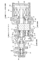
図1は、本発明にかかる単機スクリュー式多段圧縮機の実施形態を示す側面断面図であり、図2は単機スクリュー式多段圧縮機の実施形態を示す平面断面図である。
図3は図1のA−A線拡大断面図であり、図4は図2のB−B線拡大断面図である。
図5は本発明の実施形態にかかわる単機スクリュー式多段圧縮機を用いた冷凍・冷却システムの概略構成図であり、図6は図5の冷凍・冷却システムのモリエル線図である。
図7は本発明の実施形態にかかわる単機スクリュー式多段圧縮機を用いた冷凍・冷却システムの他の実施形態を示す概略構成図であり、図8は図7の冷凍・冷却システムのモリエル線図である。図9は、低段圧縮機と高段圧縮機との風量比と、成績係数(COP)との関係を示す特性図である。
FIG. 1 is a side sectional view showing an embodiment of a single-machine screw type multistage compressor according to the present invention, and FIG. 2 is a plan sectional view showing an embodiment of a single-machine screw type multistage compressor.
3 is an enlarged sectional view taken along line AA in FIG. 1, and FIG. 4 is an enlarged sectional view taken along line BB in FIG.
FIG. 5 is a schematic configuration diagram of a refrigeration / cooling system using a single-screw multistage compressor according to an embodiment of the present invention, and FIG. 6 is a Mollier diagram of the refrigeration / cooling system of FIG.
FIG. 7 is a schematic configuration diagram showing another embodiment of a refrigeration / cooling system using a single-screw multistage compressor according to an embodiment of the present invention, and FIG. 8 is a Mollier diagram of the refrigeration / cooling system of FIG. It is. FIG. 9 is a characteristic diagram showing the relationship between the air flow ratio between the low-stage compressor and the high-stage compressor and the coefficient of performance (COP).
図1に示すように、単機スクリュー式多段圧縮機として低段圧縮機1と高段圧縮機3とからなる単機スクリュー式2段圧縮機5について説明する。
低段圧縮機1は雄・雌一対のスクリューロータ7、9が噛合って回転可能に、低段圧縮機ケーシング11内に収容され、高段圧縮機3は雄・雌一対のスクリューロータ13、15が噛合って回転可能に高段圧縮機ケーシング17内に収容されている。また、図1、2に示すように、低段圧縮機1の雄・雌一対のスクリューロータ7、9は左右に並んで配設され、高段圧縮機3の雄・雌一対のスクリューロータ13、15は上下に並んで配設されるように、低段側を水平配置し高段側を縦配置してそれぞれ直交する方向に並んで配設されている。
As shown in FIG. 1, a single-screw two-
The low-
低段圧縮機1の低段雄ロータ7のロータ軸19と高段圧縮機3の高段雄ロータ13のロータ軸21とは、スプラインカップリング23を介して一体回転可能に結合される。すなわち、低段圧縮機1と高段圧縮機3とは分割軸構造からなり、スプラインカップリング23によって一体結合されるため、低段圧縮機1および高段圧縮機3を連続した一体軸によって連結する構造に比べて、軸の加工精度が要求されないため、加工製造が容易で低コストで製造できる。
The
また、低段雄ロータ7のロータ軸19は、モータ(駆動モータ)25の回転軸27を兼ねていて一体軸構造となっている。このモータ25は、モータケーシング29が低段圧縮機ケーシング11に気密状態で取付けられことによって密封式のモータ25に構成されるとともに、モータ25は、モータロータ内部に永久磁石が埋め込まれるいわゆるIPMモータによって構成されている。
モータ25の回転軸27とロータ軸19とロータ軸21とは一体回転するようになっている。
The
The rotating
モータ25の回転軸27は軸受31によって低段圧縮機ケーシング11に支持され、低段雄ロータ7の吐出側のロータ軸19は、中間ケーシング33に軸受35によって支持され、低段雌ロータ9のロータ軸37は、軸受39によって低段圧縮機ケーシング11に、軸受41によって中間ケーシング33にそれぞれ支持されている。
また、高段雄ロータ13のロータ軸21は、軸受43によって高段圧縮機ケーシング17に支持され、軸受45によって吐出口ケーシング47に支持されている。また、高段雌ロータ15のロータ軸22も同様に、軸受49によって高段圧縮機ケーシング17に支持され、軸受51によって吐出口ケーシング47に支持されている。
The
The
高段雄ロータ13のロータ軸21の端部には、該端部を覆う端部ケーシング53が取付けられ、さらに蓋55が取付けられる。
An
また、低段圧縮機ケーシング11には作動流体(冷媒)の吸込口57が設けられ、低段雄ロータ7および低段雌ロータ9のそれぞれのモータ25側の端面に対向して開口して設けられている。
低段圧縮機1の吐出口59は、吸込口57とは反対側の前記低段雄、雌ロータ7、9の端面に設けられ、吐出通路61を介して中間圧力室63に連通している。
中間圧力室63には、高段圧縮機3の吸込口65が開口し、前記高段雄、雌ロータ13、15の端面から冷媒が流入されるようになっている。
さらに、高段圧縮機3の吐出口67(図2)が、吐出口ケーシング47に形成され、高段圧縮機3で圧縮された冷媒が吐出されるようになっている。
The low-
The
A
Further, a discharge port 67 (FIG. 2) of the
前記した、モータケーシング29、低段圧縮機ケーシング11、中間ケーシング33、高段圧縮機ケーシング17、吐出口ケーシング47、端部ケーシング53、および蓋55はボルト等の締結手段によってそれぞれ結合されて一体に組み立てられて、単機構造を構成している。
The
(低段エコノマイザー、高段エコノマイザー)
次に、低段エコノマイザーポート70、高段エコノマイザーポート72について図1、2を参照して説明する。
低段エコノマイザーポート70は、低段エコノマイザー冷却器(後述の冷凍システムで説明)からの冷媒を低段圧縮機1の圧縮室内に供給するポートであり、中間ケーシング33に一箇所形成された低段エコノマイザーポート入口74から、低段雄ロータ7の雄側エコノマイザーポート76と、低段雌ロータ9の雌側エコノマイザーポート78へとそれぞれ連通している。
(Low stage economizer, High stage economizer)
Next, the low stage economizer port 70 and the high stage economizer port 72 will be described with reference to FIGS.
The low-stage economizer port 70 is a port for supplying refrigerant from the low-stage economizer cooler (described in a refrigeration system described later) into the compression chamber of the low-
この雄側エコノマイザーポート76、雌側エコノマイザーポート78はそれぞれ、中間ケーシング33に形成され、低段雄・雌ロータ7、9の軸方向であって吸込口57と反対側の雄・雌ロータ7、9端面に対向する位置に開口している。
そして、前記雄側および雌側エコノマイザーポート76、78はそれぞれ雄・雌ロータ7、9に形成されているスクリュー羽根の間に位置される大きさに形成されている(図3参照)。
The
The male-side and female-
このように、低段エコノマイザーポート70が雄・雌ロータ7、9の軸方向端面に対向して形成されているため、ロータのスクリュー羽根の枚数が増えて羽根の厚さが薄くなっても、そのスクリュー羽根の間に冷媒を流入するポートの加工が容易であり、またポート数の増減に対しては対応しやすく、エコノマイザーの冷媒流入量の増大への対応が容易である。
Thus, since the low stage economizer port 70 is formed facing the axial end surfaces of the male and
また、雄側エコノマイザーポート76と雌側エコノマイザーポート78との両方から低段圧縮機1に冷媒が流入するようになるため、低段エコノマイザーポート70の開口面積が大きくとれるため、エコノマイザー量を増大させることができる。
さらに、低段エコノマイザーポート70が雄・雌ロータ7、9の端面側の中間ケーシング33にまとめて形成されるため、エコノマイザーポートの加工、製造が容易になる。
Further, since the refrigerant flows into the low-
Furthermore, since the low-stage economizer port 70 is formed together in the intermediate casing 33 on the end face side of the male /
さらに、雄側および雌側エコノマイザーポート76、78は、それぞれ雄・雌ロータ7、9のスクリュー羽根の間に位置される大きさに形成されるため、雄ロータ7および雌ロータ9の圧縮行程に確実に冷媒を流入することができる。
Furthermore, since the male side and female
高段エコノマイザーポート72は、中間圧力室63が形成されている高段圧縮機ケーシング17に形成され、中間圧力室63から高段圧縮機3に冷媒が吸込まれるようになっている。
The high stage economizer port 72 is formed in the high
(バランス通路)
次に、バランス通路80について図1を参照して説明する。
このバランス通路80とは、中間圧力室63とモータケーシング29内のモータ室82とを連通する通路であり、中間圧力室63内の高圧の冷媒をモータ室82内に導くものである。また、中間圧力室63内の圧力でなくても、高段圧縮機3の圧縮行程部の圧力をモータ室82に導くようにしてもよい。
(Balance passage)
Next, the
The
低段圧縮機1に低段エコノマイザーを接続して風量比を従来よりも大きくすると、低段圧縮機1の吐出口59と高段圧縮機3の吸込口65とを連結する中間圧力室63内の圧力が従来よりも高くなって、低段圧縮機1をモータ25の方へ押し付けるスラスト荷重が作用するため、低段圧縮機1の軸受31、35、39、41の寿命が低下する問題が生じやすい。
When a low-stage economizer is connected to the low-
しかし、モータ25を密閉式によって構成し、中間圧力室63内の圧力、または高段圧縮機3の圧縮行程部の圧力を密閉式のモータ室82に導くことで、低段圧縮機1のモータ25方向に作用するスラスト荷重を打ち消すように逆向きに作用させるので、低段圧縮機1のスラスト荷重をバランスさせることで、低段圧縮機1の軸受31、35、39、41に作用する荷重を軽減して長寿命化を達成することができる。
However, the
また、低段圧縮機1の軸受31には、冷媒溶解潤滑油が供給され、前記密閉式モータのモータ室82内に戻すように構成されている。なお、モータ室82および中間圧力室63の底部には冷媒溶解潤滑油が貯留されるようになっていて、連通路84によって、それぞれの貯留部が連通されている。そして、連通路84によってモータ室82内の油を中間圧力室63から高段圧縮機3へ容易に戻すことができるようになっている。
The bearing 31 of the low-
さらに、図1に示すように、低段圧縮機1の雄・雌ロータ7、9が水平配置され、高段圧縮機3の雄・雌ロータ13、15が縦配置の構成となっていることによって、水平配置された低段側のスクリューロータの下方のスペースを利用して前記バランス通路80および連通路84を設置することができるので、単機スクリュー式多段圧縮機を大型化せずにコンパクトにバランス通路80および連通路84を設置することができる。
Further, as shown in FIG. 1, the male and
冷媒が溶解した油を潤滑油として使用する場合に低段圧縮機1の軸受31に給油した後に、低段圧縮機1の雄・雌ロータ7、9内に戻すと溶解していた冷媒が噴出して性能を著しく低下する問題が生じやすいが、低段圧縮機1の軸受31に供給された冷媒溶解潤滑油を密閉式のモータ室82内に戻すことで、該モータ室82内が中間圧力室63の圧力、または高段圧縮機3の圧縮行程部の圧力を導いて高圧になっているため、冷媒溶解潤滑油が噴出して性能を著しく低下する問題を回避することができる。
When the oil in which the refrigerant is dissolved is used as the lubricating oil, when the oil is supplied to the bearing 31 of the
(雄・雌ロータのスクリュー羽根)
次に、低段雄ロータ7と低段雌ロータ9とのスクリュー羽根の断面形状、および噛合い状態を図3を参照し、高段雄ロータ13と高段雌ロータ15とについては図4を参照して説明する。
図3、図4に示すように、低段雄ロータ7は5枚羽根で、低段雌ロータ9は6枚羽根で構成され、また、高段雄ロータ13も5枚羽根で、高段雌ロータ15も6枚羽根で、高段雄ロータ13も5枚羽根で構成されている。
このように、低段圧縮機1および高段圧縮機3ともに、5枚と6枚の組合で同一枚数に設定している。従って、5枚と6枚との組み合わせによって噛合い長さが長く採れることで、シール性を向上し、高圧縮の圧縮機へ対応できる。
(Male and female rotor screw blades)
Next, refer to FIG. 3 for the cross-sectional shape and meshing state of the screw blades of the low-stage
As shown in FIGS. 3 and 4, the low-stage
Thus, both the low-
また、低段圧縮機1および高段圧縮機3ともに、5枚と6枚の組合であるため、低段圧縮機1と高段圧縮機3との吐出脈動の周波数が一致して、振動騒音の問題が生じやすいため、スプラインカップリング23による結合時に、低段圧縮機1と高段圧縮機3との両者の回転位相を適切にずらして組合わせるようにしている。
Further, since both the low-
また、図3に示すように、雄側エコノマイザーポート76が、低段雄ロータ7のスクリュー羽根の間に開口するように形成され、雌側エコノマイザーポート78が、低段雌ロータ9のスクリュー羽根の間に開口するように形成されている。
なお、図3、4の矢印方向は、それぞれのロータの回転方向を示す。
Further, as shown in FIG. 3, the
3 and 4 indicate the rotation directions of the respective rotors.
(風量比)
次に、低段圧縮機1と高段圧縮機3との風量比について説明する。
高段圧縮機3は、低段圧縮機1で圧縮された冷媒等の流体をさらに圧縮するため、低段圧縮機1より風量(押しのけ量)は小さくしてあり、低段圧縮機1での風量と高段圧縮機3での風量比は性能が最適に発揮されるようにバランスして設定されている。
(Air volume ratio)
Next, the air volume ratio between the
Since the
低段圧縮機1にエコノマイザーが接続されていない従来の単機2段スクリュー圧縮機の場合には、一般的な運転条件(蒸発温度−50〜−20℃、凝縮温度30〜45℃)でのCOPの面から、低段圧縮機と高段圧縮機との理論風量比(低段圧縮機の高段圧縮機に対する理論風量比)は3.0以下として設定されていた。すなわち、図9の風量比とCOPとの関係に示すように、従来型の低段圧縮機のエコノマイザーがない場合には風量比が2.6〜2.7で最大となるため、3.0以下で使用していた。
In the case of the conventional single-stage two-stage screw compressor in which the economizer is not connected to the low-
ところが、低段圧縮機1にエコノマイザーを接続する場合には、風量比を高めて、図9に示すような3.2以上の風量比とすることが好ましく、従来の単機2段スクリュー圧縮機の場合における最大COPを上回るCOPを発揮するためには、3.2〜4.5の範囲に設定することが最適である。
However, when an economizer is connected to the low-
このように、低段圧縮機1にエコノマイザーを接続すると共に低段圧縮機の風量比を増大して最適化することでCOPを向上することができる。
さらに、低段圧縮機1の風量比の増大は、低段圧縮機1を大型化するか、または高段圧縮機3を小型化することによって達成することができるので、高段圧縮機3の小型化が可能になり、スクリュー式2段圧縮機5の安全性が高まり設置場所に制限を受けずに設置が可能になる。
Thus, COP can be improved by connecting the economizer to the
Further, the increase in the air flow ratio of the
(冷凍・冷却システム)
次に、冷凍・冷却システムについて図5〜8を参照して説明する。
図5は、単機スクリュー式2段圧縮機5を冷凍・冷却システムに適用した場合の構成図であり、冷媒はアンモニアを用いた例である。
冷凍システム100は、前記の単機構造のスクリュー式2段圧縮機5と、凝縮器102と、蒸発器104と、膨張手段106と、によって形成される主冷媒回路108に、前記凝縮器102の下流側でかつ前記蒸発器104の上流側で前記主冷媒回路108に高段エコノマイザー回路110と、低段エコノマイザー回路112とを備えて構成されている。
(Refrigeration / cooling system)
Next, the refrigeration / cooling system will be described with reference to FIGS.
FIG. 5 is a configuration diagram in the case where the single screw type two-
The refrigeration system 100 includes a single refrigerant screw type two-
高段エコノマイザー回路110の高段エコノマイザー通路114を高段圧縮機3の高段エコノマイザーポート72に接続し、低段エコノマイザー回路112の低段エコノマイザー通路116を低段圧縮機の低段エコノマイザーポート70に接続している。
The high
高段エコノマイザー回路110は、主冷媒回路108から分流した冷媒が、高段エコノマイザー膨張弁118に導かれて減圧され、低圧低温の冷媒となり高段エコノマイザー冷却器120に流入して主冷媒回路108の冷媒を冷却して、高段エコノマイザー通路114を通って高段圧縮機3の高段エコノマイザーポート72へ流入するように構成されている。
In the high-
また、低段エコノマイザー回路112も同様に、高段エコノマイザー冷却器120から吐出された冷媒の一部が分流して低段エコノマイザー膨張弁122に導かれて減圧され、低圧低温の冷媒となり低段エコノマイザー冷却器124に流入して、高段エコノマイザー冷却器120から吐出した冷媒を冷却して、低段エコノマイザー通路116を通って低段圧縮機1の低段エコノマイザーポート70に流入するように構成されている。
Similarly, in the low-
図6は、図5の冷凍サイクルのモリエル線図であり、図5および図6を参照して冷媒の流れを説明する。
スクリュー式2段圧縮機5によって圧縮されて高圧、高温(Td2)となった冷媒は、凝縮器102に流入してその熱を外部に放出して凝縮(凝縮温度Tc)して液化、低温化(TL)し、その後冷媒は分流し分流した冷媒は、高段エコノマイザー膨張弁118で減圧低温化(Tm2)されて高段エコノマイザー冷却器120を経て、高段エコノマイザーポート72に流入する。また、分流せずに残った冷媒は、高段エコノマイザー冷却器120で冷却されて低温化(TL1)される。
FIG. 6 is a Mollier diagram of the refrigeration cycle of FIG. 5, and the flow of the refrigerant will be described with reference to FIGS. 5 and 6.
The refrigerant that has been compressed by the screw-type two-
さらに、高段エコノマイザー冷却器120で冷却、低温化(TL1)された冷媒は、さらにその一部が分流されて、分流した冷媒は、低段エコノマイザー膨張弁122で減圧低温化(Tm1)されて低段エコノマイザー冷却器124を経て、低段エコノマイザーポート70に流入する。また、分流せずに残った冷媒は、低段エコノマイザー冷却器124で冷却されて低温化(TL2)される。
Further, a part of the refrigerant cooled and lowered in temperature (TL1) by the high-stage economizer cooler 120 is further divided, and the divided refrigerant is reduced in temperature and reduced in pressure by the low-stage economizer expansion valve 122 (Tm1). Then, the air flows into the low-stage economizer port 70 through the low-
低段エコノマイザー冷却器124からの冷媒は、主冷媒回路108の膨張手段106によって減圧低温化(Te)されて蒸発器104に流入する。蒸発器104では、外部から熱を奪い蒸発(蒸発温度Te)してガス冷媒と液冷媒とに分離されて、ガス冷媒(Ts1)が低段圧縮機1の吸込口57から吸い込まれ、吸込まれたガス冷媒は再び低段圧縮機1、および高段圧縮機3によって圧縮される。
The refrigerant from the low-stage economizer cooler 124 is decompressed and cooled (Te) by the expansion means 106 of the main
なお、低段圧縮機1の吐出温度をTd1、高段圧縮機3の吸込温度をTs2、高段エコノマイザーポート72の流入温度をTm2sで示し、低段エコノマイザーポート70の流入温度をTm1sで示し、その低段エコノマイザーが流入する低段圧縮機1の圧縮行程部の温度をTi1で示す。
Note that the discharge temperature of the
以上のように、冷媒が、主冷媒回路108の膨張手段106に送られる前に、高段エコノマイザー冷却器120、低段エコノマイザー冷却器124によって確実に冷却されるため、蒸発器104入口での比エンタルピーhを低下させることができ、冷凍・冷却システム100の冷却能力を向上することができる。
また、低段、高段それぞれのエコノマイザー回路110、112に注入する冷媒分だけ、低段圧縮機1、高段圧縮機3の圧縮仕事が減り、成績係数COPを向上することができる。
As described above, the refrigerant is reliably cooled by the high stage economizer cooler 120 and the low stage economizer cooler 124 before being sent to the expansion means 106 of the main
Further, the compression work of the low-
従来、単機構造のスクリュー式2段圧縮機においては、低圧段側には、エコノマイザー効果が得られにくく設置されていなかったが、本発明のように低段圧縮機1側でエコノマイザー効果が発揮されるような改良を加えることで、図6中に太実線で示されるTL1からTm1のラインで示されるような、低段圧縮機1側でのエコノマイザー効果が発揮されて、前記したような冷凍能力の向上によって冷凍・冷却システム100のCOPを向上することができる。
Conventionally, in the screw type two-stage compressor having a single machine structure, the economizer effect is not provided on the low pressure stage side so that the economizer effect is difficult to obtain, but the economizer effect is provided on the
次に、冷凍・冷却システムの他の実施形態について図7、8を参照して説明する。
図5、図6に示した実施形態に対して、低段エコノマイザー冷却器124と高段エコのマイザー冷却器120の構造が異なるだけで他の構成は同一のため、同一符号を付して説明は省略する。
Next, another embodiment of the refrigeration / cooling system will be described with reference to FIGS.
5 and 6 are the same except that the low-stage economizer cooler 124 and the high-stage economizer cooler 120 are different in structure. Description is omitted.
図7に示すように、冷凍・冷却システム200は、低段エコノマイザー回路130の低段エコノマイザー冷却器132および高段エコノマイザー回路134の高段エコノマイザー冷却器136がそれぞれフラッシュ型冷却器によって構成されている。
As shown in FIG. 7, in the refrigeration / cooling system 200, the low-stage economizer cooler 132 of the low-
凝縮器102を出た主冷媒回路108を流れる冷媒が、分流せずに全量が高段エコノマイザー膨張弁118に送られて、減圧低温化された後に高段エコノマイザー冷却器136でガス冷媒と液冷媒に分離される。そして、ガス冷媒だけが高段エコノマイザー通路114を通って高段エコノマイザーポート72へ流入されるようになっている。
The refrigerant flowing through the main
さらに、高段エコノマイザー冷却器136から液冷媒だけが、低段エコノマイザー膨張弁122に送られて、減圧低温化されて低段エコノマイザー冷却器132でガス冷媒と液冷媒に分離される。そして、ガス冷媒だけが低段エコノマイザー通路116を通って低段エコノマイザーポート70へ流入されるようになっている。
Further, only the liquid refrigerant is sent from the high stage economizer cooler 136 to the low stage
また、図7の冷凍サイクルのモリエル線図は図8に示すようになり、前記図5、6の実施形態と同様に、冷媒が、主冷媒回路108の膨張手段106に送られる前に、高段エコノマイザー冷却器136、低段エコノマイザー冷却器132によって確実に冷却されるため、蒸発器104入口での比エンタルピーhを低下させることができ、冷凍・冷却システム200の冷却能力を向上することができる。
また、低段、高段それぞれのエコノマイザー回路に注入する冷媒分だけ、低段圧縮機1、高段圧縮機3の圧縮仕事が減り、冷凍・冷却システム200のCOPを向上することができる。
Also, the Mollier diagram of the refrigeration cycle of FIG. 7 is as shown in FIG. 8, and, similar to the embodiment of FIGS. 5 and 6, before the refrigerant is sent to the expansion means 106 of the main
Further, the compression work of the low-
以上のように、単機スクリュー式2段圧縮機5を備えて冷凍サイクルを構成しているので、低段圧縮機1の風量比が大きく設定されるとともに、低段圧縮機1にエコノマイザー冷却器124、132が接続されるため、冷凍・冷却システムのCOPが向上する。
さらに、高段圧縮機3を小型、小容量化したシステムを構築することが可能になり、安全性が高まり設置場所の自由度が増える。
As described above, since the refrigeration cycle is configured by including the single-screw type two-
Furthermore, it becomes possible to construct a system in which the high-
さらに、低段圧縮機1の軸受31、35、39、41の長寿命化、さらに低段圧縮機1のエコノマイザーポート70の開口面積の拡大によるエコノマイザー効果の拡大によって、冷凍・冷却システムの長寿命化と高効率との両立を達成することができる。
Furthermore, by extending the life of the
本発明によれば、低段圧縮機と高段圧縮機とにそれぞれエコノマイザーを接続するとともに、低段圧縮機と高段圧縮機との風量比すなわち低段圧縮機の理論押しのけ量を従来の低段圧縮機にエコノマイザーを接続しない場合に比べて大きく設定して、低段圧縮機を高圧縮比としてエコノマイザー効果を低段圧縮機において効果的に発揮させることができる単機構造のスクリュー式多段圧縮機を提供することができる。
また、低段圧縮機を高圧縮化してエコノマイザー効果を発揮させるために、低段圧縮機へエコノマイザー冷却器からの冷媒がより流入しやすいエコノマイザーポート構造、および低段圧縮機からの吐出圧力が高くなることに伴う低段圧縮機に作用するスラスト荷重へ対応するための支持構造等を備えた単機スクリュー式多段圧縮機を提供することができる。
さらに、本発明によれば、その単機スクリュー多段圧縮機を用いて冷凍・冷却回路を構成することで、高いCOPを発揮する冷凍・冷却システムを提供することができる。
このため、単機スクリュー多段圧縮機を用いて構成する冷凍・冷却回路への適用に際して有益である。
According to the present invention, an economizer is connected to each of the low-stage compressor and the high-stage compressor, and the air volume ratio between the low-stage compressor and the high-stage compressor, that is, the theoretical displacement of the low-stage compressor is determined by the conventional method. A single-unit screw type that can be set larger than when an economizer is not connected to the low-stage compressor, and the economizer effect can be effectively demonstrated in the low-stage compressor by setting the low-stage compressor to a high compression ratio. A multi-stage compressor can be provided.
In addition, an economizer port structure that allows refrigerant from the economizer cooler to more easily flow into the low-stage compressor and discharge from the low-stage compressor in order to increase the compression of the low-stage compressor and exert the economizer effect. It is possible to provide a single-screw multi-stage compressor provided with a support structure for dealing with a thrust load acting on a low-stage compressor accompanying an increase in pressure.
Furthermore, according to the present invention, a refrigeration / cooling system that exhibits high COP can be provided by configuring a refrigeration / cooling circuit using the single-screw multistage compressor.
For this reason, it is useful when applied to a refrigeration / cooling circuit configured using a single-screw multistage compressor.
1 低段圧縮機
3 高段圧縮機
5 単機スクリュー式2段(多段)圧縮機
7 低段雄ロータ
9 低段雌ロータ
13 高段雄ロータ
15 高段雌ロータ
25 モータ
57、65 吸込口
59、67 吐出口
63 中間圧力室
70 低段エコノマイザーポート
72 高段エコノマイザーポート
76 雄側エコノマイザーポート
78 雌側エコノマイザーポート
80 バランス通路
102 凝縮器
104 蒸発器
106 膨張手段
108 主冷媒回路
124、132 低段エコノマイザー冷却器
120、136 高段エコノマイザー冷却器
110、134 高段エコノマイザー回路
112、130 低段エコノマイザー回路
DESCRIPTION OF
Claims (4)
前記低段圧縮機には低段エコノマイザー冷却器が接続される低段エコノマイザーポートが設けられ、前記モータを密閉式モータによって構成し、該モータを前記低段圧縮機の吸入側に連結し、前記低段圧縮機の吐出口と前記高段圧縮機の吸入口とを連結する中間圧力室の圧力、または前記高段圧縮機の圧縮行程部の圧力を前記モータ室に導くバランス通路が設けられていることを特徴とする単機スクリュー式多段圧縮機。 In a single-screw multi-stage compressor in which a low-stage compressor and a high-stage compressor comprising a pair of male and female screw rotors and a drive motor are combined in series,
The low-stage compressor is provided with a low-stage economizer port to which a low-stage economizer cooler is connected, the motor is constituted by a hermetic motor, and the motor is connected to the suction side of the low-stage compressor. A balance passage for guiding the pressure of the intermediate pressure chamber connecting the discharge port of the low-stage compressor and the suction port of the high-stage compressor or the pressure of the compression stroke portion of the high-stage compressor to the motor chamber. A single-screw multi-stage compressor characterized by the above.
Priority Applications (1)
| Application Number | Priority Date | Filing Date | Title |
|---|---|---|---|
| JP2012007415A JP5322016B2 (en) | 2012-01-17 | 2012-01-17 | Single screw multistage compressor and refrigeration / cooling system using the same |
Applications Claiming Priority (1)
| Application Number | Priority Date | Filing Date | Title |
|---|---|---|---|
| JP2012007415A JP5322016B2 (en) | 2012-01-17 | 2012-01-17 | Single screw multistage compressor and refrigeration / cooling system using the same |
Related Parent Applications (1)
| Application Number | Title | Priority Date | Filing Date |
|---|---|---|---|
| JP2007145957A Division JP5014880B2 (en) | 2007-05-31 | 2007-05-31 | Single screw multistage compressor and refrigeration / cooling system using the same |
Publications (2)
| Publication Number | Publication Date |
|---|---|
| JP2012102742A JP2012102742A (en) | 2012-05-31 |
| JP5322016B2 true JP5322016B2 (en) | 2013-10-23 |
Family
ID=46393384
Family Applications (1)
| Application Number | Title | Priority Date | Filing Date |
|---|---|---|---|
| JP2012007415A Active JP5322016B2 (en) | 2012-01-17 | 2012-01-17 | Single screw multistage compressor and refrigeration / cooling system using the same |
Country Status (1)
| Country | Link |
|---|---|
| JP (1) | JP5322016B2 (en) |
Family Cites Families (2)
| Publication number | Priority date | Publication date | Assignee | Title |
|---|---|---|---|---|
| JP2001182680A (en) * | 1999-12-27 | 2001-07-06 | Mitsubishi Electric Corp | Screw compressor |
| JP2006258397A (en) * | 2005-03-18 | 2006-09-28 | Mitsubishi Electric Corp | Refrigerator |
-
2012
- 2012-01-17 JP JP2012007415A patent/JP5322016B2/en active Active
Also Published As
| Publication number | Publication date |
|---|---|
| JP2012102742A (en) | 2012-05-31 |
Similar Documents
| Publication | Publication Date | Title |
|---|---|---|
| JP5014880B2 (en) | Single screw multistage compressor and refrigeration / cooling system using the same | |
| US7914267B2 (en) | Multistage compressor for a CO2 cycle that includes a rotary compressing mechanism and a scroll compressing mechanism | |
| CN101688536B (en) | Rotary compressor and refrigeration cycle device | |
| US10378539B2 (en) | System including high-side and low-side compressors | |
| US20110232325A1 (en) | Refrigerating apparatus | |
| KR101280155B1 (en) | Heat pump device, two-stage compressor, and method of operating heat pump device | |
| JP2004100608A (en) | Compressor | |
| JP2006258397A (en) | Refrigerator | |
| JP2001091071A (en) | Multi-stage compression refrigerating machine | |
| JP5338314B2 (en) | Compressor and refrigeration equipment | |
| JP6259309B2 (en) | Screw fluid machine and refrigeration cycle apparatus | |
| WO2020067196A1 (en) | Multistage compression system | |
| US20220325715A1 (en) | Scroll compressor with economizer injection | |
| US20110016913A1 (en) | Turbo compressor and refrigerator | |
| JP5322016B2 (en) | Single screw multistage compressor and refrigeration / cooling system using the same | |
| KR101330332B1 (en) | Two-stage screw compression type refrigerating device | |
| JP3966547B2 (en) | Screw-type multistage compressor switchable between multistage compression and single-stage compression, and refrigeration / cooling system using the same | |
| JPH03267592A (en) | Hermetic rotary compressor | |
| JP6370593B2 (en) | Oil-cooled multistage screw compressor and oil draining method thereof | |
| US10619635B2 (en) | Scallop step for a scroll compressor | |
| CN218376878U (en) | Rotary compressor and refrigeration cycle device | |
| US11162495B2 (en) | Oil circulation in a scroll compressor | |
| EP3350448A1 (en) | Intermediate discharge port for a compressor | |
| KR20200122774A (en) | Air Conditioning System applying expander | |
| JP2001124423A (en) | Multi-stage compression refrigerating device |
Legal Events
| Date | Code | Title | Description |
|---|---|---|---|
| A977 | Report on retrieval |
Free format text: JAPANESE INTERMEDIATE CODE: A971007 Effective date: 20120924 |
|
| A131 | Notification of reasons for refusal |
Free format text: JAPANESE INTERMEDIATE CODE: A131 Effective date: 20130326 |
|
| A521 | Request for written amendment filed |
Free format text: JAPANESE INTERMEDIATE CODE: A523 Effective date: 20130527 |
|
| TRDD | Decision of grant or rejection written | ||
| A01 | Written decision to grant a patent or to grant a registration (utility model) |
Free format text: JAPANESE INTERMEDIATE CODE: A01 Effective date: 20130618 |
|
| A61 | First payment of annual fees (during grant procedure) |
Free format text: JAPANESE INTERMEDIATE CODE: A61 Effective date: 20130705 |
|
| R150 | Certificate of patent or registration of utility model |
Ref document number: 5322016 Country of ref document: JP Free format text: JAPANESE INTERMEDIATE CODE: R150 Free format text: JAPANESE INTERMEDIATE CODE: R150 |
|
| R250 | Receipt of annual fees |
Free format text: JAPANESE INTERMEDIATE CODE: R250 |
|
| R250 | Receipt of annual fees |
Free format text: JAPANESE INTERMEDIATE CODE: R250 |
|
| R250 | Receipt of annual fees |
Free format text: JAPANESE INTERMEDIATE CODE: R250 |
|
| R250 | Receipt of annual fees |
Free format text: JAPANESE INTERMEDIATE CODE: R250 |
|
| R250 | Receipt of annual fees |
Free format text: JAPANESE INTERMEDIATE CODE: R250 |
|
| R250 | Receipt of annual fees |
Free format text: JAPANESE INTERMEDIATE CODE: R250 |