JP5317552B2 - Rolling dies - Google Patents
Rolling dies Download PDFInfo
- Publication number
- JP5317552B2 JP5317552B2 JP2008167361A JP2008167361A JP5317552B2 JP 5317552 B2 JP5317552 B2 JP 5317552B2 JP 2008167361 A JP2008167361 A JP 2008167361A JP 2008167361 A JP2008167361 A JP 2008167361A JP 5317552 B2 JP5317552 B2 JP 5317552B2
- Authority
- JP
- Japan
- Prior art keywords
- rolling
- layer depth
- depth
- nitrided
- practical
- Prior art date
- Legal status (The legal status is an assumption and is not a legal conclusion. Google has not performed a legal analysis and makes no representation as to the accuracy of the status listed.)
- Active
Links
Images


Classifications
-
- C—CHEMISTRY; METALLURGY
- C23—COATING METALLIC MATERIAL; COATING MATERIAL WITH METALLIC MATERIAL; CHEMICAL SURFACE TREATMENT; DIFFUSION TREATMENT OF METALLIC MATERIAL; COATING BY VACUUM EVAPORATION, BY SPUTTERING, BY ION IMPLANTATION OR BY CHEMICAL VAPOUR DEPOSITION, IN GENERAL; INHIBITING CORROSION OF METALLIC MATERIAL OR INCRUSTATION IN GENERAL
- C23C—COATING METALLIC MATERIAL; COATING MATERIAL WITH METALLIC MATERIAL; SURFACE TREATMENT OF METALLIC MATERIAL BY DIFFUSION INTO THE SURFACE, BY CHEMICAL CONVERSION OR SUBSTITUTION; COATING BY VACUUM EVAPORATION, BY SPUTTERING, BY ION IMPLANTATION OR BY CHEMICAL VAPOUR DEPOSITION, IN GENERAL
- C23C8/00—Solid state diffusion of only non-metal elements into metallic material surfaces; Chemical surface treatment of metallic material by reaction of the surface with a reactive gas, leaving reaction products of surface material in the coating, e.g. conversion coatings, passivation of metals
- C23C8/06—Solid state diffusion of only non-metal elements into metallic material surfaces; Chemical surface treatment of metallic material by reaction of the surface with a reactive gas, leaving reaction products of surface material in the coating, e.g. conversion coatings, passivation of metals using gases
- C23C8/36—Solid state diffusion of only non-metal elements into metallic material surfaces; Chemical surface treatment of metallic material by reaction of the surface with a reactive gas, leaving reaction products of surface material in the coating, e.g. conversion coatings, passivation of metals using gases using ionised gases, e.g. ionitriding
-
- B—PERFORMING OPERATIONS; TRANSPORTING
- B21—MECHANICAL METAL-WORKING WITHOUT ESSENTIALLY REMOVING MATERIAL; PUNCHING METAL
- B21H—MAKING PARTICULAR METAL OBJECTS BY ROLLING, e.g. SCREWS, WHEELS, RINGS, BARRELS, BALLS
- B21H3/00—Making helical bodies or bodies having parts of helical shape
- B21H3/02—Making helical bodies or bodies having parts of helical shape external screw-threads ; Making dies for thread rolling
-
- C—CHEMISTRY; METALLURGY
- C23—COATING METALLIC MATERIAL; COATING MATERIAL WITH METALLIC MATERIAL; CHEMICAL SURFACE TREATMENT; DIFFUSION TREATMENT OF METALLIC MATERIAL; COATING BY VACUUM EVAPORATION, BY SPUTTERING, BY ION IMPLANTATION OR BY CHEMICAL VAPOUR DEPOSITION, IN GENERAL; INHIBITING CORROSION OF METALLIC MATERIAL OR INCRUSTATION IN GENERAL
- C23C—COATING METALLIC MATERIAL; COATING MATERIAL WITH METALLIC MATERIAL; SURFACE TREATMENT OF METALLIC MATERIAL BY DIFFUSION INTO THE SURFACE, BY CHEMICAL CONVERSION OR SUBSTITUTION; COATING BY VACUUM EVAPORATION, BY SPUTTERING, BY ION IMPLANTATION OR BY CHEMICAL VAPOUR DEPOSITION, IN GENERAL
- C23C8/00—Solid state diffusion of only non-metal elements into metallic material surfaces; Chemical surface treatment of metallic material by reaction of the surface with a reactive gas, leaving reaction products of surface material in the coating, e.g. conversion coatings, passivation of metals
- C23C8/80—After-treatment
Landscapes
- Chemical & Material Sciences (AREA)
- Engineering & Computer Science (AREA)
- Mechanical Engineering (AREA)
- Chemical Kinetics & Catalysis (AREA)
- Materials Engineering (AREA)
- Metallurgy (AREA)
- Organic Chemistry (AREA)
- Solid-Phase Diffusion Into Metallic Material Surfaces (AREA)
- Forging (AREA)
- Heat Treatment Of Articles (AREA)
Description
本発明は転造ダイスに係り、特に、転造成形面のチッピングや欠損を抑制しつつ表面硬さを高くして優れた耐摩耗性や耐久性が得られるようする技術に関するものである。 The present invention relates to a rolling die, and more particularly, to a technique for obtaining excellent wear resistance and durability by increasing surface hardness while suppressing chipping and chipping on a rolling molding surface.
被転造部材の表面に食い込んで転造加工を行う転造成形面の表層部に窒化拡散層が設けられている転造ダイスが、ねじや歯車、スプラインなどの転造加工に広く用いられている。このような転造ダイスは、一般にJISに規定のSKD(合金工具鋼)やSKH(高速度工具鋼)を工具基材として用いて、塩浴窒化処理やガス窒化処理により表層部に窒化拡散層が設けられている。また、特許文献1には、イオン窒化処理により窒化拡散層を設けることが提案されている。
しかしながら、このような従来の転造ダイスにおいては、窒化拡散層の表面に窒化物等の硬くて脆い化合物層が形成されるため、表面硬さは高くなるもののチッピングや欠損が発生し易くなり、期待通りの耐摩耗性および耐久性の向上効果が得られないという問題があった。また、特に塩浴窒化処理やガス窒化処理では、所定の表面硬さを得ようとすると、窒化拡散層が深くなって内部まで硬度が高くなり、靱性が低下して脆くなるため、この点でも欠損が発生し易くなる。 However, in such a conventional rolling die, since a hard and brittle compound layer such as a nitride is formed on the surface of the nitrided diffusion layer, the surface hardness is high, but chipping and defects are likely to occur. There was a problem that the effect of improving the wear resistance and durability as expected could not be obtained. In particular, in salt bath nitriding and gas nitriding, if a predetermined surface hardness is obtained, the nitrided diffusion layer becomes deeper and the hardness increases to the inside, and the toughness decreases and becomes brittle. Defects are likely to occur.
本発明は以上の事情を背景として為されたもので、その目的とするところは、窒化処理により転造ダイスの転造成形面を硬化させて耐摩耗性を向上させる場合に、化合物層や靱性の低下に起因するチッピング、欠損の発生を抑制して耐久性を一層向上させることにある。 The present invention has been made against the background of the above circumstances, and its object is to improve the wear resistance by hardening the rolling surface of the rolling die by nitriding treatment, and to improve the compound layer and toughness. It is to further improve the durability by suppressing the occurrence of chipping and defects due to the decrease in the thickness.
かかる目的を達成するために、第1発明は、被転造部材の表面に食い込んで転造加工を行う転造成形面の表層部に窒化拡散層が設けられている転造ダイスにおいて、(a) 前記窒化拡散層は、表面に形成される化合物層深さが1μm以下で、実用窒化層深さが5〜40μmの範囲内で、且つ、表面硬さが1300HV以上または表面硬化量が400HV以上となるように、イオン窒化処理によって形成されており、(b) その窒化拡散層の上には、他の改質処理を行うことなく酸化処理が施されて膜厚さが1〜5μmの酸化被膜が設けられていることを特徴とする。 To achieve the above object, the first invention is a rolling die which nitride diffusion layer is provided on a surface layer portion of the rolling molding surface for performing rolling bite into the surface of the rolling member, (a The nitride diffusion layer has a compound layer depth of 1 μm or less, a practical nitride layer depth of 5 to 40 μm, a surface hardness of 1300 HV or more, or a surface hardening amount of 400 HV or more. (B) Oxidation treatment is performed on the nitrided diffusion layer without any other modification treatment, and the film thickness is 1 to 5 μm. A coating is provided .
なお、化合物層深さおよび実用窒化層深さは、JISのG 0562(1993)の「鉄鋼の窒化層深さ測定方法」に規定されているもので、化合物層深さは、窒化物、炭化物、炭窒化物などを主体とする層の表面からの深さであり、実用窒化層深さは、窒化層の表面から、生地のビッカース硬さ値又はヌーブ硬さ値より50高い硬さの点に至るまでの距離である。
また、表面硬化量は、表面硬さと生地のビッカース硬さ値又はヌーブ硬さ値との差を意味している。
The compound layer depth and the practical nitride layer depth are those defined in “Method of measuring the nitride layer depth of steel” in JIS G 0562 (1993). The depth from the surface of the layer mainly composed of carbonitride, etc. The practical nitrided layer depth is a point of
Further, the surface hardening amount means a difference between the surface hardness and the Vickers hardness value or the Nove hardness value of the fabric.
第2発明は、第1発明の転造ダイスにおいて、工具基材の表面に、他の改質処理を行うことなく前記イオン窒化処理が施されて前記窒化拡散層が設けられていることを特徴とする。 According to a second aspect of the present invention, in the rolling die of the first aspect, the surface of the tool base is subjected to the ion nitriding treatment without performing another modification treatment, and the nitriding diffusion layer is provided. And
すなわち、イオン窒化処理によって窒化拡散層を形成する場合、例えば雰囲気ガス(窒素ガスと水素ガスとの混合割合や圧力など)や温度、処理時間等の処理条件によって化合物層深さや実用窒化層深さをコントロールすることが可能で、それ等の化合物層深さや実用窒化層深さを種々変更して抗折力および損耗量との関係を調べたところ、化合物層深さが1μm以下で且つ実用窒化層深さが5〜40μmの範囲内の場合に、高い抗折力が得られるとともに損耗量が少なくて優れた耐摩耗性が得られることを見い出したのである。これは、化合物層深さが1μm以下であると、硬くて脆い化合物層の影響をあまり受けなくなるとともに、実用窒化層深さが40μm以下で比較的浅いと靱性が良好に維持され、それ等の相乗効果で高い抗折力すなわち欠損強度が得られるようになるものと考えられる。また、転造加工において優れた耐摩耗性が得られる表面硬さ或いは表面硬化量を得るためには、実用窒化層深さを5μm以上とする必要があり、特に表面硬さが1300HV以上或いは表面硬化量が400HV以上となるように上記処理条件が定められることにより、転造ダイスの早期のチッピングや欠損の発生を抑制しつつ優れた耐摩耗性が得られるようになって、耐久性を大幅に向上させることができる。 That is, when a nitrided diffusion layer is formed by ion nitriding, for example, the compound layer depth or the practical nitrided layer depth depends on the processing conditions such as atmospheric gas (mixing ratio and pressure of nitrogen gas and hydrogen gas), temperature, processing time, etc. When the relationship between the bending strength and the amount of wear was investigated by variously changing the compound layer depth and the practical nitride layer depth, the compound layer depth was 1 μm or less and the practical nitride was used. It has been found that when the layer depth is in the range of 5 to 40 μm, a high bending strength can be obtained and an excellent wear resistance can be obtained with a small amount of wear. This is because when the compound layer depth is 1 μm or less, it is less affected by the hard and brittle compound layer, and when the practical nitride layer depth is 40 μm or less and relatively shallow, the toughness is maintained well. It is considered that a high bending strength, that is, a defect strength can be obtained by a synergistic effect. In addition, in order to obtain surface hardness or surface hardening amount that provides excellent wear resistance in the rolling process, it is necessary to set the practical nitride layer depth to 5 μm or more, particularly surface hardness of 1300 HV or more or surface By setting the above processing conditions so that the curing amount is 400 HV or more, excellent wear resistance can be obtained while suppressing the occurrence of early chipping and chipping of the rolling die, greatly increasing the durability. Can be improved.
また、窒化拡散層の上に酸化処理によって膜厚さが1〜5μmの酸化被膜が設けられているため、この酸化被膜によって潤滑油剤の保持性能が向上し、転造ダイスに必要な潤滑性能や耐焼付き性能が向上して一層優れた耐摩耗性、耐久性が得られるようになる。 In addition, since an oxide film having a thickness of 1 to 5 μm is provided on the nitrided diffusion layer by oxidation treatment, this oxide film improves the holding performance of the lubricating oil agent, and the lubrication performance necessary for the rolling die The seizure resistance is improved, and more excellent wear resistance and durability can be obtained.
本発明は、丸ダイスや平ダイス、プラネタリ式ダイスなど、種々の転造ダイスに適用される。また、ねじ転造ダイスが広く知られているが、歯車やスプライン等のねじ以外の種々の部品を転造加工する転造ダイスにも適用され得る。転造ダイスの材質(工具基材)は、合金工具鋼や高速度工具鋼などの工具鋼が好適に用いられる。 The present invention is applied to various rolling dies such as round dies, flat dies, and planetary dies. Moreover, although a thread rolling die is widely known, the present invention can also be applied to a rolling die for rolling various parts other than screws such as gears and splines. As the material of the rolling die (tool base material), tool steel such as alloy tool steel or high-speed tool steel is preferably used.
イオン窒化処理は、例えば窒素ガス(N2 )と水素ガス(H2 )との混合ガスを用いて行われるが、アンモニア(NH3 )を用いてイオン窒化処理を行うことも可能である。酸化被膜を形成するための酸化処理については、例えば水蒸気酸化処理が好適に用いられるが、他の酸化処理方法を採用することもできる。 The ion nitriding treatment is performed using, for example, a mixed gas of nitrogen gas (N 2 ) and hydrogen gas (H 2 ), but ion nitriding treatment can also be performed using ammonia (NH 3 ). As the oxidation treatment for forming the oxide film, for example, steam oxidation treatment is preferably used, but other oxidation treatment methods may be employed.
本発明の実施に際しては、ショットピーニング等の他の改質処理を行うことなく、工具基材の表面にイオン窒化処理を施して窒化拡散層を設けるとともに、その窒化拡散層の上に酸化処理によって酸化被膜を設けることが望ましい。 In carrying out the present invention, an ion nitriding treatment is performed on the surface of the tool base to provide a nitriding diffusion layer without performing other modification treatment such as shot peening, and an oxidation treatment is performed on the nitriding diffusion layer. It is desirable to provide an oxide film.
以下、本発明の実施例を、図面を参照しつつ詳細に説明する。
図1は、本発明の一実施例であるねじ転造用の転造丸ダイス10を示す図で、(a) は斜視図、(b) は外周部の断面模式図である。この転造丸ダイス10は1対1組で使用されるもので、工具基材12はJISに規定のSKD(合金工具鋼)にて構成されているとともに、外周部の転造成形面14にはねじ溝に対応する断面形状の多数の凸条が設けられており、その凸条が円柱形状の被転造部材(ねじ素材)の表面に食い込むことによってねじを転造加工する。
Hereinafter, embodiments of the present invention will be described in detail with reference to the drawings.
1A and 1B are diagrams showing a rolling round die 10 for thread rolling according to an embodiment of the present invention. FIG. 1A is a perspective view, and FIG. 1B is a schematic cross-sectional view of an outer peripheral portion. The
上記転造成形面14には、ショットピーニング等の他の改質処理を行うことなくイオン窒化処理が施され、転造成形面14の表層部に窒素が拡散した窒化拡散層16が設けられる。イオン窒化処理は、真空炉内でグロー放電を起こさせ、窒素と水素の混合ガスの雰囲気中において、工具基材12に窒素を拡散侵入させる処理で、本実施例では実用窒化層深さt1が5〜40μmの範囲内で、表面硬さが1300HV以上または表面硬化量が400HV以上となる窒化拡散層16が得られるように、ガス圧やガスの混合割合、窒化処理の処理時間等の処理条件が定められている。このように実用窒化層深さt1が40μm以下で比較的浅いため、内部の靱性が良好に維持されてチッピングや欠損が抑制されるとともに、実用窒化層深さt1が5μm以上で表面硬さが1300HV以上または表面硬化量が400HV以上とされることにより、優れた耐摩耗性が得られる。
The rolling
上記イオン窒化処理ではまた、窒素と工具基材12の鉄等が反応して表面に窒化物等の化合物層が形成されるが、本実施例では、その化合物層の深さ(化合物層深さ)が1μm以下になるように処理条件が設定されている。この化合物層は硬くて脆いため、チッピングや欠損の原因になるが、本実施例では化合物層深さが1μm以下とされるため、その化合物層に起因するチッピングや欠損が抑制される。化合物層深さは、イオン窒化処理の処理時間に依存し、その処理時間は基本的には実用窒化層深さt1に応じて設定されるが、例えばイオン窒化処理を行う際の窒素ガス(N2 )と水素ガス(H2 )との混合割合を変更することによって化合物層深さを調整することができる。
In the ion nitriding process, nitrogen and iron of the
図2の(a) 〜(c) は、化合物層深さが異なる断面の電子顕微鏡写真で、(a) は化合物層深さが0μm、(b) は化合物層深さが約1μm、(c) は化合物層深さが約5μmの場合で、白層と呼ばれる白い部分が化合物層であり、他の部分と区別してその深さを測定することができる。 (A) to (c) in FIG. 2 are electron micrographs of cross sections having different compound layer depths. (A) is a compound layer depth of 0 μm, (b) is a compound layer depth of about 1 μm, (c ) Is a case where the compound layer depth is about 5 μm, and a white portion called a white layer is a compound layer, and the depth can be measured separately from other portions.
また、上記イオン窒化処理が施されて窒化拡散層16が設けられた転造成形面14には、更に、ショットピーニング等の他の改質処理を行うことなく水蒸気酸化処理が施され、表面に酸化被膜18が設けられる。水蒸気酸化処理は、500℃前後の水蒸気雰囲気中で転造丸ダイス10を加熱し、転造成形面14の表面に酸化被膜18を形成する処理で、本実施例では膜厚さが1〜5μmの酸化被膜18が設けられるように加熱温度や処理時間等の処理条件が定められる。この酸化被膜18は、酸素が工具基材12の鉄と反応して形成される多孔質の四三酸化鉄で、その孔内に潤滑油剤が良好に保持されて優れた潤滑性能が得られる。
Further, the rolling
このような本実施例の転造丸ダイス10によれば、窒化拡散層16の表面に形成される化合物層の深さが1μm以下であるため、硬くて脆い化合物層の影響をあまり受けなくなるとともに、実用窒化層深さt1が40μm以下で比較的浅いため内部の靱性が良好に維持され、それ等の相乗効果で高い抗折力が得られるようになる。また、実用窒化層深さt1が5μm以上で表面硬さが1300HV以上または表面硬化量が400HV以上であるため、上記抗折力の向上と相まって、転造ダイス10の早期のチッピングや欠損の発生を抑制しつつ優れた耐摩耗性が得られるようになり、耐久性が大幅に向上する。
According to the rolled round die 10 of this embodiment, since the depth of the compound layer formed on the surface of the
また、本実施例では窒化拡散層16の上に水蒸気酸化処理によって膜厚さが1〜5μmの酸化被膜18が設けられているため、この酸化被膜18によって潤滑油剤の保持性能が向上し、潤滑性能や耐焼付き性能が向上して一層優れた耐摩耗性、耐久性が得られるようになる。
Further, in this embodiment, the
因みに、図3は、ねじ転造用のダイプレート(転造平ダイス)について、図4の(a) に示す手順に従って転造成形面14に表面処理(イオン窒化+水蒸気酸化処理)を行って得られた本発明品と、図4の(b) に示す手順に従って表面処理(塩浴窒化+塩浴酸化処理)を行った従来品とを用意し、(a) に示す試験条件でねじの転造加工を行って耐久性を調べた結果を説明する図である。被転造材SCr430、SCM440は、それぞれJISに規定のクロム鋼、クロムモリブデン鋼である。
Incidentally, FIG. 3 shows the surface treatment (ion nitriding + steam oxidation treatment) on the rolling
ここで、上記本発明品は、図4の(a) のステップS1のイオン窒化処理において、500℃で1時間処理を行うことにより実用窒化層深さt1≒30μm、表面硬さ(HV0.3)が約1357HV(表面硬化量で約425HV)の窒化拡散層16が形成される。図5の「○」印は、上記イオン窒化処理を行って形成された窒化拡散層16の表面からの深さ寸法と硬さとの関係を調べた結果で、図4の(b) のステップR1に示す塩浴窒化処理で窒化拡散層を形成した場合(「□」印)と比較して示す図であり、イオン窒化処理では実用窒化層深さt1が約30μmと浅くても表面硬さは約1357HVに達し、内部の靱性を維持しつつ表面を高硬度に硬化させることができる。これに対し、塩浴窒化処理では、表面硬さが1300HV以下でも実用窒化層深さt1は約77μmに達し、内部まで硬化が進んで靱性が低下し、転造加工時に欠損等が発生し易くなる。なお、この図5において、実用窒化層深さt1を求める基準硬さ(生地のビッカース硬さ値+50)がイオン窒化処理の場合より塩浴窒化処理の方が高いのは、工具基材12の個体差や測定のばらつきなどによる。
Here, the product according to the present invention has a practical nitrided layer depth t1≈30 μm and surface hardness (HV 0.3) by performing the treatment at 500 ° C. for 1 hour in the ion nitriding treatment of step S1 in FIG. ) Of about 1357 HV (surface hardening amount of about 425 HV) is formed. The mark “◯” in FIG. 5 is the result of examining the relationship between the depth dimension and the hardness from the surface of the
また、化合物層深さは、イオン窒化処理を行う際の窒素ガス(N2 )と水素ガス(H2 )との混合割合を変更することによって調整され、本実施例ではN2 :H2 ≒1:1とされて化合物層深さが約0.3μmとされている。また、図4の(a) のステップS2の水蒸気酸化処理では、490℃で60分間処理が行われることにより、前記膜厚さt2が約2μmの酸化被膜18が形成される。
The depth of the compound layer is adjusted by changing the mixing ratio of nitrogen gas (N 2 ) and hydrogen gas (H 2 ) during ion nitriding, and in this embodiment, N 2 : H 2 ≈ The compound layer depth is about 0.3 μm. Further, in the steam oxidation process of step S2 in FIG. 4A, the
なお、従来品は、図4の(b) に示されるように、塩浴窒化処理によって窒化拡散層16が形成されるとともに、塩浴酸化処理によって酸化被膜18が設けられている。
In the conventional product, as shown in FIG. 4B, the
そして、上記の本発明品および従来品を用いて、図3の(a) に示す試験条件に従って転造加工を行い、工具の摩耗によりおねじの寸法が大きくなって、通りねじリングゲージ(GR)の通り抜けが不可となるゲージアウトとなるか、または工具欠損までの加工穴数(耐久寿命に相当)を調べたところ、図3の(b) に示す結果が得られた。この図3の(b) の試験結果から明らかなように、本発明品によれば、被転造材SCr430(40HRC)に対しては従来品に比較して約2倍の耐久寿命が得られ、被転造材SCM440(26HRC)に対しては従来品に比較して約1.6倍の耐久寿命が得られるようになり、何れの場合も耐久性が大幅に向上することが分かる。 Then, using the above-described product of the present invention and the conventional product, rolling is performed according to the test conditions shown in FIG. 3 (a), and the thread size is increased due to wear of the tool. ) When the gauge-out that makes it impossible to pass through or the number of drilled holes (corresponding to the endurance life) until tool failure was examined, the result shown in FIG. 3 (b) was obtained. As is apparent from the test results in FIG. 3 (b), according to the product of the present invention, the durability of the rolled material SCr430 (40HRC) is approximately twice that of the conventional product. The rolling material SCM440 (26HRC) has a durability life approximately 1.6 times that of the conventional product, and it can be seen that the durability is greatly improved in any case.
また、図6の(a) は、イオン窒化処理を行う際の窒素ガス(N2 )と水素ガス(H2 )との混合割合を変更するなどして化合物層深さが異なる幾つかの試験片を用意し、各試験片についてJIS R1601に規定されている曲げ強さ試験方法に従って抗折力を測定して、その抗折力と化合物層深さとの関係を調べた結果を示す図で、化合物層深さが1μmまでは抗折力が約3GPaであるのに対し、1μmを超えると急に低下傾向を示すようになる。試験片は5×4×10(mm)の直方体形状のSKD(合金工具鋼)で、全体に窒化処理層が設けられており、窒化拡散層の表面硬さは1358〜1369HV、実用窒化層深さは約30μm、酸化被膜の膜厚さは約2μmである。 FIG. 6 (a) shows several tests with different compound layer depths by changing the mixing ratio of nitrogen gas (N 2 ) and hydrogen gas (H 2 ) during ion nitriding. The figure which shows the result which prepared the piece and measured the bending strength according to the bending strength test method prescribed | regulated to JISR1601 about each test piece, and investigated the relationship between the bending strength and a compound layer depth, When the compound layer depth is 1 μm, the bending strength is about 3 GPa, whereas when the compound layer depth exceeds 1 μm, it suddenly shows a decreasing tendency. The test piece is a 5 × 4 × 10 (mm) rectangular SKD (alloy tool steel), and a nitriding layer is provided on the entire surface. The surface hardness of the nitriding diffusion layer is 1358 to 1369 HV, the practical nitriding layer depth The thickness is about 30 μm, and the thickness of the oxide film is about 2 μm.
図6の(b) は、イオン窒化処理を行う際の処理時間を変更するなどして実用窒化層深さが異なる幾つかの試験片を用意し、各試験片についてそれぞれ上記と同様にして抗折力を測定して、その抗折力と実用窒化層深さとの関係を調べた結果を示す図で、実用窒化層深さが40μmまでは抗折力が約3GPaであるのに対し、40μmを超えると急に低下傾向を示すようになる。上記各試験片の窒化拡散層の表面硬さは1358〜1369HVで、化合物層深さは約0.3μm、酸化被膜の膜厚さは約2μmである。そして、これ等の図6の(a) 、(b) の結果から、化合物層深さが1μm以下で且つ実用窒化層深さが40μm以下の場合に、3GPa程度以上の高い抗折力が得られることが分かる。 FIG. 6 (b) shows the preparation of several test pieces with different practical nitride depths by changing the processing time when performing ion nitriding, and for each test piece the same as above. It is a figure which shows the result of having measured bending force, and having investigated the relationship between the bending strength and practical nitrided layer depth, and when the practically nitrided layer depth is 40 μm, the bending strength is about 3 GPa, whereas 40 μm If it exceeds, it will show a downward trend suddenly. The surface hardness of the nitrided diffusion layer of each test piece is 1358 to 1369 HV, the compound layer depth is about 0.3 μm, and the thickness of the oxide film is about 2 μm. 6A and 6B, when the compound layer depth is 1 μm or less and the practical nitride layer depth is 40 μm or less, a high bending strength of about 3 GPa or more is obtained. You can see that
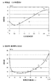
図7の(a) は、前記図3の耐久性試験で用いたものと同じねじ転造平ダイスについて、イオン窒化処理を行う際の窒素ガス(N2 )と水素ガス(H2 )との混合割合を変更するなどして化合物層深さが異なる幾つかの試験品を用意し、各試験品を用いて被転造材SCM440(26HRC)に対して図3(a) と同じ試験条件で10000個転造加工を行った後の転造成形面14の凸条の山頂の損耗量(高さの減少量)を測定して、その損耗量と化合物層深さとの関係を調べた結果を示す図で、化合物層深さが1μm以下であれば損耗量は約8μm以下であるのに対し、化合物層深さが1μmを超えるとチッピングを起こし易くなって損耗量は増大傾向を示すようになる。上記各試験品の窒化拡散層16の表面硬さは1358〜1369HVで、実用窒化層深さt1は約30μm、酸化被膜18の膜厚さt2は約2μmである。
(A) in FIG. 7 shows the relationship between nitrogen gas (N 2 ) and hydrogen gas (H 2 ) when performing ion nitriding treatment on the same thread rolling flat die used in the durability test of FIG. Prepare several test products with different compound layer depths by changing the mixing ratio, etc., and use each test product for the rolled material SCM440 (26HRC) under the same test conditions as in FIG. The amount of wear (the amount of decrease in height) of the ridges of the ridges of the rolling formed
図7の(b) は、同じくねじ転造平ダイスについて、イオン窒化処理の処理時間を変更するなどして実用窒化層深さt1が異なる幾つかの試験品を用意し、各試験品についてそれぞれ上記と同様にして損耗量を測定して、その損耗量と実用窒化層深さt1との関係を調べた結果を示す図で、実用窒化層深さt1が5μm〜40μmの範囲内では損耗量が約12μm以下であるのに対し、その範囲を超えるとチッピングを起こし易くなって損耗量は急に増加傾向を示すようになる。すなわち、実用窒化層深さt1が5μmよりも浅いと十分な表面硬さが得られなくて耐摩耗性が低下する一方、実用窒化層深さt1が40μmよりも深くなると靱性が低下して脆くなり、欠損等が生じ易くなって耐摩耗性が低下する。上記各試験品(実用窒化層深さt1が0μmのものを除く)の窒化拡散層16の表面硬さは1358〜1369HVで、化合物層深さは約0.3μm、酸化被膜18の膜厚さt2は約2μmである。そして、これ等の図7の(a) 、(b) の結果から、損耗量は実用窒化層深さt1の影響が大きく、実用窒化層深さt1が5〜40μmの範囲内であれば損耗量が約12μm以下になって、優れた耐摩耗性が得られることが分かる。
FIG. 7 (b) also shows several test products having different practical nitrided layer depths t1 by changing the processing time of the ion nitriding process for the thread rolling flat dies. It is a figure which shows the result of having measured the amount of wear in the same manner as described above, and examining the relationship between the amount of wear and the practical nitrided layer depth t1, and shows the amount of wear when the practically nitrided layer depth t1 is in the range of 5 μm to 40 μm. Is about 12 μm or less, however, if the range is exceeded, chipping is likely to occur, and the amount of wear tends to increase rapidly. That is, if the practical nitrided layer depth t1 is shallower than 5 μm, sufficient surface hardness cannot be obtained and wear resistance is reduced. On the other hand, if the practical nitrided layer depth t1 is deeper than 40 μm, the toughness is lowered and brittle. As a result, chipping or the like is likely to occur and wear resistance is reduced. The surface hardness of the
上記図6および図7の結果から、化合物層深さが1μm以下で、且つ、実用窒化層深さt1が5〜40μmの範囲内となるように窒化拡散層16を設ければ、チッピングや欠損の発生が抑制されて優れた耐摩耗性が得られるようになる。
From the results of FIG. 6 and FIG. 7, if the
以上、本発明の実施例を図面に基づいて詳細に説明したが、これ等はあくまでも一実施形態であり、本発明は当業者の知識に基づいて種々の変更,改良を加えた態様で実施することができる。 As mentioned above, although the Example of this invention was described in detail based on drawing, these are one embodiment to the last, and this invention is implemented in the aspect which added the various change and improvement based on the knowledge of those skilled in the art. be able to.
10:転造丸ダイス(転造ダイス) 12:工具基材 14:転造成形面 16:窒化拡散層 18:酸化被膜 t1:実用窒化層深さ t2:酸化被膜の膜厚さ 10: Rolled round die (rolling die) 12: Tool substrate 14: Rolling molding surface 16: Nitrided diffusion layer 18: Oxide film t1: Practical nitride layer depth t2: Film thickness of oxide film
Claims (2)
前記窒化拡散層は、表面に形成される化合物層深さが1μm以下で、実用窒化層深さが5〜40μmの範囲内で、且つ、表面硬さが1300HV以上または表面硬化量が400HV以上となるように、イオン窒化処理によって形成されており、
該窒化拡散層の上には、他の改質処理を行うことなく酸化処理が施されて膜厚さが1〜5μmの酸化被膜が設けられている
ことを特徴とする転造ダイス。 In a rolling die in which a nitrided diffusion layer is provided on the surface layer portion of a rolling molding surface that cuts into the surface of the rolled member and performs the rolling process,
The nitride diffusion layer has a compound layer depth of 1 μm or less, a practical nitride layer depth of 5 to 40 μm, a surface hardness of 1300 HV or more, or a surface hardening amount of 400 HV or more. becomes as are formed by the ion nitriding treatment,
A rolling die characterized in that an oxide film having a thickness of 1 to 5 μm is provided on the nitrided diffusion layer without being subjected to any other modification treatment .
ことを特徴とする請求項1に記載の転造ダイス。 2. The rolling die according to claim 1, wherein the surface of the tool base is subjected to the ion nitriding treatment without performing another modification treatment and the nitriding diffusion layer is provided. 3.
Priority Applications (4)
| Application Number | Priority Date | Filing Date | Title |
|---|---|---|---|
| JP2008167361A JP5317552B2 (en) | 2008-06-26 | 2008-06-26 | Rolling dies |
| US12/457,533 US20090320551A1 (en) | 2008-06-26 | 2009-06-15 | Thread rolling die |
| TW098120416A TWI474911B (en) | 2008-06-26 | 2009-06-18 | Thread rolling die |
| KR1020090057029A KR20100002194A (en) | 2008-06-26 | 2009-06-25 | Thread rolling die |
Applications Claiming Priority (1)
| Application Number | Priority Date | Filing Date | Title |
|---|---|---|---|
| JP2008167361A JP5317552B2 (en) | 2008-06-26 | 2008-06-26 | Rolling dies |
Publications (2)
| Publication Number | Publication Date |
|---|---|
| JP2010005654A JP2010005654A (en) | 2010-01-14 |
| JP5317552B2 true JP5317552B2 (en) | 2013-10-16 |
Family
ID=41445848
Family Applications (1)
| Application Number | Title | Priority Date | Filing Date |
|---|---|---|---|
| JP2008167361A Active JP5317552B2 (en) | 2008-06-26 | 2008-06-26 | Rolling dies |
Country Status (4)
| Country | Link |
|---|---|
| US (1) | US20090320551A1 (en) |
| JP (1) | JP5317552B2 (en) |
| KR (1) | KR20100002194A (en) |
| TW (1) | TWI474911B (en) |
Families Citing this family (5)
| Publication number | Priority date | Publication date | Assignee | Title |
|---|---|---|---|---|
| JP5988846B2 (en) * | 2012-11-28 | 2016-09-07 | オーエスジー株式会社 | Rolling tool and manufacturing method thereof |
| JP6111138B2 (en) * | 2013-05-13 | 2017-04-05 | オーエスジー株式会社 | Flat die for worm rolling and manufacturing method thereof |
| JP2015100797A (en) * | 2013-11-21 | 2015-06-04 | オーエスジー株式会社 | Rolling die |
| EP4094872B1 (en) * | 2020-03-26 | 2025-06-18 | OSG Corporation | Rolling die and method for manufacturing same |
| CN113930715A (en) * | 2021-08-31 | 2022-01-14 | 北京卫星制造厂有限公司 | Ion nitriding method for small-module gear |
Family Cites Families (16)
| Publication number | Priority date | Publication date | Assignee | Title |
|---|---|---|---|---|
| JPS5027809B1 (en) * | 1968-12-05 | 1975-09-10 | ||
| JPS52138027A (en) * | 1976-04-08 | 1977-11-17 | Nissan Motor | Ferrous member superior in initial fitting and wear resisting property and production process therefor |
| JPH0639011B2 (en) * | 1987-07-23 | 1994-05-25 | オ−エスジ−株式会社 | Thread cutting dies |
| US5087181A (en) * | 1989-03-06 | 1992-02-11 | Hitachi, Ltd. | Sliding structure such as compressor or the like |
| JP2568038B2 (en) * | 1993-11-15 | 1996-12-25 | 株式会社東芝 | Method of manufacturing material for polishing surface plate |
| JPH07252583A (en) * | 1994-03-11 | 1995-10-03 | Hitachi Metals Ltd | Spheroidal graphite cast iron for crank shaft |
| US5507169A (en) * | 1994-11-14 | 1996-04-16 | Cullen; William W. | Throw away thread rolling die |
| DE60033772T2 (en) * | 1999-12-24 | 2007-10-31 | Hitachi Metals, Ltd. | Martensitic hardening steel with high fatigue strength and martensitic hardening steel strip |
| DE10015691C1 (en) * | 2000-03-16 | 2001-07-26 | Thyssenkrupp Stahl Ag | Production of a non-grain oriented hot-rolled magnetic steel sheet used in the production of engines comprises rolling a pre-material made of an iron alloy and deforming in the mixed austenite/ferrite region |
| JP4202000B2 (en) * | 2000-07-10 | 2008-12-24 | トヨタ自動車株式会社 | Mandrel for ring rolling |
| JP2003013199A (en) * | 2001-04-23 | 2003-01-15 | Japan Science & Technology Corp | Method of modifying steel surface |
| JP3884246B2 (en) * | 2001-08-08 | 2007-02-21 | 本田技研工業株式会社 | CVT belt hoop manufacturing method |
| US8900382B2 (en) * | 2002-06-13 | 2014-12-02 | Uddeholm Tooling Aktiebolag | Hot worked steel and tool made therewith |
| JP4371072B2 (en) * | 2005-03-29 | 2009-11-25 | 住友金属工業株式会社 | High carbon steel sheet |
| KR100812971B1 (en) * | 2006-02-23 | 2008-03-13 | 일진경금속 주식회사 | Method for nitriding steel in salt bath and steel manufactured by its method |
| JP2008138235A (en) * | 2006-11-30 | 2008-06-19 | Osg Corp | Method for reforming rolling die, and rolling die |
-
2008
- 2008-06-26 JP JP2008167361A patent/JP5317552B2/en active Active
-
2009
- 2009-06-15 US US12/457,533 patent/US20090320551A1/en not_active Abandoned
- 2009-06-18 TW TW098120416A patent/TWI474911B/en not_active IP Right Cessation
- 2009-06-25 KR KR1020090057029A patent/KR20100002194A/en not_active Ceased
Also Published As
| Publication number | Publication date |
|---|---|
| TWI474911B (en) | 2015-03-01 |
| KR20100002194A (en) | 2010-01-06 |
| JP2010005654A (en) | 2010-01-14 |
| TW201008745A (en) | 2010-03-01 |
| US20090320551A1 (en) | 2009-12-31 |
Similar Documents
| Publication | Publication Date | Title |
|---|---|---|
| EP2548986B1 (en) | Steel for nitrocarburization and production method of a nitrocarburized steel part | |
| JP5299140B2 (en) | MATERIAL OF SHOT PEENING PROJECTION MATERIAL AND METHOD FOR PRODUCING SHOT PEENING PROJECTION MATERIAL | |
| JP5317552B2 (en) | Rolling dies | |
| WO2014196431A1 (en) | Bearing component and rolling bearing | |
| JP2010222648A (en) | Carbon steel material manufacturing method and carbon steel material | |
| JP7306581B2 (en) | steel parts | |
| EP3797894A1 (en) | Method for manufacturing forged article | |
| JP7116860B2 (en) | Rolling die and its manufacturing method | |
| JP2008138235A (en) | Method for reforming rolling die, and rolling die | |
| WO2025062988A1 (en) | Steel product and method for modifying steel product | |
| JP4865438B2 (en) | Surface treatment method of aluminum extrusion die and aluminum extrusion die | |
| US20100154938A1 (en) | Layered fe-based alloy and process for production thereof | |
| US20090047528A1 (en) | Surface treatment method of aluminum extruding die, and aluminum extruding die | |
| KR101263936B1 (en) | Method for drawing heat treatment depth in the product by specimen | |
| WO2014196430A1 (en) | Bearing part and rolling bearing | |
| WO2011077945A1 (en) | Nitriding process for maraging steel | |
| JP3314233B2 (en) | Surface nitriding method of steel sheet molded product and steel sheet molded product | |
| JP6832537B2 (en) | Rolled dies with excellent durability and their manufacturing methods | |
| JPH11304795A (en) | Nitrogen penetration depth detection method for steel parts | |
| CN101233255A (en) | Surface treatment method of aluminum extrusion die and aluminum extrusion die | |
| JP6064919B2 (en) | Annealing sleeve roll | |
| JP4829025B2 (en) | Method for producing layered Fe-based alloy | |
| JP2025112615A (en) | Steel parts | |
| WO2007015514A1 (en) | LAYERED Fe-BASED ALLOY AND PROCESS FOR PRODUCTION THEREOF | |
| JP2004332029A (en) | Nitrided tool, mold and method of manufacturing the same |
Legal Events
| Date | Code | Title | Description |
|---|---|---|---|
| A621 | Written request for application examination |
Free format text: JAPANESE INTERMEDIATE CODE: A621 Effective date: 20110131 |
|
| A977 | Report on retrieval |
Free format text: JAPANESE INTERMEDIATE CODE: A971007 Effective date: 20121114 |
|
| A131 | Notification of reasons for refusal |
Free format text: JAPANESE INTERMEDIATE CODE: A131 Effective date: 20121120 |
|
| A521 | Request for written amendment filed |
Free format text: JAPANESE INTERMEDIATE CODE: A523 Effective date: 20121213 |
|
| TRDD | Decision of grant or rejection written | ||
| A01 | Written decision to grant a patent or to grant a registration (utility model) |
Free format text: JAPANESE INTERMEDIATE CODE: A01 Effective date: 20130702 |
|
| A61 | First payment of annual fees (during grant procedure) |
Free format text: JAPANESE INTERMEDIATE CODE: A61 Effective date: 20130709 |
|
| R150 | Certificate of patent or registration of utility model |
Ref document number: 5317552 Country of ref document: JP Free format text: JAPANESE INTERMEDIATE CODE: R150 Free format text: JAPANESE INTERMEDIATE CODE: R150 |
|
| R250 | Receipt of annual fees |
Free format text: JAPANESE INTERMEDIATE CODE: R250 |
|
| R250 | Receipt of annual fees |
Free format text: JAPANESE INTERMEDIATE CODE: R250 |
|
| R250 | Receipt of annual fees |
Free format text: JAPANESE INTERMEDIATE CODE: R250 |
|
| R250 | Receipt of annual fees |
Free format text: JAPANESE INTERMEDIATE CODE: R250 |
|
| R250 | Receipt of annual fees |
Free format text: JAPANESE INTERMEDIATE CODE: R250 |
|
| R250 | Receipt of annual fees |
Free format text: JAPANESE INTERMEDIATE CODE: R250 |