JP5317543B2 - Wireless communication system - Google Patents
Wireless communication system Download PDFInfo
- Publication number
- JP5317543B2 JP5317543B2 JP2008155517A JP2008155517A JP5317543B2 JP 5317543 B2 JP5317543 B2 JP 5317543B2 JP 2008155517 A JP2008155517 A JP 2008155517A JP 2008155517 A JP2008155517 A JP 2008155517A JP 5317543 B2 JP5317543 B2 JP 5317543B2
- Authority
- JP
- Japan
- Prior art keywords
- transmission power
- directional antenna
- unit
- transmission
- radio
- Prior art date
- Legal status (The legal status is an assumption and is not a legal conclusion. Google has not performed a legal analysis and makes no representation as to the accuracy of the status listed.)
- Active
Links
Images
Landscapes
- Radio Relay Systems (AREA)
Abstract
Description
本願の発明は、電波の送受信に指向性アンテナを用いたギガヘルツ帯以上のマイクロ波やミリ波による無線通信システムに係り、特に、移動中継に好適な無線通信システムに関する。 The present invention relates to a radio communication system using microwaves or millimeter waves of a gigahertz band or higher that uses a directional antenna for transmitting and receiving radio waves, and more particularly to a radio communication system suitable for mobile relay.
例えばスポーツ中継など、野外において発生する種々の通信需要に応え、通信回線を半固定的に展開するためには、例えばパラボラアンテナなどの指向性アンテナを用いて2地点間での無線通信回線を確保するようにした移動用の無線通信システムが、従来から使用されている。
このとき、指向性のアンテナが用いられるのは、無線通信回線となる電波の伝送経路を細く絞ることにより、伝送経路の存在が知られてしまう虞を少なくし、妨害波による影響を抑え、伝送距離の増加と周波数資源の有効利用が図れるようにするためである。
In order to respond to various communication demands that occur in the field, such as sports broadcasts, and to develop a semi-fixed communication line, secure a wireless communication line between two points using a directional antenna such as a parabolic antenna. A mobile wireless communication system configured to do so has been used in the past.
At this time, a directional antenna is used because the transmission path of the radio wave that becomes the wireless communication line is narrowed down to reduce the possibility that the existence of the transmission path will be known, to suppress the influence of the interference wave, and to transmit This is to increase the distance and to effectively use the frequency resources.
ここで、図3は、このような移動用の通信システムにおいて、従来から用いられている無線通信装置の一例で、この場合、指向性空中線部11と送信部12、受信部13、電界強度測定部14、空中線駆動部17、それにサーキュレータSにより通信装置10が構成されている(例えば特許文献1参照)。
そして、この通信装置10を、見通し距離にある電波の伝送経路の一方の地点と他方の地点に、指向性空中線部11の双方が対向するようにしてそれぞれ配置し、無線通信システムを構成している。
Here, FIG. 3 is an example of a wireless communication apparatus conventionally used in such a mobile communication system. In this case, the directional antenna unit 11, the transmission unit 12, the
Then, this
ところで、このような無線通信システムにおいては、各通信装置10の設置に際して、各々の指向性空中線部11の指向方向が電波の送信源に正しく向い、指向性アンテナの最大利得点が得られるようにする調整、いわゆるアラインメント調整が必要である。
この場合、まず、当初は、作業者の目視により与えられる方位角、或いは地図から与えられる方位角により、各々の指向性空中線部11の向きを知り、その方向に設定することにより、とりあえず指向方向が相互に合うようにしておく。
By the way, in such a wireless communication system, when each
In this case, first, by knowing the direction of each directional antenna part 11 from the azimuth angle given by the operator's visual observation or the azimuth angle given from the map, and setting it in that direction, the directional direction for the time being Make sure they fit each other.
その後、各通信装置10では、指向性空中線部11に相手側からの電波が入感され、受信部13で信号が受信されている状態で、指向性空中線部11の向きを動かし、電界強度測定部14により測定されている電界強度が最大になる方向を求め、求まった方向を指向方向として指向性空中線部11に設定する。
このとき、電界強度が最大になったということは、そのとき、指向性空中線部11の指向方向が相手側に向う方向に一致したことを意味し、従って、上記のようにして求まった方向を指向性空中線部11に設定してやれば、指向方向が正しく設定できるのである。
Thereafter, in each
At this time, the fact that the electric field intensity is maximized means that the directivity direction of the directional antenna part 11 coincides with the direction toward the other side, and therefore the direction obtained as described above is obtained. If the directional antenna unit 11 is set, the directional direction can be set correctly.
ところで、このような無線通信システムの場合、その運用に際して、他の無線通信システムに干渉しないことが要件であり、このためには送信電力の抑制が有効である。
そこで、受信電波の電界強度に応じて送信電力が制御されるようにした送信レベル動的制御形通信装置を用いた無線通信システムも、従来から知られている。
Therefore, a wireless communication system using a transmission level dynamic control type communication apparatus in which transmission power is controlled in accordance with the electric field strength of a received radio wave is also known.
上記従来技術は、送信レベル動的制御形通信装置の存在に配慮がされておらず、このような通信装置による無線通信システムには適用が困難であるという問題があった。
すなわち、送信レベル動的制御形通信装置を用いた通信システムの場合、受信電波の電界強度が最大になる方向を見い出そうとして指向性アンテナの向きを変えたとき、受信電波の電界強度に応じて送信電力が制御されてしまうため、電界強度の変化が抑えられてしまうので、指向方向の設定が困難になってしまうのである。
The above prior art does not consider the existence of a transmission level dynamic control type communication device, and there is a problem that it is difficult to apply to a wireless communication system using such a communication device.
That is, in the case of a communication system using a transmission level dynamic control type communication device, when the direction of the directional antenna is changed in order to find the direction in which the electric field intensity of the received radio wave is maximized, the electric field intensity of the received radio wave is changed. Since the transmission power is controlled accordingly, the change in the electric field strength is suppressed, and the setting of the directivity direction becomes difficult.
従って、この従来技術の場合、指向性アンテナのアラインメント調整に際しては、通信装置を特別な動作モードにし、相手側の送信電力を固定させた上で自局のアラインメント調整を行い、次いで自局の送信電力を固定してから相手側でアラインメント調整を行うようにする必要があった。
本発明の目的は、特別な動作モードを持つことなく簡単に指向性アンテナのアラインメント調整が得られるようにした無線通信システムを提供することにある。
Therefore, in the case of this conventional technology, when adjusting the alignment of the directional antenna, the communication apparatus is set to a special operation mode, the transmission power of the other party is fixed, and the alignment of the own station is performed, and then the transmission of the own station is performed. It was necessary to adjust the alignment after the power was fixed.
An object of the present invention is to provide a wireless communication system that can easily adjust alignment of a directional antenna without having a special operation mode.
上記の目的は、一方と他方の無線局での電波の送受信に指向性アンテナを用いた中継用の無線通信システムにおいて、前記他方の無線局には、受信電力を計測し、計測した受信電力値を当該他方の無線局から前記一方の無線局に送信する信号に重畳させて伝送する送信データ生成部を設け、前記一方の無線局には、前記他方の無線局から伝送された前記受信電力値に応じて送信電力制御信号を発生し、当該一方の無線局から送信される送信電力を前記送信電力制御信号に応じて制御する送信電力制御部と、当該一方の無線局の受信部から入力される電界強度レベルを前記送信電力制御部より出力される前記送信電力制御信号により補正し、アナログ強度レベル電圧を算出するモニター電圧演算部とを設け、前記一方の無線局において、前記アナログ強度レベル電圧の値から前記指向性アンテナのアラインメント調整が得られるようにして達成される。 In the wireless communication system for relay using a directional antenna for transmission / reception of radio waves in one and the other radio station, the other radio station measures the received power and measures the received power value. Is provided with a transmission data generation unit that is superimposed on a signal transmitted from the other radio station to the one radio station, and the one radio station has the received power value transmitted from the other radio station. The transmission power control signal is generated according to the transmission power control signal, and the transmission power control unit that controls the transmission power transmitted from the one radio station according to the transmission power control signal and the reception unit of the one radio station are input. that the field strength level is corrected by the transmission power control signal outputted from the transmission power control unit is provided with the monitor voltage calculation unit for calculating an analog intensity-level voltage, in the one radio station, the a The alignment adjustment of the directional antenna from the value of log intensity level voltage is achieved as is obtained.
本発明によれば、送信レベル動的制御形通信装置を用いた場合でも、特別なモードにすることなく指向性アンテナのアラインメント調整が可能になり、この結果、高所など作業が困難な場所においても、常に安全に、しかも効率的にアラインメント調整を行うことができる。 According to the present invention, even when a transmission level dynamic control type communication device is used, alignment adjustment of a directional antenna is possible without using a special mode. As a result, in places where work is difficult such as high places. However, alignment adjustment can always be performed safely and efficiently.
以下、本発明に係る無線通信システムについて、図示の実施の形態により詳細に説明する。
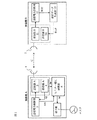
ここで、図1は、本発明の第1の実施形態で、これは、2台の無線機A、Bを用い、これらの無線機A、Bを一方と他方の無線通信装置とし、例えばパラボラアンテナなどの指向性アンテナ1、2を用い、これらの間をマイクロ波やミリ波の電波による伝送経路Cで結んで無線通信システムとしたものであり、このとき、無線機Aは、送信部3と受信部4、送信電力制御部5、モニター電圧演算部6、それに端子部7を備え、無線機Bは、送信部10と受信部11、受信電力計測部12、それに送信データ生成部13を備えている。
Hereinafter, a radio communication system according to the present invention will be described in detail with reference to embodiments shown in the drawings.
Here, FIG. 1 shows a first embodiment of the present invention, which uses two wireless devices A and B, and these wireless devices A and B are used as one and the other wireless communication device, for example, a parabola. A
始めに、このシステムによる中継動作について説明する。
この場合、無線機Aの送信部A3と無線機Bの受信部B11、無線機Bの送信部B10と無線機Aの受信部A4、それに無線機Aの指向性アンテナ1と無線機Bの指向性アンテナ2は夫々対になって無線機A側にある一方の外部機器(図示してない)と無線機B側にある他方の外部機器(図示してない)の間での無線通信による中継動作が得られるようになっている。
そして、まず、無線機Aには、無線機Bに伝送すべきデータ(例えばディジタル映像信号データ)が、一方の外部機器から入力され、これが送信部A3に供給される。
First, the relay operation by this system will be described.
In this case, the transmitter A3 of the radio A and the receiver B11 of the radio B, the transmitter B10 of the radio B and the receiver A4 of the radio A, and the directivity antenna 1 of the radio A and the directivity of the radio B The
First, data (for example, digital video signal data) to be transmitted to the wireless device B is input to the wireless device A from one external device, and this is supplied to the transmitting unit A3.
そこで、この入力されたデータより変調された高周波電力が送信部A3から指向性アンテナ1に供給され、この結果、無線機Bの指向性アンテナ2に電波が入感され、受信部B11により復調されたデータが他方の外部機器に供給される。
また、他方の外部機器から、無線機Aに伝送すべきデータ(例えば連絡用通話信号や制御データ)が無線機Bに入力された場合は、送信部B10から変調された高周波電力が指向性アンテナ2に供給され、この結果、無線機Aの指向性アンテナ1に電波が入感し、受信部A4により復調されたデータが一方の機器に供給されることになり、従って、これにより中継動作が得られることになる。
Therefore, the high-frequency power modulated from the input data is supplied from the transmitter A3 to the directional antenna 1, and as a result, radio waves are perceived by the
Further, when data to be transmitted to the wireless device A (for example, a communication call signal or control data) is input to the wireless device B from the other external device, the high frequency power modulated from the transmitting unit B10 is transmitted to the directional antenna. As a result, a radio wave is sensed in the directional antenna 1 of the wireless device A, and the data demodulated by the receiving unit A4 is supplied to one device. Will be obtained.
次に、無線機Aの受信部A4は、指向性アンテナ1に入感した無線機B側からの電波の強度レベルALを検出して送信電力制御部5に供給する。そこで、送信電力制御部5は、この電波強度レベルALの値に応じて送信部A3から出力される高周波信号の電力を制御し、これにより指向性アンテナ1に供給される高周波電力が、受信電波の強度に応じてフィードバック制御されることになり、この結果、無線機Aは、上記した送信レベル動的制御形通信装置として動作することになる。
ところで、このままでは、従来技術で説明したように、指向性アンテナのアラインメント調整が困難になる。
Next, the receiving unit A4 of the wireless device A detects the intensity level AL of the radio wave from the wireless device B side that is sensed by the directional antenna 1 and supplies it to the transmission
By the way, as described in the related art, it is difficult to adjust the alignment of the directional antenna.
しかし、このとき無線機B側では、その受信部B11により、指向性アンテナ2に入感した無線機A側からの電波の強度レベルが検出されていて、それが受信電力計測部12に供給されている。そして、この受信電力計測部12では、入力された強度レベルBLが計測され、それがディジタル化された強度レベルデータBLDとして出力される。
そして、このディジタル化された強度レベルデータBLDが送信データ生成部13に供給され、ここで他方の外部機器から無線機Aに伝送すべきデータに重畳されて送信部B10から指向性アンテナ2を介して送信される。なお、このとき、例えば他方の外部機器から無線機Bを介して無線機Aに伝送すべきデータの無線フレームにヘッダー部分として挿入されるのが一般的である。
However, at this time, on the side of the wireless device B, the receiving unit B11 detects the intensity level of the radio wave from the wireless device A side that is felt by the
Then, the digitized intensity level data BLD is supplied to the transmission
そうすると、この場合、無線機A側では、指向性アンテナ1に入感した信号、つまり無線機B側からの電波による信号を受信部A4により復調し、例えばヘッダー部分に重畳されてるデータを取り出すことにより強度レベルBLを得ることができ、この結果、無線機Bの受信部B11において受信された信号の強度レベルが、無線機A側でも同じようにして得られることになる。
ここで、いま、無線機A側にある指向性アンテナ1の向きを変え、このとき変えた方向が正しい方向から外れる方向であった場合は、無線機Bの受信部B11で受信された信号の強度レベルは低下し、反対に、変えた方向が、より正しい方向に向うものであった場合には強度レベルが増加する。
Then, in this case, on the wireless device A side, the signal received by the directional antenna 1, that is, the signal based on the radio wave from the wireless device B side is demodulated by the receiving unit A4, and for example, the data superimposed on the header portion is taken out. Thus, the intensity level BL can be obtained, and as a result, the intensity level of the signal received at the receiving unit B11 of the wireless device B can be obtained in the same manner on the wireless device A side.
Here, when the direction of the directional antenna 1 on the wireless device A side is changed and the direction changed at this time is a direction deviating from the correct direction, the signal received by the receiving unit B11 of the wireless device B is changed. The intensity level decreases, and conversely, the intensity level increases if the changed direction is in the more correct direction.
そこで、無線機A側にある指向性アンテナ1の向きを変え、受信部A4から出力される強度レベルBLが最大になるようにして止めてやれば、このときの指向性アンテナ1の向きが正しい指向方向になったこと、つまり指向性アンテナの最大利得点が得られたことを意味し、従って、これにより無線機A側で、その指向性アンテナ1のアラインメント調整が行えることになる。 Therefore, if the direction of the directional antenna 1 on the wireless device A side is changed and stopped so that the intensity level BL output from the receiving unit A4 is maximized, the direction of the directional antenna 1 at this time is correct. It means that the directional direction has been reached, that is, the maximum gain point of the directional antenna has been obtained. Accordingly, the alignment adjustment of the directional antenna 1 can be performed on the wireless device A side.
受信部A4から出力される強度レベルBLは、モニター電圧演算部6に供給され、ここでアナログ強度レベル電圧Mに変換された上で、モニター電圧として端子部7に供給される。
そこで、この端子部7に、図示のように、テスタを接続してレベル計測用のメータとすることにより、アナログ強度レベル電圧Mを、これに応じて、すなわち受信部A4から出力される強度レベルBLの値に応じてテスタのメータを振らせることができる。
従って、この実施形態によれば、指向性アンテナ1のアラインメント調整に際して、作業者は、テスタのメータを見ながら指向性アンテナ1を動かして少しづつ向きを変え、メータの振れが最大になったときアンテナの向きを固定すれば、指向性アンテナ1の最大利得点に指向方向が正しく設定され、アラインメント調整を終えることができる。
The intensity level BL output from the receiving unit A4 is supplied to the monitor
Therefore, by connecting a tester to the
Therefore, according to this embodiment, when the alignment of the directional antenna 1 is adjusted, the operator moves the directional antenna 1 while looking at the meter of the tester and gradually changes the direction so that the deflection of the meter becomes maximum. If the direction of the antenna is fixed, the directivity direction is correctly set at the maximum gain point of the directional antenna 1, and the alignment adjustment can be completed.
ところで、この実施形態では、モニター電圧演算部6には、受信部A4から無線機B側での受信強度レベルBLが供給されるだけではなく、送信電力制御部5から出力される送信電力制御信号ATLも入力されている。
ここで、まず、この送信電力制御信号ATLについて説明すると、この実施形態では、上記したように、送信部A3から出力される高周波電力は、受信部A4で受信された信号の電界強度レベルALの値により制御されるようになっている。
このため送信電力制御部5には、受信部A4から電界強度レベルALが入力され、これにより送信電力制御部5は、この電界強度レベルALに応じて信号を発生し、それを送信部A3に送信電力制御信号ATLとして供給し、送信電力が制御されるようにしてあり、この結果、この信号ATLの値は、送信部A3から実際に出力される高周波電力を表わすものとなっている。つまり、送信部A3から実際に出力される高周波電力を実送信電力APR とすると、APR =ATLと看做せる。
By the way, in this embodiment, not only the reception intensity level BL on the wireless device B side is supplied from the reception unit A4 to the monitor
First, the transmission power control signal ATL will be described. In this embodiment, as described above, the high-frequency power output from the transmission unit A3 is the electric field intensity level AL of the signal received by the reception unit A4. It is controlled by the value.
For this reason, the transmission
一方、送信部A3が出力可能な高周波電力の最大値を最大送信電力APM とすると、これは定格値のことで、言うまでもなく設計仕様で決り、従って、予め定数として知ることができる。
そこで、モニター電圧演算部6は、送信電力制御部5から入力された送信電力制御信号ATLを実際に送信部A3から出力される実送信電力APR とし、これと、同じく入力された受信強度レベルBL及び定数として与えられる最大送信電力APM とから次の(1)式により、アナログ強度レベル電圧Mを算出する。
M=BL−APR +APM …………(1)
このとき、実送信電力APR と最大送信電力APM については、「APR≦APM」の関係にあることは、言うまでもない。
On the other hand, if the maximum value of the high-frequency power that can be output by the transmission unit A3 is the maximum transmission power AP M , this is a rated value, which of course is determined by design specifications, and can be known in advance as a constant.
Therefore, the monitor
M = BL-AP R + AP M (1)
At this time, needless to say, the actual transmission power AP R and the maximum transmission power AP M are in a relationship of “AP R ≦ AP M ”.
モニター電圧演算部6により、このようにしてアナログ強度レベル電圧Mを算出した場合、条件「APR<APM」が成立している間、つまり送信部A3から、その定格送信電力より低い値の電力が送信されている間は、端子部7から出力されるモニター電圧は、無線機A側の受信部A4での受信電力相当値よりも大きな値として得られ、しかも、この場合、実送信電力BPR が減算されていることから、実送信電力BPR の変動が相殺され、この結果、双方の無線機A、Bで送信レベル動的制御機能が働いているときでも容易に指向性アンテナ1の最大利得点を見付け出すことができ、高精度のアラインメント調整を確実に得ることができる。
When the analog intensity level voltage M is calculated in this way by the monitor
このときの指向性アンテナ1のアラインメント調整も上記した場合と同じで、繰り返すと、このときも作業者がテスタのメータを見ながら指向性アンテナ1を動かして少しづつ向きを変え、メータの振れが最大になった位置でアンテナの向きを固定してやれば、指向性アンテナ1の最大利得点に指向方向が正しく設定され、アラインメント調整が完了されることになる。
ところで、ここでも説明を判り易くするため、無線機Aと無線機Bの構成を分けて示したが、一般的には双方の無線機が同等の構成を有しているが通例であり、従って、無線機B側でも同様に指向性アンテナのアラインメント調整が可能なことは言うまでもない。
The alignment adjustment of the directional antenna 1 at this time is also the same as that described above, and when it is repeated, the operator moves the directional antenna 1 while looking at the meter of the tester and changes the direction little by little. If the direction of the antenna is fixed at the maximum position, the directivity direction is correctly set to the maximum gain point of the directional antenna 1, and the alignment adjustment is completed.
By the way, in order to make the explanation easy to understand, the configurations of the wireless device A and the wireless device B are shown separately. In general, although both wireless devices have the same configuration, it is usual. It goes without saying that the alignment adjustment of the directional antenna can be similarly performed on the wireless device B side.
次に、本発明の他の実施形態について説明する。
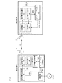
ここで図2は、本発明の第2の実施形態で、この実施形態が、上記した第1の実施形態とブロック構成上異なる点は、無線機Aには受信電力計測部8が設けられ、無線機Bには送信電力制御部14がもけられている点にあり、その他の点は同じである。
そして、これにより、まず、無線機A側では、無線機Bの送信部B10から出力される高周波送信電力の強度レベルBPを知ることができるようにしてあり、このため、無線機B側では、送信部10から出力される高周波送信電力を制御するため、送信電力制御部14から出力されている強度レベルBPのデータ、つまり強度レベルデータBPDが送信データ生成部13に入力され、これにより無線機Bから無線機Aに伝送すべきデータの、例えば無線フレームにヘッダー部分に、この強度レベルデータBPDが挿入され、送信信号に重畳されて伝送され中継されるようになっている。
Next, another embodiment of the present invention will be described.
Here, FIG. 2 is a second embodiment of the present invention. The difference of this embodiment from the first embodiment described above in terms of the block configuration is that the wireless device A is provided with a received
Thus, first, on the wireless device A side, it is possible to know the intensity level BP of the high-frequency transmission power output from the transmission unit B10 of the wireless device B. For this reason, on the wireless device B side, In order to control the high-frequency transmission power output from the
このとき、無線機B側の送信電力制御部14は、この強度レベルデータBPDを送信部B10に送信電力の制御信号として供給し、送信電力が制御されるようにしてあり、この結果、この強度レベルデータBPDが表わす値は、送信部A3から実際に出力される高周波電力を表わすものとなっている。つまり、送信部B10から実際に出力される高周波電力を実送信電力BPR とすると、BPR =BPDと看做せる。
また、ここで送信部B10が出力可能な高周波電力の最大値を最大送信電力BPM とすると、これは言うまでもなく設計仕様で決まる定格値のことであり、従って、予め定数として知ることができる。
At this time, the transmission power control unit 14 on the wireless device B side supplies the strength level data BPD to the transmission unit B10 as a transmission power control signal so that the transmission power is controlled. The value represented by the level data BPD represents the high-frequency power that is actually output from the transmission unit A3. That is, assuming that the high frequency power actually output from the transmission unit B10 is the actual transmission power BP R, it can be considered that BP R = BPD.
Moreover, when now to the maximum value of the transmission portion B10 can output high-frequency power to the maximum transmission power BP M, which is that of the rated value determined by the course design specifications, therefore, can be known in advance as a constant.
そこで、無線機A側のモニター電圧演算部6は、受信部A4から入力された強度レベルデータBPDを実際に無線機B側の送信部B10から出力される実送信電力BPR とし、これと、同じく入力された受信強度レベルBL及び定数として与えられる最大送信電力BPM とから次の(2)式により、アナログ強度レベル電圧Mを算出する。
M=BL−BPR +BPM …………(2)
このときも実送信電力BPR と最大送信電力BPM については、「BPR≦BPM」の関係にあることは、言うまでもない。
Therefore, the
M = BL-BP R + BP M (2)
Needless to say, the actual transmission power BP R and the maximum transmission power BP M are also in the relationship of “BP R ≦ BP M ”.
このようにして、モニター電圧演算部6によりアナログ強度レベル電圧Mを算出した場合、この図2の実施形態においても、条件「BPR<BPM」が成立している間、つまり無線機B側の送信部B10から、その定格送信電力より低い値の電力が送信されている間は、端子部7から出力されるモニター電圧は、無線機B側の受信部B11での受信電力相当値よりも大きな値として得られ、しかも、この場合、実送信電力APR が減算されていることから、実送信電力APR の変動が相殺され、この結果、双方の無線機A、Bで送信レベル動的制御機能が働いているときでも容易に指向性アンテナ1の最大利得点を見付け出すことができ、高精度のアラインメント調整を確実に得ることができる。
In this way, when the analog intensity level voltage M is calculated by the monitor
このときの指向性アンテナ1のアラインメント調整も上記した場合と同じで、作業者がテスタのメータを見ながら指向性アンテナ1を動かして少しづつ向きを変え、メータの振れが最大になった位置でアンテナの向きを固定してやれば、指向性アンテナ1の最大利得点に指向方向が正しく設定され、アラインメント調整が完了されることになる。
ところで、以上は、説明を判り易くするため、無線機Aと無線機Bの構成を分けて示したが、一般的には双方の無線機が同等の構成を有しているが通例であり、従って、無線機B側でも同様に指向性アンテナのアラインメント調整が可能なことは言うまでもない。
The alignment adjustment of the directional antenna 1 at this time is also the same as described above, and the operator moves the directional antenna 1 while looking at the meter of the tester and changes the direction little by little, so that the deflection of the meter becomes maximum. If the direction of the antenna is fixed, the directivity direction is correctly set at the maximum gain point of the directional antenna 1, and the alignment adjustment is completed.
By the way, in order to make the explanation easy to understand, the configurations of the wireless device A and the wireless device B are shown separately. Generally, both wireless devices have the same configuration, but it is usual. Therefore, it goes without saying that the alignment adjustment of the directional antenna can be similarly performed on the wireless device B side.
次に、本発明の更に他の実施形態について説明する。
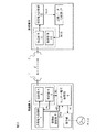
図3は、本発明の第3の実施形態で、この実施形態が、上記した第1の実施形態とブロック構成上異なる点は、無線機Aに目標値設定部9が設けられている点だけで、その他の点は同じである。
この目標値設定部9は、指向性アンテナ1のアラインメント調整に目標範囲を設定する働きをするもので、このため目標範囲を表わす電圧、つまり目標値VXを発生し、この目標値VXはモニター電圧演算部6に入力され、アナログ強度レベル電圧Mの演算に使用されるようになっている。
Next, still another embodiment of the present invention will be described.
FIG. 3 shows a third embodiment of the present invention. This embodiment is different from the first embodiment in the block configuration only in that a target value setting unit 9 is provided in the wireless device A. The other points are the same.
The target value setting unit 9 functions to set a target range for alignment adjustment of the directional antenna 1, and therefore generates a voltage representing the target range, that is, a target value VX. The target value VX is a monitor voltage. The signal is input to the
ここで、指向性アンテナの指向特性について説明すると、これは、一般に最大利得点の近傍では緩やかな特性になっている。従って、アラインメント調整を高精度に設定しようとすると、メータの振れが極大値付近あるとき、僅かな振れの変化に応じてアンテナを細かく動かす必要が有り、作業に根気が必要で時間も多く掛ってしまう。
一方、実用上は、それ程、高精度に設定しなくても充分な場合があり、この場合は、或る精度範囲内に収めて設定してやればよい。
そこで、この第3の実施形態では、上記した目標値VXを設定し、これにより上記した精度範囲内に収めることができるようにしたものである。
Here, the directivity characteristics of the directional antenna will be described. In general, the directivity characteristics are gentle in the vicinity of the maximum gain point. Therefore, when trying to set the alignment adjustment with high accuracy, when the meter shake is near the maximum value, it is necessary to move the antenna finely according to slight changes in the shake, and it takes time and effort to work. End up.
On the other hand, there is a case where it is not necessary to set the accuracy so high in practical use. In this case, the setting may be made within a certain accuracy range.
Therefore, in the third embodiment, the above-described target value VX is set so as to be within the above-described accuracy range.
従って、モニター電圧演算部6は、送信電力制御部5から入力された送信電力制御信号ATLを実際に送信部A3から出力される実送信電力APR とし、これと、同じく入力された受信強度レベルBL及び定数として与えられる最大送信電力APM 、それに目標値VXから次の(3)式により、アナログ強度レベル電圧Mを算出する。
M=BL−APR +APM −VX…………(3)
このとき、実送信電力APR と最大送信電力APM について「APR≦APM」の関係にあることに変わりはない。
Therefore, the monitor
M = BL-AP R + AP M −VX (3)
At this time, the actual transmission power AP R and the maximum transmission power AP M are still in the relationship of “AP R ≦ AP M ”.
従って、この第3の実施形態によっても、双方の無線機A、Bで送信レベル動的制御機能が働いているときに確実に指向性アンテナの指向方向が電波の送信源に正しく向い、指向性アンテナの最大利得点が見付け出せることになる点は、第1の実施形態と同じであるが、このとき、アナログ強度レベル電圧Mが目標値VXの差分で与えられるので、アラインメント調整について、その精度が目標値VXで設定されている範囲内に収まったとき、アナログ強度レベル電圧Mが0になるようにすればよいので、アラインメント調整が簡素化でき、作業に必要な時間が短縮できる。 Therefore, also in the third embodiment, when the transmission level dynamic control function is working in both the radios A and B, the directivity direction of the directional antenna is surely correctly directed to the radio wave transmission source, and the directivity The point that the maximum gain point of the antenna can be found is the same as in the first embodiment. At this time, the analog intensity level voltage M is given by the difference of the target value VX. When the value falls within the range set by the target value VX, the analog intensity level voltage M may be set to 0, so that the alignment adjustment can be simplified and the time required for the work can be shortened.
1:指向性アンテナ(無線機Aの指向性アンテナ)
2:指向性アンテナ(無線機Bの指向性アンテナ)
3:送信部A
4:受信部A
5:送信電力制御部
6:モニター電圧演算部
7:端子部
8:受信電力計測部
9:目標値設定部
10:送信部B
11:受信部B
12:受信電力計測部
13:送信データ生成部
14:送信電力計測部。
A:
C:伝送経路
1: Directional antenna (Directional antenna for Radio A)
2: Directional antenna (directional antenna for radio B)
3: Transmitter A
4: Receiver A
5: Transmission power control unit 6: Monitor voltage calculation unit 7: Terminal unit 8: Received power measurement unit 9: Target value setting unit 10: Transmission unit B
11: Receiver B
12: Received power measurement unit 13: Transmission data generation unit 14: Transmission power measurement unit
A:
C: Transmission path
Claims (1)
前記他方の無線局には、
受信電力を計測し、計測した受信電力値を当該他方の無線局から前記一方の無線局に送信する信号に重畳させて伝送する送信データ生成部を設け、
前記一方の無線局には、
前記他方の無線局から伝送された前記受信電力値に応じて送信電力制御信号を発生し、当該一方の無線局から送信される送信電力を前記送信電力制御信号に応じて制御する送信電力制御部と、当該一方の無線局の受信部から入力される電界強度レベルを前記送信電力制御部より出力される前記送信電力制御信号により補正し、アナログ強度レベル電圧を算出するモニター電圧演算部とを設け、
前記一方の無線局において、前記アナログ強度レベル電圧の値から前記指向性アンテナのアラインメント調整が得られるように構成したことを特徴とする無線通信システム。 In a wireless communication system for relay using a directional antenna for transmission and reception of radio waves in one and the other wireless station,
In the other radio station ,
A reception data value is measured, and a transmission data generation unit is provided for transmitting the measured reception power value by superimposing the signal to be transmitted from the other radio station to the one radio station,
The one radio station includes
A transmission power control unit that generates a transmission power control signal according to the received power value transmitted from the other radio station, and controls the transmission power transmitted from the one radio station according to the transmission power control signal And a monitor voltage calculation unit that corrects the electric field strength level input from the receiving unit of the one radio station with the transmission power control signal output from the transmission power control unit, and calculates an analog strength level voltage. ,
Wireless communication system, characterized in that in the one radio station, configured as alignment adjustment of the directional antenna from the value of the analog intensity-level voltage is obtained.
Priority Applications (1)
| Application Number | Priority Date | Filing Date | Title |
|---|---|---|---|
| JP2008155517A JP5317543B2 (en) | 2008-06-13 | 2008-06-13 | Wireless communication system |
Applications Claiming Priority (1)
| Application Number | Priority Date | Filing Date | Title |
|---|---|---|---|
| JP2008155517A JP5317543B2 (en) | 2008-06-13 | 2008-06-13 | Wireless communication system |
Related Child Applications (1)
| Application Number | Title | Priority Date | Filing Date |
|---|---|---|---|
| JP2013141430A Division JP2013219833A (en) | 2013-07-05 | 2013-07-05 | Radio communication system |
Publications (2)
| Publication Number | Publication Date |
|---|---|
| JP2009302939A JP2009302939A (en) | 2009-12-24 |
| JP5317543B2 true JP5317543B2 (en) | 2013-10-16 |
Family
ID=41549369
Family Applications (1)
| Application Number | Title | Priority Date | Filing Date |
|---|---|---|---|
| JP2008155517A Active JP5317543B2 (en) | 2008-06-13 | 2008-06-13 | Wireless communication system |
Country Status (1)
| Country | Link |
|---|---|
| JP (1) | JP5317543B2 (en) |
Families Citing this family (3)
| Publication number | Priority date | Publication date | Assignee | Title |
|---|---|---|---|---|
| JP5548598B2 (en) * | 2010-11-30 | 2014-07-16 | 日田アンテナ工事株式会社 | Communications system |
| JP5979926B2 (en) * | 2012-03-19 | 2016-08-31 | 株式会社日立国際電気 | Wireless device |
| JP2022171137A (en) * | 2021-04-30 | 2022-11-11 | パナソニックホールディングス株式会社 | WIRELESS POWER TRANSMISSION SYSTEM AND WIRELESS POWER TRANSMISSION METHOD |
Family Cites Families (5)
| Publication number | Priority date | Publication date | Assignee | Title |
|---|---|---|---|---|
| JPH09200115A (en) * | 1996-01-23 | 1997-07-31 | Toshiba Corp | Antenna directivity control method for wireless base station in wireless communication system and variable directivity antenna |
| JP3665628B2 (en) * | 2001-08-07 | 2005-06-29 | 株式会社東芝 | Wireless communication system and wireless terminal device |
| JP3774426B2 (en) * | 2001-09-28 | 2006-05-17 | 株式会社東芝 | Base station apparatus, communication system, and frame transmission method |
| JP2004201137A (en) * | 2002-12-19 | 2004-07-15 | Ntt Docomo Inc | Directional beam communication system, directional beam communication method, base station, and control device |
| JP2009118163A (en) * | 2007-11-06 | 2009-05-28 | Hitachi Kokusai Electric Inc | Wireless transmission device |
-
2008
- 2008-06-13 JP JP2008155517A patent/JP5317543B2/en active Active
Also Published As
| Publication number | Publication date |
|---|---|
| JP2009302939A (en) | 2009-12-24 |
Similar Documents
| Publication | Publication Date | Title |
|---|---|---|
| US5564075A (en) | Method and system for controlling the power at which an access packet is sent by a mobile in a mobile radio system | |
| US6819936B2 (en) | Automatic gain setting in a cellular communications system | |
| KR101751630B1 (en) | Signal adjusting method, apparatus, and cell | |
| US9699010B2 (en) | Wireless communication apparatus | |
| CN105375935A (en) | Compensator module for a transceiver unit, radio system and method of operating thereof | |
| JP2008216084A (en) | Signal source position estimation method and propagation path state estimation method | |
| JP5317543B2 (en) | Wireless communication system | |
| CN100508659C (en) | Power amplifying system and method | |
| US11063351B2 (en) | Antenna angle adjustment device, antenna angle adjustment method, and communications device | |
| JP2013219833A (en) | Radio communication system | |
| JP2012137478A (en) | Distance measurement device and distance correction means | |
| US8060007B2 (en) | Adaptive crosspole technique | |
| JP6431775B2 (en) | Phase detector and satellite repeater | |
| KR101756807B1 (en) | Apparatus and method for controlling transmission power in a wireless communication system | |
| JP6330172B2 (en) | Wireless communication system and wireless communication apparatus | |
| KR101545752B1 (en) | Apparatus and method for compensating cable loss of a base station in wireless communication system | |
| KR100328571B1 (en) | An apparatus for compensating a delay time of wireless communication systems | |
| CN111211823B (en) | Method and device for switching transmitting antenna, storage medium and electronic equipment | |
| JP2017059933A (en) | Communication system, base station, and antenna control method | |
| KR101905434B1 (en) | Apparatus for measuring passive intermodulation distortion signal and method for using the same | |
| KR101469103B1 (en) | Interference cancellation repeater and repeating method thereof | |
| KR20020068967A (en) | Apparatus for measuring antenna standing wave ratio | |
| JP4680121B2 (en) | Signal transmission system | |
| KR100596724B1 (en) | Synchronizer and method for time division redundancy based small RF repeater | |
| KR20180033998A (en) | Base station antenna and remote electric tilt |
Legal Events
| Date | Code | Title | Description |
|---|---|---|---|
| A621 | Written request for application examination |
Free format text: JAPANESE INTERMEDIATE CODE: A621 Effective date: 20110602 |
|
| A977 | Report on retrieval |
Free format text: JAPANESE INTERMEDIATE CODE: A971007 Effective date: 20121113 |
|
| A131 | Notification of reasons for refusal |
Free format text: JAPANESE INTERMEDIATE CODE: A131 Effective date: 20121120 |
|
| A521 | Request for written amendment filed |
Free format text: JAPANESE INTERMEDIATE CODE: A523 Effective date: 20130117 |
|
| TRDD | Decision of grant or rejection written | ||
| A01 | Written decision to grant a patent or to grant a registration (utility model) |
Free format text: JAPANESE INTERMEDIATE CODE: A01 Effective date: 20130618 |
|
| A61 | First payment of annual fees (during grant procedure) |
Free format text: JAPANESE INTERMEDIATE CODE: A61 Effective date: 20130709 |
|
| R150 | Certificate of patent or registration of utility model |
Ref document number: 5317543 Country of ref document: JP Free format text: JAPANESE INTERMEDIATE CODE: R150 Free format text: JAPANESE INTERMEDIATE CODE: R150 |
|
| R250 | Receipt of annual fees |
Free format text: JAPANESE INTERMEDIATE CODE: R250 |
|
| R250 | Receipt of annual fees |
Free format text: JAPANESE INTERMEDIATE CODE: R250 |
|
| R250 | Receipt of annual fees |
Free format text: JAPANESE INTERMEDIATE CODE: R250 |
|
| R250 | Receipt of annual fees |
Free format text: JAPANESE INTERMEDIATE CODE: R250 |
|
| R250 | Receipt of annual fees |
Free format text: JAPANESE INTERMEDIATE CODE: R250 |
|
| R250 | Receipt of annual fees |
Free format text: JAPANESE INTERMEDIATE CODE: R250 |
|
| R250 | Receipt of annual fees |
Free format text: JAPANESE INTERMEDIATE CODE: R250 |
|
| R250 | Receipt of annual fees |
Free format text: JAPANESE INTERMEDIATE CODE: R250 |
|
| R250 | Receipt of annual fees |
Free format text: JAPANESE INTERMEDIATE CODE: R250 |
|
| S531 | Written request for registration of change of domicile |
Free format text: JAPANESE INTERMEDIATE CODE: R313531 |
|
| S533 | Written request for registration of change of name |
Free format text: JAPANESE INTERMEDIATE CODE: R313533 |
|
| R350 | Written notification of registration of transfer |
Free format text: JAPANESE INTERMEDIATE CODE: R350 |
|
| R250 | Receipt of annual fees |
Free format text: JAPANESE INTERMEDIATE CODE: R250 |