JP5317536B2 - Wearable human support device - Google Patents
Wearable human support device Download PDFInfo
- Publication number
- JP5317536B2 JP5317536B2 JP2008140502A JP2008140502A JP5317536B2 JP 5317536 B2 JP5317536 B2 JP 5317536B2 JP 2008140502 A JP2008140502 A JP 2008140502A JP 2008140502 A JP2008140502 A JP 2008140502A JP 5317536 B2 JP5317536 B2 JP 5317536B2
- Authority
- JP
- Japan
- Prior art keywords
- wearer
- linear transmission
- support device
- drive
- person support
- Prior art date
- Legal status (The legal status is an assumption and is not a legal conclusion. Google has not performed a legal analysis and makes no representation as to the accuracy of the status listed.)
- Active
Links
Images


Landscapes
- Manipulator (AREA)
- Prostheses (AREA)
Description
本発明は装着型人支援装置に係り、特に神経系統が麻痺して筋肉を思うように動作させることができないといった障害を有する被装着者に装着され、身体障害を有する被装着者の動作補助または機能回復補助を行なうよう構成された装着型人支援装置に関する。 The present invention relates to a wearable person support apparatus, and is particularly worn by a wearable person who has a disorder such that the nervous system is paralyzed and the muscles cannot be operated as desired, and the operation assistance or The present invention relates to a wearable person support device configured to perform function recovery assistance.
例えば、顔面表情麻痺などのように神経系統が麻痺した人、あるいは脳に障害ある高次脳機能障害の人は、自分の筋力を自分の意思でコントロールすることが難しくなっており、外部からの補助があることで障害のある身体の一部を動作させることが可能になる場合がある。 For example, people with paralysis of the nervous system such as facial expression paralysis, or people with higher brain dysfunction who have a brain disorder, have difficulty in controlling their muscle strength with their own will. With assistance, it may be possible to move a part of the disabled body.
以下、顔面表情麻痺を有する被装着者に対する動作補助または機能回復補助を行なう場合を例に挙げて説明する。顔面表情麻痺とは、顔面表情筋の活動低下による症状のことであり、主な症状としては、顔の右半分または左半分の筋肉が突然動かなくなり、顔の変形(左右非対称のゆがみ)が現れる神経障害である。この顔面表情麻痺は、一時的な麻痺と完全麻痺とがあり、重度の症状になると、口の形が崩れて食べ物を摂取することが難しくなり、口から食べ物が溢れたりすることもある。また、顔面表情麻痺が軽度の場合でも、パニック障害や不安による心的障害の影響が大きくなってうつ症状を招くことが多い。 Hereinafter, a case where operation assistance or function recovery assistance is performed on a wearer having facial expression paralysis will be described as an example. Facial palsy is a symptom caused by a decrease in facial facial muscle activity, and the main symptoms are suddenly dysfunctional muscles in the right or left half of the face, and facial deformation (asymmetrical distortion). It is a neurological disorder. This facial expression paralysis has temporary paralysis and complete paralysis, and if it becomes a severe symptom, the shape of the mouth collapses and it becomes difficult to eat food, and food may overflow from the mouth. Even if facial facial palsy is mild, the effects of mental disorder due to panic disorder or anxiety are often increased, leading to depressive symptoms.
この種の機能障害を回復するための装置としては、顔面表情麻痺の人の顔に電極を装着し、ビデオ画像に連動して電極に電気的信号を印加することで顔の表情筋に筋力を発生させてビデオ画像を見て浮かぶ感情に合った表情となるように表情筋を動かす訓練(リハビリテーション)を行なわせる装置がある(例えば、特許文献1参照)。
しかしながら、上記のような従来の装置は、顔の表情筋に電気信号を印加することで感情に応じた表情筋を動作させて感情に合った表情を表現できるように訓練するものであり、ビデオ画像に応じた感情の変化を正確に推測することが難しく、且つ表情筋を電気的に動作させてもその表情が本人の意思を正確に反映しているのかを判断することが難しかった。 However, the conventional apparatus as described above trains the facial expression muscles so that the facial expression muscles can be expressed by applying an electrical signal to the facial expression muscles to operate the facial expression muscles according to the emotions. It was difficult to accurately guess the emotional change according to the image, and it was difficult to judge whether the facial expression accurately reflected the intention of the person even if the facial muscles were electrically operated.
また、顔の表情筋以外の部分(例えば、手の指等の比較的小さい力で動作する箇所)でも、神経系統が麻痺していると、筋肉を覆う皮膚に電極を貼着して電気信号を印加しても筋肉から本人の意思に応じた駆動力を得ることが難しかった。 In addition, if the nervous system is also paralyzed in parts other than facial facial muscles (for example, parts that move with a relatively small force, such as the fingers of a hand), electrodes are attached to the skin that covers the muscles and an electrical signal is generated. It was difficult to obtain the driving force according to the intention of the person from the muscles even when applied.
そこで、本発明は上記事情に鑑み、上記課題を解決した装着型人支援装置を提供することを目的とする。 Therefore, in view of the above circumstances, an object of the present invention is to provide a wearable person support device that solves the above-described problems.
上記課題を解決するため、本発明は以下のような手段を有する。
(1) 本発明は、一端が被装着者の皮膚の被駆動領域に貼り付けられる線状伝達部材と、
該線状伝達部材の他端に結合され、前記被駆動部分から離間した他の部分に装着される駆動部と、
前記線状伝達部材を前記被装着者の皮膚に貼着させる貼着部材と、
当該被装着者の意思に応じた指令信号を生成する指令信号生成手段と、
該指令信号生成手段から出力された指令信号に基づいて前記駆動部による駆動力を制御する制御部と、
を備え、
前記駆動部は、駆動力を発生させる際に駆動音を生じない無音方式のアクチュエータであることにより、上記課題を解決するものである。
(2) 本発明は、請求項1に記載の装着型人支援装置であって、
前記線状伝達部材は、断面が微細かつ扁平形状に形成されることにより、上記課題を解決するものである。
(3) 本発明は、請求項1又は2に記載の装着型人支援装置であって、
前記線状伝達部材は、温度に応じた形状に変化する形状記憶合金により形成され、
前記駆動部は、
前記線状伝達部材に連結され、温度に応じた形状に変化する形状記憶合金と、
前記形状記憶合金の温度を調整する温度調整手段と、
からなることにより、上記課題を解決するものである。
(4) 本発明は、請求項1乃至3の何れかに記載の装着型人支援装置であって、
前記線状伝達部材の一端を前記被装着者の顔の表情筋を覆う皮膚に貼着し、
前記駆動部及び前記制御部を前記被装着者の後頭部に配したことにより、上記課題を解決するものである。
(5) 本発明は、請求項1乃至4の何れかに記載の装着型人支援装置であって、
前記指令信号生成手段は、前記被装着者の筋肉を動作させるための生体信号を検出する生体信号検出手段であり、
前記制御部は、前記生体信号検出手段により検出された生体信号に基づき前記被装着者が行なうとする顔の表情に応じた駆動制御信号を生成し、当該駆動制御信号を前記駆動部に印加することにより、上記課題を解決するものである。
(6) 本発明は、請求項1乃至4の何れかに記載の装着型人支援装置であって、
前記指令信号生成手段は、前記被装着者が操作するコントローラであり、
前記制御部は、前記コントローラからの指令信号に応じた駆動制御信号を生成し、当該駆動制御信号を前記駆動部に印加することにより、上記課題を解決するものである。
In order to solve the above problems, the present invention has the following means.
(1) The present invention provides a linear transmission member having one end attached to a driven region of a wearer's skin;
A drive unit coupled to the other end of the linear transmission member and attached to another part spaced from the driven part;
An adhesive member for attaching the linear transmission member to the skin of the wearer; and
Command signal generating means for generating a command signal according to the intention of the wearer;
A control unit for controlling the driving force by the driving unit based on the command signal output from the command signal generating means;
Bei to give a,
The drive unit solves the above problems by being a silent actuator that does not generate a drive sound when generating a drive force.
( 2 ) The present invention is the wearable person support device according to claim 1 ,
The said linear transmission member solves the said subject, when a cross section is formed in a fine and flat shape.
( 3 ) The present invention is the wearable person support device according to claim 1 or 2 ,
The linear transmission member is formed of a shape memory alloy that changes into a shape according to temperature,
The drive unit is
A shape memory alloy connected to the linear transmission member and changing into a shape according to temperature;
Temperature adjusting means for adjusting the temperature of the shape memory alloy;
The above-mentioned problem is solved by comprising.
( 4 ) The present invention is the wearable person support device according to any one of claims 1 to 3 ,
Adhering one end of the linear transmission member to the skin covering the facial expression muscle of the wearer,
The said subject is solved by arranging the said drive part and the said control part in the back head of the said to-be-weared person.
( 5 ) The present invention is the wearable person support device according to any one of claims 1 to 4 ,
The command signal generation means is a biological signal detection means for detecting a biological signal for operating the muscle of the wearer,
The control unit generates a drive control signal corresponding to a facial expression to be performed by the wearer based on the biological signal detected by the biological signal detection unit, and applies the drive control signal to the drive unit. This solves the above-mentioned problem.
( 6 ) The present invention is the wearable person support device according to any one of claims 1 to 4 ,
The command signal generating means is a controller operated by the wearer,
The said control part solves the said subject by producing | generating the drive control signal according to the command signal from the said controller, and applying the said drive control signal to the said drive part.
本発明によれば、線状伝達部材を被装着者の皮膚に貼着し、当該被装着者の意思に応じて指令信号生成手段から出力された指令信号に基づいて駆動部による駆動力を制御して線状伝達部材を駆動するため、当該被装着者の意思に合った駆動力を被装着者の被駆動部分に伝達して当該被装着者の麻痺した動作を正確に補助することが可能になる。さらに、駆動部が、駆動力を発生させる際に駆動音を生じない無音方式のアクチュエータであるため、被装着者の頭部に装着された場合でも、動作時の不快感を無くすことができる。
According to the present invention, the linear transmission member is attached to the wearer's skin, and the driving force by the drive unit is controlled based on the command signal output from the command signal generating means according to the wearer's intention. In order to drive the linear transmission member, it is possible to accurately assist the wearer's paralyzed movement by transmitting a driving force suitable for the wearer's intention to the driven portion of the wearer. become. Furthermore, since the drive unit is a silent actuator that does not generate a drive sound when generating a drive force, even when the drive unit is mounted on the head of the wearer, discomfort during operation can be eliminated.
また、本発明によれば、被装着者が顔面表情麻痺の場合には、顔の表情筋を覆う皮膚に線状伝達部材の一端を貼着して顔の表情を被装着者の意思に応じて表現することが可能になり、被装着者の感情や意思に合った顔表情の作成を補助することができる。 Further, according to the present invention, when the wearer is a facial expression paralysis, one end of the linear transmission member is attached to the skin covering the facial expression muscle, and the facial expression is determined according to the wearer's intention. And can assist in the creation of facial expressions that match the emotions and intentions of the wearer.
さらに、本発明によれば、顔面表情麻痺、あるいは高次脳機能障害の人の機能回復訓練(リハビリテーション)を支援することも可能になる。 Furthermore, according to the present invention, it is possible to support functional recovery training (rehabilitation) for a person with facial expression paralysis or higher brain dysfunction.
以下、図面を参照して本発明を実施するための最良の形態について説明する。 The best mode for carrying out the present invention will be described below with reference to the drawings.
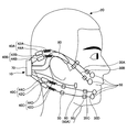
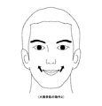
図1は本発明による装着型人支援装置の一実施例を被装着者に装着した状態を示す図である。以下の本実施例においては、被装着者が顔面の右半分が麻痺した場合を例に挙げて説明する。 FIG. 1 is a view showing a state in which a wearable person support apparatus according to an embodiment of the present invention is worn on a wearer. In the following embodiment, a case where the wearer is paralyzed on the right half of the face will be described as an example.
顔面表情麻痺及び高次脳機能障害を有する人は、自らの試行錯誤により麻痺していた運動機能を回復させる認知運動療法によって筋肉の動きが徐々に回復することが可能になる。本発明の装着型人支援装置は、強制的に外部から筋肉を動作させるものではなく、被装着者自身の意思に応じて筋肉の動作を補助することで認知運動療法を促進することを目的としている。 A person with facial expression paralysis and higher brain dysfunction can gradually recover muscle movement by cognitive exercise therapy that restores the motor function that has been paralyzed by trial and error. The wearable person support device of the present invention is not intended to force the muscles to be operated from the outside, but to promote cognitive exercise therapy by assisting the movement of the muscles according to the wearer's own intention. Yes.
図1に示されるように、装着型人支援装置10は、顔面表情麻痺を有する被装着者20に装着されて当該被装着者20の認知運動療法を補助する装置である。装着型人支援装置10は、一端が被装着者20の被駆動部分となる皮膚に貼着される線状伝達部材30A〜30Dと、線状伝達部材30A〜30Dの他端に結合され、被駆動部分から離間した他の部分に装着される駆動部40A〜40Dと、線状伝達部材30A〜30Dを被装着者20の皮膚に貼着させる貼着部材50と、当該被装着者の意思に応じた指令信号を生成する指令信号生成手段60と、指令信号生成手段60から出力された指令信号に基づいて駆動部40A〜40Dに駆動力制御信号を出力する制御ユニット70とから構成されている。
As shown in FIG. 1, the wearable
制御ユニット70は、被装着者20の両耳から後頭部に装着されたフレーム80に保持されている。フレーム80は、両端が逆U字状に曲げられており、めがねのように両耳に掛止されることにより制御ユニット70を後頭部の後方に保持することが可能になる。
The
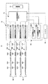
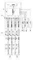
図2は装着型人支援装置10のシステム構成図である。図2に示されるように、本実施例において、線状伝達部材30A〜30Dは、4本が並列に配されているが、4本に限るものではなく、1本〜3本でも良いし、あるいは、可能であれば5本〜6本を配するようにしても良い。
FIG. 2 is a system configuration diagram of the wearable
線状伝達部材30A〜30Dは、断面形状が扁平(皮膚に当接する側が幅広になる)に形成されており、且つ厚さが髪の毛程度の微細形状(例えば、幅が0.5mm〜1mm、厚さが0.1mm〜2mm程度)に形成されている。そのため、線状伝達部材30A〜30Dは、顔の皮膚表面から大きく突出しないように密着させることが可能になる。
Each of the
線状伝達部材30A〜30Dの材質として、剛性を有すると共に、腐食しにくいステンレス材またはピアノ線などの金属ワイヤ、あるいは金属ワイヤの外周に炭素繊維で編んだ紐状体を巻き付けた複合材ワイヤなどが用いられる。
As a material for the
また、各線状伝達部材30A〜30Dは、夫々樹脂材からなる保護チューブ32A〜32Dに挿通されており、長手方向に伸縮する中間部分が顔面の皮膚に直接接しないように装着される。保護チューブ32A〜32Dは、断面形状が線状伝達部材30A〜30Dの断面形状に対応した微細な扁平形状に形成された中空部材からなる。
Each of the
また、線状伝達部材30A〜30Dの一端は、顔面の被駆動部分となる任意の箇所の皮膚表面に粘着テープまたは粘着性ゲルなどからなる貼着部材50により貼着される。本実施例の場合、線状伝達部材30A〜30Dの一端は、顔面の表情筋(詳細は後述する)を覆う皮膚の表面に貼着される。
Further, one end of each of the
尚、線状伝達部材30A〜30D及び保護チューブ32A〜32Dは、被装着者20の皮膚の色と同系色に塗装または着色されており、皮膚と同じ色であるので、外観的に目立たないように装着することが可能である。さらに、被装着者20の顔及び線状伝達部材30A〜30D及び保護チューブ32A〜32Dの表面を化粧することで、皮膚と線状伝達部材30A〜30D及び保護チューブ32A〜32Dとが一体化したように見せることも可能である。
The
線状伝達部材30A〜30Dの他端は、駆動部40A〜40Dに連結されている。本実施例の駆動部40A〜40Dは、夫々形状記憶合金42A〜42Dと、形状記憶合金の温度を調整する温度調整部44A〜44Dとからなる。
The other ends of the
形状記憶合金42A〜42Dは、例えば、チタンとニッケルの合金等からなり、変形された形状が温度によって元の形状に戻る性質を有する。また、形状記憶合金42A〜42Dは、温度に応じて伸縮するコイル状に形成されており、且つある温度(変態点)以下で変形しても、その温度以上に加熱すると元の形状に戻る性質を有するため、冷却されることで縮み方向に変位して線状伝達部材30A〜30Dに駆動力としての引張り力を伝達し、加温されることで膨張方向に変位して線状伝達部材30A〜30Dを元の形状に復帰させる復元力を伝達することができる。本実施例の駆動部40A〜40Dは、例えば、1cmの変位量を1Hzで動作させることが可能である。
The
温度調整部44A〜44Dは、例えば、2種類の金属の接合部に電流を流すと、片方の金属からもう片方へ熱が移動するというペルティエ効果を利用した板状の熱電変換素子からなる。温度調整部44A〜44Dは、装着時には、形状記憶合金42A〜42Dを効率良く加温または冷却するように形状記憶合金42A〜42Dの近傍に取り付けられる。
The
この形状記憶合金42A〜42D及び温度調整部44A〜44Dは、動作音を発生しない無音駆動方式の駆動部であり、特に被装着者20の頭部に装着されることから、動作時の不快感を無くすためには、動作音が発生しないことが重要である。
The
また、駆動部40A〜40Dとしては、上記形状記憶合金42A〜42D、温度調整部44A〜44D以外の構成のアクチュエータ、例えば、線熱膨張係数の異なる2種類の金属を重ね合わせたバイメタル、あるいは電磁力や静電気、空気圧等を駆動源とするアクチュエータでも駆動音(モータ音や機械的伝達機構の動作音等)を発生しない構成のものであればよい。
Further, as the
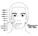
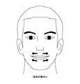
図3に示されるように、指令信号生成手段60は、被装着者20の顔面神経が集中している耳と顎の間に位置する被検出領域に貼着される生体信号検出センサ60A,60Bを有する。この生体信号検出センサ60A,60Bは、被装着者20の脳から顔の表情筋に送出された神経伝達信号を生体信号として検出する電極からなり、被装着者20の顔面の左右対称となる顔面神経信号検出領域(図4参照)に貼着される。従って、被装着者20が顔の表情を変化させようと思考した場合、生体信号検出センサ60A,60Bは、脳から顔の表情筋に伝達された神経伝達信号(生体電位)を検出し、制御ユニット70に神経伝達信号を出力する。
As shown in FIG. 3, the command signal generation means 60 is a biological
制御ユニット70は、データベースが格納された記憶部72と、指令信号生成手段60によって検出された神経伝達信号に基づいて駆動制御信号を演算する中央処理装置(CPU:Central Processing Unit)74と、中央処理装置74により演算された各駆動制御信号を温度調整部44A〜44Dに供給する駆動制御信号出力部76A〜76Dとを有する。また、制御ユニット70には、携帯用電源としてのバッテリ90から電源供給される。
The
記憶部72は、ROM(Read Only Memory)またはRAM(Random Access Memory)よりなり、予め各顔表情に応じた駆動部40A〜40Dに対する駆動制御信号と駆動制御信号の各値に対応する形状記憶合金42A〜42Dの変位量(または駆動時間)及び駆動力とが予め登録されたデータベースが格納されている。
The
中央処理装置74は、生体信号検出センサ60A,60Bによって検出された神経伝達信号に基づいて記憶部72のデータベースから駆動制御信号を抽出し、当該駆動制御信号を温度調整部44A〜44Dに供給する。被装着者20は、顔の表情を変化させようと思考すると、脳から顔の表情筋に神経伝達信号が伝達される。
The
従って、制御ユニット70は、脳から顔の表情筋に伝達される神経伝達信号を生体信号検出センサ60A,60Bによって検出されると、この神経伝達信号に応じた駆動制御信号を生成して温度調整部44A〜44Dに供給する。そのため、当該被装着者20が思考した表情に応じた駆動力が駆動部40A〜40Dによって生成され、この駆動力及び変位量が線状伝達部材30A〜30Dの夫々に伝達されて被装着者20の顔面右半分の表情筋を覆う皮膚が4箇所で駆動される。
Therefore, when the nerve signal transmitted from the brain to the facial expression muscle is detected by the biological
ここで、図4を参照して被装着者20の顔面表情筋について説明する。人の顔面には、多くの表示筋があり、例えば、図4中破線で示されるように、皺眉筋101、眼輪筋102、小頬骨筋103、大頬骨筋104、頬筋105、笑筋106、咬筋107、口角下制筋108、下唇下制筋109、頤筋110等がある。
Here, the facial expression muscles of the
本実施例においては、4本の線状伝達部材30A〜30Dのうち上側の2本の線状伝達部材30A,30Bは、夫々小頬骨筋103、大頬骨筋104に沿うように貼着部材50により貼着され、小頬骨筋103、大頬骨筋104を覆う皮膚に端部(被駆動部分)が貼着される。また、下側2本の線状伝達部材30C,30Dは、貼着部材50により咬筋107、下唇下制筋109を覆う皮膚(被駆動部分)に端部が貼着される。
In the present embodiment, the upper two
また、顔面の頤の両側と両耳との間の顔面神経信号検出領域120A,120Bには、顔面神経系統を構成する側頭枝、頬筋枝、頬骨枝、下頤縁枝が集中しており、顔面神経系統を介して送信される神経伝達信号(生体電位)を検出する生体信号検出センサ60A,60Bが貼着される。尚、生体信号検出センサ60A,60Bの表面は、被装着者20の皮膚の色と同系色に塗装または着色されており、皮膚と同じ色であるので、外観的に目立たないように装着することが可能である。さらに、被装着者20の顔及び生体信号検出センサ60A,60Bの表面を化粧することで、皮膚と生体信号検出センサ60A,60Bとが一体化したように見せることも可能である。
In addition, the facial nerve
被装着者20が顔面表情筋を動作させて顔の表情を変化させる場合、顔面神経信号検出領域120A,120Bには脳からの神経伝達信号が伝搬される。また、人間の顔は、左右対称に動作するため、例えば、顔面麻痺している右半分の顔面神経信号検出領域120Aから神経信号が検出されない場合は、正常に動作する左半分の顔面神経信号検出領域120Bで検出された神経伝達信号を生体信号検出センサ60Bによって検出することができる。従って、制御ユニット70は、一対の生体信号検出センサ60A,60Bによって検出された左右両側の神経伝達信号のうち何れか一方の神経伝達信号(生体信号)に基づいて駆動制御信号の演算処理を行なうことが可能になる。また、一対の生体信号検出センサ60A,60Bの両方から同程度の神経伝達信号が検出された場合には、両神経信号の平均値を求め、平均値に基づいて駆動制御信号を生成する方法を用いることができる。
When the
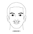
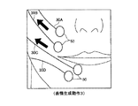
図5A〜図5Dは顔面表情の代表的な動作(表情)1〜4を模式式的に示す図である。図5A中矢印で示されるように、小頬骨筋103による顔面動作は、上口唇を斜め上方に上げる動作(表情)1が行える。すなわち、装着型人支援装置10の線状伝達部材30Aを駆動することで上口唇を斜め上方に上げる動作(表情)が可能になり、あたかも小頬骨筋103を動作させた場合と同じ表情を再現できる。
5A to 5D are diagrams schematically showing typical operations (facial expressions) 1 to 4 of facial expressions. As shown by an arrow in FIG. 5A, the facial movement by the small zygomatic muscle 103 can be an action (expression) 1 of raising the upper lip obliquely upward. That is, by driving the
図5B中矢印で示されるように、大頬骨筋104による顔面動作は、口角を斜め上方に上げる動作(表情)が行える。すなわち、装着型人支援装置10の線状伝達部材30Bを駆動することで口角を斜め上方に上げる動作(表情)2が可能になり、あたかも大頬骨筋104を動作させた場合と同じ表情を再現できる。
As shown by an arrow in FIG. 5B, the facial movement by the greater zygomatic muscle 104 can be an action (expression) of raising the mouth angle obliquely upward. That is, by driving the
図5C中矢印で示されるように、頬筋105による顔面動作は、口角を左右方向に広げる動作(表情)が行える。すなわち、装着型人支援装置10の線状伝達部材30B、30Cを駆動することで口角を左右方向に広げる動作(表情)3が可能になり、あたかも頬筋105を動作させた場合と同じ表情を再現できる。
As indicated by an arrow in FIG. 5C, the facial movement by the cheek muscle 105 can perform an action (expression) that widens the mouth angle in the left-right direction. That is, by driving the
図5D中矢印で示されるように、笑筋106による顔面動作は、口角の上部、下部を左右方向に広げる動作(表情)が行える。すなわち、装着型人支援装置10の線状伝達部材30C、30Dを駆動することで口角を左右方向に広げる動作(表情)4が可能になり、あたかも笑筋106を動作させた場合と同じ表情を再現できる。
As indicated by the arrows in FIG. 5D, the facial action by the smiley muscle 106 can be an action (expression) that widens the upper and lower corners of the mouth corner in the left-right direction. That is, by driving the
このような顔面表情の各動作は、駆動部40A〜40Dによる線状伝達部材30A〜30Dの変位量を調整及び組み合わせることで可能になる。また、上記記憶部72は、各神経伝達信号の検出量と各線状伝達部材30A〜30Dの変位量との組み合わせによる顔面表情がデータベースに格納されている。そのため、中央処理装置74は、生体信号検出センサ60A,60Bに検出信号(生体電位)に応じた各線状伝達部材30A〜30Dの変位量及びを演算して駆動部40A〜40Dへの駆動制御信号を演算する。
Each operation of such facial expressions can be performed by adjusting and combining the displacement amounts of the
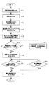
ここで、中央処理装置74が実行する演算処理の手順について図6のフローチャートを参照して説明する。図6のS11において、中央処理装置74は、生体信号検出センサ60A,60Bによって検出された神経伝達信号を読み込む。次のS12では、生体信号検出センサ60A,60Bによって検出された神経伝達信号に基づいて被装着者20が顔面表情をどのように動作させようとしているのかを特定する。本実施例では、記憶部72に格納されたデータベースから神経伝達信号に応じた顔面表情を選択する。例えば、図5A〜図5Dに示すような各顔面表情の中から当該神経伝達信号に応じた顔面表情を選択する。尚、記憶部72には、予め図5A〜図5Dに示すような各顔面表情だけでなく、その他の顔面表情のデータも格納されており、当該被装着者20の性格(例えば、いつも笑う、あまり笑わない、時々笑う、いつも怒る、あまり怒らない、時々怒る等)に合わせて顔面表情の選択条件(パラメータ)を予め設定することができるようにしてある。
Here, the procedure of the arithmetic processing executed by the
続いて、S13では、上記特定された顔面表情を作成するのに動作する表情筋の種別をデータベースから選択する。(例えば、図5Aに示す上口唇を斜め上方に上げる表情の場合には、小頬骨筋103を選択する。)
次のS14では、上記特定された顔面表情を作成する表情筋に対応する各線状伝達部材30A〜30Bの変位量を演算またはデータベースより得る。続いて、S15に進み、各線状伝達部材30A〜30Bの変位量に対応する駆動時間(顔面表情動作の持続可能時間、例えば、1秒〜2秒)及び、温度調整部44A〜44Dによる形状記憶合金42A〜42Dに対する温度制御値(目標値)を演算する。尚、顔面表情を大きく動作させる場合(例えば、大笑いする場合)には、駆動時間が長く設定され、温度制御値も大きい値に設定される。また、顔面表情を小さく動作させる場合(例えば、小さく微笑む場合)には、駆動時間が短く設定され、温度制御値も小さい値に設定される。また、上記駆動時間と温度制御値との組み合わせを変化させることでそのときの感情に応じた様々な表情を再現することが可能になる。
Subsequently, in S13, the type of facial expression muscle that operates to create the specified facial expression is selected from the database. (For example, in the case of the expression of raising the upper lip obliquely upward shown in FIG. 5A, the small zygomatic muscle 103 is selected.)
In the next S14, the displacement amount of each of the
次のS16では、各線状伝達部材30A〜30Bの駆動時間、温度制御値が予め設定された許容値以下か否かを判定する。S16において、各線状伝達部材30A〜30Bの駆動時間、温度制御値が予め設定された許容値以上のときは(NOの場合)、顔面表情筋に無理な力が作用するおそれがあるので、S17に進み、各線状伝達部材30A〜30Bのうち駆動時間Tが予め設定された許容値以上となった線状伝達部材の駆動時間を所定割合(例えば、5%)短縮する。そして、再度、S16に戻り、S17で修正した駆動時間、温度制御値が予め設定された許容値以下か否かを判定する。
In next S16, it is determined whether or not the drive time and temperature control value of each of the
S16において、各線状伝達部材30A〜30Bの駆動時間、温度制御値が全て予め設定された許容値未満のときは(YESの場合)、S18に進み、駆動制御信号出力部76A〜76Dを介して駆動部40A〜40Dの温度調整部44A〜44Dに駆動制御信号を出力する。これにより、温度調整部44A〜44Dは、形状記憶合金42A〜42Dを冷却または加熱して形状記憶合金42A〜42Dの温度を調整して形状記憶合金42A〜42Dの伸縮動作に伴う駆動力を発生させる。この形状記憶合金42A〜42Dによる駆動力は、各線状伝達部材30A〜30Bに伝達され、各線状伝達部材30A〜30Bが貼着された顔面の皮膚の各部分(被駆動部分)に対して引張り力または押圧力を作用させる。そのため、被装着者20の顔面表情は、顔面麻痺となった顔面右半分の皮膚が各線状伝達部材30A〜30Bによって駆動され、顔面右半分にも正常に動作する顔面差半分と同様な表情を再現することができる。
In S16, when the drive time and temperature control value of each of the
次のS19では、各線状伝達部材30A〜30Bの駆動経過時間がS15で演算された駆動時間に達したか否かをチェックする。S19において、各線状伝達部材30A〜30Bの駆動経過時間が駆動目標時間に達しないとき(NOの場合)、S20に進み、温度調整部44A〜44Dによる調整温度が温度制御値に達したか否かをチェックする。S20において、温度調整部44A〜44Dによる調整温度が温度制御値に達しないときは(NOの場合)、上記S19に戻り、S19,S20の処理を繰り返す。
In next S19, it is checked whether or not the driving elapsed time of each of the
S19において、各線状伝達部材30A〜30Bの駆動経過時間が駆動目標時間に達したとき(YESの場合)、あるいはS20において、温度調整部44A〜44Dによる調整温度が温度制御値に達したときは(YESの場合)、S21に進み、温度調整部44A〜44Dへの駆動制御信号の出力を停止する。この後は、再びS11に戻り、S11〜S21の制御処理を繰り返す。
When the elapsed driving time of each of the
このように、装着型人支援装置10は、各線状伝達部材30A〜30Dを被装着者20の皮膚に貼着させ、当該被装着者20の意思に応じて駆動制御信号を生成し、この駆動制御信号に基づいて駆動部40による駆動力を制御して各線状伝達部材30A〜30Dを駆動するため、当該被装着者20の意思に合った駆動力を被装着者20の表情筋に対応する被駆動部分に伝達して当該装着者20の麻痺した動作(表情)を正確に補助することが可能になる。
As described above, the wearable
すなわち、被装着者が顔面表情麻痺の場合には、顔の表情筋を覆う皮膚に各線状伝達部材30A〜30Bの一端を貼着させて顔の表情を被装着者の意思に応じて表現することが可能になり、被装着者20の感情や意思に合った顔表情の作成を補助することができる。そのため、顔面表情麻痺、あるいは高次脳機能障害の人の機能回復訓練(リハビリテーション)を支援することも可能になる。
That is, when the wearer has facial expression paralysis, one end of each of the
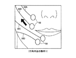
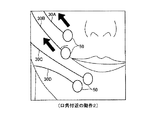
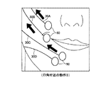
図7A〜図7Cは口角付近の動作1〜3を模式的に示す図である。図7Aに示されるように、線状伝達部材30Cを介して駆動部40Cの引張り力を口角付近に伝達した場合、被装着者20の口角を側方に広げる動作1(微笑動作)が行える。図7Bに示されるように、線状伝達部材30A,30Bを介して駆動部40A,40Bの引張り力を口角付近に伝達した場合、被装着者20の口角を側方及び斜め上方に広げる動作(小さく笑う動作)2が行える。図7Cに示されるように、線状伝達部材30A〜30Cを介して駆動部40A〜40Cの引張り力を口角付近に伝達した場合、被装着者20の口角及び頬を側方及び斜め上方に広げる動作(中程度に笑う動作)3が行える。
7A to 7C are diagrams schematically showing the operations 1 to 3 near the mouth corner. As shown in FIG. 7A, when the tensile force of the
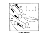
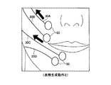
図8A〜図8Cは表情生成動作1〜3を模式的に示す図である。図8Aに示されるように、線状伝達部材30A〜30Dを介して駆動部40A〜40Dの引張り力を口角の上側及び下側に伝達した場合、被装着者20の表情は穏やかな表情動作1となる。図8Bに示されるように、線状伝達部材30A,30Cを介して駆動部40A,40Cの引張り力を頬及び口角の下側に伝達した場合、被装着者20の表情は頬及び口角を側方に広げる表情動作2となる。図8Cに示されるように、線状伝達部材30B,30Cの引張り力を口角の上側、下側に伝達した場合、被装着者20の表情は口角及び頬を斜め上方に持ち上げる表情動作3が行える。
8A to 8C are diagrams schematically illustrating facial expression generation operations 1 to 3. As shown in FIG. 8A, when the tensile force of the
ここで、変形例について説明する。 Here, a modified example will be described.
図9は変形例1を示すシステム構成図である。図9において、前述した図2と同一部分には同一符号を付してその説明を省略する。 FIG. 9 is a system configuration diagram showing a first modification. In FIG. 9, the same parts as those in FIG.
図9に示されるように、変形例1では、指令信号生成手段60が手動操作式のコントローラ200により構成されている。このコントローラ200としては、棒状の操作部210を傾斜させる方向に応じた操作信号を出力するジョイスティック型のコントローラが用いられる。
As shown in FIG. 9, in the first modification, the command signal generating means 60 is configured by a manually operated
被装着者20は、そのときの感情に応じてコントローラ200上に起立した操作部210を周方向(360度)の何れかの方向に傾けることで、任意の操作信号を中央処理装置74に出力することができる。操作部210の付け根部分の周囲には、例えば、大笑い、中笑い、微笑、小笑といった文字が表示されており、この表示を目安にして操作することができる。また、コントローラ200は、操作部210が操作されない場合には、中立位置であるので、操作信号を出力しない。
The
中央処理装置74では、前述した図6のS11で生体信号検出センサ60A,60Bの検出信号(生体電位)を読み込む代わりにコントローラ200からの操作信号を読み込むことで、前述した実施例の場合と同様に被装着者20の意思に応じた顔の表情を作成することが可能になる。従って、上記生体信号検出センサ60A,60Bが神経伝達信号を検出することが難しい場合には、コントローラ200を被装着者20自身が手動操作することで被装着者20の意思に応じた顔面表情を動作補助することが可能になる。
The
また、コントローラ200としては、ジョイスティック型のもの限らず、例えば、各線状伝達部材30A〜30D毎のスライドスイッチを並設したコントロールパネルにより、各線状伝達部材30A〜30Dに対応する操作信号を個別に生成することも可能である。
Further, the
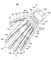
図10は変形例2の装着状態を示す斜視図である。図10において、前述した図2と同一部分には同一符号を付してその説明を省略する。 FIG. 10 is a perspective view showing a mounting state of the second modification. 10, the same parts as those in FIG. 2 described above are denoted by the same reference numerals, and the description thereof is omitted.
図10に示されるように、変形例2では、手のひらに装着型人支援装置300を装着する構成であり、被装着者の動作支援、動作教示及び機能回復訓練を行なうものである。
As shown in FIG. 10, in the second modification, the wearable
装着型人支援装置300は、各指(被駆動部分)に沿うように配された線状伝達部材30A〜30Eと、線状伝達部材30A〜30Eの他端に結合され、被駆動部分から離間した他の部分に装着される駆動部40A〜40Eと、線状伝達部材30A〜30Eを被装着者20の各指の皮膚に貼着させる貼着部材50と、当該被装着者20の意思に応じた駆動制御信号を生成する生体信号検出センサ60A,60Bと、生体信号検出センサ60A,60Bから出力された指令信号に基づいて駆動部40A〜40Eによる駆動力を制御する制御ユニット70とから構成されている。
The wearable
制御ユニット70は、被装着者20の手首に装着されたリストバンド310に保持されている。駆動部40A〜40Eは、夫々形状記憶合金42A〜42Eと、形状記憶合金の温度を調整する温度調整部44A〜44Eとからなる。
The
生体信号検出センサ60A,60Bは、被装着者20の手首と肘との間に配された腕の皮膚に貼着されている。すなわち、生体信号検出センサ60A,60Bは、脳から腕の筋肉に送出された神経伝達信号を生体信号として検出する位置に配されている。従って、被装着者20が指を動作させようと思考した場合、生体信号検出センサ60A,60Bは、脳から腕に伝達された指を動作させる神経伝達信号(生体電位)を検出し、制御ユニット70に指を動作させる神経伝達信号を出力する。
The biological
このように、装着型人支援装置300は、各線状伝達部材30A〜30Dを被装着者20の皮膚に貼着させ、当該被装着者20の意思に応じて駆動制御信号を生成し、この駆動制御信号に基づいて駆動部40A〜40Eによる駆動力を制御して各線状伝達部材30A〜30Eを駆動するため、当該被装着者20の意思に合った駆動力を被装着者20の各指に伝達して当該装着者20の麻痺した指の動作を正確に補助することが可能になる。
As described above, the wearable
そのため、手の各指の神経系統が麻痺している場合でも、装着型人支援装置300を手に装着することで機能回復動作を効率良く補助することが可能になる。
Therefore, even when the nervous system of each finger of the hand is paralyzed, the function recovery operation can be efficiently assisted by mounting the wearable
上記実施例では、顔の表情筋の動作や手の指の動作を補助、あるいは機能回復訓練を行なう場合を例に挙げて説明したが、これに限らず、これ以外の身体の動作を補助する装置にも本発明を適用できるのは勿論である。 In the above embodiment, the case of assisting facial facial muscles and finger movements or performing function recovery training has been described as an example. However, the present invention is not limited to this, and other body movements are assisted. Of course, the present invention can also be applied to an apparatus.
上記実施例において、被装着者20の顔面右半分が顔面麻痺となった場合を例に挙げて説明したが、顔面差半分が顔面麻痺となった場合にも本発明を適用することが可能であり、あるいは顔面全体が麻痺している場合でも各線状伝達部材30A〜30Bを顔面の左側
及び右側に配することで、顔面全体が動作するように補助することも可能である。この場合、生体信号検出センサ60A,60Bにより神経伝達信号を検出できないおそれがあるが、上記手動操作方式のコントローラ200を操作すれば顔全体の動作補助も可能である。
In the above embodiment, the case where the right half of the face of the
10,300 装着型人支援装置
20 被装着者
30A〜30D 線状伝達部材
32A〜32D 保護チューブ
40A〜40D 駆動部
42A〜42D 形状記憶合金
44A〜44D 温度調整部
50 貼着部材
60 指令信号生成手段
60A,60B 生体信号検出センサ
70 制御ユニット
72 記憶手段
74 中央処理装置
76A〜76D 駆動制御信号出力部
80 フレーム
90 バッテリ
103 小頬骨筋
104 大頬骨筋
106 笑筋
107 咬筋
109 下唇下制筋
120A,120B 顔面神経信号検出領域
200 コントローラ
DESCRIPTION OF SYMBOLS 10,300 Wearable
Claims (6)
該線状伝達部材の他端に結合され、前記被駆動部分から離間した他の部分に装着される駆動部と、
前記線状伝達部材を前記被装着者の皮膚に貼着させる貼着部材と、
当該被装着者の意思に応じた指令信号を生成する指令信号生成手段と、
該指令信号生成手段から出力された指令信号に基づいて前記駆動部による駆動力を制御する制御部と、
を備え、
前記駆動部は、駆動力を発生させる際に駆動音を生じない無音方式のアクチュエータであることを特徴とする装着型人支援装置。 A linear transmission member whose one end is attached to a driven region of the wearer's skin;
A drive unit coupled to the other end of the linear transmission member and attached to another part spaced from the driven part;
An adhesive member for attaching the linear transmission member to the skin of the wearer; and
Command signal generating means for generating a command signal according to the intention of the wearer;
A control unit for controlling the driving force by the driving unit based on the command signal output from the command signal generating means;
Bei to give a,
The wearable person support apparatus , wherein the driving unit is a silent actuator that does not generate a driving sound when generating a driving force .
前記線状伝達部材は、断面が微細かつ扁平形状に形成されることを特徴とする装着型人支援装置。 The wearable person support device according to claim 1 ,
The wearable person support device, wherein the linear transmission member has a fine cross section and a flat shape.
前記駆動部は、
前記線状伝達部材に連結され、温度に応じた形状に変位する形状記憶合金と、
前記形状記憶合金の温度を調整する温度調整手段と、
からなることを特徴とする装着型人支援装置。 The wearable person support device according to claim 1 or 2 ,
The drive unit is
A shape memory alloy connected to the linear transmission member and displaced into a shape according to temperature;
Temperature adjusting means for adjusting the temperature of the shape memory alloy;
A wearable human support device comprising:
前記線状伝達部材の一端を前記被装着者の顔の表情筋を覆う皮膚に貼着し、
前記駆動部及び前記制御部を前記被装着者の後頭部に配したことを特徴とする装着型人支援装置。 The wearable person support device according to any one of claims 1 to 3 ,
Adhering one end of the linear transmission member to the skin covering the facial expression muscle of the wearer,
The wearable person support apparatus, wherein the drive unit and the control unit are arranged on the back head of the wearer.
前記指令信号生成手段は、前記被装着者の筋肉を動作させるための生体信号を検出する生体信号検出手段であり、
前記制御部は、前記生体信号検出手段により検出された生体信号に基づき前記被装着者が行なうとする顔の表情に応じた駆動制御信号を生成し、当該駆動制御信号を前記駆動部に印加することを特徴とする装着型人支援装置。 The wearable person support device according to any one of claims 1 to 4 ,
The command signal generation means is a biological signal detection means for detecting a biological signal for operating the muscle of the wearer,
The control unit generates a drive control signal corresponding to a facial expression to be performed by the wearer based on the biological signal detected by the biological signal detection unit, and applies the drive control signal to the drive unit. A wearable human support device characterized by the above.
前記指令信号生成手段は、前記被装着者が操作するコントローラであり、
前記制御部は、前記コントローラからの指令信号に応じた駆動制御信号を生成し、当該駆動制御信号を前記駆動部に印加することを特徴とする装着型人支援装置。 The wearable person support device according to any one of claims 1 to 4 ,
The command signal generating means is a controller operated by the wearer,
The control unit generates a drive control signal according to a command signal from the controller, and applies the drive control signal to the drive unit.
Priority Applications (1)
| Application Number | Priority Date | Filing Date | Title |
|---|---|---|---|
| JP2008140502A JP5317536B2 (en) | 2008-05-29 | 2008-05-29 | Wearable human support device |
Applications Claiming Priority (1)
| Application Number | Priority Date | Filing Date | Title |
|---|---|---|---|
| JP2008140502A JP5317536B2 (en) | 2008-05-29 | 2008-05-29 | Wearable human support device |
Publications (2)
| Publication Number | Publication Date |
|---|---|
| JP2009285115A JP2009285115A (en) | 2009-12-10 |
| JP5317536B2 true JP5317536B2 (en) | 2013-10-16 |
Family
ID=41454907
Family Applications (1)
| Application Number | Title | Priority Date | Filing Date |
|---|---|---|---|
| JP2008140502A Active JP5317536B2 (en) | 2008-05-29 | 2008-05-29 | Wearable human support device |
Country Status (1)
| Country | Link |
|---|---|
| JP (1) | JP5317536B2 (en) |
Families Citing this family (3)
| Publication number | Priority date | Publication date | Assignee | Title |
|---|---|---|---|---|
| KR20210093281A (en) * | 2018-11-09 | 2021-07-27 | 아킬리 인터랙티브 랩스 인크. | Facial expression detection for the examination and treatment of emotional disorders |
| CN111449807B (en) * | 2020-03-25 | 2023-05-26 | 深圳市大族三维科技有限公司 | Method and device for judging applicability of nasal prosthesis, terminal equipment and storage medium |
| CN118178162A (en) * | 2024-04-12 | 2024-06-14 | 上海交通大学 | Facial paralysis rehabilitation training robot, system and method |
Family Cites Families (5)
| Publication number | Priority date | Publication date | Assignee | Title |
|---|---|---|---|---|
| JP3929509B2 (en) * | 1995-02-23 | 2007-06-13 | ソニー株式会社 | Information output device |
| US5865770A (en) * | 1995-12-06 | 1999-02-02 | Schectman; Leonard A. | Device to counteract paralysis |
| JP3978972B2 (en) * | 2000-03-28 | 2007-09-19 | セイコーエプソン株式会社 | Body-worn muscle strength assist device |
| JP4178187B2 (en) * | 2005-01-26 | 2008-11-12 | 国立大学法人 筑波大学 | Wearable motion assist device and control program |
| JP4997416B2 (en) * | 2006-03-22 | 2012-08-08 | 国立大学法人 筑波大学 | Rotation adjustment device and control method of the rotation device |
-
2008
- 2008-05-29 JP JP2008140502A patent/JP5317536B2/en active Active
Also Published As
| Publication number | Publication date |
|---|---|
| JP2009285115A (en) | 2009-12-10 |
Similar Documents
| Publication | Publication Date | Title |
|---|---|---|
| Jayatilake et al. | Robot assisted physiotherapy to support rehabilitation of facial paralysis | |
| Connelly et al. | A pneumatic glove and immersive virtual reality environment for hand rehabilitative training after stroke | |
| Shull et al. | Haptic wearables as sensory replacement, sensory augmentation and trainer–a review | |
| Knaepen et al. | Human–robot interaction: Kinematics and muscle activity inside a powered compliant knee exoskeleton | |
| US9498623B2 (en) | Rehabilitation system | |
| US9387112B2 (en) | Myoelectric hand orthosis | |
| CN108290037B (en) | Electrode positioning system and method | |
| JPH09507764A (en) | Image recognizer for the blind and the visually impaired | |
| Pioggia et al. | Exploring emotional and imitational android-based interactions in autistic spectrum disorders | |
| JP5317536B2 (en) | Wearable human support device | |
| JP2004329490A (en) | Finger motor function recovery support tool and finger motor function recovery support system | |
| Ishiguro | Android science | |
| Lontis et al. | Wheelchair control with inductive intra-oral tongue interface for individuals with tetraplegia | |
| CN113616923A (en) | Biofeedback electrostimulation and mirror image combined hand function rehabilitation device | |
| Kiguchi et al. | Neuro-fuzzy based motion control of a robotic exoskeleton: considering end-effector force vectors | |
| Decker et al. | A hand exoskeleton device for robot assisted sensory-motor training after stroke | |
| KR102386359B1 (en) | System and method for controlling exoskeleton robot using brain waves according to motion imagination | |
| CN213607940U (en) | A rehabilitation system for hand dysfunction | |
| JP4608656B2 (en) | Limb function recovery support device | |
| JP7693184B2 (en) | Rehabilitation support device and rehabilitation support method | |
| Ong et al. | Recent developments of robotic exoskeletons for hand rehabilitation | |
| JP2004254876A (en) | Motor function assisting device and method | |
| Jayatilake et al. | A wearable robot mask to support rehabilitation of facial paralysis | |
| CN118253008A (en) | Rehabilitation method, system and equipment of environment-rich combined rehabilitation robot | |
| JP7531813B2 (en) | Rehabilitation support system, program and control device |
Legal Events
| Date | Code | Title | Description |
|---|---|---|---|
| A621 | Written request for application examination |
Free format text: JAPANESE INTERMEDIATE CODE: A621 Effective date: 20110530 |
|
| A521 | Request for written amendment filed |
Free format text: JAPANESE INTERMEDIATE CODE: A523 Effective date: 20110701 |
|
| A131 | Notification of reasons for refusal |
Free format text: JAPANESE INTERMEDIATE CODE: A131 Effective date: 20130108 |
|
| A711 | Notification of change in applicant |
Free format text: JAPANESE INTERMEDIATE CODE: A711 Effective date: 20130304 |
|
| A521 | Request for written amendment filed |
Free format text: JAPANESE INTERMEDIATE CODE: A523 Effective date: 20130311 |
|
| A521 | Request for written amendment filed |
Free format text: JAPANESE INTERMEDIATE CODE: A821 Effective date: 20130304 |
|
| TRDD | Decision of grant or rejection written | ||
| A01 | Written decision to grant a patent or to grant a registration (utility model) |
Free format text: JAPANESE INTERMEDIATE CODE: A01 Effective date: 20130625 |
|
| A61 | First payment of annual fees (during grant procedure) |
Free format text: JAPANESE INTERMEDIATE CODE: A61 Effective date: 20130709 |
|
| R150 | Certificate of patent or registration of utility model |
Ref document number: 5317536 Country of ref document: JP Free format text: JAPANESE INTERMEDIATE CODE: R150 Free format text: JAPANESE INTERMEDIATE CODE: R150 |
|
| R250 | Receipt of annual fees |
Free format text: JAPANESE INTERMEDIATE CODE: R250 |
|
| R250 | Receipt of annual fees |
Free format text: JAPANESE INTERMEDIATE CODE: R250 |
|
| R250 | Receipt of annual fees |
Free format text: JAPANESE INTERMEDIATE CODE: R250 |
|
| R250 | Receipt of annual fees |
Free format text: JAPANESE INTERMEDIATE CODE: R250 |
|
| R250 | Receipt of annual fees |
Free format text: JAPANESE INTERMEDIATE CODE: R250 |