JP5312729B2 - Display system - Google Patents
Display system Download PDFInfo
- Publication number
- JP5312729B2 JP5312729B2 JP2006227202A JP2006227202A JP5312729B2 JP 5312729 B2 JP5312729 B2 JP 5312729B2 JP 2006227202 A JP2006227202 A JP 2006227202A JP 2006227202 A JP2006227202 A JP 2006227202A JP 5312729 B2 JP5312729 B2 JP 5312729B2
- Authority
- JP
- Japan
- Prior art keywords
- display device
- remote controller
- display
- common voltage
- liquid crystal
- Prior art date
- Legal status (The legal status is an assumption and is not a legal conclusion. Google has not performed a legal analysis and makes no representation as to the accuracy of the status listed.)
- Active
Links
Images


Classifications
-
- G—PHYSICS
- G09—EDUCATION; CRYPTOGRAPHY; DISPLAY; ADVERTISING; SEALS
- G09G—ARRANGEMENTS OR CIRCUITS FOR CONTROL OF INDICATING DEVICES USING STATIC MEANS TO PRESENT VARIABLE INFORMATION
- G09G3/00—Control arrangements or circuits, of interest only in connection with visual indicators other than cathode-ray tubes
- G09G3/20—Control arrangements or circuits, of interest only in connection with visual indicators other than cathode-ray tubes for presentation of an assembly of a number of characters, e.g. a page, by composing the assembly by combination of individual elements arranged in a matrix no fixed position being assigned to or needed to be assigned to the individual characters or partial characters
-
- G—PHYSICS
- G09—EDUCATION; CRYPTOGRAPHY; DISPLAY; ADVERTISING; SEALS
- G09F—DISPLAYING; ADVERTISING; SIGNS; LABELS OR NAME-PLATES; SEALS
- G09F27/00—Combined visual and audible advertising or displaying, e.g. for public address
-
- G—PHYSICS
- G09—EDUCATION; CRYPTOGRAPHY; DISPLAY; ADVERTISING; SEALS
- G09F—DISPLAYING; ADVERTISING; SIGNS; LABELS OR NAME-PLATES; SEALS
- G09F9/00—Indicating arrangements for variable information in which the information is built-up on a support by selection or combination of individual elements
- G09F9/30—Indicating arrangements for variable information in which the information is built-up on a support by selection or combination of individual elements in which the desired character or characters are formed by combining individual elements
- G09F9/35—Indicating arrangements for variable information in which the information is built-up on a support by selection or combination of individual elements in which the desired character or characters are formed by combining individual elements being liquid crystals
-
- G—PHYSICS
- G09—EDUCATION; CRYPTOGRAPHY; DISPLAY; ADVERTISING; SEALS
- G09G—ARRANGEMENTS OR CIRCUITS FOR CONTROL OF INDICATING DEVICES USING STATIC MEANS TO PRESENT VARIABLE INFORMATION
- G09G2320/00—Control of display operating conditions
- G09G2320/02—Improving the quality of display appearance
- G09G2320/0247—Flicker reduction other than flicker reduction circuits used for single beam cathode-ray tubes
-
- G—PHYSICS
- G09—EDUCATION; CRYPTOGRAPHY; DISPLAY; ADVERTISING; SEALS
- G09G—ARRANGEMENTS OR CIRCUITS FOR CONTROL OF INDICATING DEVICES USING STATIC MEANS TO PRESENT VARIABLE INFORMATION
- G09G2320/00—Control of display operating conditions
- G09G2320/04—Maintaining the quality of display appearance
- G09G2320/041—Temperature compensation
-
- G—PHYSICS
- G09—EDUCATION; CRYPTOGRAPHY; DISPLAY; ADVERTISING; SEALS
- G09G—ARRANGEMENTS OR CIRCUITS FOR CONTROL OF INDICATING DEVICES USING STATIC MEANS TO PRESENT VARIABLE INFORMATION
- G09G2320/00—Control of display operating conditions
- G09G2320/06—Adjustment of display parameters
- G09G2320/0606—Manual adjustment
-
- G—PHYSICS
- G09—EDUCATION; CRYPTOGRAPHY; DISPLAY; ADVERTISING; SEALS
- G09G—ARRANGEMENTS OR CIRCUITS FOR CONTROL OF INDICATING DEVICES USING STATIC MEANS TO PRESENT VARIABLE INFORMATION
- G09G2320/00—Control of display operating conditions
- G09G2320/06—Adjustment of display parameters
- G09G2320/0626—Adjustment of display parameters for control of overall brightness
-
- G—PHYSICS
- G09—EDUCATION; CRYPTOGRAPHY; DISPLAY; ADVERTISING; SEALS
- G09G—ARRANGEMENTS OR CIRCUITS FOR CONTROL OF INDICATING DEVICES USING STATIC MEANS TO PRESENT VARIABLE INFORMATION
- G09G2370/00—Aspects of data communication
- G09G2370/04—Exchange of auxiliary data, i.e. other than image data, between monitor and graphics controller
-
- G—PHYSICS
- G09—EDUCATION; CRYPTOGRAPHY; DISPLAY; ADVERTISING; SEALS
- G09G—ARRANGEMENTS OR CIRCUITS FOR CONTROL OF INDICATING DEVICES USING STATIC MEANS TO PRESENT VARIABLE INFORMATION
- G09G3/00—Control arrangements or circuits, of interest only in connection with visual indicators other than cathode-ray tubes
- G09G3/20—Control arrangements or circuits, of interest only in connection with visual indicators other than cathode-ray tubes for presentation of an assembly of a number of characters, e.g. a page, by composing the assembly by combination of individual elements arranged in a matrix no fixed position being assigned to or needed to be assigned to the individual characters or partial characters
- G09G3/22—Control arrangements or circuits, of interest only in connection with visual indicators other than cathode-ray tubes for presentation of an assembly of a number of characters, e.g. a page, by composing the assembly by combination of individual elements arranged in a matrix no fixed position being assigned to or needed to be assigned to the individual characters or partial characters using controlled light sources
- G09G3/30—Control arrangements or circuits, of interest only in connection with visual indicators other than cathode-ray tubes for presentation of an assembly of a number of characters, e.g. a page, by composing the assembly by combination of individual elements arranged in a matrix no fixed position being assigned to or needed to be assigned to the individual characters or partial characters using controlled light sources using electroluminescent panels
- G09G3/32—Control arrangements or circuits, of interest only in connection with visual indicators other than cathode-ray tubes for presentation of an assembly of a number of characters, e.g. a page, by composing the assembly by combination of individual elements arranged in a matrix no fixed position being assigned to or needed to be assigned to the individual characters or partial characters using controlled light sources using electroluminescent panels semiconductive, e.g. using light-emitting diodes [LED]
- G09G3/3208—Control arrangements or circuits, of interest only in connection with visual indicators other than cathode-ray tubes for presentation of an assembly of a number of characters, e.g. a page, by composing the assembly by combination of individual elements arranged in a matrix no fixed position being assigned to or needed to be assigned to the individual characters or partial characters using controlled light sources using electroluminescent panels semiconductive, e.g. using light-emitting diodes [LED] organic, e.g. using organic light-emitting diodes [OLED]
-
- G—PHYSICS
- G09—EDUCATION; CRYPTOGRAPHY; DISPLAY; ADVERTISING; SEALS
- G09G—ARRANGEMENTS OR CIRCUITS FOR CONTROL OF INDICATING DEVICES USING STATIC MEANS TO PRESENT VARIABLE INFORMATION
- G09G3/00—Control arrangements or circuits, of interest only in connection with visual indicators other than cathode-ray tubes
- G09G3/20—Control arrangements or circuits, of interest only in connection with visual indicators other than cathode-ray tubes for presentation of an assembly of a number of characters, e.g. a page, by composing the assembly by combination of individual elements arranged in a matrix no fixed position being assigned to or needed to be assigned to the individual characters or partial characters
- G09G3/34—Control arrangements or circuits, of interest only in connection with visual indicators other than cathode-ray tubes for presentation of an assembly of a number of characters, e.g. a page, by composing the assembly by combination of individual elements arranged in a matrix no fixed position being assigned to or needed to be assigned to the individual characters or partial characters by control of light from an independent source
- G09G3/36—Control arrangements or circuits, of interest only in connection with visual indicators other than cathode-ray tubes for presentation of an assembly of a number of characters, e.g. a page, by composing the assembly by combination of individual elements arranged in a matrix no fixed position being assigned to or needed to be assigned to the individual characters or partial characters by control of light from an independent source using liquid crystals
- G09G3/3611—Control of matrices with row and column drivers
- G09G3/3648—Control of matrices with row and column drivers using an active matrix
Description
本発明はディスプレイシステムに係り、より具体的には公衆情報ディスプレイ(public information display:PID)システムに関する。 The present invention relates to a display system, and more particularly to a public information display (PID) system.
空港、汽車駅の待合室、競技場、公演場及び病院などの公共場所に情報表示のための公衆情報ディスプレイ装置を設けることは一般化されており、空間占有を最小化して、かつ低消費電力のために、公衆情報ディスプレイ装置には平板ディスプレイ装置が多用されている。平板ディスプレイ装置は映像表示パネルの種類に応じてOLED(Organic Light Emitting Diode)、LCD(Liquid Crystal Display)、FED(Field Emission Display)、VFD(Vacuum Fluorescent Display)、PDP(Plasma Display Panel)などがある。 Public information display devices for displaying information in public places such as airports, train station waiting rooms, stadiums, performance halls, and hospitals are common, minimizing space occupancy and reducing power consumption. Therefore, flat display devices are frequently used for public information display devices. Flat display devices include OLED (Organic Light Emitting Diode), LCD (Liquid Crystal Display), FED (Vacuum Fluorescent Display), VFD (Vacuum Fluorescent Display), and VFD (Vacuum Fluorescent Display) depending on the type of video display panel. .
一般的に、平板ディスプレイ装置は前面部にOSD(on screen display)調整ボタンを具備して、ユーザによって画面の明暗、明るさ、水平位置、垂直位置、輪郭補正などの特性が調整されるように構成される。 In general, a flat panel display device has an on-screen display (OSD) adjustment button on the front surface thereof so that the user can adjust characteristics such as screen brightness, brightness, horizontal position, vertical position, and contour correction. Composed.
一方、公衆情報ディスプレイ装置として用いられる平板ディスプレイ装置は天井にぶら下げられるように配置されるか、壁面の高い所に付着して人々の通行に邪魔にならないように設けられる。このように高い所に設けられた平板ディスプレイ装置の特性を変更することは容易ではない。 On the other hand, a flat panel display device used as a public information display device is arranged so as to be hung from a ceiling or attached to a high wall surface so as not to obstruct people's traffic. It is not easy to change the characteristics of the flat display device provided at such a high place.
公衆情報ディスプレイ装置は、大衆に情報を知らせるための目的として使われるので、故障をあらかじめ防止しなければならない必要性が高く、残余の寿命に対する管理も必要である。このような故障防止及び残余寿命管理のためにはディスプレイ装置の特性情報をモニタリングしなければならないことがあった。 Since the public information display device is used for the purpose of informing the public of information, it is highly necessary to prevent failure in advance and management of the remaining life is also necessary. In order to prevent such a failure and manage the remaining life, it is sometimes necessary to monitor the characteristic information of the display device.
また、公衆情報ディスプレイ装置は長期間動作状態にあるので、共通電圧VCOMの変化によるフリッカー現象の発生率が高いが、ディスプレイ装置の共通電圧を調整することは困難であった。 In addition, since the public information display device has been in operation for a long time, the occurrence rate of flicker phenomenon due to the change of the common voltage VCOM is high, but it is difficult to adjust the common voltage of the display device.
本発明の目的は、ディスプレイ装置の特性情報を容易にモニタリング及び調整することができるディスプレイシステムを提供することにある。 An object of the present invention is to provide a display system capable of easily monitoring and adjusting characteristic information of a display device.
本発明の他の目的は、ディスプレイ装置の特性情報を容易にモニタリング及び調整することができるディスプレイシステムの動作方法を提供することにある。 Another object of the present invention is to provide a method of operating a display system that can easily monitor and adjust characteristic information of a display device.
本発明の他の目的は、ディスプレイ装置の特性情報を容易にモニタリング及び調整することができるリモートコントローラの動作方法を提供することにある。 Another object of the present invention is to provide a method of operating a remote controller that can easily monitor and adjust characteristic information of a display device.
本発明の他の目的は、リモートコントローラの制御に応答して特性情報をリモートコントローラに提供し、特性情報をリモートコントローラから受信された調整値に変更することができるディスプレイ装置の制御方法を提供することにある。 Another object of the present invention is to provide a display device control method capable of providing characteristic information to a remote controller in response to control of the remote controller and changing the characteristic information to an adjustment value received from the remote controller. There is.
上述した目的を解決するために本発明の特徴によれば、ディスプレイシステムはディスプレイ装置、及びリモートコントローラを含む。リモートコントローラは前記ディスプレイ装置と無線通信して前記装置情報を獲得し、獲得された装置情報を表示するためのディスプレイパネルを含む。 In order to solve the above-described object, according to a feature of the present invention, a display system includes a display device and a remote controller. The remote controller includes a display panel for wirelessly communicating with the display device to obtain the device information and displaying the obtained device information.
前記リモートコントローラは、複数のキーを含み、押されたキーに対応するコードを発生するキーパッドと、前記キーパッドからの前記コードに応答して前記ディスプレイ装置に送られる命令を生成し、前記ディスプレイ装置から獲得された前記装置情報を前記ディスプレイパネルに表示するマイクロコントローラと、前記マイクロコントローラの制御に応じて前記ディスプレイ装置と無線通信する送受信器とを含む。 The remote controller includes a plurality of keys, generates a code corresponding to a pressed key, and generates a command sent to the display device in response to the code from the keypad, A microcontroller for displaying the device information acquired from the device on the display panel; and a transceiver for wirelessly communicating with the display device in accordance with the control of the microcontroller.
また前記リモートコントローラは、前記獲得された装置情報を調整し、調整された装置情報を前記ディスプレイ装置に送ることができる。 The remote controller may adjust the acquired device information and send the adjusted device information to the display device.
前記ディスプレイ装置は、前記装置情報を含む駆動回路と、前記駆動回路とデジタルインターフェースを通じて接続され、前記リモートコントローラから受信された命令に応答して動作する通信回路とを含む。 The display device includes a drive circuit including the device information, and a communication circuit connected to the drive circuit through a digital interface and operating in response to a command received from the remote controller.
前記通信回路は、前記駆動回路と前記デジタルインターフェースを通じて接続され、前記リモートコントローラから受信された命令に応答して前記デジタルインターフェースを通じて前記駆動回路から前記装置情報を読み出し、前記リモートコントローラから受信された前記調整された装置情報を前記駆動回路に提供するプロセッサと、前記プロセッサの制御に応答して前記リモートコントローラと無線通信する送受信器とを含む。 The communication circuit is connected to the drive circuit through the digital interface, reads the device information from the drive circuit through the digital interface in response to a command received from the remote controller, and is received from the remote controller. A processor that provides adjusted device information to the drive circuit; and a transceiver that communicates wirelessly with the remote controller in response to control of the processor.
前記インターフェースはシリアルデジタルインターフェースであり、双方向性を有するI2C(Inter Integrated Circuit)インターフェースである。 The interface is a serial digital interface, and is a bidirectional I 2 C (Inter Integrated Circuit) interface.
前記リモートコントローラは、前記ディスプレイ装置のフリッカーの程度を感知するための光センサ及び周辺温度を感知するための温度センサをさらに含み、前記光センサは前記リモートコントローラの背面に構成されることがのぞましい。 Preferably, the remote controller further includes a light sensor for sensing the flicker level of the display device and a temperature sensor for sensing the ambient temperature, and the light sensor is configured on the back of the remote controller.
本発明の他の特徴に係るディスプレイ装置及び前記ディスプレイ装置と無線通信するリモートコントローラを含むディスプレイシステムの動作方法は、前記リモートコントローラから前記ディスプレイ装置に装置情報要求命令を送り、前記装置情報要求命令に応答して前記ディスプレイ装置から前記リモートコントローラに装置情報を送り、前記ディスプレイ装置から受信された前記装置情報を前記リモートコントローラのディスプレイパネルに表示する各段階とを含む。 According to another aspect of the present invention, an operation method of a display system including a display device and a remote controller wirelessly communicating with the display device sends a device information request command from the remote controller to the display device. In response, sending device information from the display device to the remote controller and displaying the device information received from the display device on a display panel of the remote controller.
前記ディスプレイシステムの動作方法は、前記リモートコントローラから前記ディスプレイ装置に前記装置情報を調整するための調整命令を送り、前記調整命令に応答して前記ディスプレイ装置の前記装置情報を調整する各段階をさらに含むことができる。 The operation method of the display system further includes the steps of sending an adjustment command for adjusting the device information from the remote controller to the display device, and adjusting the device information of the display device in response to the adjustment command. Can be included.
本発明の他の特徴に係るディスプレイ装置及び前記ディスプレイ装置と無線通信するリモートコントローラを含むディスプレイシステムにおける前記リモートコントローラの動作方法は、動作モードを選択し、選択された動作モードに対応する命令を前記ディスプレイ装置に送り、前記ディスプレイ装置から応答を受信し、受信された応答を前記リモートコントローラに具備されたディスプレイパネルに表示する各段階とを含む。 An operation method of the remote controller in a display system including a display device according to another aspect of the present invention and a remote controller wirelessly communicating with the display device selects an operation mode and sends a command corresponding to the selected operation mode to the command. Sending to the display device, receiving a response from the display device, and displaying the received response on a display panel included in the remote controller.
本発明の他の特徴に係るディスプレイ装置及び前記ディスプレイ装置と無線通信するリモートコントローラを含むディスプレイシステムにおける前記ディスプレイ装置の動作方法は、前記リモートコントローラから命令を受信し、前記受信命令に対応する制御を実行する各段階とを含む。 An operation method of the display device in a display system including a display device according to another aspect of the present invention and a remote controller wirelessly communicating with the display device receives a command from the remote controller and performs control corresponding to the received command. Each stage to be executed.
このようなディスプレイシステム及びその動作方法によれば、リモートコントローラを利用してディスプレイ装置の特性情報を容易にモニタリング及び調整することができる。 According to such a display system and its operation method, it is possible to easily monitor and adjust the characteristic information of the display device using a remote controller.
前記リモートコントローラは、複数のキーを含み、押されたキーに対応するコードを発生するキーパッドと、前記キーパッドからの前記コードに応答して前記ディスプレイ装置に送られる命令を生成し、前記ディスプレイ装置から獲得された前記装置情報を前記ディスプレイパネルに表示するマイクロコントローラと、前記マイクロコントローラの制御に応じて前記ディスプレイ装置と無線通信する送受信器とを含む。 The remote controller includes a plurality of keys, generates a code corresponding to a pressed key, and generates a command sent to the display device in response to the code from the keypad, A microcontroller for displaying the device information acquired from the device on the display panel; and a transceiver for wirelessly communicating with the display device in accordance with the control of the microcontroller.
この実施形態において、前記ネットワーク通信ユニットは、無線通信ネットワークを通じて第1ホストに前記装置情報を送る。 In this embodiment, the network communication unit sends the device information to the first host through a wireless communication network.
この実施形態において、前記ネットワーク通信ユニットは、有線通信ネットワークを通じて第2ホストに前記装置情報を送る。 In this embodiment, the network communication unit sends the device information to the second host through a wired communication network.
本発明の他の特徴によれば、ディスプレイシステムは、映像信号及び駆動信号を提供する映像処理装置と、装置情報とを含み、前記駆動信号に応答して前記映像信号を表示するディスプレイ装置と、前記ディスプレイ装置と無線通信して前記装置情報を獲得し、獲得された装置情報を表示するためのディスプレイパネルを含むリモートコントローラとを含む。 According to another aspect of the present invention, a display system includes a video processing device that provides a video signal and a driving signal, device information, and a display device that displays the video signal in response to the driving signal; A remote controller including a display panel for wirelessly communicating with the display device to obtain the device information and displaying the obtained device information.
前記ディスプレイ装置は、前記リモートコントローラと通信する送受信器と、通信ネットワークを通じて外部ホストと通信し、前記外部ホストから入力される制御信号を前記映像処理装置に提供するネットワーク通信ユニットとを含む。 The display device includes a transceiver that communicates with the remote controller, and a network communication unit that communicates with an external host through a communication network and provides a control signal input from the external host to the video processing device.
この実施形態において、前記リモートコントローラは、複数のキーを含み、押されたキーに対応するコードを発生するキーパッドと、前記キーパッドからの前記コードに応答して前記ディスプレイ装置に送られる命令を生成し、前記ディスプレイ装置から獲得された前記装置情報を前記ディスプレイパネルに表示するマイクロコントローラと、前記マイクロコントローラの制御に応じて前記ディスプレイ装置と無線通信する送受信器とを含む。 In this embodiment, the remote controller includes a plurality of keys and generates a code corresponding to the pressed key, and a command sent to the display device in response to the code from the keypad. A microcontroller that generates and displays the device information acquired from the display device on the display panel; and a transceiver that communicates wirelessly with the display device under the control of the microcontroller.
前記ネットワーク通信ユニットは、無線通信ネットワークを通じて第1ホストに前記装置情報を送る。 The network communication unit sends the device information to the first host through a wireless communication network.
前記ネットワーク通信ユニットは、有線通信ネットワークを通じて第2ホストに前記装置情報を送る。 The network communication unit sends the device information to the second host through a wired communication network.
本発明のディスプレイシステム及びその動作方法によれば、リモートコントローラを利用してディスプレイ装置の特性情報を容易にモニタリング及び調整することができる。 According to the display system and the operation method of the present invention, it is possible to easily monitor and adjust the characteristic information of the display device using a remote controller.
以下、本発明の好ましい実施形態を添付の図面を参照して詳細に説明する。 Hereinafter, preferred embodiments of the present invention will be described in detail with reference to the accompanying drawings.
図1は本発明の好ましい実施形態に係るディスプレイシステムの構成を示す図である。ディスプレイシステム100は液晶表示装置200と、リモートコントローラ300とを含む。液晶表示装置200はOLED、LCD、FED、VFD、及びPDPのうちのいずれか一つである。液晶表示装置200の前面部にはリモートコントローラ300との信号送受信のための送受信端子(またはアンテナ)201が具備される。液晶表示装置200とリモートコントローラ300との間に送受信される信号は例えば、RF(radio frequency)信号である。本発明の一実施形態において、図1に示した液晶表示装置200は公衆情報ディスプレイPID装置として使われることが可能である。
FIG. 1 is a diagram showing a configuration of a display system according to a preferred embodiment of the present invention. The
リモートコントローラ300は前面部に配置されたディスプレイパネル301及びキーパッド302を含む。リモートコントローラ300の一面には液晶表示装置200との信号送受信のための送受信端子(または図示しないアンテナ)が具備される。
The
リモートコントローラ300はキーパッド302に具備された多数のキーのうち押されたキーに対応するコードに応答して液晶表示装置200と無線通信して液晶表示装置200の装置情報を獲得し、獲得された装置情報をディスプレイパネル301に表示する。また、リモートコントローラ300は獲得された装置情報を調整し、調整された装置情報を液晶表示装置200に送る。
The
液晶表示装置200はリモートコントローラ300から受信された命令に応答して内部に記憶(貯蔵)された装置情報をリモートコントローラ300に提供するか、またはリモートコントローラ300によって調整された装置情報を内部に記憶する。
The liquid
このような構成を有する本発明のディスプレイシステム100によれば、ユーザは液晶表示装置200とRF通信が可能な距離範囲でリモートコントローラ300を利用して液晶表示装置200の装置情報をモニタリングするか、または装置情報を変更することができる。
According to the
図2は図1に示したディスプレイ装置の一例である液晶表示装置の内部構成を具体的に示すブロック図である。 FIG. 2 is a block diagram specifically showing an internal configuration of a liquid crystal display device which is an example of the display device shown in FIG.
図2を参照すれば、本発明の一実施形態に係る液晶表示装置200は、液晶パネル210、ゲート駆動回路220、データ駆動回路230、通信回路240、制御回路250及び外部インターフェース260を含む。
Referring to FIG. 2, the liquid
液晶パネル110に互いに交差する複数のゲートラインGL1〜GLnと複数のデータラインDL1〜DLmが具備され、ゲートラインGL1〜GLnとデータラインDL1〜DLmによって定義された複数の画素領域には映像を表示する最小単位である複数の画素がそれぞれ具備される。画素のそれぞれは薄膜トランジスタTrと液晶キャパシタClcからなる。例えば、第1画素領域における薄膜トランジスタTrのゲート電極は第1ゲートラインGL1に接続され、ソース電極は第1データラインDL1に接続され、ドレイン電極は液晶キャパシタClcの一端に接続される。 The liquid crystal panel 110 includes a plurality of gate lines GL1 to GLn and a plurality of data lines DL1 to DLm, and an image is displayed on a plurality of pixel areas defined by the gate lines GL1 to GLn and the data lines DL1 to DLm. A plurality of pixels, which are the smallest units, are provided. Each pixel includes a thin film transistor Tr and a liquid crystal capacitor Clc. For example, the gate electrode of the thin film transistor Tr in the first pixel region is connected to the first gate line GL1, the source electrode is connected to the first data line DL1, and the drain electrode is connected to one end of the liquid crystal capacitor Clc.
ゲート駆動回路220はチップ形態からなり、複数のゲートラインGL1〜GLnに電気的に接続される。ゲート駆動回路220は第1同期信号SYNC1、第1及び第2クロック信号CKV、CKVB、第1及び第2駆動電圧VON、VOFFに応答してゲート信号を複数のゲートラインGL1〜GLnに順次に出力する。データ駆動回路230はチップ形態からなり、複数のデータラインDL1〜DLmに電気的に接続される。データ駆動回路230は第2同期信号SYNC2、アナログガンマ電圧VGMMA及び第3駆動電圧AVDDに応答してデータ信号を複数のデータラインDL1〜DLmに出力する。
The
一方、制御回路250は外部インターフェース260を通じて外部装置(図示しない)と接続される。外部インターフェース260は外部装置から提供された各種の信号を液晶表示装置200に適切な信号に変換した後、制御回路250に提供する。制御回路250はインバータコントローラ251、輝度センサ252、温度センサ253、ガンマ電圧発生回路254、タイミングコントローラ255、不揮発性メモリ256、共通電圧発生回路257、電源電圧発生回路258、及び内部インターフェース259を含む。
On the other hand, the
内部インターフェース259はデジタルシリアル(直列)インターフェースであり、制御回路250内のデバイス(インバータコントローラ251、輝度センサ252、温度センサ253、ガンマ電圧発生回路254、タイミングコントローラ255、不揮発性メモリ256、共通電圧発生回路257及び電源電圧発生回路258)は内部インターフェース259を通じて互いにデータ通信を実行する。
The
内部インターフェース259はデジタルシリアルインターフェースの一つであるI2C(Inter integrated circuit)インターフェースからなる。I2Cインターフェースは双方向性2−ワイヤインターフェースとして、データ通信のためのシリアルデータラインSDAと前記回路との間のデータ通信を制御及び同期化するためのシリアルクロックラインSCLからなる。I2Cインターフェースに接続された回路は固有のアドレスにより識別され、回路のそれぞれはデータを送信または受信することができる。回路の間でデータ伝達はマスタ―スレーブプロトコル方式で行われる。マスタはデータ伝送を開始し、かつクロック信号を生成し、マスタを除いた残りの回路はマスタとデータを取り交わすスレーブである。
The
本発明の一実施形態に係る制御回路250におけるマスタはタイミングコントローラ255であり、スレーブは不揮発性メモリ259、ガンマ電圧発生回路254、共通電圧発生回路257及び電源電圧発生回路258である。I2Cインターフェースはマルチマスタを有することができる。以下に説明する通信回路240内のプロセッサ242も内部インターフェース259のマスタとして動作する。
In the
図2では内部インターフェース259が2−ワイヤバスであるI2Cインターフェースからなることを示したが、内部インターフェース259は3−ワイヤバスであるシリアル周辺インターフェース(Serial Peripheral Interface;以下、SPIという)からなることもできる。図示しないが、SPIはデータ伝送のための第1シリアルデータライン、データ受信のための第2シリアルデータライン及びデバイスの間のデータ通信を制御及び同期化するためのシリアルクロックラインからなる。
Although FIG. 2 shows that the
インバータコントローラ251はバックライト(backlight、図示しない)に高電圧を供給するインバータ(図示しない)の動作を制御する。輝度センサ252は液晶パネル210にディスプレイされる映像の輝度を感知するためのセンサであり、温度センサ253は周辺温度感知センサである。温度センサ253はパネル210表面温度、制御回路250が実装された基板温度などを有するように設計されてもよい。
The
タイミングコントローラ255はチップ形態からなり、外部インターフェース260から映像データI−DATAと外部同期信号SYNC、MCLK、DEが入力される。タイミングコントローラ255は映像データI−DATAを1フレーム単位でフレームメモリ(図示しない)に記憶した後、1ライン単位で読み出してデータ駆動回路230に提供する。また、タイミングコントローラ255は外部同期信号SYNC、MCLK、DEを第1及び第2同期信号SYNC1、SYNC2、第1及び第2クロック信号CKV、CKVBに変換して出力する。
The
不揮発性メモリ256は例えば、EEPROMである。不揮発性メモリ256には内部インターフェース259を通じて入力された液晶パネル210に関する情報、例えば解像度とパネルサイズなどからなる初期データが記憶される。不揮発性メモリ256には液晶パネル210に表示された画面の平均輝度に応じて異なる階調値を有するガンマデータが記憶される。画面の平均輝度が基準輝度より高ければ、ガンマデータは基準ガンマより高い階調を有し、平均輝度が基準輝度より低ければ、ガンマデータは基準ガンマより低い階調を有する。
The
タイミングコントローラ255は不揮発性メモリ256に記憶されたデジタル形態のガンマデータを同期信号とともに内部インターフェース259を通じてガンマ電圧発生回路254に送る。ガンマ電圧発生回路254はタイミングコントローラ255からの同期信号に応答してガンマデータをアナログ形態のガンマ電圧VGMMAに変換する。ガンマ電圧発生回路254から出力されたガンマ電圧VGMMAはデータ駆動回路230に送られる。
The
タイミングコントローラ255は不揮発性メモリ256に記憶されたデータに基いて駆動電圧データを生成し、駆動電圧データと同期信号を内部インターフェース259を通じて電源電圧発生回路258に送る。電源電圧発生回路258は同期信号と駆動電圧データに応答して外部電圧Vpを液晶パネル210に適する第1乃至第3駆動電圧VON、VOFF、AVDD、ロジック電圧(図示しない)に変換して出力する。ここで、ロジック電圧は共通電圧発生回路257、タイミングコントローラ255及びガンマ電圧発生回路254を駆動させるための電圧である。
The
タイミングコントローラ255は不揮発性メモリ256に記憶されたデータに基いて共通電圧データを生成し、共通電圧データと同期信号を内部インターフェース259を通じて共通電圧発生回路257に送る。共通電圧発生回路257は共通電圧データと同期信号に応答して第3駆動電圧AVDDを液晶パネル210に適する共通電圧VCOMに変換して出力する。
The
通信回路240は送受信器241、プロセッサ242、及びメモリ243を含む。送受信器241は送受信端子(またはアンテナ、201)を通じてリモートコントローラ300から受信された無線信号をデジタル信号に変換してプロセッサ242に提供し、プロセッサ242からリモートコントローラ300に送られるデジタル信号を無線信号に変換して送受信端子201を通じてリモートコントローラ300に送る。
The
プロセッサ242は内部インターフェース259を通じて制御回路240内のデバイスと接続される。プロセッサ242はリモートコントローラ300から受信された命令に応答して液晶表示装置200の装置情報すなわち、制御回路240内のデバイス情報(例えば、輝度、温度、共通電圧、階調電圧など)または不揮発性メモリ256に記憶されたデータ(例えば、解像度、製造番号、累積使用時間、色相パラメータ、応答速度パラメータなど)をリモートコントローラ300に提供するか、または制御回路240内のデバイスの情報を変更する。メモリ243はプロセッサ242によって実行されるプロセスのプログラムを記憶する。
The
図3は図1に示した本発明の一実施形態に係るリモートコントローラ300の具体的な構成を示す図である。
FIG. 3 is a diagram showing a specific configuration of the
図3を参照すれば、リモートコントローラ300はディスプレイパネル301、キーパッド302、光センサ303、温度センサ304、マイクロコントローラ305、送受信器306、及び送受信端子307を含む。
Referring to FIG. 3, the
ディスプレイパネル301はLCD及びOLEDのうちのいずれか一つで構成され、マイクロコントローラ305の制御に応じてユーザによって選択される命令及び液晶装置200の装置情報を表示する。キーパッド302は複数のキーを含み、ユーザによって押されたキーに対応するコードをマイクロコントローラ305に提供する。ディスプレイパネル301がタッチスクリーンパネルに実現される場合、キーパッド302は不必要でありうる。タッチスクリーンパネルは押された座標に対応するコードをマイクロコントローラ305に提供する。光センサ303は液晶表示装置200の液晶パネル210の輝度感知のためのセンサである。温度センサ304は周辺温度を感知するためのセンサである。ユーザによってキーパッド302を通じて温度感知モードが選択されれば、マイクロコントローラ305は温度センサ304を動作させる。温度センサ304によって感知された温度はマイクロコントローラ305の制御に応じてディスプレイパネル301に表示される。ユーザはディスプレイパネル301に表示された周辺温度を考慮して液晶表示装置200の特性を調整することができる。
The
図3に示したリモートコントローラ300は光センサ303及び温度センサ304を含むが、液晶表示装置200の特性をモニタリング及び調整するために必要な多様なセンサを含んでもよい。
The
送受信器306は送受信端子307を通じて液晶表示装置200から伝送された無線信号をデジタル信号に変換してマイクロコントローラ305に提供し、マイクロコントローラ305から液晶表示装置200に伝送されるデジタル信号を無線信号に変換して送受信端子307を通じて液晶表示装置200に送る。
The
リモートコントローラ300はパワーオンされる時、ディスプレイパネル301に選択画面をディスプレイする。選択画面はユーザによって選択される動作モードを含む。動作モードは例えば、モニタリングモードと調整モードとを含む。モニタリングモードは累積使用時間表示モード、及び共通電圧VCOM/ガンマ電圧VGMMA表示モードを含み、調整モードはフリッカー受動調整モード及びフリッカー自動調整モードを含む。
The
累積使用時間は液晶表示装置200内の不揮発性メモリ256に記憶された情報として、液晶表示装置200が動作状態に置かれたすべて時間情報である。累積使用時間表示モードは不揮発性メモリ256に記憶された累積使用時間情報を表示するためのモードである。
The accumulated usage time is all time information when the liquid
共通電圧VCOM/ガンマ電圧VGMMA表示モードは共通電圧発生回路257の共通電圧VCOMデータ及びガンマ電圧発生回路254のガンマ電圧VGMMAデータを表示するためのモードである。この実施形態において、共通電圧発生回路257及びガンマ電圧発生回路254のそれぞれが共通電圧VCOMデータとガンマ電圧VGMMAデータを記憶するためのレジスタを具備し、プロセッサ242は共通電圧発生回路257及びガンマ電圧発生回路254から共通電圧VCOMデータとガンマ電圧VGMMAデータを読み出す。他の実施形態によるプロセッサ242は、共通電圧VCOM/ガンマ電圧VGMMA表示モードでタイミングコントローラ255から共通電圧VCOMデータとガンマ電圧VGMMAデータを読み出すように設計されてもよい。
The common voltage VCOM / gamma voltage VGMMA display mode is a mode for displaying the common voltage VCOM data of the common
フリッカー受動及び自動調整モードは共通電圧VCOM変化によるフリッカー発生を減少させるために共通電圧発生回路257の共通電圧VCOMデータを調整するモードである。
The flicker passive and automatic adjustment modes are modes in which the common voltage VCOM data of the common
リモートコントローラ300の動作モードには不揮発性メモリ256に記憶された多様な装置情報及び液晶表示装置210の動作状態をモニタリングするためのモードと不揮発性メモリ256に記憶された多様な装置情報を変更するためのモードをさらに含んでもよい。
In the operation mode of the
図4及び図5は図3に示したリモートコントローラ300内のマイクロコントローラ305の動作手順を示すフローチャートであり、図6は図2に示した液晶表示装置200内のプロセッサ242の動作手順を示すフローチャートである。
4 and 5 are flowcharts showing an operation procedure of the
まず、図3及び図4を参照すれば、ステップ(段階)400で、ユーザによって動作モードが選択される。動作モード選択はリモートコントローラ300に具備されたキーパッド302のキーが押さえられることによって達成される。マイクロコントローラ305はキーパッド302から入力されたコードから選択されたモードを判別する。マイクロコントローラ305は選択されたモードがモニタリングモードであれば、制御をステップ401に進行し、調整モードであれば、図5に示したステップ501に進める。
First, referring to FIG. 3 and FIG. 4, in
ステップ401において、ユーザによって動作モードが選択される。ユーザによって押されたキーに対応するコードはマイクロコントローラ305に入力される。マイクロコントローラ305は選択されたモードが累積使用時間表示モードであれば、制御をステップ402に進行し、選択されたモードが共通電圧VCOM/ガンマ電圧VGMMA表示モードであれば、制御をステップ403に進める。図4に示した実施形態では累積使用時間表示モード及び共通電圧VCOM/ガンマ電圧VGMMA表示モードが二つのステップ400、401にわたって選択されるように示したが、動作モードは単一ステップに選択されるように変更されてもよい。
In
ステップ402で、マイクロコントローラ305は累積使用時間読み出し命令を生成する。ステップ403で、マイクロコントローラ305は共通電圧VCOM/ガンマ電圧VGMMA読み出し命令を生成する。
In
ステップ404で、マイクロコントローラ305で生成された累積使用時間読み出し命令は送受信器306によって送受信端子307を通じて液晶表示装置200に伝送される。
In
図6を参照すれば、ステップ601において、液晶表示装置200内のプロセッサ242は受信命令が読み出し命令である時、リモートコントローラ300によって要求されたデータを内部インターフェース259を通じて該当する装置から獲得する。プロセッサ242はリモートコントローラ300によって要求されたデータが累積使用時間であれば、内部インターフェース259を通じて不揮発性メモリ256から累積使用時間を読み出す。プロセッサ242はリモートコントローラ300によって要求されたデータが共通電圧VCOM/階調電圧VGMMAである時、共通電圧発生回路257からの共通電圧VCOMデータと階調電圧発生回路254からの階調電圧VGMMAデータとを読み出す。
Referring to FIG. 6, in
ステップ611において、プロセッサ242はリモートコントローラ610から受信された命令に対する応答を送受信器241及び送受信端子201を通じてリモートコントローラ610に送る。
In
図4を参照すれば、ステップ405において、マイクロコントローラ305は送受信端子307及び送受信器306を通じて液晶表示装置200から応答信号を受信する。リモートコントローラ300から液晶表示装置200に伝送された命令が累積使用時間読み出し命令であれば、液晶表示装置200から受信された応答信号は累積使用時間であり、リモートコントローラ300から液晶表示装置200に伝送された命令が共通電圧VCOM/ガンマ電圧VGMMA読み出し命令であれば、液晶表示装置200から受信された応答信号は共通電圧VCOM/ガンマ電圧VGMMAデータである。
Referring to FIG. 4, in
ステップ406において、マイクロコントローラ305は液晶表示装置200から受信された応答信号をディスプレイパネル301に表示する。
In
図4に示した実施形態では液晶表示装置200から累積使用時間または共通電圧VCOM/ガンマ電圧VGMMAを獲得してリモートコントローラ300のディスプレイパネル301に表示することを一例として説明した。図4に示した方法によれば、液晶表示装置200の他の装置情報例えば、輝度、温度、解像度、製造番号、累積使用時間、色相パラメータ、応答速度パラメータなどを読み出して、リモートコントローラ300のディスプレイパネル301に表示することが可能である。
In the embodiment shown in FIG. 4, the accumulated use time or the common voltage VCOM / gamma voltage VGMMA is acquired from the liquid
図5は図4に示したステップ400で調整モードが選択された時、リモートコントローラ300内のマイクロコントローラ305の制御手順を示すフローチャートである。
FIG. 5 is a flowchart showing a control procedure of the
ステップ501において、ユーザによって動作モードが選択される。ユーザによって押されたキーに対応するコードはマイクロコントローラ305に入力される。マイクロコントローラ305は選択されたモードがフリッカー受動調整モードであれば、制御をステップ510に進行し、選択されたモードがフリッカー自動調整モードであれば、制御をステップ520に進める。
In
ステップ510において、マイクロコントローラ305はキーパッド302から入力されたコードに応答してフリッカーパターン表示及び共通電圧VCOM読み出し命令を生成する。ここで、フリッカーパターンとはユーザによってフリッカーが容易に感知されるようにする特定映像パターンを言う。
In
ステップ511において、フリッカーパターン表示及び共通電圧VCOM読み出し命令は送受信器306によって送受信端子307を通じて液晶表示装置200に伝送される。
In
図6に示したステップ601において、液晶表示装置200内のプロセッサ242は受信された命令がフリッカーパターン表示及び共通電圧VCOM読み出し命令である時、制御をステップ620に進める。
In
ステップ620において、プロセッサ242はフリッカーパターンが液晶パネル210に表示されるようにタイミングコントローラ255を制御する。タイミングコントローラ255はゲートドライバ220とソースドライバ230とを制御して、内蔵したメモリ(図示しない)に記憶されたフリッカーパターンを液晶パネル210に表示する。
In
ステップ621において、プロセッサ242は共通電圧発生回路257から共通電圧VCOMデータを読み出す。ステップ622において、プロセッサ242は読み出した共通電圧VCOMデータをリモートコントローラ300に送る。
In
再び、図5を参照すれば、ステップ512において、マイクロコントローラ305は送受信端子307及び送受信器306を通じて液晶表示装置200から伝送された共通電圧VCOMデータを受信し、受信された共通電圧VCOMデータをディスプレイパネル301に表示する。
Referring to FIG. 5 again, in
ステップ513において、マイクロコントローラ305にキーパッド302から共通電圧VCOM調整値が入力される。この時、ユーザは液晶表示装置200の液晶パネル210に表示されたフリッカーパターンを見ながらキーパッド302を通じて共通電圧VCOM調整値を入力する。
In
ステップ514において、マイクロコントローラ305は調整された共通電圧VCOMデータを液晶表示装置200に送る。
In
図6のステップ601において、液晶表示装置200内のプロセッサ242は受信された命令が共通電圧VCOM調整命令である時、制御をステップ630に進める。ステップ630において、プロセッサ242は調整された共通電圧VCOMデータを内部インターフェース257を通じて共通電圧発生回路257に出力する。したがって、液晶パネル210には調整された共通電圧VCOMデータに基いたフリッカーパターンが表示される。
In
再び、図5を参照すれば、ステップ514において、マイクロコントローラ305はユーザによってキーパッド302を通じてフリッカー調整完了に対応するコードが入力されれば制御を終了し、そうではなければ、ステップ513に制御をリターンして共通電圧VCOM調整値が再び入力される。
Referring to FIG. 5 again, in
上述したステップ510乃至ステップ515は、ユーザが液晶表示装置200の液晶パネル210にディスプレイされたフリッカーパターンを見て共通電圧VCOMを調節することによって、フリッカーを調整する方法を示す。
フリッカーを調整するための他の方法として、ステップ513の共通電圧VCOMデータ入力を自動にする方法がある。すなわち、マイクロコントローラ305は共通電圧VCOMデータを一定の時間間隔ごとに順次に変化させ、変更された共通電圧VCOMデータを液晶表示装置200に送る。その結果、変更された共通電圧VCOMによるフリッカーパターンが液晶パネル210に表示される。
As another method for adjusting the flicker, there is a method of automatically inputting the common voltage VCOM data in
ユーザは液晶パネル210に表示されたフリッカーパターンを見つめている途中フリッカー状態が最適化された時、キーパッド302を利用してフリッカー調整中止を選択する。ステップ515において、マイクロコントローラ305は調整中止に対応するコードが入力される時、調整が完了したと判断して調整モードを終了する。
When the flicker state is optimized while the user is staring at the flicker pattern displayed on the
続いて、フリッカー感知及び共通電圧VCOM調整を自動にするリモートコントローラ300の制御手順を説明する。ステップ501において、マイクロコントローラ305はキーパッド302を通じてフリッカー自動調整モードに対応するコードが入力されれば、制御をステップ520に進める。
Next, a control procedure of the
ステップ520において、マイクロコントローラ305はリモートコントローラ310の後面に装着された光センサ303を動作させる。光センサ303によって感知された液晶パネル210のフリッカー情報はマイクロコントローラ305に入力される。
In
ステップ521において、マイクロコントローラ305は光センサ303によって感知された液晶パネル210のフリッカーが最適状態であれば、フリッカー自動調整モードを終了し、最適状態ではなければ、制御をステップ522に進める。
In
ステップ522において、マイクロコントローラ305は共通電圧VCOMデータを感知されたフリッカーに対応するレベルに調整する。
In
ステップ523において、マイクロコントローラ305は調整された共通電圧VCOMデータを液晶表示装置200に送り、制御をステップ520に戻す(リターンする)。
In
図6を参照すれば、ステップ601において、液晶表示装置200内のプロセッサ242は受信された命令が共通電圧VCOM調整命令である時、リモートコントローラ300から受信された共通電圧VCOMデータを内部インターフェース259を通じて共通電圧発生回路257に伝達する。したがって、液晶パネル210には調整された共通電圧VCOMによって変化されたフリッカーを有する映像が表示される。
Referring to FIG. 6, in
再び、図5のステップ520において、光センサ303によって感知された液晶パネル210のフリッカー情報がマイクロコントローラ305に提供される、ステップ521において、液晶パネル210のフリッカーが最適化されたと判断される時、フリッカー自動調整モードは終了する。
Again, in
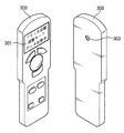
図7は図1に示した本発明の一実施形態に係るリモートコントローラ300の外観を示す図である。
FIG. 7 is a view showing an appearance of the
図7を参照すれば、リモートコントローラ300の後面には光センサ303が付着する。光センサ303はマイクロコントローラ305の制御に応じてフリッカー自動調整モードの間液晶表示装置200の液晶パネル210のフリッカーを感知する。この時、ユーザはリモートコントローラ300の後面に位置した光センサ303が液晶パネル210のフリッカーを正確に感知するように光センサ303を液晶パネル210と近く位置させる。他の実施形態において、液晶パネル210のフレーム領域にリモートコントローラ300を付着することができる溝を形成するか、リモートコントローラ300を立てることができる据置き台を付着する。このような場合、フリッカー自動調整モードの時、リモートコントローラ300を液晶パネル210の溝に付着するか、据置き台に立てる容易な方法でリモートコントローラ300の光センサ303を液晶パネル210に近く位置させることができる。
Referring to FIG. 7, the
図8は本発明の他の実施形態による液晶表示装置の内部構成を示すブロック図である。 FIG. 8 is a block diagram showing an internal configuration of a liquid crystal display device according to another embodiment of the present invention.
図8に示した液晶表示装置は図2に示した液晶表示装置200と類似の構成を有するが、通信回路840の構成及び動作が図2に示した液晶表示装置200内の通信回路240と異なっている。通信回路840は送受信器841、プロセッサ842、メモリ843、及びネットワーク通信部844を含む。
The liquid crystal display device shown in FIG. 8 has a configuration similar to that of the liquid
送受信器841はアンテナ801を通じてリモートコントローラ870から受信された無線信号をデジタル信号に変換してプロセッサ842に提供し、プロセッサ842からリモートコントローラ870に伝送されるデジタル信号を無線信号に変換してアンテナ801を通じてリモートコントローラ870に送る。
The
ネットワーク通信部844はアンテナ802を通じて第1ホスト880と通信し、有線通信チャンネル803を通じて第2ホスト890と通信する。ネットワーク通信部844はアンテナ802と有線通信チャンネル803とを全部具備するか、アンテナ802及び有線通信チャンネル803のうちのいずれか一つのみを具備することができる。第1ホスト880そして/または第2ホスト890はネットワーク通信部844を通じて液晶表示装置800の装置情報(すなわち、製造一連番号、パネル大きさ、解像度、ガンマ値、輝度値など)を受信する。第1ホスト880そして/または第2ホスト890から提供されるガンマ値、輝度値、共通電圧レベルなどのような特性情報はネットワーク通信部844を通じて受信されて制御回路850に提供される。
The
このように図8に示した液晶表示装置800はリモートコントローラ870だけでなく無線そして/または有線で連結された第1ホスト880そして/または第2ホスト890と通信することができる。したがって、ユーザは第1ホスト880そして/または第2ホスト890を利用してディスプレイ装置の特性情報を容易にモニタリング及び調整することができる。
8 can communicate with not only the
図9は本発明のさらに他の実施形態に係るディスプレイシステムを示すブロック図である。 FIG. 9 is a block diagram showing a display system according to still another embodiment of the present invention.
図9に示したディスプレイシステム内の液晶表示装置900は図8に示した液晶表示装置800と類似の構成を有する。図9に示した通信部940内のネットワーク通信部944は外部の第1ホスト980そして/または第2ホスト990だけでなく、映像処理装置995と接続する。映像処理装置995は液晶表示装置200に映像データ及び駆動信号を提供する。
The liquid
ネットワーク通信部944はアンテナ902を通じて第1ホスト980と通信し、有線通信チャンネル903を通じて第2ホスト990と通信する。ネットワーク通信部944はアンテナ902と有線通信チャンネル903とを全部具備するか、アンテナ902及び有線通信チャンネル903のうちのいずれか一つのみを具備することができる。第1ホスト980そして/または第2ホスト990はネットワーク通信部844を通じて液晶表示装置800の装置情報を受信する。第1ホスト980そして/または第2ホスト990から提供されるガンマ値、輝度値、共通電圧レベルなどのような特性情報はネットワーク通信部944を通じて受信されて制御回路950に提供される。
The
図9に示した液晶表示装置900内のネットワーク通信部944は映像処理装置995と通信することができるので、リモートコントローラ970、第1ホスト980、及び第2ホスト990のうちのいずれか一つから提供される制御信号に応じて映像処理装置995の動作特性を変更することができる。
Since the
特に、インターネットのような通信ネットワークを通じて第2ホスト990と液晶表示装置900が連結されている場合、遠隔地で液晶表示装置900の状態をモニタリングすることができ、液晶表示装置900の動作環境を変更することができるので、顧客サポート費用が大幅に減少することができる。
In particular, when the
以上では、本発明に係る回路の構成及び動作を上述の説明及び図に基いて図示したが、これは例をあげて説明したことに過ぎず、本発明の技術的思想を逸脱しない範囲内で多様な変化及び変更が可能であることは勿論である。 In the above, the configuration and operation of the circuit according to the present invention have been illustrated on the basis of the above description and drawings. However, this is only described by way of example, and within the scope not departing from the technical idea of the present invention. Of course, various changes and modifications are possible.
100 ディスプレイシステム
200 液晶表示装置
201、307 送受信端子
210 液晶パネル
220 ゲート駆動回路
230 データ駆動回路
240 通信回路
241、306 送受信器
242 プロセッサ
243 メモリ
250 駆動回路
251 インバータコントローラ
252 輝度センサ
253、304 温度センサ
254 ガンマ電圧発生回路
255 タイミングコントローラ
256 不揮発性メモリ
257 共通電圧発生回路
258 電源電圧発生回路
259 内部インターフェース
260 外部インターフェース
300 リモートコントローラ
301 ディスプレイパネル
302 キーパッド
303 光センサ
305 マイクロコントローラ
844 ネットワーク通信部
880、980 第1ホスト
890、990 第2ホスト
995 映像処理装置
100 display system
200 Liquid
210
230
241, 306
243
251
253, 304
255
257 Common
259
300
302
305 Microcontroller
844
890, 990
Claims (10)
前記ディスプレイ装置は、共通電極と個々の画素に応じた電極とによって液晶層を挟んだ構成を有するディスプレイパネルと、当該ディスプレイ装置の前記ディスプレイパネルの前記共通電極に共通電圧を供給する駆動回路と、前記リモートコントローラから送信されたコマンドに応じたデータを応答する通信回路とを有し、
前記リモートコントローラは、複数のキーを含むとともに押されたキーに対応するコードを発生するキーパッドと、前記ディスプレイ装置と無線通信する送受信器と、前記キーパッドから発生した前記コードに応答して前記ディスプレイ装置に送られる命令を生成して前記送受信器から前記ディスプレイ装置へ送信させ、前記命令に応じて前記送受信器によって前記ディスプレイ装置から受信したデータを前記リモートコントローラの前記ディスプレイパネルに表示させる制御を実行するマイクロコントローラとを有する、ディスプレイシステムであって、
前記命令がフリッカーパターンディスプレイ命令であった場合には、前記ディスプレイ装置の通信回路が、前記駆動回路から前記ディスプレイ装置の前記ディスプレイパネルの前記共通電極に供給される共通電圧の値を読み出し、読み出した共通電圧の値をリモートコントローラへ送信し、前記リモートコントローラのマイクロコントローラが、受信した共通電圧の値を前記リモートコントローラの前記ディスプレイパネルに表示する
ことを特徴とするディスプレイシステム。 Including a display device and a remote controller including a display panel;
The display device includes a display panel having a configuration in which a liquid crystal layer is sandwiched between a common electrode and an electrode corresponding to each pixel; a drive circuit that supplies a common voltage to the common electrode of the display panel of the display device; A communication circuit that responds to data according to a command transmitted from the remote controller,
The remote controller includes a keypad that includes a plurality of keys and generates a code corresponding to the pressed key; a transceiver that wirelessly communicates with the display device; and the response to the code generated from the keypad Control for generating a command to be sent to the display device and transmitting the command from the transceiver to the display device, and displaying the data received from the display device by the transceiver according to the command on the display panel of the remote controller. A display system having a microcontroller to execute,
Wherein when the instruction was a flicker pattern display instruction, the communication circuit of the display device reads the value of the common voltage supplied from the drive circuit to the common electrode of the display panel of the disk-play device, A display system, wherein the read common voltage value is transmitted to a remote controller, and the microcontroller of the remote controller displays the received common voltage value on the display panel of the remote controller.
前記受信した共通電圧の値を調整し、調整された共通電圧の値を前記ディスプレイ装置に送る
ことを特徴とする請求項1に記載のディスプレイシステム。 The remote controller microcontroller is:
The display system according to claim 1, wherein the received common voltage value is adjusted, and the adjusted common voltage value is sent to the display device.
前記駆動回路とデジタルインターフェースを通じて接続され、前記リモートコントローラから受信された前記フリッカーパターンディスプレイ命令に応答してデジタルインターフェースを通じて前記駆動回路から前記共通電圧の値を読み出し、前記リモートコントローラへ送信する
ことを特徴とする請求項1に記載のディスプレイシステム。 The communication circuit of the display device includes:
Is connected through the drive circuit and the digital interface, the read value of the common voltage from the drive circuit via the digital interface in response to the flicker pattern display instructions received from the remote controller, to transmit to the remote controller The display system according to claim 1, wherein:
ことを特徴とする請求項2に記載のディスプレイシステム。 When the communication circuit of the display apparatus receives the adjusted common voltage value from the remote controller, the communication circuit provides the adjusted common voltage value received from the remote controller to the driving circuit. The display system according to claim 2.
ことを特徴とする請求項3に記載のディスプレイシステム。 The display system according to claim 3, wherein the digital interface is a serial digital interface.
ことを特徴とする請求項5に記載のディスプレイシステム。 The display system according to claim 5, wherein the digital interface is a bidirectional I 2 C interface.
前記リモートコントローラは、前記ディスプレイ装置のフリッカー程度を感知するための光センサを含む
ことを特徴とする請求項1に記載のディスプレイシステム。 The communication circuit of the display device displays a flicker pattern on the display panel according to the flicker pattern display command,
The display system according to claim 1, wherein the remote controller includes an optical sensor for detecting a flicker level of the display device.
周辺温度を感知するための温度センサをさらに含むことを特徴とする請求項6に記載のディスプレイシステム。 The remote controller is
The display system of claim 6, further comprising a temperature sensor for sensing the ambient temperature.
前記ディスプレイ装置と無線通信する送受信器と、情報を表示するためのディスプレイパネルと、前記ディスプレイ装置に送られる命令を生成して前記送受信器から前記ディスプレイ装置へ送信させ、前記命令に応じて前記送受信器によって前記ディスプレイ装置から受信したデータを前記ディスプレイパネルに表示させる制御を実行するマイクロコントローラとを含むリモートコントローラとを含み、
前記ディスプレイ装置は、
共通電極と個々の画素に応じた電極とによって液晶層を挟んだ構成を有するディスプレイパネルと、
前記ディスプレイパネルの前記共通電極に共通電圧を供給する駆動回路と、
前記リモートコントローラからフリッカーパターンディスプレイ命令を受信すると、前記駆動回路から当該ディスプレイ装置の前記ディスプレイパネルに前記共通電極に供給される共通電圧の値を読み出し、読み出した共通電圧の値をリモートコントローラへ送信する送受信器と、
通信ネットワークを通じて外部ホストに装置情報を送るためのネットワーク通信ユニットを含むことを特徴とするディスプレイシステム。 A display device;
A transceiver that wirelessly communicates with the display device, a display panel for displaying information, and a command that is sent to the display device are generated and transmitted from the transceiver to the display device, and the transmission / reception is performed according to the command A remote controller including a microcontroller that executes control to display data received from the display device by the display on the display panel;
The display device includes:
A display panel having a configuration in which a liquid crystal layer is sandwiched between a common electrode and an electrode corresponding to each pixel;
A drive circuit for supplying a common voltage to the common electrode of the display panel;
When a flicker pattern display command is received from the remote controller, the common voltage value supplied to the common electrode is read from the drive circuit to the display panel of the display device, and the read common voltage value is transmitted to the remote controller. A transceiver,
Display system comprising a network communication unit for sending the equipment information to the external host through a communications network.
前記ディスプレイ装置と無線通信する送受信器と、情報を表示するためのディスプレイパネルと、前記ディスプレイ装置に送られる命令を生成して前記送受信器から前記ディスプレイ装置へ送信させ、前記命令に応じて前記送受信器によって前記ディスプレイ装置から受信したデータを前記ディスプレイパネルに表示させる制御を実行するマイクロコントローラとを含むリモートコントローラとを含み、
前記ディスプレイ装置は、
共通電極と個々の画素に応じた電極とによって液晶層を挟んだ構成を有するディスプレイパネルと、
当該ディスプレイ装置の前記ディスプレイパネルの前記共通電極に共通電圧を供給する駆動回路と、
前記リモートコントローラからフリッカーパターンディスプレイ命令を受信すると、前記駆動回路から当該ディスプレイ装置の前記ディスプレイパネルの前記共通電極に供給される共通電圧の値を読み出し、読み出した共通電圧の値をリモートコントローラへ送信する送受信器と、
通信ネットワークを通じて外部ホストと通信し、前記外部ホストから入力される制御信号を前記映像処理装置に提供するネットワーク通信ユニットとを含むことを特徴とするディスプレイシステム。 A display device for displaying the video signal in response to the drive signal, including a video processing device for providing the video signal and the drive signal;
A transceiver that wirelessly communicates with the display device, a display panel for displaying information, and a command that is sent to the display device are generated and transmitted from the transceiver to the display device, and the transmission / reception is performed according to the command A remote controller including a microcontroller that executes control to display data received from the display device by the display on the display panel;
The display device includes:
A display panel having a configuration in which a liquid crystal layer is sandwiched between a common electrode and an electrode corresponding to each pixel;
A drive circuit for supplying a common voltage to the common electrode of the display panel of the display device;
When a flicker pattern display command is received from the remote controller, a value of the common voltage supplied to the common electrode of the display panel of the display device is read from the drive circuit, and the read common voltage value is transmitted to the remote controller. A transceiver,
A display system comprising: a network communication unit which communicates with an external host through a communication network and provides a control signal input from the external host to the video processing apparatus.
Applications Claiming Priority (4)
| Application Number | Priority Date | Filing Date | Title |
|---|---|---|---|
| KR10-2005-0115088 | 2005-11-29 | ||
| KR20050115088 | 2005-11-29 | ||
| KR10-2006-0058167 | 2006-06-27 | ||
| KR1020060058167A KR101244644B1 (en) | 2005-11-29 | 2006-06-27 | Display system and operation method thereof |
Publications (3)
| Publication Number | Publication Date |
|---|---|
| JP2007148353A JP2007148353A (en) | 2007-06-14 |
| JP2007148353A5 JP2007148353A5 (en) | 2009-10-08 |
| JP5312729B2 true JP5312729B2 (en) | 2013-10-09 |
Family
ID=38086925
Family Applications (1)
| Application Number | Title | Priority Date | Filing Date |
|---|---|---|---|
| JP2006227202A Active JP5312729B2 (en) | 2005-11-29 | 2006-08-23 | Display system |
Country Status (2)
| Country | Link |
|---|---|
| US (1) | US8054386B2 (en) |
| JP (1) | JP5312729B2 (en) |
Families Citing this family (14)
| Publication number | Priority date | Publication date | Assignee | Title |
|---|---|---|---|---|
| ES2504973T3 (en) | 2010-01-29 | 2014-10-09 | Avery Dennison Corporation | RFID / NFC panel and / or assembly used in intelligent signaling applications and method of use |
| US10977965B2 (en) | 2010-01-29 | 2021-04-13 | Avery Dennison Retail Information Services, Llc | Smart sign box using electronic interactions |
| CN104025556B (en) | 2011-09-01 | 2018-08-10 | 艾利丹尼森公司 | Equipment, system and method for consumer's tracking |
| TWI523144B (en) * | 2011-10-31 | 2016-02-21 | 財團法人國家實驗研究院國家晶片系統設計中心 | Chip structure having resume circuit unit |
| US8630908B2 (en) | 2011-11-02 | 2014-01-14 | Avery Dennison Corporation | Distributed point of sale, electronic article surveillance, and product information system, apparatus and method |
| EP2771845B1 (en) | 2012-09-10 | 2019-01-02 | Avery Dennison Corporation | Method for preventing unauthorized diversion of nfc tags |
| US10540527B2 (en) | 2012-10-18 | 2020-01-21 | Avery Dennison Retail Information Services Llc | Method, system and apparatus for NFC security |
| CN104471969B (en) | 2012-11-19 | 2019-07-30 | 艾利丹尼森公司 | Disable unwarranted NFC security system and method |
| US20140139504A1 (en) * | 2012-11-22 | 2014-05-22 | Shenzhen China Star Optoelectronics Technology Co., Ltd | Method for displaying flicker pattern, method for adjusting common voltage, and lcd module |
| TWI597706B (en) * | 2015-04-17 | 2017-09-01 | 矽創電子股份有限公司 | Display apparatus and computer system |
| KR102331176B1 (en) * | 2015-06-11 | 2021-11-26 | 삼성디스플레이 주식회사 | Display Device |
| CN106683603B (en) * | 2017-01-10 | 2019-08-06 | Oppo广东移动通信有限公司 | A kind of splashette processing method and terminal |
| CN108538258B (en) * | 2017-03-06 | 2023-03-24 | 北京小米移动软件有限公司 | Method and device for adjusting backlight current and display equipment |
| WO2021149495A1 (en) * | 2020-01-23 | 2021-07-29 | 株式会社Jvcケンウッド | Image display device, display control method, and cradle |
Family Cites Families (16)
| Publication number | Priority date | Publication date | Assignee | Title |
|---|---|---|---|---|
| JPS61202597A (en) * | 1985-03-06 | 1986-09-08 | Alps Electric Co Ltd | Remote operating device |
| JP3527311B2 (en) * | 1995-03-03 | 2004-05-17 | 株式会社日立国際電気 | Display board system and control method thereof |
| JP3058049B2 (en) * | 1995-04-19 | 2000-07-04 | 日本電気株式会社 | Counter electrode adjustment circuit for liquid crystal display |
| US6097441A (en) * | 1997-12-31 | 2000-08-01 | Eremote, Inc. | System for dual-display interaction with integrated television and internet content |
| US6784804B1 (en) * | 1998-07-23 | 2004-08-31 | Universal Electronics Inc. | Digital interconnect of entertainment equipment |
| US6407779B1 (en) * | 1999-03-29 | 2002-06-18 | Zilog, Inc. | Method and apparatus for an intuitive universal remote control system |
| JP2001034246A (en) * | 1999-07-23 | 2001-02-09 | Nec Shizuoka Ltd | Computer system |
| US7109974B2 (en) * | 2002-03-05 | 2006-09-19 | Matsushita Electric Industrial Co., Ltd. | Remote control system including an on-screen display (OSD) |
| JP2005065007A (en) * | 2003-08-18 | 2005-03-10 | Matsushita Electric Ind Co Ltd | Television receiver |
| JP4578081B2 (en) * | 2003-09-09 | 2010-11-10 | 三洋電機株式会社 | Display device |
| JP2005204043A (en) * | 2004-01-15 | 2005-07-28 | Seiko Epson Corp | Image display apparatus, information acquisition device thereof, information acquisition/setting method thereof, and content in which setting information thereof is embedded |
| JP2005221569A (en) * | 2004-02-03 | 2005-08-18 | Seiko Epson Corp | Adjustment of counter electrode voltage inputted to liquid crystal panel |
| JP2005258033A (en) * | 2004-03-11 | 2005-09-22 | Funai Electric Co Ltd | Adjustment method of liquid crystal display |
| JP2006201619A (en) * | 2005-01-21 | 2006-08-03 | Funai Electric Co Ltd | Liquid crystal display device |
| JP2006215500A (en) * | 2005-02-07 | 2006-08-17 | Funai Electric Co Ltd | Flicker adjusting device and flicker adjusting method |
| JP3891305B2 (en) * | 2005-03-02 | 2007-03-14 | 船井電機株式会社 | LCD television |
-
2006
- 2006-08-23 JP JP2006227202A patent/JP5312729B2/en active Active
- 2006-11-28 US US11/605,874 patent/US8054386B2/en active Active
Also Published As
| Publication number | Publication date |
|---|---|
| US20070120772A1 (en) | 2007-05-31 |
| JP2007148353A (en) | 2007-06-14 |
| US8054386B2 (en) | 2011-11-08 |
Similar Documents
| Publication | Publication Date | Title |
|---|---|---|
| JP5312729B2 (en) | Display system | |
| JP4860910B2 (en) | Display system, display system driving method, and display system driving apparatus | |
| CN104036713B (en) | Display drive integrated circult and image display system | |
| EP2069881B1 (en) | Method and apparatus for controlling screen of image display device | |
| KR20160046620A (en) | Display driver circuit and display system | |
| KR20180134236A (en) | Digital signage and operating method thereof | |
| TWI647611B (en) | Smart Extended Display Identification Data Simulator | |
| EP1548573A1 (en) | Hierarchical control system for a tiled large-screen emissive display | |
| US20190340983A1 (en) | Display device and displaying method | |
| KR20160015925A (en) | Apparatus for Displaying Image and Driving Method Thereof | |
| CN109036331B (en) | Display screen brightness adjusting method and device and display screen | |
| JP2006072287A (en) | Display apparatus | |
| JP2006072287A5 (en) | ||
| KR20160043477A (en) | A displaying apparatus, a displaying system including a plurality of displaying apparatus and a method of controlling the displaying system | |
| EP2261774A1 (en) | Display apparatus and method | |
| US9710049B2 (en) | Display device, method of driving a display device, and display system | |
| KR101244644B1 (en) | Display system and operation method thereof | |
| TW202133141A (en) | Display device | |
| US11650779B2 (en) | Infinitely expandable display apparatus and driving method thereof | |
| US20110169728A1 (en) | Rotatable display device and image displaying method thereof | |
| TW201009690A (en) | Electronic device and automatic control method thereof | |
| TWM556390U (en) | Smart simulator for extended display identification data | |
| WO2010122633A1 (en) | Liquid crystal monitor device, liquid crystal monitor system, and method for controlling the liquid crystal monitor device | |
| US20100265227A1 (en) | Intelligent digital photo frame | |
| TW202022824A (en) | Low-power-consumption display control method, display control device and information processing device capable of controlling the display of a static picture |
Legal Events
| Date | Code | Title | Description |
|---|---|---|---|
| A521 | Request for written amendment filed |
Free format text: JAPANESE INTERMEDIATE CODE: A523 Effective date: 20090821 |
|
| A621 | Written request for application examination |
Free format text: JAPANESE INTERMEDIATE CODE: A621 Effective date: 20090821 |
|
| A521 | Request for written amendment filed |
Free format text: JAPANESE INTERMEDIATE CODE: A523 Effective date: 20100722 |
|
| A131 | Notification of reasons for refusal |
Free format text: JAPANESE INTERMEDIATE CODE: A131 Effective date: 20120306 |
|
| A521 | Request for written amendment filed |
Free format text: JAPANESE INTERMEDIATE CODE: A523 Effective date: 20120605 |
|
| A131 | Notification of reasons for refusal |
Free format text: JAPANESE INTERMEDIATE CODE: A131 Effective date: 20120821 |
|
| A521 | Request for written amendment filed |
Free format text: JAPANESE INTERMEDIATE CODE: A523 Effective date: 20121023 |
|
| A711 | Notification of change in applicant |
Free format text: JAPANESE INTERMEDIATE CODE: A712 Effective date: 20121213 |
|
| A131 | Notification of reasons for refusal |
Free format text: JAPANESE INTERMEDIATE CODE: A131 Effective date: 20130219 |
|
| A521 | Request for written amendment filed |
Free format text: JAPANESE INTERMEDIATE CODE: A523 Effective date: 20130409 |
|
| TRDD | Decision of grant or rejection written | ||
| A01 | Written decision to grant a patent or to grant a registration (utility model) |
Free format text: JAPANESE INTERMEDIATE CODE: A01 Effective date: 20130625 |
|
| A61 | First payment of annual fees (during grant procedure) |
Free format text: JAPANESE INTERMEDIATE CODE: A61 Effective date: 20130703 |
|
| R150 | Certificate of patent or registration of utility model |
Free format text: JAPANESE INTERMEDIATE CODE: R150 Ref document number: 5312729 Country of ref document: JP Free format text: JAPANESE INTERMEDIATE CODE: R150 |
|
| R250 | Receipt of annual fees |
Free format text: JAPANESE INTERMEDIATE CODE: R250 |
|
| R250 | Receipt of annual fees |
Free format text: JAPANESE INTERMEDIATE CODE: R250 |
|
| R250 | Receipt of annual fees |
Free format text: JAPANESE INTERMEDIATE CODE: R250 |
|
| R250 | Receipt of annual fees |
Free format text: JAPANESE INTERMEDIATE CODE: R250 |
|
| R250 | Receipt of annual fees |
Free format text: JAPANESE INTERMEDIATE CODE: R250 |
|
| R250 | Receipt of annual fees |
Free format text: JAPANESE INTERMEDIATE CODE: R250 |
|
| R250 | Receipt of annual fees |
Free format text: JAPANESE INTERMEDIATE CODE: R250 |
|
| S111 | Request for change of ownership or part of ownership |
Free format text: JAPANESE INTERMEDIATE CODE: R313113 |
|
| R360 | Written notification for declining of transfer of rights |
Free format text: JAPANESE INTERMEDIATE CODE: R360 |
|
| R360 | Written notification for declining of transfer of rights |
Free format text: JAPANESE INTERMEDIATE CODE: R360 |
|
| R371 | Transfer withdrawn |
Free format text: JAPANESE INTERMEDIATE CODE: R371 |
|
| S111 | Request for change of ownership or part of ownership |
Free format text: JAPANESE INTERMEDIATE CODE: R313113 |
|
| R350 | Written notification of registration of transfer |
Free format text: JAPANESE INTERMEDIATE CODE: R350 |
|
| S531 | Written request for registration of change of domicile |
Free format text: JAPANESE INTERMEDIATE CODE: R313531 |
|
| R370 | Written measure of declining of transfer procedure |
Free format text: JAPANESE INTERMEDIATE CODE: R370 |
|
| R250 | Receipt of annual fees |
Free format text: JAPANESE INTERMEDIATE CODE: R250 |