JP5311296B2 - High watt type ceramic metal halide lamp lighting device - Google Patents
High watt type ceramic metal halide lamp lighting device Download PDFInfo
- Publication number
- JP5311296B2 JP5311296B2 JP2011201204A JP2011201204A JP5311296B2 JP 5311296 B2 JP5311296 B2 JP 5311296B2 JP 2011201204 A JP2011201204 A JP 2011201204A JP 2011201204 A JP2011201204 A JP 2011201204A JP 5311296 B2 JP5311296 B2 JP 5311296B2
- Authority
- JP
- Japan
- Prior art keywords
- arc
- voltage
- metal halide
- veff
- arc tube
- Prior art date
- Legal status (The legal status is an assumption and is not a legal conclusion. Google has not performed a legal analysis and makes no representation as to the accuracy of the status listed.)
- Expired - Fee Related
Links
Images


Classifications
-
- H—ELECTRICITY
- H05—ELECTRIC TECHNIQUES NOT OTHERWISE PROVIDED FOR
- H05B—ELECTRIC HEATING; ELECTRIC LIGHT SOURCES NOT OTHERWISE PROVIDED FOR; CIRCUIT ARRANGEMENTS FOR ELECTRIC LIGHT SOURCES, IN GENERAL
- H05B41/00—Circuit arrangements or apparatus for igniting or operating discharge lamps
- H05B41/14—Circuit arrangements
- H05B41/24—Circuit arrangements in which the lamp is fed by high frequency ac, or with separate oscillator frequency
-
- H—ELECTRICITY
- H05—ELECTRIC TECHNIQUES NOT OTHERWISE PROVIDED FOR
- H05B—ELECTRIC HEATING; ELECTRIC LIGHT SOURCES NOT OTHERWISE PROVIDED FOR; CIRCUIT ARRANGEMENTS FOR ELECTRIC LIGHT SOURCES, IN GENERAL
- H05B41/00—Circuit arrangements or apparatus for igniting or operating discharge lamps
- H05B41/02—Details
- H05B41/04—Starting switches
- H05B41/042—Starting switches using semiconductor devices
-
- H—ELECTRICITY
- H01—ELECTRIC ELEMENTS
- H01J—ELECTRIC DISCHARGE TUBES OR DISCHARGE LAMPS
- H01J61/00—Gas-discharge or vapour-discharge lamps
- H01J61/82—Lamps with high-pressure unconstricted discharge having a cold pressure > 400 Torr
- H01J61/827—Metal halide arc lamps
-
- H—ELECTRICITY
- H01—ELECTRIC ELEMENTS
- H01J—ELECTRIC DISCHARGE TUBES OR DISCHARGE LAMPS
- H01J61/00—Gas-discharge or vapour-discharge lamps
- H01J61/92—Lamps with more than one main discharge path
-
- H—ELECTRICITY
- H05—ELECTRIC TECHNIQUES NOT OTHERWISE PROVIDED FOR
- H05B—ELECTRIC HEATING; ELECTRIC LIGHT SOURCES NOT OTHERWISE PROVIDED FOR; CIRCUIT ARRANGEMENTS FOR ELECTRIC LIGHT SOURCES, IN GENERAL
- H05B41/00—Circuit arrangements or apparatus for igniting or operating discharge lamps
- H05B41/14—Circuit arrangements
- H05B41/26—Circuit arrangements in which the lamp is fed by power derived from dc by means of a converter, e.g. by high-voltage dc
- H05B41/28—Circuit arrangements in which the lamp is fed by power derived from dc by means of a converter, e.g. by high-voltage dc using static converters
- H05B41/288—Circuit arrangements in which the lamp is fed by power derived from dc by means of a converter, e.g. by high-voltage dc using static converters with semiconductor devices and specially adapted for lamps without preheating electrodes, e.g. for high-intensity discharge lamps, high-pressure mercury or sodium lamps or low-pressure sodium lamps
- H05B41/2885—Static converters especially adapted therefor; Control thereof
-
- H—ELECTRICITY
- H05—ELECTRIC TECHNIQUES NOT OTHERWISE PROVIDED FOR
- H05B—ELECTRIC HEATING; ELECTRIC LIGHT SOURCES NOT OTHERWISE PROVIDED FOR; CIRCUIT ARRANGEMENTS FOR ELECTRIC LIGHT SOURCES, IN GENERAL
- H05B41/00—Circuit arrangements or apparatus for igniting or operating discharge lamps
- H05B41/14—Circuit arrangements
- H05B41/26—Circuit arrangements in which the lamp is fed by power derived from dc by means of a converter, e.g. by high-voltage dc
- H05B41/28—Circuit arrangements in which the lamp is fed by power derived from dc by means of a converter, e.g. by high-voltage dc using static converters
- H05B41/288—Circuit arrangements in which the lamp is fed by power derived from dc by means of a converter, e.g. by high-voltage dc using static converters with semiconductor devices and specially adapted for lamps without preheating electrodes, e.g. for high-intensity discharge lamps, high-pressure mercury or sodium lamps or low-pressure sodium lamps
- H05B41/292—Arrangements for protecting lamps or circuits against abnormal operating conditions
- H05B41/2928—Arrangements for protecting lamps or circuits against abnormal operating conditions for protecting the lamp against abnormal operating conditions
-
- Y—GENERAL TAGGING OF NEW TECHNOLOGICAL DEVELOPMENTS; GENERAL TAGGING OF CROSS-SECTIONAL TECHNOLOGIES SPANNING OVER SEVERAL SECTIONS OF THE IPC; TECHNICAL SUBJECTS COVERED BY FORMER USPC CROSS-REFERENCE ART COLLECTIONS [XRACs] AND DIGESTS
- Y02—TECHNOLOGIES OR APPLICATIONS FOR MITIGATION OR ADAPTATION AGAINST CLIMATE CHANGE
- Y02B—CLIMATE CHANGE MITIGATION TECHNOLOGIES RELATED TO BUILDINGS, e.g. HOUSING, HOUSE APPLIANCES OR RELATED END-USER APPLICATIONS
- Y02B20/00—Energy efficient lighting technologies, e.g. halogen lamps or gas discharge lamps
Abstract
Description
本発明は、高ワットタイプのセラミックメタルハライドランプ照明装置に関する。更に具体的には、本発明は、複数本(例えば、2本)の発光管を直列に接続した高ワットタイプのセラミックメタルハライドランプ照明装置に関する。 The present invention relates to a high watt type ceramic metal halide lamp illumination device. More specifically, the present invention relates to a high watt type ceramic metal halide lamp illumination device in which a plurality of (for example, two) arc tubes are connected in series.
最近、高ワットタイプのセラミックメタルハライドランプが、スポーツ施設、競技場の照明等に、ランプを水平に設置した形式(水平点灯)で使用されることが多い。このような高ワットタイプのランプに使用されている大きなサイズの発光管は、アーク長が長くなるため、アークが中心軸線から外れて湾曲して浮上し、セラミック容器を加熱しクラックの原因となるおそれがあった。 Recently, high watt type ceramic metal halide lamps are often used in the form of horizontal installation of lamps (horizontal lighting) in sports facilities and stadium lighting. The arc tube of a large size used in such a high watt type lamp has a long arc length, so that the arc is curved and floats off the central axis, heating the ceramic container and causing cracks. There was a fear.
また、高ワットタイプのセラミックメタルハライドランプは、セラミック放電容器に封止する導電性材料の太さを太くしなければならないが、導電性材料が太いと、点灯中の温度により膨張したときに、セラミック放電容器と導電性材料との熱膨張率の差から、クラックが発生するおそれがある。 In addition, the high watt type ceramic metal halide lamp has to increase the thickness of the conductive material sealed in the ceramic discharge vessel, but if the conductive material is thick, when it expands due to the temperature during lighting, the ceramic Cracks may occur due to the difference in coefficient of thermal expansion between the discharge vessel and the conductive material.
更に、比較的大きなサイズの発光管は、セラミック容器の製造が比較的困難であり、製造コストが高価になるという欠点もあった。 Further, the arc tube of a relatively large size has a drawback that it is relatively difficult to manufacture the ceramic container and the manufacturing cost is expensive.
特許文献1に倣って、例えば、700W用発光管を、2本の汎用タイプの360W用発光管を電気的に直列接続して置き換えるアイデアが生まれた。これにより、アーク浮上の問題、高価な製造コストの問題等は解決される。
Following
しかし、2本のセラミック製発光管を電気的に直列接続したセラミックメタルハライドランプを試作して従来の安定器を用いて点灯したところ、グロー放電からアーク放電に移行せずに、グロー放電のままランプが温度上昇し、消灯してしまうという問題があることが判明した。 However, when a ceramic metal halide lamp in which two ceramic arc tubes were electrically connected in series was prototyped and lit using a conventional ballast, the lamp did not change from glow discharge to arc discharge. It turned out that there was a problem that the temperature rose and turned off.
従って、本発明は、スムーズに点灯可能な、複数本(例えば、2本)の発光管を直列接続した高ワットタイプのセラミックメタルハライドランプ照明装置を提供することを目的とする。 Accordingly, an object of the present invention is to provide a high watt type ceramic metal halide lamp illuminating device in which a plurality of (for example, two) arc tubes that can be smoothly turned on are connected in series.
本発明に係る高ワットタイプのセラミックメタルハライドランプ照明装置は、一次入力電圧を入力し、二次電圧を出力する安定器と、電気的に直列接続された複数本の発光管を外球内部に有し、前記安定器からの二次電圧を入力して点灯するランプとを備え、前記安定器からの二次出力電圧は、少なくとも、その波形が、最大値/実効値の比率(Vmax/Veff)>20.5を満たすものである。 A high watt type ceramic metal halide lamp illuminating device according to the present invention has a ballast for inputting a primary input voltage and outputting a secondary voltage, and a plurality of electrically connected arc tubes in an outer bulb. The secondary output voltage from the ballast is at least the ratio of the maximum value / effective value (Vmax / Veff). > 2 0.5 is satisfied.
更に、上記セラミックメタルハライドランプ照明装置では、前記安定器からの二次出力電圧は、少なくとも、その波形が、最大値/実効値の比率(Vmax/Veff)>30.5を満たすものであってよい。 Further, the ceramic metal halide lamp lighting device, the secondary output voltage from the ballast is at least, its waveform is the ratio of the maximum value / effective value (Vmax / Veff)> 3 may be one satisfying 0.5.
更に、上記セラミックメタルハライドランプ照明装置では、更に、前記安定器からの二次出力電圧は、(a)実効値が、各発光管のグロー放電維持電圧の総和以上あり、(b)最大値が、各発光管のアーク放電移行電圧の総和以上であってよい。 Further, in the ceramic metal halide lamp lighting device, the secondary output voltage from the ballast is further, (a) effective value is more than the sum of glow discharge sustaining voltage of each arc tube, (b) maximum value, It may be greater than or equal to the sum of arc discharge transition voltages of each arc tube.
更に、上記セラミックメタルハライドランプ照明装置では、更に、前記安定器からの二次出力電圧は、(a)実効値が、各発光管のグロー放電維持電圧の総和以上であり、且つ各発光管のアーク放電移行電圧の総和未満であり、(b)最大値が、各発光管のアーク放電移行電圧の総和以上であり、且つ各発光管の絶縁破壊電圧の総和未満であってよい。 Further, in the ceramic metal halide lamp lighting device, the secondary output voltage from the ballast is further: (a) the effective value is equal to or greater than the sum of the glow discharge sustaining voltages of each arc tube, and the arc of each arc tube It is less than the sum of the discharge transition voltages, and (b) the maximum value may be greater than or equal to the sum of the arc discharge transition voltages of each arc tube and less than the sum of the dielectric breakdown voltages of each arc tube.
更に、上記セラミックメタルハライドランプ照明装置では、高ワットタイプの700W用発光管の代わりに、2本の汎用タイプの360W用発光管を電気的に直列接続して用いる場合、前記三角波交流電圧は、最大値で表示すると、500V≦Vmax(三角波)となり、実効値で表示すると、260V≦Veff(三角波)となってよい。
Furthermore, in the ceramic metal halide lamp lighting device, when two general-
更に、上記セラミックメタルハライドランプ照明装置では、高ワットタイプの700W用発光管の代わりに、2本の汎用タイプの360W用発光管を電気的に直列接続して用いる場合、前記三角波は、最大値で表示すると、500V≦Vmax(三角波)であり、実効値で表示すると、260V≦Veff(三角波)≦500Vであってよい。
Further, in the ceramic metal halide lamp lighting device, when two general-
更に、上記セラミックメタルハライドランプ照明装置では、前記安定器からの二次出力電圧は、三角波交流電圧であってよい。 Furthermore, in the ceramic metal halide lamp lighting device, the secondary output voltage from the ballast may be a triangular wave AC voltage.
本発明によれば、スムーズに点灯可能な、複数本(例えば、2本)の発光管を直列接続した高ワットタイプのセラミックメタルハライドランプ照明装置を提供することが出来る。 ADVANTAGE OF THE INVENTION According to this invention, the high watt type ceramic metal halide lamp illuminating device which connected in series the several (for example, two) arc tube which can be lighted smoothly can be provided.
以下、本発明に係る高ワットタイプのセラミックメタルハライドランプ照明装置の実施形態に関して、添付の図面を参照しながら詳細に説明する。なお、図中、同じ要素に対しては同じ符号を付与して、重複した説明を省略する。なお、本実施形態は、本発明を説明するための例示であって、本発明の技術的範囲を何等限定するものではないことを承知されたい。 Hereinafter, embodiments of a high watt type ceramic metal halide lamp lighting device according to the present invention will be described in detail with reference to the accompanying drawings. In addition, in the figure, the same code | symbol is provided with respect to the same element, and the duplicate description is abbreviate | omitted. It should be noted that the present embodiment is an example for explaining the present invention and does not limit the technical scope of the present invention.
[HIDランプ内の放電現象]
本発明の理解を容易にするため、最初に、HIDランプ(高輝度放電ランプ)の発光管内で発生する放電現象を簡単に説明する。HIDランプは、水銀ランプ、メタルハライドランプ、高圧ナトリウムランプ等の総称であり、メタルハライドランプの内でセラミックス製発光管を備えたランプをセラミックメタルハライドランプと称している。
[Discharge phenomenon in HID lamp]
In order to facilitate understanding of the present invention, first, the discharge phenomenon that occurs in the arc tube of an HID lamp (high intensity discharge lamp) will be briefly described. The HID lamp is a generic term for mercury lamps, metal halide lamps, high-pressure sodium lamps, and the like, and among the metal halide lamps, a lamp having a ceramic arc tube is called a ceramic metal halide lamp.
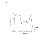
HIDランプに使用される発光管の電極間に印加された交流電圧を徐々に高くすると、或る限界を超えると電極間に強い光が観察される放電現象が生じる。図1は、発光管内の放電現象を簡単に説明する図であり、縦軸に発光管端子電圧Vをとり、これに対応する放電電流Aを横軸にとって、放電の電流−電圧特性を説明する。なお、縦軸の発光管端子電圧Vに具体的な数値が記載されてないのは、発光管の定格電力、サイズ、電極間距離、封入ガスの種類及び圧力等により、その数値が異なるからである。 When the AC voltage applied between the electrodes of the arc tube used in the HID lamp is gradually increased, a discharge phenomenon is observed in which strong light is observed between the electrodes when a certain limit is exceeded. FIG. 1 is a diagram for briefly explaining the discharge phenomenon in the arc tube. The arc-tube terminal voltage V is taken on the vertical axis, and the discharge current A corresponding thereto is taken on the horizontal axis to explain the current-voltage characteristics of the discharge. . The specific value is not described in the arc tube terminal voltage V on the vertical axis because the value varies depending on the rated power of the arc tube, the size, the distance between electrodes, the type and pressure of the sealed gas, and the like. is there.
発光管端子電圧を徐々に高くすると、点(o)〜(a)の領域は、放電開始前で光は全く発しない暗放電領域である。 When the arc tube terminal voltage is gradually increased, the areas of points (o) to (a) are dark discharge areas where no light is emitted before the start of discharge.
点(a)を超えることを絶縁破壊という。安定器(図5参照)からランプに対して、ベース電圧(例えば、200〜300V)に対して瞬時的に非常に高圧なパルス電圧(例えば、3.7〜4.5kV)を重畳して印加し、絶縁破壊を行っている。なお、この高圧パルス電圧は、絶縁破壊後に直ちに終了する。 Overcoming point (a) is called dielectric breakdown. A very high voltage pulse voltage (eg, 3.7 to 4.5 kV) is instantaneously superimposed on the base voltage (eg, 200 to 300 V) from the ballast (see FIG. 5) to the lamp. And dielectric breakdown. The high voltage pulse voltage is immediately terminated after the dielectric breakdown.
点(b)〜(c)の領域は、電圧が比較的高く電流が比較的小さなグロー放電領域であり、陰極電極からの2次電子放出のみを放電電流としている。 The region of points (b) to (c) is a glow discharge region where the voltage is relatively high and the current is relatively small, and only secondary electron emission from the cathode electrode is used as the discharge current.
点(e)以降の領域は、電圧が比較的低く電流が比較的大きなアーク放電領域である。アーク放電維持電圧は、グロー放電維持電圧に比較して、低い電圧である。アーク放電領域では、陰極電極の冷電子放出又は熱電子放出を放電電流としている。HIDランプは、発光管内の金属電子高圧蒸気中のアーク放電を利用したランプである。 The area after the point (e) is an arc discharge area where the voltage is relatively low and the current is relatively large. The arc discharge sustaining voltage is lower than the glow discharge sustaining voltage. In the arc discharge region, the discharge current is cold electron emission or thermal electron emission of the cathode electrode. The HID lamp is a lamp that uses arc discharge in the metal electron high-pressure vapor in the arc tube.
グロー放電からアーク放電に移行するためには、ピーク点(d)(以下、本出願書類では「アーク放電移行電圧」という。)を超える電極間電圧が必要である。従って、上述したグロー放電からアーク放電に移行しなかった問題は、アーク放電移行電圧を超える電圧が電極間に印加されなかったことによる。 In order to shift from glow discharge to arc discharge, a voltage between electrodes exceeding a peak point (d) (hereinafter referred to as “arc discharge transition voltage” in the present application document) is required. Therefore, the problem of not shifting from the glow discharge to the arc discharge described above is that a voltage exceeding the arc discharge transition voltage was not applied between the electrodes.
なお、この問題は、特許文献1に開示する高圧ナトリウム蒸気放電灯では生じない。これは、セラミックメタルハライドランプに比較して、高圧水銀ランプ及び高圧ナトリウムランプでは、電極にエミッタが塗布されているためグロー放電電圧が比較的低く、これに伴いアーク放電移行電圧が比較的低いためであった。更に、高圧水銀ランプ及び高圧ナトリウムランプに使用されている発光管は石英製発光管である。石英製発光管は、セラミック製発光管に比較して、発光管内に封入された金属ハロゲン化物と反応し易い欠点を有する反面、熱衝撃に対して強固である長所を有するためであった。
This problem does not occur in the high-pressure sodium vapor discharge lamp disclosed in
[第1実施形態]
(高ワットタイプのセラミックメタルハライドランプ)
第1実施形態に係る高ワットタイプのセラミックメタルハライドランプは、2本の汎用発光管を使用した例である。
[First Embodiment]
(High watt type ceramic metal halide lamp)
The high watt type ceramic metal halide lamp according to the first embodiment is an example using two general-purpose arc tubes.
図2は、本実施形態に係る高ワットタイプ(例えば、700〜1,000W)のセラミックメタルハライドランプ10の中心軸線に沿った要部断面図である。メタルハライドランプ10は、口金14を形成した外球16内に、支柱18に支持された2本の発光管12−1,12−2が、電気的に直列接続されている。支柱18は、ステム20に固定されている。外球16内は、真空に保持されている。なお、図2には示されていないが、外球16の内部には、安定器(図5参照)から出力される交流電圧に対して、絶縁破壊を行うための高圧パルス電圧を瞬時的に発生して重畳する始動回路(イグナイタ)が備えられている。
FIG. 2 is a cross-sectional view of the main part along the central axis of the ceramic
図3は、図2に示すランプに使用される発光管12−1,12−2の中心軸線に沿った要部断面図である。発光管12−1,12−2は、断面で見てほぼ楕円形状に形成された発光部12aと、その両端に夫々接合された細管部12b,12cとが一体成型されている。発光部12aはセラミックスから形成され、中央部から細管接合部に向けて徐々に内径が小さくなっている。各細管部12b,12cには、電極22a、22bが夫々挿入されている。両電極間の間隙が、アーク長Lに相当する。
FIG. 3 is a cross-sectional view of an essential part along the central axis of arc tubes 12-1 and 12-2 used in the lamp shown in FIG. The light emitting tubes 12-1 and 12-2 are integrally formed with a
上述したように、発光管は、高ワットタイプ(例えば、700W発光管,1,000W発光管)になるとサイズが大きくなるため、アーク長が長くなり、アークの浮上が起こり、セラミック容器を加熱しクラックの原因となる。また、大きなサイズのセラミック容器は、製造が比較的困難であり、製造コストが高価になるという欠点がある。これに対して、現在、比較的大量に使用され、従って市場に於いて比較的廉価に入手可能な発光管として、360W発光管があり、次に、270W発光管、440W発光管等がある。図2のランプでは、このような汎用発光管を使用している。 As described above, since the arc tube becomes larger in size when it becomes a high watt type (for example, 700W arc tube, 1,000W arc tube), the arc length becomes long, the arc floats, and the ceramic container is heated. Cause cracks. In addition, a large-sized ceramic container is disadvantageous in that it is relatively difficult to manufacture and the manufacturing cost is high. On the other hand, there are 360 W arc tubes, and 270 W arc tubes, 440 W arc tubes, etc. as arc tubes that are currently used in relatively large quantities and are therefore relatively inexpensive in the market. The general-purpose arc tube is used in the lamp of FIG.
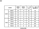
図4は、図3の発光管の特性を示す図表である。ここには、汎用360W用発光管として4種類のデータ「360W−1〜4」が示されている。夫々のアーク長Lは、16〜22mmの範囲にある。これ以降説明するデータは、発光管「360W−4」を使用して行った実験データである。
FIG. 4 is a chart showing characteristics of the arc tube of FIG. Here, four types of data “360W-1 to 4” are shown as general-
なお、比較のため、高ワットタイプの700W発光管として4種類のデータ「700W−1〜4」も添付する。これらのアーク長Lは、39mmと比較的長い。アーク長Lが長いため、水平点灯した場合、発光管内のガスの対流によりアークが浮上し大きく湾曲する。
For comparison, four types of data “700W-1 to 4” are also attached as a high-
図5は、セラミックメタルハライドランプ照明装置の回路の概略図である。電源24は、商用交流電源200V(特別な場合、100V)である。安定器26は、トランスとチョークコイルを使用して、所定の安定器二次電圧を出力する。
Figure 5 is a schematic diagram of a circuit of a ceramic metal halide lamp lighting equipment. The
本発明者等は、2本の直列接続の発光管を、グロー放電からアーク放電にスムーズに移行させるために、次の条件を満たすことが必要であるとの結論に達した。図1を参照すると、(a)2本の発光管12−1,12−2の両端に印加される端子間電圧が、定常値として、各発光管のグロー放電維持電圧(点b〜c参照)の総和以上あり、(b)瞬時値として、各発光管のアーク放電移行電圧(点d参照)の総和以上あること、である。 The present inventors have concluded that the following conditions must be satisfied in order to smoothly transition the two arc-connected arc tubes from glow discharge to arc discharge. Referring to FIG. 1, (a) a voltage between terminals applied to both ends of two arc tubes 12-1 and 12-2 is a steady value, and a glow discharge sustaining voltage of each arc tube (see points b to c). ), And (b) the instantaneous value is equal to or greater than the sum of arc discharge transition voltages (see point d) of each arc tube.
なお、2本の発光管12−1,12−2の電気的特性が全く同じであれば、安定器26の二次出力電圧は、各発光管12−1,12−2の夫々の端子間電圧は1/2ずつ印加される。現実問題としては、各発光管の電気的特性にはバラツキがある。しかし、端子間電圧が、定常値として、各発光管のグロー放電維持電圧の総和以上あれば、グロー放電は維持される。同様に、瞬時値として、各発光管のアーク放電移行電圧の総和以上あれば、必ず、一方の発光管はアーク放電に移行し、アーク放電に移行した発光管は負性抵抗を示し、これに印加される端子電圧は急激に低下する結果、更に大きな電圧が他方の発光管に印加することになり、他方の発光管もアーク放電に移行する。
If the electric characteristics of the two arc tubes 12-1 and 12-2 are exactly the same, the secondary output voltage of the
このため、(a)実効値が、各発光管のグロー放電維持電圧の総和以上あり、(b)最大値が、各発光管をアーク放電移行電圧の総和以上ある、安定器の二次出力電圧の検討を行った。 For this reason, (a) the effective value is equal to or greater than the sum of glow discharge sustaining voltages of each arc tube, and (b) the maximum value is equal to or greater than the sum of arc discharge transition voltages of each arc tube, Was examined.
その結果、安定器の二次出力電圧の波形を変えることにより、この条件を満たすこととしたのである。即ち、通常の安定器の二次出力電圧の波形は、正弦波である。これを、例えば三角波に代えることにより、上記条件を満たしたのである。なお、説明のため、従来の正弦波に加えて、矩形波の例も交えて、三角波の利点を説明する。 As a result, this condition is satisfied by changing the waveform of the secondary output voltage of the ballast. That is, the waveform of the secondary output voltage of a normal ballast is a sine wave. The above condition is satisfied by replacing this with, for example, a triangular wave. For the sake of explanation, in addition to the conventional sine wave, the advantage of the triangular wave will be described using a rectangular wave example.
図6は、安定器の二次出力電圧として検討した各種電圧波形を示す図である。ここで、(A)は矩形波の電圧波形、(B)は正弦波の電圧波形、(C)は三角波の電圧波形である。三角波の場合、その波形には変形がある。波形が、正三角形の場合は、波形の高さhと底辺aの比は、h/a=30.5である。オシロ波形で時間軸を合わせた場合、正三角形に比べて、高さhが比較的高い二等辺三角形の場合、h/a>30.5となる。正三角形に比べて、高さhが比較的低い二等辺三角形の場合、h/a<30.5となる。本出願書類では、用語「三角波」は、正三角形波及びこのような変形の三角波を含むことを承知されたい。 FIG. 6 is a diagram showing various voltage waveforms studied as the secondary output voltage of the ballast. Here, (A) is a rectangular wave voltage waveform, (B) is a sine wave voltage waveform, and (C) is a triangular wave voltage waveform. In the case of a triangular wave, the waveform is deformed. When the waveform is an equilateral triangle, the ratio of the waveform height h to the base a is h / a = 30.5 . When the time axis is matched with the oscilloscope waveform, h / a> 30.5 is obtained in the case of an isosceles triangle having a relatively high height h compared to the regular triangle. In the case of an isosceles triangle having a relatively low height h compared to an equilateral triangle, h / a < 30.5 . In this application, it should be understood that the term “triangular wave” includes equilateral triangular waves and triangular waves of such deformations.
矩形波電圧に関しては、実効値と最大値の関係は、Vmax(矩形波)=Veff(矩形波)となる。正弦波電圧に関しては、実効値と最大値の関係は、Vmax(正弦波)=20.5Veff(正弦波)=1.414・Veff(正弦波)となる。これに対して、今回の実験で使用した三角波電圧に関しては、実効値と最大値の関係は、Vmax(三角波)=1.941・Veff(三角波)であった。 Regarding the rectangular wave voltage, the relationship between the effective value and the maximum value is Vmax (rectangular wave) = Veff (rectangular wave) . Regarding the sine wave voltage, the relationship between the effective value and the maximum value is Vmax (sine wave) = 2 0.5 Veff (sine wave) = 1.414 · Veff (sine wave) . On the other hand, regarding the triangular wave voltage used in this experiment, the relationship between the effective value and the maximum value was Vmax (triangular wave) = 1.941 · Veff (triangular wave) .
同じ実効値Veff(例えば、280V)の場合、矩形波の最大値は、実効値と同じであり、Vmax(矩形波)=Veff(矩形波)=280Vとなる。正弦波の最大値は、実効値の1.414倍であり、Vmax(正弦波)=1.414・Veff(正弦波)=396Vとなる。これに対して、三角波の最大値は、実効値の1.941倍であり、Vmax(三角波)=1.914・Veff(三角波)=543Vとなり、同じ実効値でも最大値が高くなり、比較的高いアーク放電移行電圧を容易に確保できる。 In the case of the same effective value Veff (for example, 280V), the maximum value of the rectangular wave is the same as the effective value, and Vmax (rectangular wave) = Veff (rectangular wave) = 280V. The maximum value of the sine wave is 1.414 times the effective value, and Vmax (sine wave) = 1.414 · Veff (sine wave) = 396V. On the other hand, the maximum value of the triangular wave is 1.941 times the effective value, Vmax (triangular wave) = 1.914 · Veff (triangular wave) = 543 V, and the maximum value is relatively high even with the same effective value. A high arc discharge transition voltage can be easily secured.
この結果より、従来使用されていた正弦波の最大値/実効値の比率(Vmax(正弦波)/Veff(正弦波)=20.5)より大きな比率の波形が必要であることが判明した。これが、三番目の条件、(c) その波形が、最大値/実効値の比率(Vmax/Veff)>20.5を満たすものである。このような波形として、典型的には、二次出力電圧の最大値と実効値の比率(Vmax/Veff)が大きな三角波がある。 From this result, it was found that conventionally used have sine wave of the maximum value / effective value of the ratio (Vmax (sine wave) / Veff (sine wave) = 2 0.5) is required waveform ratio higher than. This is the third condition, the (c) the waveform, satisfies the maximum value / ratio of the effective value (Vmax / Veff)> 2 0.5 . As such a waveform, there is typically a triangular wave having a large ratio (Vmax / Veff) between the maximum value and the effective value of the secondary output voltage.
更に、小形で低出力の安定器とするためには、図1から分かるように、二次出力電圧の最大値Vmaxは、絶縁破壊電圧(図1の点a)より低くてよい(即ち、Vmax<各発光管の絶縁破壊電圧の総和)。また、二次出力電圧の実効値Veffは、アーク放電移行電圧(図1の点d)より低くてよい(即ち、Veff<各発光管のアーク放電移行電圧の総和)。 Further, in order to obtain a small and low output ballast, as can be seen from FIG. 1, the maximum value Vmax of the secondary output voltage may be lower than the breakdown voltage (point a in FIG. 1) (ie, Vmax). <Total of dielectric breakdown voltage of each arc tube>. Further, the effective value Veff of the secondary output voltage may be lower than the arc discharge transition voltage (point d in FIG. 1) (that is, Veff <the total arc discharge transition voltage of each arc tube).
図7は、図6に示す各電圧波形をパラメータとした、安定器二次電圧の実効値−最大値の特性である。ここに、2本の「360W用発光管−4」を使用して、アーク移行の可否の実験結果を表示してある。記号丸「○」はアーク放電に移行可、記号バツ「×」はアーク放電に移行不可の実験データを示している。 FIG. 7 shows the characteristic of the effective value-maximum value of the ballast secondary voltage using the voltage waveforms shown in FIG. 6 as parameters. Here, the experimental results of whether or not arc transfer is possible are displayed using two “360W arc tube-4”. The symbol “◯” indicates experimental data that can be transferred to arc discharge, and the symbol “×” indicates experimental data that cannot be transferred to arc discharge.
図7に示すように、三角波の二次出力電圧では、Veff(三角波)=260V,280V,300V,320,…で、アーク放電移行可が確認された。これに対して、正弦波では、Veff(正弦波)≧300Vでアーク放電移行可となった。矩形波も同様に、Veff(矩形波)≧300Vでアーク放電移行可となった。二次出力電圧が三角波の場合、他の波形と比較して、同じ実効値でも高い最大値が得られ、アーク放電移行が実現できる。これは、比較的小型で、そのため廉価な安定器を使用できることを意味する。 As shown in FIG. 7, in the secondary output voltage of the triangular wave , it was confirmed that arc discharge transition was possible at Veff (triangular wave) = 260V, 280V, 300V, 320,. On the other hand, in the case of the sine wave, the arc discharge can be transferred when Veff (sine wave) ≧ 300V. Similarly, the rectangular wave can be transferred to arc discharge when Veff ( rectangular wave ) ≧ 300V. When the secondary output voltage is a triangular wave, a high maximum value can be obtained even with the same effective value as compared with other waveforms, and arc discharge transition can be realized. This means that relatively small ballasts can therefore be used.
なお、日本国内の法規制「電気設備技術基準」によれば、使用電圧が低圧の電路の電線相互間及び電路と大地との間の要求絶縁抵抗は、300V以下とこれを超えるものとでは異なっている。要求絶縁抵抗が高くなると、安定器のコストが高くなり、好ましくない。従って、日本国内に於いては、700W用発光管の代わりに、2本の汎用タイプの360W用発光管を電気的に直列接続して用いる場合、実効値で表示すると、260V≦Veff(三角波)≦300Vとしてもよい。但し、これは法規制に関する制限事項であり、発明の技術的内容に関する制限事項ではない。
In addition, according to the Japanese legal regulations “Electrical Equipment Technical Standards”, the required insulation resistance between electric wires of low-voltage circuit and between the electric circuit and the earth differs between 300V and below. ing. If the required insulation resistance is increased, the cost of the ballast is increased, which is not preferable. Therefore, in Japan, when two general-
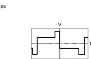
以上、安定器の二次出力電圧の波形が三角波であるとして説明した。しかし、波形は三角波に限定されないことを承知されたい。安定器二次電圧に要求される条件は、(a)実効値が、各発光管のグロー放電維持電圧の総和以上あり、(b)最大値が、各発光管をアーク放電移行電圧の総和以上であり、(c) その波形が、最大値/実効値の比率(Vmax/Veff)>20.5を満たすものである。図8は、安定器二次電圧の波形の他の例である。例えば、図8に示すような2種類の矩形波を重畳した二次出力電圧であっても、上記条件を満たすことができる。 The description has been given above assuming that the waveform of the secondary output voltage of the ballast is a triangular wave. However, it should be appreciated that the waveform is not limited to a triangular wave. The conditions required for the ballast secondary voltage are: (a) the effective value is greater than or equal to the sum of glow discharge sustaining voltages of each arc tube, and (b) the maximum value is greater than or equal to the sum of arc discharge transition voltages for each arc tube. in and, (c) the waveform is, it satisfies the maximum value / ratio of the effective value (Vmax / Veff)> 2 0.5 . FIG. 8 is another example of the waveform of the ballast secondary voltage. For example, the above condition can be satisfied even with a secondary output voltage in which two types of rectangular waves as shown in FIG. 8 are superimposed.
[第2実施形態]
第2実施形態は、図示していないが、発光管を3本以上電気的に直列接続した例である。例えば、1,000Wの高ワットタイプのランプの発光管を、3本の汎用360W発光管で置き換えることができる。安定器の二次電圧は、(a)実効値が、各発光管のグロー放電維持電圧の総和以上あり、(b)最大値が、各発光管をアーク放電移行電圧の総和以上であり、(c) その波形が、最大値/実効値の比率(Vmax/Veff)>20.5を満たすものである。
[Second Embodiment]
Although not shown, the second embodiment is an example in which three or more arc tubes are electrically connected in series. For example, a 1,000 W high watt type lamp arc tube can be replaced with three
この場合、汎用の発光管を利用できるメリットがある。反面、ディメリットとして、例えば、3本の360W用発光管のグロー放電維持電圧の総和及びアーク放電移行電圧の総和は、1,000W用発光管のグロー放電維持電圧及びアーク放電移行電圧より夫々大きくなるため、それに応じた二次出力電圧が可能な安定器を用意しなければならない。 In this case, there is an advantage that a general-purpose arc tube can be used. On the other hand, as a disadvantage, for example, the sum of the glow discharge sustaining voltages and arc discharge transition voltages of the three 360 W arc tubes are larger than the glow discharge sustain voltage and arc discharge transition voltage of the 1,000 W arc tube, respectively. Therefore, a ballast capable of a secondary output voltage corresponding to that must be prepared.
[第3実施形態]
第3実施形態は、図示していないが、異なる種類の複数本の発光管を電気的に直列接続した例である。例えば、現在、汎用発光管として、270W発光管、360W発光管、440W発光管等が入手可能である。例えば、(270W発光管+360W発光管+440W発光管)を直列接続して、1,000Wの高ワットタイプのランプを実現してもよい。この場合のメリット及びディメリットは、第2実施形態で説明したのと同様である。
[Third Embodiment]
Although not shown, the third embodiment is an example in which a plurality of different types of arc tubes are electrically connected in series. For example, a 270W arc tube, a 360W arc tube, a 440W arc tube, etc. are currently available as general-purpose arc tubes. For example, a high-wattage lamp of 1,000 W may be realized by connecting (270 W arc tube + 360 W arc tube + 440 W arc tube) in series. The advantages and disadvantages in this case are the same as those described in the second embodiment.
[実施形態の利点・効果]
以上により、本実施形態の利点・効果として、次のことが判明した。
[Advantages and effects of the embodiment]
As described above, the following has been found as advantages and effects of the present embodiment.
(1) 高ワットタイプのメタルハライドランプの発光管を、複数個の汎用発光管で置き換えることができる。 (1) The arc tube of the high watt type metal halide lamp can be replaced with multiple general-purpose arc tubes.
(2)この場合、複数個の汎用発光管は、2個又は3個以上でよい。 (2) In this case, the number of general-purpose arc tubes can be two or three or more.
(3) この場合、複数個の汎用発光管は、異なる出力の発光管(例えば、270W発光管、360W発光管、440W発光管等)を組み合わせてもよい。 (3) In this case, the plurality of general-purpose arc tubes may be combined with arc tubes having different outputs (for example, 270W arc tube, 360W arc tube, 440W arc tube, etc.).
(4)この場合、安定器二次電圧が、(a)実効値が、各発光管のグロー放電維持電圧の総和以上あり、(b)最大値が、各発光管をアーク放電移行電圧の総和以上であり、(c) その波形が、最大値/実効値の比率(Vmax/Veff)>20.5を満たすものであれば、ランプのスムーズな点灯が出来る。 (4) In this case, the ballast secondary voltage is (a) the effective value is greater than or equal to the sum of the glow discharge sustaining voltages of each arc tube, and (b) the maximum value is the sum of the arc discharge transition voltages of each arc tube. not less than, (c) the waveform is the maximum value / ratio of the effective value (Vmax / Veff)> as long as it satisfies the 2 0.5, smooth lighting of the lamp is possible.
(5) 安定器二次電圧として、三角波電圧が好ましい。グロー放電を維持するに必要最小の電圧と、アーク放電移行電圧を容易に確保できるからである。 (5) A triangular wave voltage is preferable as the ballast secondary voltage. This is because the minimum voltage necessary for maintaining the glow discharge and the arc discharge transition voltage can be easily secured.
(6) 高ワットタイプのセラミックメタルハライドランプとして、700W用発光管の代わりに、2本の汎用タイプの360W用発光管を電気的に直列接続して用いる場合、実験で用いた三角波交流電圧は、実効値で表示すると、260V≦Veff(三角波)となる。最大値で表示すると、500V≦Vmax(三角波)となる。
(6) As a high watt type ceramic metal halide lamp, instead of 700W arc tube, two general-
[その他]
以上、本発明に係る高ワットタイプのセラミックメタルハライドランプの実施形態について説明したが、これらは例示であり、本発明の範囲を何等制限するものではない。本実施形態に対して当業者が容易に成し得る追加・削除・変更・改良等は本発明の範囲内である。本発明の技術的範囲は、添附の特許請求の範囲の記載に基づいて定められる。
[Others]
As mentioned above, although embodiment of the high watt type ceramic metal halide lamp concerning this invention was described, these are illustrations and do not restrict | limit the scope of the present invention at all. Additions, deletions, changes, improvements, and the like that can be easily made by those skilled in the art within the present embodiment are within the scope of the present invention. The technical scope of the present invention is determined based on the description of the appended claims.
10:セラミックメタルハライドランプ、 12,12−1,12−2:発光管、 12a:発光部、 12b,12c:細管部、 14:口金、 16:外球、 18:支柱、 20:ステム、22a,22b:電極、 24:商用交流電源、 26:安定器、 a:絶縁破壊電圧、 b〜c:グロー放電領域、 d:アーク放電移行電圧、 e〜:アーク放電領域、 10: Ceramic metal halide lamp, 12, 12-1, 12-2: arc tube, 12a: light emitting part, 12b, 12c: thin tube part, 14: base, 16: outer ball, 18: support, 20: stem, 22a, 22b: electrode, 24: commercial AC power supply, 26: ballast, a: dielectric breakdown voltage, bc: glow discharge region, d: arc discharge transition voltage, e: arc discharge region,
Claims (6)
前記安定器からの二次電圧を入力して点灯するランプとを備えた高ワットタイプのセラミックメタルハライドランプ照明装置であって、
前記ランプは、外球内部に、高ワットタイプランプ用の発光管に代えて、電気的に直列接続され同時に点灯する複数本の相対的に低出力の発光管を有し、
前記安定器からの二次電圧は、
(a) 実効値Veffが、前記相対的に低出力の発光管のグロー放電維持電圧の総和以上あり、
(b) 最大値Vmaxが、前記相対的に低出力の発光管のアーク放電移行電圧の総和以上であり、
(c) 波形が、前記相対的に低出力の発光管のアーク放電移行電圧と発光管のグロー放電維持電圧との比に基づき、その最大値Vmaxと実効値Veffが決定された波形であり、最大値/実効値の比率(Vmax/Veff)>3 0.5 を満たすものである、照明装置。 A ballast that inputs a primary input voltage and outputs a secondary voltage;
A high watt type ceramic metal halide lamp illuminating device comprising a lamp that is lit by inputting a secondary voltage from the ballast,
The lamp has a plurality of relatively low-output arc tubes that are electrically connected in series and are lit simultaneously instead of the arc tube for the high watt type lamp inside the outer bulb,
The secondary voltage from the ballast is
(a) The effective value Veff is equal to or greater than the sum of glow discharge sustaining voltages of the relatively low power arc tube,
(b) The maximum value Vmax is equal to or greater than the sum of arc discharge transition voltages of the relatively low power arc tube,
(c) The waveform is a waveform in which the maximum value Vmax and the effective value Veff are determined based on the ratio between the arc discharge transition voltage of the relatively low-power arc tube and the glow discharge sustaining voltage of the arc tube, the ratio of the maximum value / effective value (Vmax / Veff)> 3 satisfies 0.5 lighting device.
前記安定器からの二次出力電圧は、
(a)実効値Veffが、各発光管のアーク放電移行電圧の総和未満であり、
(b)最大値Vmaxが、各発光管の絶縁破壊電圧の総和未満である、照明装置。 The high watt type ceramic metal halide lamp illumination device according to claim 1 , further comprising:
The secondary output voltage from the ballast is
(a) The effective value Veff is less than the sum of arc discharge transition voltages of each arc tube,
(b) The lighting device in which the maximum value Vmax is less than the sum of the dielectric breakdown voltages of each arc tube.
前記相対的に低出力の発光管は、各々、270〜440Wの発光管から選択された発光管である、照明装置。 In the high watt type ceramic metal halide lamp lighting device according to claim 1 or 2 ,
The relatively low power light emitting tube are each a light emitting tube which is selected from the light emission tube 270~440W, lighting apparatus.
前記安定器からの二次出力電圧は、三角波交流電圧である、照明装置。 In the high watt type ceramic metal halide lamp illumination device according to any one of claims 1 to 3 ,
The secondary output voltage from the ballast is an illuminating device, which is a triangular wave AC voltage.
前記複数本の相対的に低出力の発光管として、高ワットタイプの700W用発光管の代わりに、2本の360W用発光管を電気的に直列接続して用いる場合、
前記三角波交流電圧は、最大値Vmaxで表示すると、500V≦Vmax(三角波)となり、
実効値Veffで表示すると、260V≦Veff(三角波)となる、照明装置。 In the high watt type ceramic metal halide lamp illumination device according to any one of claims 1 to 4 ,
If the as-emitting tube of a plurality of relatively low power, instead of 700W for the arc tube of the high watt type, electrically used connected in series 3 60 W light emitting tube 2,
The triangular wave AC voltage is 500 V ≦ V max (triangular wave) when expressed by the maximum value Vmax .
An illuminating device that is 260 V ≦ Veff (triangular wave) when represented by an effective value Veff .
前記三角波交流電圧は、実効値Veffで表示すると、260V≦Veff(三角波)≦300Vである、照明装置。 In the high watt type ceramic metal halide lamp lighting device according to claim 5 ,
The triangular wave AC voltage is 260 V ≦ Veff (triangular wave) ≦ 300 V when represented by an effective value Veff .
Priority Applications (4)
| Application Number | Priority Date | Filing Date | Title |
|---|---|---|---|
| JP2011201204A JP5311296B2 (en) | 2011-09-14 | 2011-09-14 | High watt type ceramic metal halide lamp lighting device |
| US14/344,723 US20140354175A1 (en) | 2011-09-14 | 2012-08-04 | High watt type ceramic metal halide lamp illumination device |
| PCT/JP2012/069921 WO2013038838A1 (en) | 2011-09-14 | 2012-08-04 | High watt ceramic metal halide lamp illumination device |
| CN201280024068.2A CN103535118A (en) | 2011-09-14 | 2012-08-04 | High watt ceramic metal halide lamp illumination device |
Applications Claiming Priority (1)
| Application Number | Priority Date | Filing Date | Title |
|---|---|---|---|
| JP2011201204A JP5311296B2 (en) | 2011-09-14 | 2011-09-14 | High watt type ceramic metal halide lamp lighting device |
Publications (3)
| Publication Number | Publication Date |
|---|---|
| JP2013062198A JP2013062198A (en) | 2013-04-04 |
| JP2013062198A5 JP2013062198A5 (en) | 2013-05-16 |
| JP5311296B2 true JP5311296B2 (en) | 2013-10-09 |
Family
ID=47883076
Family Applications (1)
| Application Number | Title | Priority Date | Filing Date |
|---|---|---|---|
| JP2011201204A Expired - Fee Related JP5311296B2 (en) | 2011-09-14 | 2011-09-14 | High watt type ceramic metal halide lamp lighting device |
Country Status (4)
| Country | Link |
|---|---|
| US (1) | US20140354175A1 (en) |
| JP (1) | JP5311296B2 (en) |
| CN (1) | CN103535118A (en) |
| WO (1) | WO2013038838A1 (en) |
Families Citing this family (4)
| Publication number | Priority date | Publication date | Assignee | Title |
|---|---|---|---|---|
| JP5187652B1 (en) * | 2012-02-28 | 2013-04-24 | 岩崎電気株式会社 | High watt ceramic metal halide lamp |
| US9875886B1 (en) * | 2016-12-04 | 2018-01-23 | Robert Su | Double-ended ceramic metal halide lamp |
| US9824878B1 (en) * | 2016-12-04 | 2017-11-21 | Robert Su | Ceramic metal halide lamp |
| US10170293B1 (en) * | 2018-02-21 | 2019-01-01 | Jason Shan | Enhanced lighting ceramic metal-halide lamp assembly |
Family Cites Families (17)
| Publication number | Priority date | Publication date | Assignee | Title |
|---|---|---|---|---|
| JP3189609B2 (en) * | 1994-11-18 | 2001-07-16 | 松下電器産業株式会社 | Discharge lamp lighting device |
| US4751432A (en) * | 1985-04-03 | 1988-06-14 | U.S. Philips Corporation | High-pressure discharge lamp |
| US4723097A (en) * | 1987-05-05 | 1988-02-02 | General Electric Company | Rapid restrike metal halide lamp and a method of operating such |
| US5028845A (en) * | 1989-12-21 | 1991-07-02 | North American Philips Corporation | High-pressure series arc discharge lamp construction |
| JP3180364B2 (en) * | 1990-09-25 | 2001-06-25 | 東芝ライテック株式会社 | High pressure discharge lamp and lighting method thereof |
| JPH0637846U (en) * | 1992-10-27 | 1994-05-20 | 株式会社三社電機製作所 | Power supply for overhead projector |
| US5552666A (en) * | 1994-09-16 | 1996-09-03 | Matsushita Electric Works Research And Development Laboratory Inc. | Compact fluorescent lamp |
| DE69523261T2 (en) * | 1994-11-18 | 2002-04-18 | Matsushita Electric Ind Co Ltd | Lighting device with discharge lamp |
| US5661367A (en) * | 1996-08-08 | 1997-08-26 | Philips Electronics North America Corporation | High pressure series arc discharge lamp construction with simplified starting aid |
| JP3188873B2 (en) * | 1998-10-13 | 2001-07-16 | フェニックス電機株式会社 | Lighting device for discharge lamp |
| US7015655B2 (en) * | 2001-05-25 | 2006-03-21 | Matsushita Electric Works, Ltd. | Electronic ballast for a high intensity discharge lamp |
| JP4135398B2 (en) * | 2001-05-25 | 2008-08-20 | 松下電工株式会社 | High pressure discharge lamp lighting device |
| JP2003257689A (en) * | 2002-03-05 | 2003-09-12 | Matsushita Electric Ind Co Ltd | Lighting method for high pressure discharge lamp and electronic apparatus using it |
| JP4295700B2 (en) * | 2003-08-29 | 2009-07-15 | パナソニック株式会社 | Method for lighting metal halide lamp and lighting device |
| US7682547B2 (en) * | 2004-10-26 | 2010-03-23 | General Electric Company | Integrally formed molded parts and method for making the same |
| CN201204718Y (en) * | 2008-06-03 | 2009-03-04 | 汪旺文 | Light-mixing type high intensity air discharge lamp |
| US20130106314A1 (en) * | 2011-11-01 | 2013-05-02 | Poong Gi Jeong | Xenon lamp illumination apparatus |
-
2011
- 2011-09-14 JP JP2011201204A patent/JP5311296B2/en not_active Expired - Fee Related
-
2012
- 2012-08-04 US US14/344,723 patent/US20140354175A1/en not_active Abandoned
- 2012-08-04 CN CN201280024068.2A patent/CN103535118A/en active Pending
- 2012-08-04 WO PCT/JP2012/069921 patent/WO2013038838A1/en active Application Filing
Also Published As
| Publication number | Publication date |
|---|---|
| JP2013062198A (en) | 2013-04-04 |
| US20140354175A1 (en) | 2014-12-04 |
| WO2013038838A1 (en) | 2013-03-21 |
| CN103535118A (en) | 2014-01-22 |
Similar Documents
| Publication | Publication Date | Title |
|---|---|---|
| KR101792563B1 (en) | Discharge lamp | |
| JP5486114B2 (en) | High efficiency low power discharge lamp | |
| US8436536B2 (en) | Vehicle discharge lamp, vehicle discharge lamp device, lighting circuit combined type vehicle discharge lamp device, and lighting circuit | |
| US6380679B1 (en) | Short-arc discharge lamp with a starting antenna | |
| US20070228912A1 (en) | Gas discharge lamp | |
| JP5311296B2 (en) | High watt type ceramic metal halide lamp lighting device | |
| JP5138091B2 (en) | High efficiency discharge lamp | |
| JP5816244B2 (en) | Discharge lamp with improved discharge vessel | |
| WO2006120806A1 (en) | Metal halide discharge lamp and metal halide discharge lamp system | |
| EP1193735A1 (en) | High pressure discharge lamp and lighting apparatus using the lamp | |
| EP2478549A1 (en) | Low-pressure discharge lamp | |
| JP6038114B2 (en) | Ceramic discharge metal halide (CDM) lamp and manufacturing method thereof | |
| EP2384516B1 (en) | Metal halide lamp with ceramic discharge vessel | |
| JPS6017849A (en) | Small-sized metal vapor discharge lamp | |
| US20090200909A1 (en) | Single base fluorescent lamp and illumination device | |
| US20090230876A1 (en) | Metal halide discharge lamp and metal halide discharge lamp system | |
| JP4062234B2 (en) | Metal halide lamp and lighting device using it | |
| JP2008112584A (en) | High-pressure discharge lamp device | |
| WO2015101953A1 (en) | Switchless quartz metal halide lamp for probe-start and pulse-start lighting systems | |
| CN102479666A (en) | Discharge lamp device | |
| S'heeren | Eternal triangle: the interaction of light source, electrical control gear, and optics | |
| JP2005310493A (en) | Low-pressure discharge lamp | |
| JPS601746A (en) | Metal vapor discharge lamp | |
| AU2011244900A1 (en) | Cold cathode fluorescent lamp for illumination | |
| JP2013145679A (en) | Cold-cathode fluorescent lamp |
Legal Events
| Date | Code | Title | Description |
|---|---|---|---|
| A521 | Request for written amendment filed |
Free format text: JAPANESE INTERMEDIATE CODE: A523 Effective date: 20130321 |
|
| A621 | Written request for application examination |
Free format text: JAPANESE INTERMEDIATE CODE: A621 Effective date: 20130321 |
|
| A871 | Explanation of circumstances concerning accelerated examination |
Free format text: JAPANESE INTERMEDIATE CODE: A871 Effective date: 20130321 |
|
| A975 | Report on accelerated examination |
Free format text: JAPANESE INTERMEDIATE CODE: A971005 Effective date: 20130405 |
|
| A131 | Notification of reasons for refusal |
Free format text: JAPANESE INTERMEDIATE CODE: A131 Effective date: 20130411 |
|
| A521 | Request for written amendment filed |
Free format text: JAPANESE INTERMEDIATE CODE: A523 Effective date: 20130522 |
|
| TRDD | Decision of grant or rejection written | ||
| A01 | Written decision to grant a patent or to grant a registration (utility model) |
Free format text: JAPANESE INTERMEDIATE CODE: A01 Effective date: 20130610 |
|
| A61 | First payment of annual fees (during grant procedure) |
Free format text: JAPANESE INTERMEDIATE CODE: A61 Effective date: 20130623 |
|
| R150 | Certificate of patent or registration of utility model |
Free format text: JAPANESE INTERMEDIATE CODE: R150 |
|
| LAPS | Cancellation because of no payment of annual fees |