JP5308339B2 - System and method for transdermal delivery of electrical stimulation to target body tissue - Google Patents
System and method for transdermal delivery of electrical stimulation to target body tissue Download PDFInfo
- Publication number
- JP5308339B2 JP5308339B2 JP2009531624A JP2009531624A JP5308339B2 JP 5308339 B2 JP5308339 B2 JP 5308339B2 JP 2009531624 A JP2009531624 A JP 2009531624A JP 2009531624 A JP2009531624 A JP 2009531624A JP 5308339 B2 JP5308339 B2 JP 5308339B2
- Authority
- JP
- Japan
- Prior art keywords
- electrical
- connection port
- disposed
- skin
- connection
- Prior art date
- Legal status (The legal status is an assumption and is not a legal conclusion. Google has not performed a legal analysis and makes no representation as to the accuracy of the status listed.)
- Expired - Fee Related
Links
- 230000000638 stimulation Effects 0.000 title claims description 124
- 238000000034 method Methods 0.000 title description 33
- 230000037317 transdermal delivery Effects 0.000 title 1
- 230000008878 coupling Effects 0.000 claims description 20
- 238000010168 coupling process Methods 0.000 claims description 20
- 238000005859 coupling reaction Methods 0.000 claims description 20
- 239000000463 material Substances 0.000 claims description 17
- 239000004020 conductor Substances 0.000 claims description 16
- 238000012545 processing Methods 0.000 claims description 15
- 239000007943 implant Substances 0.000 claims description 9
- 230000037361 pathway Effects 0.000 claims description 9
- 238000000576 coating method Methods 0.000 claims description 3
- 238000004891 communication Methods 0.000 claims description 3
- 230000001939 inductive effect Effects 0.000 claims description 3
- 239000011248 coating agent Substances 0.000 claims description 2
- 210000003491 skin Anatomy 0.000 description 62
- 210000001519 tissue Anatomy 0.000 description 59
- 238000003780 insertion Methods 0.000 description 35
- 230000037431 insertion Effects 0.000 description 35
- 238000010586 diagram Methods 0.000 description 17
- 238000007920 subcutaneous administration Methods 0.000 description 9
- 101150089655 Ins2 gene Proteins 0.000 description 8
- 101100072652 Xenopus laevis ins-b gene Proteins 0.000 description 8
- 210000005036 nerve Anatomy 0.000 description 7
- 230000008569 process Effects 0.000 description 7
- RTAQQCXQSZGOHL-UHFFFAOYSA-N Titanium Chemical compound [Ti] RTAQQCXQSZGOHL-UHFFFAOYSA-N 0.000 description 6
- 210000003205 muscle Anatomy 0.000 description 6
- 230000004044 response Effects 0.000 description 6
- 229910052719 titanium Inorganic materials 0.000 description 6
- 239000010936 titanium Substances 0.000 description 6
- 238000011282 treatment Methods 0.000 description 6
- OKTJSMMVPCPJKN-UHFFFAOYSA-N Carbon Chemical compound [C] OKTJSMMVPCPJKN-UHFFFAOYSA-N 0.000 description 5
- 229910052799 carbon Inorganic materials 0.000 description 5
- 210000002615 epidermis Anatomy 0.000 description 5
- -1 polytetrafluoroethylene Polymers 0.000 description 5
- 230000001225 therapeutic effect Effects 0.000 description 5
- 210000004207 dermis Anatomy 0.000 description 4
- 210000000578 peripheral nerve Anatomy 0.000 description 4
- BASFCYQUMIYNBI-UHFFFAOYSA-N platinum Chemical compound [Pt] BASFCYQUMIYNBI-UHFFFAOYSA-N 0.000 description 4
- BQCADISMDOOEFD-UHFFFAOYSA-N Silver Chemical compound [Ag] BQCADISMDOOEFD-UHFFFAOYSA-N 0.000 description 3
- 239000000853 adhesive Substances 0.000 description 3
- 230000001070 adhesive effect Effects 0.000 description 3
- 239000012777 electrically insulating material Substances 0.000 description 3
- 238000002513 implantation Methods 0.000 description 3
- 206010033675 panniculitis Diseases 0.000 description 3
- 239000004332 silver Substances 0.000 description 3
- 210000004304 subcutaneous tissue Anatomy 0.000 description 3
- 241000270728 Alligator Species 0.000 description 2
- 239000004743 Polypropylene Substances 0.000 description 2
- 102000004094 Stromal Interaction Molecule 1 Human genes 0.000 description 2
- 108090000532 Stromal Interaction Molecule 1 Proteins 0.000 description 2
- 102000005935 Stromal Interaction Molecule 2 Human genes 0.000 description 2
- 108010030731 Stromal Interaction Molecule 2 Proteins 0.000 description 2
- 239000003795 chemical substances by application Substances 0.000 description 2
- 229920001971 elastomer Polymers 0.000 description 2
- 239000003792 electrolyte Substances 0.000 description 2
- 229910052741 iridium Inorganic materials 0.000 description 2
- GKOZUEZYRPOHIO-UHFFFAOYSA-N iridium atom Chemical compound [Ir] GKOZUEZYRPOHIO-UHFFFAOYSA-N 0.000 description 2
- 229910052751 metal Inorganic materials 0.000 description 2
- 239000002184 metal Substances 0.000 description 2
- 239000004033 plastic Substances 0.000 description 2
- 229920003023 plastic Polymers 0.000 description 2
- 229910052697 platinum Inorganic materials 0.000 description 2
- 229920002492 poly(sulfone) Polymers 0.000 description 2
- 229920001155 polypropylene Polymers 0.000 description 2
- 229920001296 polysiloxane Polymers 0.000 description 2
- 229920001343 polytetrafluoroethylene Polymers 0.000 description 2
- 239000004810 polytetrafluoroethylene Substances 0.000 description 2
- 229920002635 polyurethane Polymers 0.000 description 2
- 239000004814 polyurethane Substances 0.000 description 2
- 239000002296 pyrolytic carbon Substances 0.000 description 2
- 229910052709 silver Inorganic materials 0.000 description 2
- 229910001220 stainless steel Inorganic materials 0.000 description 2
- 239000010935 stainless steel Substances 0.000 description 2
- 238000012546 transfer Methods 0.000 description 2
- 238000003466 welding Methods 0.000 description 2
- 229920004934 Dacron® Polymers 0.000 description 1
- 239000004593 Epoxy Substances 0.000 description 1
- 239000004677 Nylon Substances 0.000 description 1
- 229910000971 Silver steel Inorganic materials 0.000 description 1
- 239000004809 Teflon Substances 0.000 description 1
- 229920006362 Teflon® Polymers 0.000 description 1
- 238000004873 anchoring Methods 0.000 description 1
- 239000003242 anti bacterial agent Substances 0.000 description 1
- 239000002260 anti-inflammatory agent Substances 0.000 description 1
- 229940121363 anti-inflammatory agent Drugs 0.000 description 1
- 229940088710 antibiotic agent Drugs 0.000 description 1
- 229940121375 antifungal agent Drugs 0.000 description 1
- 239000003429 antifungal agent Substances 0.000 description 1
- 239000004599 antimicrobial Substances 0.000 description 1
- 239000003443 antiviral agent Substances 0.000 description 1
- 206010003246 arthritis Diseases 0.000 description 1
- 230000002238 attenuated effect Effects 0.000 description 1
- 239000000560 biocompatible material Substances 0.000 description 1
- 230000015572 biosynthetic process Effects 0.000 description 1
- 208000003295 carpal tunnel syndrome Diseases 0.000 description 1
- 230000004663 cell proliferation Effects 0.000 description 1
- 238000002788 crimping Methods 0.000 description 1
- 238000006073 displacement reaction Methods 0.000 description 1
- 210000001339 epidermal cell Anatomy 0.000 description 1
- 239000011809 glassy carbon fiber Substances 0.000 description 1
- 239000013003 healing agent Substances 0.000 description 1
- 208000015181 infectious disease Diseases 0.000 description 1
- 208000014674 injury Diseases 0.000 description 1
- 239000012212 insulator Substances 0.000 description 1
- 239000007769 metal material Substances 0.000 description 1
- 238000012986 modification Methods 0.000 description 1
- 230000004048 modification Effects 0.000 description 1
- 210000000944 nerve tissue Anatomy 0.000 description 1
- 230000001537 neural effect Effects 0.000 description 1
- HLXZNVUGXRDIFK-UHFFFAOYSA-N nickel titanium Chemical compound [Ti].[Ti].[Ti].[Ti].[Ti].[Ti].[Ti].[Ti].[Ti].[Ti].[Ti].[Ni].[Ni].[Ni].[Ni].[Ni].[Ni].[Ni].[Ni].[Ni].[Ni].[Ni].[Ni].[Ni].[Ni] HLXZNVUGXRDIFK-UHFFFAOYSA-N 0.000 description 1
- 229910001000 nickel titanium Inorganic materials 0.000 description 1
- 229920001778 nylon Polymers 0.000 description 1
- 230000003647 oxidation Effects 0.000 description 1
- 238000007254 oxidation reaction Methods 0.000 description 1
- 238000007747 plating Methods 0.000 description 1
- 229920000515 polycarbonate Polymers 0.000 description 1
- 239000004417 polycarbonate Substances 0.000 description 1
- 239000005020 polyethylene terephthalate Substances 0.000 description 1
- 229920000098 polyolefin Polymers 0.000 description 1
- 239000000523 sample Substances 0.000 description 1
- 229910000679 solder Inorganic materials 0.000 description 1
- 238000005476 soldering Methods 0.000 description 1
- 230000004936 stimulating effect Effects 0.000 description 1
- 238000002646 transcutaneous electrical nerve stimulation Methods 0.000 description 1
- 230000008733 trauma Effects 0.000 description 1
- 230000001755 vocal effect Effects 0.000 description 1
Images


Classifications
-
- A—HUMAN NECESSITIES
- A61—MEDICAL OR VETERINARY SCIENCE; HYGIENE
- A61N—ELECTROTHERAPY; MAGNETOTHERAPY; RADIATION THERAPY; ULTRASOUND THERAPY
- A61N1/00—Electrotherapy; Circuits therefor
- A61N1/02—Details
- A61N1/04—Electrodes
- A61N1/05—Electrodes for implantation or insertion into the body, e.g. heart electrode
- A61N1/0551—Spinal or peripheral nerve electrodes
- A61N1/0558—Anchoring or fixation means therefor
-
- A—HUMAN NECESSITIES
- A61—MEDICAL OR VETERINARY SCIENCE; HYGIENE
- A61N—ELECTROTHERAPY; MAGNETOTHERAPY; RADIATION THERAPY; ULTRASOUND THERAPY
- A61N1/00—Electrotherapy; Circuits therefor
- A61N1/18—Applying electric currents by contact electrodes
- A61N1/32—Applying electric currents by contact electrodes alternating or intermittent currents
- A61N1/36—Applying electric currents by contact electrodes alternating or intermittent currents for stimulation
- A61N1/36014—External stimulators, e.g. with patch electrodes
- A61N1/36017—External stimulators, e.g. with patch electrodes with leads or electrodes penetrating the skin
-
- A—HUMAN NECESSITIES
- A61—MEDICAL OR VETERINARY SCIENCE; HYGIENE
- A61N—ELECTROTHERAPY; MAGNETOTHERAPY; RADIATION THERAPY; ULTRASOUND THERAPY
- A61N1/00—Electrotherapy; Circuits therefor
- A61N1/18—Applying electric currents by contact electrodes
- A61N1/32—Applying electric currents by contact electrodes alternating or intermittent currents
- A61N1/36—Applying electric currents by contact electrodes alternating or intermittent currents for stimulation
- A61N1/36014—External stimulators, e.g. with patch electrodes
- A61N1/36021—External stimulators, e.g. with patch electrodes for treatment of pain
-
- A—HUMAN NECESSITIES
- A61—MEDICAL OR VETERINARY SCIENCE; HYGIENE
- A61N—ELECTROTHERAPY; MAGNETOTHERAPY; RADIATION THERAPY; ULTRASOUND THERAPY
- A61N1/00—Electrotherapy; Circuits therefor
- A61N1/18—Applying electric currents by contact electrodes
- A61N1/32—Applying electric currents by contact electrodes alternating or intermittent currents
- A61N1/36—Applying electric currents by contact electrodes alternating or intermittent currents for stimulation
- A61N1/36003—Applying electric currents by contact electrodes alternating or intermittent currents for stimulation of motor muscles, e.g. for walking assistance
-
- A—HUMAN NECESSITIES
- A61—MEDICAL OR VETERINARY SCIENCE; HYGIENE
- A61N—ELECTROTHERAPY; MAGNETOTHERAPY; RADIATION THERAPY; ULTRASOUND THERAPY
- A61N1/00—Electrotherapy; Circuits therefor
- A61N1/18—Applying electric currents by contact electrodes
- A61N1/32—Applying electric currents by contact electrodes alternating or intermittent currents
- A61N1/36—Applying electric currents by contact electrodes alternating or intermittent currents for stimulation
- A61N1/3605—Implantable neurostimulators for stimulating central or peripheral nerve system
- A61N1/3606—Implantable neurostimulators for stimulating central or peripheral nerve system adapted for a particular treatment
- A61N1/36071—Pain
-
- A—HUMAN NECESSITIES
- A61—MEDICAL OR VETERINARY SCIENCE; HYGIENE
- A61N—ELECTROTHERAPY; MAGNETOTHERAPY; RADIATION THERAPY; ULTRASOUND THERAPY
- A61N1/00—Electrotherapy; Circuits therefor
- A61N1/18—Applying electric currents by contact electrodes
- A61N1/32—Applying electric currents by contact electrodes alternating or intermittent currents
- A61N1/36—Applying electric currents by contact electrodes alternating or intermittent currents for stimulation
- A61N1/372—Arrangements in connection with the implantation of stimulators
- A61N1/375—Constructional arrangements, e.g. casings
- A61N1/3752—Details of casing-lead connections
Abstract
Description
[1001] 本願は、2006年10月5日出願の「System and Method for Percutaneous Delivery of Electrical Stimulation to a Target Body Tissue」という名称の米国仮特許出願第60/828,376号(その全体を参照によって本明細書に援用する)に対する優先権を請求するものである。本願はまた、2007年10月4日出願の「System and Method for Percutaneous Delivery of Electrical Stimulation to a Target Body Tissue」という名称の米国非仮特許出願第11/867,454号(その全体を参照によって本明細書に援用する)に対する優先権を請求するものであり、またその継続出願である。 [1001] This application is a US Provisional Patent Application No. 60 / 828,376, filed Oct. 5, 2006, entitled “System and Method for Percutaneous Delivery of Electrical Stimulation to a Target Body Tissue”. Claiming priority to (incorporated herein). This application is also a non-provisional US application Ser. No. 11 / 867,454 entitled “System and Method for Percutaneous Delivery of Electrical Stimulation to a Target Body Tissue” filed Oct. 4, 2007 (in its entirety by reference). Claiming priority to (incorporated in the description) and is a continuation of that application.
[1002] 本発明は、一般に医療機器および処置に関し、より詳細には、経皮的な接続口を用いて、身体の外側に配置された電気部材と身体の中に配置された電気部材との間で電流を伝達するシステムおよび方法に関する。 [1002] The present invention relates generally to medical devices and procedures, and more particularly, between an electrical member disposed outside the body and an electrical member disposed within the body using a percutaneous connection port. The present invention relates to a system and method for transferring current between them.
[1003] 身体の外側に配置された電気部材と、標的にした体組織および/または身体の中に配置された電気部材との間で電流を伝達するためのシステムは、様々な医療処置および/または治療処置に用いることができる。例えば経皮的電気神経刺激(TENS)などのいくつかの周知の処置は、標的にした体組織(例えば神経、筋肉など)へ電流を伝えることを含むことができる。他の周知の処置は、身体の中に移植された装置(例えばセンサ)から身体の外側に配置された装置(例えば信号処理装置)へ電流を伝えることを含むことができる。他の周知の処置は、身体の中からの生物学的な電気信号(例えばEMG信号)を感知および処理し、信号を身体の外側に配置された電気装置へ伝えることを含むことができる。 [1003] A system for transferring electrical current between an electrical member disposed outside the body and a targeted body tissue and / or an electrical member disposed within the body may be used in various medical procedures and / or Or it can be used for therapeutic treatment. Some well-known treatments, such as transcutaneous electrical nerve stimulation (TENS), can include conducting electrical current to a targeted body tissue (eg, nerve, muscle, etc.). Other well-known treatments can include transferring current from a device implanted in the body (eg, a sensor) to a device (eg, a signal processing device) located outside the body. Other well-known treatments can include sensing and processing biological electrical signals (eg, EMG signals) from within the body and communicating the signals to electrical devices located outside the body.
[1004] 身体の外側に配置された電気部材と標的にした体組織との間で電流を伝達するためのいくつかの周知のシステムは、身体の皮膚上に配置された1つまたは複数の表面電極を含む。そうした周知のシステムでは表面電極が表皮に貫入していないため、そうした周知のシステムによって送達される電流は、皮膚の電気インピーダンスによって減衰される可能性がある。それに応じて、そうした周知のシステムは、治療上有用な大きさの電流を標的にした体組織まで送達するために、高電圧源および/または高電流源を必要とする場合がある。さらに、皮膚を通過する電流が皮膚の受容体を活性化し、そのために患者が不快(例えば気持ちの悪い感覚)を感じることがある。 [1004] Some well-known systems for transferring electrical current between an electrical member placed outside the body and a targeted body tissue include one or more surfaces placed on the skin of the body Including electrodes. In such known systems, since the surface electrode does not penetrate the epidermis, the current delivered by such known systems can be attenuated by the electrical impedance of the skin. Accordingly, such known systems may require a high voltage source and / or a high current source to deliver a therapeutically useful amount of current to the targeted body tissue. In addition, current passing through the skin activates the skin receptors, which can cause the patient to feel uncomfortable (eg, uncomfortable feeling).
[1005] 身体の外側に配置された電気部材と標的にした体組織との間で電流を伝達するためのいくつかの周知のシステムは、表皮の下に配置される部分を有する電気コネクタを含む。しかし、そうした周知の電気コネクタは移植が難しい場合があり、また移植後に簡単に外れてしまうことがある。さらに、そうした周知の電気コネクタの移植のために身体の中に画定された経路が、感染および/または不快の原因になる可能性がある。 [1005] Some well-known systems for transferring electrical current between an electrical member placed outside the body and a targeted body tissue include an electrical connector having a portion placed under the epidermis . However, such known electrical connectors can be difficult to implant and can easily come off after implantation. Furthermore, the pathways defined in the body for the implantation of such known electrical connectors can cause infection and / or discomfort.
[1006] したがって、身体の外側に配置された電気部材と、標的にした体組織および/または身体の中に配置された電気部材との間で電流を伝達するための、改善されたシステムおよび方法が求められている。 [1006] Accordingly, an improved system and method for transferring electrical current between an electrical member disposed outside the body and an electrical member disposed within a targeted body tissue and / or body Is required.
[1007] 本明細書では、身体の外側に配置された電気部材と標的にした体組織との間で電気信号を伝達するためのシステムおよび方法について説明する。いくつかの実施形態において、装置は、身体の外側に配置された電気装置と身体の中に配置された電気部材との間で電気信号を伝達するように構成された、経皮的な接続口を含む。経皮的な接続口は、遠位部および近位部を有する。近位部は、身体の外側の領域から利用できるように構成された表面を含む。遠位部は、身体の中に配置されるように構成された固定装置を含む。固定装置は、身体の皮膚に実質的に平行な軸のまわりで湾曲した形を有する。 [1007] Described herein are systems and methods for transmitting electrical signals between an electrical member located outside the body and a targeted body tissue. In some embodiments, the device is a percutaneous connection configured to transmit an electrical signal between an electrical device disposed outside the body and an electrical member disposed within the body. including. The percutaneous connection port has a distal portion and a proximal portion. The proximal portion includes a surface configured to be accessible from a region outside the body. The distal portion includes a fixation device configured to be placed in the body. The fixation device has a curved shape about an axis substantially parallel to the body skin.
[1025] いくつかの実施形態において、装置は、身体の外側に配置された電気装置と、身体および/または体組織の中に配置された電気部材との間で電気信号を伝達するように構成された、経皮的な接続口を含む。身体の外側に配置される電気装置は、例えば刺激装置、信号処理装置などとすることができる。身体の中に配置される電気部材は、例えば移植された装置、受動的な電気導体などとすることができる。経皮的な接続口は、遠位部および近位部を有する。近位部は、身体の外側の領域から利用できるように構成された表面を含む。例えばいくつかの実施形態において、近位部の表面は、身体の外側表面と同じ高さ、またはそれより上に位置することができる。遠位部は、身体の中に配置されるように構成された固定装置を含む。固定装置は、身体の皮膚に実質的に平行な軸のまわりで湾曲した形を有する。 [1025] In some embodiments, the device is configured to transmit an electrical signal between an electrical device disposed outside the body and an electrical member disposed within the body and / or body tissue. Including a percutaneous connection port. The electrical device arranged outside the body can be, for example, a stimulation device, a signal processing device, or the like. The electrical member placed in the body can be, for example, an implanted device, a passive electrical conductor, or the like. The percutaneous connection port has a distal portion and a proximal portion. The proximal portion includes a surface configured to be accessible from a region outside the body. For example, in some embodiments, the surface of the proximal portion can be located at the same height as or above the outer surface of the body. The distal portion includes a fixation device configured to be placed in the body. The fixation device has a curved shape about an axis substantially parallel to the body skin.
[1026] いくつかの実施形態において、システムは、身体の外側に配置されるように構成された電気装置、完全に身体の中に配置されるように構成された電気部材、および接続口を含む。電気装置は、例えば刺激装置、信号処理装置などとすることができ、電気信号(例えば電流、電圧など)を少なくとも発生させる、または受け取るように構成される。電気部材は、例えば受動的な電気導体とすることができ、近位端部および遠位端部を有する。接続口は、電気装置と電気部材の間で電気信号を伝達するように構成される。接続口は、接続口の近位部が身体の外側に配置され、接続口の遠位部が身体の中に配置される形で身体に経皮的に挿入されるように構成される。接続口の近位部は、電気装置に動作可能に結合されるように構成される。接続口の遠位部は電気部材に動作可能に結合され、かつ電気部材から間隔をおいて配置される。 [1026] In some embodiments, a system includes an electrical device configured to be placed outside the body, an electrical member configured to be placed completely within the body, and a connection port. . The electrical device can be, for example, a stimulator, a signal processing device, etc., and is configured to at least generate or receive an electrical signal (eg, current, voltage, etc.). The electrical member can be, for example, a passive electrical conductor and has a proximal end and a distal end. The connection port is configured to transmit an electrical signal between the electrical device and the electrical member. The connection port is configured to be percutaneously inserted into the body with the proximal portion of the connection port disposed outside the body and the distal portion of the connection port disposed within the body. The proximal portion of the connection port is configured to be operably coupled to the electrical device. The distal portion of the connection port is operatively coupled to and spaced from the electrical member.
[1027] いくつかの実施形態において、方法は、電気部材の遠位端部が身体の中の標的位置に配置され、電気部材の近位端部が身体の皮膚の下に配置されるように、電気部材を身体の中の第1の経路に沿って挿入することを含む。接続口は、接続口の近位部が身体の外側の領域から利用可能になるように、身体の中の第2の経路に沿って挿入される。いくつかの実施形態において、接続口は、接続口の遠位部が電気部材の近位端部から間隔をおいて配置され、かつ電気部材の近位端部に動作可能に結合されるように挿入される。いくつかの実施形態では、第2の経路が第1の経路と異なってもよい。 [1027] In some embodiments, the method is such that the distal end of the electrical member is placed at a target location in the body and the proximal end of the electrical member is placed under the skin of the body. Inserting the electrical member along a first path in the body. The connection port is inserted along a second path in the body such that the proximal portion of the connection port is available from a region outside the body. In some embodiments, the connection port is such that the distal portion of the connection port is spaced from the proximal end of the electrical member and is operably coupled to the proximal end of the electrical member. Inserted. In some embodiments, the second path may be different from the first path.
[1028] いくつかの実施形態において、方法は、身体の外側に配置された電気装置を、複数の接続口からの第1の接続口および複数の接続口からの第2の接続口に動作可能に結合して、身体の中に第1の接続口と第2の接続口との間の第1の刺激経路を画定することを含む。第1の電気信号が、第1の接続口または第2の接続口の少なくとも一方を介して電気装置から身体の中へ伝達され、その結果、第1の電気信号の一部が身体の中で第1の刺激経路に沿って伝わる。電気装置は複数の接続口からの第3の接続口に動作可能に結合され、身体の中に第1の刺激経路とは異なる第2の刺激経路を画定する。第2の電気信号が、第1の接続口、第2の接続口または第3の接続口の少なくとも1つを介して電気装置から身体の中へ伝達され、その結果、第2の電気信号の一部が身体の中で第2の刺激経路に沿って伝わる。 [1028] In some embodiments, the method can operate an electrical device located outside the body to a first connection port from a plurality of connection ports and a second connection port from the plurality of connection ports. And defining a first stimulation path between the first connection port and the second connection port in the body. A first electrical signal is transmitted from the electrical device into the body via at least one of the first connection port or the second connection port, so that a portion of the first electrical signal is transmitted in the body. It travels along the first stimulation path. The electrical device is operably coupled to a third connection port from the plurality of connection ports and defines a second stimulation path in the body that is different from the first stimulation path. The second electrical signal is transmitted from the electrical device into the body via at least one of the first connection port, the second connection port or the third connection port, so that the second electrical signal A portion travels along the second stimulation pathway in the body.
[1029] いくつかの実施形態において、方法は、接続口の遠位部が身体の中の皮下に配置され、かつ身体の中に配置された第1の電気装置から間隔をおいて配置され、接続口の近位部が身体の外側の領域から利用可能になるように、接続口を身体の中に挿入することを含む。その場合、電気信号は、接続口を介して、身体の外側に配置された第2の電気装置から身体の中に配置された第1の電気装置へ伝達される。 [1029] In some embodiments, the method includes disposing a distal portion of the connection port subcutaneously in the body and spaced from a first electrical device disposed in the body; Including inserting the connection port into the body such that the proximal portion of the connection port is available from a region outside the body. In that case, the electrical signal is transmitted from the second electrical device disposed outside the body to the first electrical device disposed in the body via the connection port.
[1030] 本願は、2006年10月5日出願の「System and Method for Percutaneous Delivery of Electrical Stimulation to a Target Body Tissue」という名称の米国仮特許出願第60/828,376号(その全体を参照によって本明細書に援用する)に対する優先権を請求するものである。しかし本明細書の中で、用語が米国仮特許出願第60/828,376号での用法および/または与えられる定義と一致しない形で使用される、かつ/または定義される場合には、その用語の用法および/または定義は、本明細書において定められると解釈するものとする。 [1030] This application is a US Provisional Patent Application No. 60 / 828,376, filed Oct. 5, 2006, entitled “System and Method for Percutaneous Delivery of Electrical Stimulation to a Target Body Tissue”. Claiming priority to (incorporated herein). However, in this specification, if the term is used and / or defined in a manner that is inconsistent with the usage and / or definition given in US Provisional Patent Application No. 60 / 828,376, Terms usage and / or definitions shall be construed as defined herein.
[1031] 本明細書において使用される「近位」および「遠位」という単語はそれぞれ、処置中、医療機器または治療機器を使用するオペレータ(例えば外科医、内科医、看護士、技術者など)に近い方向、およびオペレータから離れる方向を指すことができる。例えば最初に患者の身体と接触する医療機器の端部が遠位端になり、医療機器の反対側の端部(例えば、オペレータによって操作される医療機器の端部)が医療機器の近位端になる。同様に、患者の身体の内部の最も遠くに移植された医療機器の端部が遠位端になり、医療機器の反対側の端部(例えば、身体の中に最少量だけ移植された医療機器の端部、または身体の外側に配置された医療機器の端部)が近位端になる。 [1031] As used herein, the terms "proximal" and "distal" are each an operator (eg, a surgeon, physician, nurse, technician, etc.) who uses a medical or therapeutic device during a procedure. In the direction close to and away from the operator. For example, the end of the medical device that first contacts the patient's body becomes the distal end, and the opposite end of the medical device (eg, the end of the medical device operated by the operator) is the proximal end of the medical device become. Similarly, the end of the farthest implanted medical device inside the patient's body becomes the distal end, and the opposite end of the medical device (eg, the minimally implanted medical device in the body) Or the end of a medical device located outside the body) becomes the proximal end.
[1032] 本明細書において使用する「電気部材」という単語は、電気回路または電気的処理の一部として使用することができる任意の物体または装置を指す。例えばいくつかの実施形態において、電気部材は、導電線、受動スイッチ、絶縁体、電気コネクタなどの受動的な物体を含むことができる。他の実施形態において、電気部材は、電気信号を発生させる、処理する、受け取る、かつ/または操作する電気装置を含むことができる。そうした電気装置には、例えば信号処理装置、センサ、刺激装置などを含むことができる。 [1032] As used herein, the term "electrical member" refers to any object or device that can be used as part of an electrical circuit or electrical process. For example, in some embodiments, the electrical members can include passive objects such as conductive wires, passive switches, insulators, electrical connectors, and the like. In other embodiments, the electrical members can include electrical devices that generate, process, receive, and / or manipulate electrical signals. Such electrical devices can include, for example, signal processing devices, sensors, stimulators, and the like.
[1033] 図1は、身体Bの中に配置された、本発明の実施形態による刺激システム100の概略図である。刺激システム100は、身体Bの外側に配置された電気装置130、身体Bの中に配置された電気部材140、ならびに電気装置130および電気部材140に動作可能に結合された接続口110を含む。接続口110は、スタッド116および固定装置120を含み、近位部111および遠位部112を有する。近位部111は接続表面117を含む。遠位部112は端子表面127を含む。スタッド116は長手方向の軸ALを画定し、接続表面117と端子表面127の間に導電路126を有する。例えばいくつかの実施形態では、導電路126がスタッド116全体を含むようにすることができる。このようにして、本明細書でより詳しく説明するように、電流や電圧などの電気信号を、皮膚Sを含まない電気経路を介して、身体Bの外側の領域と身体Bの中の標的組織Tとの間で伝達することができる。
[1033] FIG. 1 is a schematic view of a
[1034] スタッド116は、スタッドの長手方向の軸ALが皮膚Sの外側表面を含む面と非平行になるように、接続口110の遠位部112から(真皮Dおよび表皮Eを含む)皮膚Sを貫通して延びる。さらにスタッド116は、接続表面117が皮膚Sの外側表面と同じ高さ、またはそれより上に位置するように、皮膚Sを貫通して延びる。言い換えれば、接続口110は、接続表面117が身体Bの外側の領域から利用可能になるように、身体Bの中に配置される。例えばいくつかの実施形態において、接続表面117は、皮膚より0.5mm〜5mmだけ上になるように配置される。このようにして、本明細書でより詳しく論じるように、接続口110の接続表面117に接続線132を電気的に結合することが可能になる。さらにこの配置によって、接続口110の近位端部111が身体Bの外部の物体(例えば患者の衣服)に捕捉されるのを防ぐことが可能になり、また審美的に満足できるものになる。
[1034] stud 116 (including the dermis D and epidermis E) as the axis A L of the longitudinal direction of the stud is plane non-parallel to an outer surface of the skin S, the
[1035] 固定装置120は、身体Bの皮膚Sの下で接続口110の遠位部112に配置される。固定装置120は、スタッド116の長手方向の軸ALから半径方向に延び、接続口110を身体Bの中の皮下位置に固定する。言い換えれば、固定装置120は、スタッド116の長手方向の軸ALのまわりで実質的に円形である。このようにして、接続口110が身体Bの中の皮下に配置されるとき、固定装置120は身体Bの中で接続口110の位置を保つ。さらに本明細書でより詳しく論じるように、いくつかの実施形態において、固定装置120は、接続口110が身体Bから押し出される、かつ/または排除されるのを阻止するように構成することができる。
[1035] The
[1036] 電気装置130は、接続線132によって接続口110に動作可能に結合される。接続線132は、例えば接着剤、スナップ式コネクタ、わに口クリップ、ねじ式コネクタ、溶接、はんだなどの任意の適切な手段によって接続口110に結合することができる。電気装置130を単一の接続線132を介して動作可能に結合されるものとして示しているが、他の実施形態では、例えば双極性の電気接続を確立するために、電気装置130を複数の接続線を用いて接続口110に動作可能に結合することが可能である。そうした実施形態では、接続口110は複数の別個の導電路126を含むことができる。さらに他の実施形態では、物理的な結合または接続線132を用いずに、電気装置130を接続口110に動作可能に結合することができる。例えばいくつかの実施形態では、電気装置130を、流電結合、容量結合、誘導結合、高周波(RF)結合および/または任意の適切な無線結合を介して接続口110に動作可能に結合することができる。
[1036] The
[1037] 電気装置130は、電流、電圧などの電気信号を発生させる、かつ/または受け取るように構成された任意の適切な装置とすることができる。例えばいくつかの実施形態では、電気装置130を、治療過程の一部として電流および/または電圧を発生させ、身体Bの中の神経、筋肉などの標的組織Tを刺激するための電気刺激装置とすることができる。他の実施形態では、電気装置130を、標的組織Tおよび/または身体Bの中に配置された電気装置(図1には示さず)によって生成された電気信号を受け取る、かつ/または処理するように構成された信号処理装置とすることができる。
[1037] The
[1038] 電気部材140は、近位端部141および遠位端部142を有し、当該電気部材140を貫通する導電路148を画定する。電気部材140の近位端部141は、接続口110の遠位端112から間隔をおいて配置され、かつ遠位端112に動作可能に結合される端子146を含む。このようにして、電気信号を、接続口110を介して電気装置130と電気部材140の間で伝達することができる。さらに電気部材140の端子146が接続口110から間隔をおいて配置されるため、接続口110が皮膚Sと一緒に移動する可能性があるが、そうした移動によって電気部材140に力が伝わることはない。言い換えれば、この配置によって、接続口110と電気部材140を機械的に隔離した状態を保ちながら、電気的に結合することが可能になる。
[1038] The
[1039] 電気部材140の遠位端部142は、身体の中で標的組織Tに隣接して配置される端子147を含む。例えばいくつかの実施形態において、端子147は、電気部材140の端子147と標的組織Tとの間で電気信号を伝達することが可能になる形で標的組織Tのまわりに配置されるように構成された、1つまたは複数の電極(例えばカフ電極)を含むことができる。
[1039] The
[1040] 刺激システム100は、2006年1月23日出願の「Method of Routing Electrical Current to Bodily Tissues Via Implanted Passive Conductors」という名称の米国特許出願公開第2006/0184211号(その全体を参照によって本明細書に援用する)に記載されたように使用することが可能である。例えばいくつかの実施形態では、病状を治療するために、刺激システム100を用いて電気刺激を電気装置130から接続口110を介して皮膚Sを通過させ、標的組織Tへ送達することができる。例えばいくつかの実施形態では、刺激システムを痛みの治療(例えば手根管症候群、関節炎、外傷などによって引き起こされる痛み)、筋肉のリハビリテーションなどに用いることができる。
[1040] The
[1041] 例えばいくつかの実施形態において、電気装置130は、治療刺激に適した特性を有する電流を発生させることができる。例えばいくつかの実施形態において、電気装置130は、約1mAの振幅および1秒あたり約50パルスのパルス周波数を有するパルス電流を発生させることができる。電流は、接続線132を介して電気装置130から接続口110の近位端111へ伝達することができる。
[1041] For example, in some embodiments, the
[1042] 前述のようにスタッド116は、接続口110の近位端111から接続口110の遠位端112へ電気信号を伝達できるような導電路126を画定する。接続口110の導電路126は、皮膚Sの電気インピーダンスより小さい電気インピーダンスを特徴とする。このようにして、例えば電流とすることができる電気信号を、あまり減衰することなく身体Bの外側の領域から皮膚Sを通して伝達することができる。言い換えれば、電気信号を、皮膚Sを含まない電気経路を介して、身体Bの外側の領域から皮膚Sを通して伝達することができる。
[1042] As described above, the
[1043] 次いで電気信号を、電気結合によって接続口110の遠位端部112から電気部材140の端子146へ伝達することができる。次いで電気信号を、電気部材140によって画定される導電路を介して、端子146から端子147へ伝達することができる。このようにして、あまり減衰することなく、電気信号を電気装置130から身体Bの中の標的組織Tへ伝達することができる。言い換えれば、この配置によって、電気装置130によって生成された電気信号を、皮膚Sを含まない電気経路(図1には示さず)を介して標的組織Tへ伝達することが可能になる。
[1043] An electrical signal can then be transmitted from the
[1044] 身体Bの中での接続口110の経皮挿入を容易にするために、接続口110は任意の適切な形および大きさとすることができる。例えばいくつかの実施形態において、接続口110のスタッド116は、1mm〜3mmの直径を有する円筒形とすることができる。他の実施形態において、接続口110のスタッド116は、約1mmの直径を有することができる。同様にいくつかの実施形態において、固定装置120は、10mm〜30mmの直径および1mm〜3mmの厚さを有するディスク形とすることができる(例えば固定装置120を、スタッド116の長手方向の軸ALのまわりで実質的に円形とすることができる)。他の実施形態において、固定装置120は、約20mmの直径および約2mmの厚さを有するディスク形とすることができる。
[1044] In order to facilitate percutaneous insertion of the
[1045] 接続口110は、適切な特性を有する任意の材料または材料の組み合わせから構成することができる。そうした適切な材料特性には、生体適合性、電気伝導率および/またはインピーダンス、機械的強度などが含まれる。例えばいくつかの実施形態では、接続口110を剛性材料から構成することができる。他の実施形態では、接続口110を、接続口110が身体Bの中に配置されるときに変形するように構成された可撓性材料から構成することができる。同様にいくつかの実施形態では、接続口110を一体として構成することができる。他の実施形態では、接続口110を別個に形成された構成要素の組立体とすることができる。
[1045] The
[1046] いくつかの実施形態では、接続口110および/または接続口110のスタッド116を導電材料から構成することができる。このようにして、導電路126が接続口110の全体および/またはスタッド116を含むようにすることが可能である。そうした導電材料は、皮膚Sおよび/または皮膚Sの下の皮下組織の電気伝導率より大きい電気伝導率を有することができる。そうした導電材料には、例えばチタン、パイロライトカーボン、ステンレス鋼、白金、イリジウム、カーボンおよびそれらの任意の適切な組み合わせを含むことができる。例えばいくつかの実施形態では、接続口110を、白金、イリジウム、パイロライトカーボン、蒸着させたカーボンなどの層でめっきしたチタンから構成し、チタンの酸化を防止して接続口110の電気伝導率を改善することができる。
[1046] In some embodiments, the
[1047] いくつかの実施形態において、接続口110は、導電材料と電気絶縁材料の両方を含むことができる。例えばいくつかの実施形態において、スタッド116は、第1の部分(図1には示さず)および第2の部分(図1には示さず)を含むことができる。第1の部分は、例えば剛性のエポキシ、ポリカーボネート、シリコーン、ポリテトラフルオロエチレン、ポリプロピレン、ポリウレタンおよびポリスルホン(PSU)などの電気絶縁材料から構成することができる。第2の部分は導電材料から構成することが可能であり、接続表面117から端子表面127まで延びることができる。このようにして第2の部分は、接続表面117と端子表面127の間に導電路126を画定することができる。いくつかの実施形態では、第2の部分を、例えば電気絶縁材料の中に配置された線とすることができる。他の実施形態では、第2の部分を、例えばスタッド116の第1の部分のまわりのめっきとすることができる。
[1047] In some embodiments, the
[1048] 図2は、本発明の実施形態に従って刺激システム100を身体Bの中に配置する方法200のフローチャートである。図2に示した方法について、身体Bの中に配置された刺激システム100の概略図である図3を参照しながら論じる。その方法は、電気部材の近位端が身体の皮膚の下に配置されるように、電気部材を身体の中の第1の挿入路に沿って挿入することを含む(202)。図3を参照すると、電気部材140は、矢印AAで示すように切開部I1を通して身体Bに挿入される。電気部材140は、電気部材140の近位端141が身体Bの皮膚Sの下に配置されるように、身体Bの中の(図3に破線で示す)第1の挿入路PINS1に沿って移動される。言い換えれば、電気部材140が完全に身体Bの中に配置されるまで、電気部材140は身体Bの中の第1の挿入路PINS1に沿って挿入される。いくつかの実施形態において、電気部材140の遠位端142は、例えば神経、筋肉などとすることができる標的組織Tに隣接して配置される。
[1048] FIG. 2 is a flowchart of a
[1049] いくつかの実施形態では、電気部材140は経皮的に挿入される。他の実施形態では、電気部材140の挿入は、体組織の拡張および/または第1の挿入路PINS1の形成を含むことができる。例えばいくつかの実施形態において、電気部材140の遠位端142は、身体Bの一部を拡張させるように構成することができる。他の実施形態において、第1の挿入路PINS1は、例えば挿入プローブ、トロカールなどの分離手段によって形成することができる。
[1049] In some embodiments, the
[1050] 図2に示すフローチャートに戻ると、接続口は、接続口の近位部が身体の外側の領域から利用可能になるように、身体の中の第2の挿入路に沿って挿入される(204)。いくつかの実施形態では、例えば接続口を、接続口の遠位部が電気部材の近位端部から間隔をおいて配置され、かつ電気部材の近位端部に動作可能に結合されるように挿入することができる(204)。図4を参照すると、接続口110は、矢印CCで示すように切開部I2を通して身体Bに挿入される。接続口110は、固定装置120が身体Bの中の皮下に配置されるように、身体Bの中の(図3に破線で示す)第2の挿入路PINS2に沿って移動される。このようにして、前述のように固定装置120は、身体Bの中で接続口110の位置を保つことができる。
[1050] Returning to the flowchart shown in FIG. 2, the connection port is inserted along a second insertion path in the body such that the proximal portion of the connection port is available from a region outside the body. (204). In some embodiments, for example, the connection port is such that the distal portion of the connection port is spaced from the proximal end of the electrical member and is operably coupled to the proximal end of the electrical member. Can be inserted (204). Referring to FIG. 4, the
[1051] 接続口110の遠位部112は、任意の適切な手段によって電気部材140の近位端部141に動作可能に結合することができる。言い換えれば、接続口110の遠位部112は、接続口110および電気部材140を間隔をおいて配置できるようにする任意の適切な手段によって、電気部材140に電気的に結合することができる。例えばいくつかの実施形態では、接続口110を、流電結合によって電気部材140に電気的に結合することができる。他の実施形態では、接続口110を、容量結合によって電気部材140に電気的に結合することができる。さらに他の実施形態では、接続口110を、誘導結合によって電気部材140に電気的に結合することができる。さらに他の実施形態では、接続口110を、高周波結合または任意の他の適切な無線結合によって電気部材140に電気的に結合することができる。
[1051] The
[1052] 図3に示すように、第1の挿入路PINS1は第2の挿入路PINS2とは異なる。例えばいくつかの実施形態において、第1の挿入路PINS1の中心線CL1は、第2の挿入路PINS2の中心線CL2から角度を付けてオフセットさせることができる。言い換えれば、いくつかの実施形態では、第1の挿入路PINS1の経路が第2の挿入路PINS2の経路と異なってもよい。このようにして、第1の切開部I1を第2の切開部I2から間隔をおいて配置することができる。この配置によって、第1の切開部I1および/または第2の切開部I2を身体Bの目立たない位置に設けることが可能になる。さらに電気部材140および接続口110を別個の挿入路を介して挿入することによって、第1の挿入路PINS1が第2の挿入路PINS2とは異なる大きさ(例えば直径および/または深さ)を有することが可能になる。このように、第1の挿入路PINS1は、電気部材140の特性のみに基づいて画定することができる。同様に第2の挿入路PINS2は、接続口110の特性のみに基づいて画定することができる。
[1052] As shown in FIG. 3, the first insertion path P INS1 is different from the second insertion path P INS2 . For example, in some embodiments, the center line CL 1 of the first insertion path P INS1 can be offset at an angle from the center line CL 2 of the second insertion path P INS2. In other words, in some embodiments, the path of the first insertion path P INS1 may be different from the path of the second insertion path P INS2 . In this way, it is possible to arrange the first incision I 1 at a distance from the second incision I 2. This arrangement makes it possible to provide the first incision I 1 and / or the second incision I 2 at an inconspicuous position of the body B. Further, by inserting the
[1053] 図2に戻ると、いくつかの実施形態において、その方法は、任意選択で接続口の近位部を電気装置に動作可能に結合することを含むことができる(206)。いくつかの実施形態では、電気装置を身体の外側に配置することができる。例えばいくつかの実施形態では、電気装置を、電気信号を少なくとも発生させる、または処理するように構成された、身体の外側に配置された刺激装置とすることができる。他の実施形態では、電気装置を信号処理装置とすることができる。 [1053] Returning to FIG. 2, in some embodiments, the method may optionally include operably coupling the proximal portion of the connection port to the electrical device (206). In some embodiments, the electrical device can be placed outside the body. For example, in some embodiments, the electrical device can be a stimulator placed outside the body configured to at least generate or process electrical signals. In other embodiments, the electrical device can be a signal processing device.
[1054] これまで接続口110の遠位部112を、電気部材140の近位端部141から間隔をおいて配置されるものとして示し説明しているが、いくつかの実施形態では、接続口110の遠位部112を電気部材140の近位端部141と接触させる、係合させる、かつ/または機械的に結合させることができる。例えば図4Aは、本発明の実施形態に従って身体Bの中に配置された刺激システム100の概略図である。身体B内での刺激システム100の配置は、接続口110が電気部材140の近位端部141と接触している点において、図3に示した身体B内での刺激システム100の配置と異なっている。この配置は、接続口110の遠位端112が電気部材140の近位端部141に接触するまで、接続口110を第2の挿入路PINS2に沿って挿入することによって得ることができる。
[1054] While the
[1055] 他の実施形態では、接続口110および/または電気部材140を身体Bに挿入する前に、接続口110を電気部材140の近位端部141に結合することができる。例えば図4B〜4Dは、本発明の実施形態に従って刺激システム100を身体Bに挿入する方法の概略図である。図4Bに示すように、電気部材140は、矢印DDで示すように切開部I1を通して身体Bに挿入される。電気部材140は、電気部材140の近位端141が身体Bの皮膚Sの下に配置されるように、身体Bの中の(図4Bに破線で示す)第1の挿入路PINS1に沿って移動される。いくつかの実施形態では、電気部材140の遠位端142は、例えば神経、筋肉などとすることができる標的組織Tに隣接して配置される。
[1055] In other embodiments, the
[1056] 図4Cに示すように、接続口110は、矢印EEで示すように切開部I1を通して身体Bに挿入される。接続口110は、身体Bの中の(図4Bに破線で示す)第2の挿入路PINS2に沿って移動される。まず接続口110の近位部111を第2の挿入路PINS2に沿って移動させるものとして示しているが、他の実施形態では、接続口を、まず遠位部112を用いて第2の挿入路PINS2に沿って移動させることができる。
[1056] As shown in FIG. 4C, the
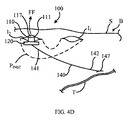
[1057] 図4Dに示すように、次いで接続口110の近位部111は、矢印FFで示すように皮膚Sを貫通して配置される。このようにして、接続口110は、固定装置120が身体B内の皮下に配置され、近位部111の端子表面117が身体Bの外側の領域から利用可能になるように、身体Bの中に配置される。それに応じて、前述のように固定装置120は、身体Bの中で接続口110の位置を保つことができるようになる。言い換えれば、その場合、接続口110の近位部111は皮膚Sを貫通して配置され、第2の切開部I2を画定する。
[1057] As shown in FIG. 4D, the
[1058] 図4Aでは、刺激システム100を2つの挿入路(すなわちPINS1およびPINS2)を介して挿入されるものとして示し説明しているが、他の実施形態では、刺激システム100を単一の挿入路を介して挿入することができる。例えばいくつかの実施形態では、接続口110の遠位端112を、挿入前に電気部材140の近位端部141に結合することが可能であり、次いでその組立体を単一の挿入路を介して挿入することができる。接続口110の遠位端112は、任意の適切な手段によって電気部材140の近位端部141に結合することができる。例えばいくつかの実施形態では、接続口110の遠位端112を、接続接着剤、磁気結合、溶接、はんだ付けおよび/または圧着によって、電気部材140の近位端部141に結合することができる。
[1058] Although FIG. 4A illustrates and describes the
[1059] 刺激システム100を、身体Bの中に経皮的に配置される1つの接続口110を有するものとして示し説明しているが、いくつかの実施形態において、刺激システムは、身体の中に経皮的に配置される複数の接続口を有することができる。さらに他の実施形態において、刺激システムは、身体の中に経皮的に配置される1つまたは複数の接続口、および身体の表面上に配置される1つまたは複数の表面電極を有することができる。さらに他の実施形態において、接続口は複数の別個の導電路を有することがきる。
[1059] Although the
[1060] 例えば図5は、身体Bの中に配置された、本発明の実施形態による刺激システム300の概略図である。刺激システム300は、身体Bの外側に配置された電気刺激装置330、身体Bの中に配置された電気部材340、接続口310および表面電極335を含む。接続口310は陰電極として働くことが可能であり、また先に示し説明した接続口110と同様である。接続口310は、接続口310の固定装置320が皮下に配置され、身体Bの中で接続口310の位置を保つように、身体Bの中に配置される。接続口310は、接続線332によって電気刺激装置330に電気的に結合される。接続口310は電気部材340に(例えば流電結合によって)電気的に結合され、かつ電気部材340から間隔をおいて配置される。
[1060] For example, FIG. 5 is a schematic diagram of a
[1061] 前述のように電気部材340は、近位端部341および遠位端部342を有し、当該電気部材340する導電路を画定する。電気部材340の近位端部341は、接続口310から間隔をおいて配置され、かつ接続口310に動作可能に結合される端子346を含む。電気部材340の遠位端部342は、身体の中で標的組織Tに隣接して配置される端子347を含む。このようにして、例えば電流などの電気信号を、接続口310を介して電気刺激装置330から身体Bの中の標的組織T(例えば神経組織)へ伝達することができる。さらに、皮膚Sを含まない電気経路を介して、電気刺激装置330から身体Bの中の標的組織Tへ電流を伝達することができる。
[1061] As described above, the electrical member 340 has a
[1062] 表面電極335は陽電極として働くことが可能であり、皮膚Sの表面上に配置される。皮膚Sの表面上での表面電極335の位置は、例えば導電性のゲル、接着剤、湿式の電極、嵌め込み式の覆いなどの適切な手段によって保つことができる。表面電極335は、接続線333によって電気刺激装置330に電気的に結合される。表面電極335は、身体Bへ電気信号を伝える、かつ/または身体Bから電気信号を受け取るための任意の適切な電極とすることができる。例えばいくつかの実施形態では、表面電極335をゲル電極とすることができる。他の実施形態では、表面電極335を、電気リードを有する可撓性のディスク型電極とすることができる。同様に表面電極335を、例えば導電性電解質のゲル、導電性ゴム、導電性プラスチック、金属メッシュ、金属板、金属化されたゴムおよび/またはプラスチックなどの任意の適切な材料から構成することができる。
[1062] The
[1063] 使用時に電気刺激装置330は、治療刺激に適した特性を有する電流を発生させることができる。電流は、接続口310、電気部材340、およびそれらの間の皮下の体組織を含む身体Bの中の(図5に破線で示す)第1の刺激経路PSTIM1に沿って流れる。このようにして、電流の少なくとも一部を電気刺激装置330から標的組織Tへ伝達することができる。次いでその一部の電流が、皮下の体組織および皮膚を含む身体Bの中の(図5に破線で示す)第2の刺激経路PSTIM2を介して表面電極335に戻る。
[1063] In use, the
[1064] 刺激システム300を、1つの陰電極(すなわち接続口310)および1つの陽電極(すなわち表面電極335)を含むものとして示し説明しているが、いくつかの実施形態において、刺激システムは、陰電極としても陽電極としても機能することが可能な、少なくとも1つの電極および/または接続口を含むことができる。他の実施形態において、刺激システムは、複数対の陰電極および/または複数の陽電極として機能するように構成された、複数の表面電極および/または接続口を含むことができる。このように、本発明の実施形態による刺激システムは、2つ以上の刺激経路を介して電流を身体の中へ伝達することができる。
[1064] Although the
[1065] さらに先に示し説明した刺激システムは、完全に身体の中に配置された電気部材(例えば受動的な電気導体、電気装置など)を含むが、いくつかの実施形態では、刺激システムに完全に身体の中に配置された電気部材がなくてもよい。例えばいくつかの実施形態において、刺激システムは、先に示し説明したタイプの電気刺激装置および接続口を含むことができる。そうした刺激システムでは、皮膚を含まず皮下の体組織を含む刺激経路を介して、電気信号を電気刺激装置から標的組織へ伝達することができる。 [1065] Although the stimulation systems shown and described further include electrical components (eg, passive electrical conductors, electrical devices, etc.) that are placed entirely within the body, in some embodiments, the stimulation system includes There may be no electrical components placed entirely within the body. For example, in some embodiments, the stimulation system can include an electrical stimulation device and connection of the type shown and described above. In such a stimulation system, an electrical signal can be transmitted from the electrical stimulator to the target tissue via a stimulation pathway that does not include skin but includes subcutaneous body tissue.
[1066] 例えば図6は、身体Bの中に配置された、本発明の実施形態による刺激システム400の概略図である。刺激システムは、身体Bの外側に配置された電気刺激装置430、4つの接続口410A〜410Dおよび4つの表面電極435A〜435Dを含む。接続口410A〜410Dは、先に示し説明した接続口と同様であり、一連の接続線432によって電気刺激装置430に電気的に結合される。表面電極435A〜435Dは、先に示し説明した接続口と同様であり、一連の接続線433によって電気刺激装置430に電気的に結合される。いくつかの実施形態において、刺激システム400は、接続口410A〜410Dおよび/または表面電極435A〜435Dの少なくとも第1の対を電気刺激装置430に電気的に結合すると同時に、接続口410A〜410Dおよび/または表面電極435A〜435Dの少なくとも第2の対を電気的に隔離することが可能になるように、マルチプレクサ(図7には示さず)を含むことができる。このようにして、以下に示すように、接続口410A〜410Dおよび表面電極435A〜435Dの配列を用いて、身体Bの中に複数の異なる刺激経路を画定することができる。さらにマルチプレクサは、接続口410A〜410Dおよび/または表面電極435A〜435Dを電気的に結合して、双極刺激または単極刺激を送達するように構成することができる。
[1066] For example, FIG. 6 is a schematic diagram of a
[1067] 例えば刺激システム400を、電気刺激装置430が第1の接続口410Aおよび第2の接続口410Bに電気的に結合される第1の構成として配置することができる。前述のように電気刺激装置430は、治療刺激に適した特性を有する電流を発生させる。電流は、電気刺激装置430から第1の接続口410Aまで流れることができる。次いで、電流を身体Bの中で、第2の接続口410Bで終わる第1の刺激経路PSTIM1を介して伝達することができる。このようにして、電流を電気刺激装置430から、例えば第1の末梢神経PN1を含むことができる第1の標的組織T1へ伝達することが可能になる。
[1067] For example, the
[1068] 図6に示すように、刺激システム400を、電気刺激装置430が第2の接続口410Bおよび第2の表面電極435Bに電気的に結合される第2の構成として配置することができる。電気刺激装置430からの電流は、電気刺激装置430から第2の接続口410Bまで流れることができる。次いで、電流を身体Bの中で、第2の表面電極435Bで終わる第2の刺激経路PSTIM2を介して伝達することができる。このようにして、電流を電気刺激装置430から、例えば第2の末梢神経PN2を含むことができる第2の標的組織T2へ伝達することが可能になる。
[1068] As shown in FIG. 6, the
[1069] 同様に刺激システム400を、電気刺激装置430が第3の接続口410Cおよび第4の接続口410Dに電気的に結合される第3の構成として配置することができる。電気刺激装置430からの電流は、電気刺激装置430から第3の接続口410Cまで流れることができる。次いで、電流を身体Bの中で、第4の接続口410Dで終わる第3の刺激経路PSTIM3を介して伝達することができる。このようにして、電流を電気刺激装置430から、例えば第3の末梢神経PN3を含むことができる第3の標的組織T3へ伝達することが可能になる。
[1069] Similarly, the
[1070] 同様に刺激システム400を、電気刺激装置430が第3の接続口410Cおよび第4の表面電極435Dに電気的に結合される第4の構成として配置することができる。電気刺激装置430からの電流は、電気刺激装置430から第3の接続口410Cまで流れることができる。次いで、電流を身体Bの中で、第4の表面電極435Dで終わる第4の刺激経路PSTIM4を介して伝達することができる。このようにして、電流を電気刺激装置430から、例えば第4の末梢神経PN4を含むことができる第4の標的組織T4へ伝達することが可能になる。
[1070] Similarly, the
[1071] 同様の形で、電流(単極または双極)を身体Bの中で接続口410A〜410Bの任意の組み合わせへ伝達するように、表面電極435A〜435Dの任意の組み合わせを選択することができる。同様に、電流を身体Bの中で伝達して1つまたは複数の標的組織T1〜T4を刺激するように、接続口410A〜410Dの任意の組み合わせを選択することができる。言い換えれば、標的体組織の特定領域を刺激するために、接続口410A〜410Dおよび/または表面電極435A〜435Dの配列を選択的に用いることができる。
[1071] Selecting any combination of surface electrodes 435A-435D to transfer current (monopolar or bipolar) in body B to any combination of
[1072] 接続口410A〜410Dおよび/または表面電極435A〜435Dの選択は、接続口410A〜410Dおよび/または表面電極435A〜435Dの各対を電気刺激装置430に繰り返し電気的に結合し、患者の応答を測定して望ましい選択を決定することによって、手動で実施することができる。あるいはいくつかの実施形態において、刺激システム400は、接続口410A〜410Dおよび/または表面電極435A〜435Dを電気刺激装置430に対して自動的に選択し、電気的に結合するように構成された処理装置を含むことができる。例えばいくつかの実施形態において、刺激システム400は、接続口410A〜410Dおよび/または表面電極435A〜435Dの様々な組み合わせの間のインピーダンスに基づき、接続口410A〜410Dおよび/または表面電極435A〜435Dを電気刺激装置430に対して自動的に選択する、かつ/または電気的に結合するように構成された処理装置を含むことができる。他の実施形態において、刺激システム400は、測定された患者からの応答(例えば、筋肉の応答および/または言葉による応答)、および/または使用者による直接入力(例えば患者の応答に依存しない入力)に基づき、接続口410A〜410Dおよび/または表面電極435A〜435を自動的に選択する、かつ/または電気的に結合するように構成された処理装置を含むことができる。
[1072] Selection of
[1073] これまで刺激システムを、電流を伝達して身体の中の標的組織を刺激するように構成されたものとして示し説明しているが、いくつかの実施形態では、刺激システムを、電気信号を身体の中に配置された電気装置へ伝達するように構成することができる。例えば図7は、身体Bの中に配置された、本発明の実施形態による刺激システム500の概略図である。刺激システム500は、身体Bの外側に配置された電気刺激装置530、身体Bの中に配置された電気部材540、身体の中に配置された電気装置550、および接続口510を含む。接続口510は、先に示し説明した接続口と同様であり、接続口510の遠位部512が身体Bの中で電気部材540に隣接して皮下に配置されるように、身体Bの中に配置される。接続口510の近位部511は、接続線532によって電気刺激装置530に電気的に結合される。
[1073] While the stimulation system has previously been shown and described as being configured to transmit current to stimulate a target tissue in the body, in some embodiments, the stimulation system is an electrical signal. Can be transmitted to an electrical device disposed within the body. For example, FIG. 7 is a schematic diagram of a
[1074] 前述のように電気部材540は、近位端部541および遠位端部542を有し、当該電気部材540する導電路を画定する。近位端部541は、接続口510から間隔をおいて配置され、かつ(例えば流電結合によって)接続口510に動作可能に結合される。電気部材540の遠位端部542は、電気装置550に電気的に結合される。このようにして、電気信号を、接続口510を介して電気刺激装置530から身体Bの中の電気装置550へ伝達することができる。さらに電気信号を、皮膚Sを含まない電気経路を介して、電気刺激装置530から電気装置550へ伝達することができる。
[1074] As described above, the electrical member 540 has a
[1075] 電気装置550は、電流、および/または電気信号を受け取る任意の電気装置によって動力を供給される任意の電気装置とすることができる。例えばいくつかの実施形態では、電気装置550を、身体内のパラメータを入手するために身体Bの中に移植されたセンサとすることができる。そうしたセンサには、例えば神経電図(ENG)センサ、筋電図(EMG)センサ、心電図(ECG)センサ、温度センサ、圧力センサ、pHセンサ、傾斜センサ、加速度計、ジャイロスコープ、変位センサおよび/またはインピーダンスセンサを含むことができる。他の実施形態では、電気装置550を、例えば増幅器、フィルタ、高電圧/定電流発生装置、電気スイッチ、電源、電池(小型の充電式電池を含む)、電池充電回路、処理装置、周波数シフタ、過剰刺激の保護回路および/または通信モジュール(有線または無線)など、身体Bの中に移植された電気回路の一部とすることができる。
[1075] The
[1076] 使用時に電気刺激装置530は、電気装置550に関連付けられた特徴を有する電気信号(例えば電流)を発生させる。電気信号は、接続口510、皮膚Sを含まない電気経路を介して、電気刺激装置530から身体Bの中の電気装置550へ伝達することができる。それに応じて、電気信号が皮膚Sを通過しないため、電気信号は皮下の体組織に害を及ぼさない任意の振幅および/または周波数を有することができる。
[1076] In use, the
[1077] 刺激システム500を、電気部材540の遠位端部542に結合された単一の電気装置550を含むものとして示しているが、他の実施形態では、電気装置550を電気部材540の任意の部分に結合することができる。さらに他の実施形態では、刺激システムは複数の電気装置550および/または複数の電気部材540を含むことができる。例えば図8は、身体Bの中に配置された、本発明の実施形態による刺激システム600の概略図である。刺激システム600は、身体Bの外側に配置された電気刺激装置630、それぞれが身体Bの中に配置された第1の電気部材640Aおよび第2の電気部材640B、それぞれが身体Bの中に配置された第1の電気装置650Aおよび第2の電気装置650B、接続口610ならびに表面電極635を含む。接続口610は、先に示し説明した接続口と同様であり、接続口610の遠位部612が身体Bの中で電気部材640に隣接して皮下に配置されるように、身体Bの中に配置される。接続口610は、接続線632によって電気刺激装置630に電気的に結合される。
[1077] Although the
[1078] 表面電極635は皮膚Sの表面上に配置され、接続線633によって電気刺激装置630に電気的に結合される。前述のように表面電極635は、身体Bへ電気信号を伝える、かつ/または身体Bから電気信号を受け取るための任意の適切な電極とすることができる。
[1078] The
[1079] 第1の電気部材640Aは、近位端部641A、遠位端部642Aおよび中央部649Aを有し、当該第1の電気部材640Aする導電路を画定する。第1の電気部材640Aの近位端部641Aは、接続口610に電気的に結合される。第1の電気部材640Aの中央部649Aは、第1の電気装置650Aに電気的に結合される。第1の電気部材640Aの遠位端部642Aは、身体の中で標的組織Tに隣接して配置される。このようにして、電気信号を、接続口610を介して電気刺激装置630から第1の電気装置650Aへ、次いで標的組織Tへ伝達することができる。言い換えれば、この配置によって、電気信号を順次、第1の電気装置650Aおよび標的組織Tへ伝達することが可能になる。前述のように、電気信号を、体組織を含む刺激経路PSTIMを介して表面電極635に戻すことができる。
[1079] The first
[1080] 第2の電気部材640Bは、近位端部641Bおよび遠位端部642Bを有し、当該第2の電気部材640Bする導電路を画定する。第2の電気部材640Bの近位端部641Bは、第1の電気部材640Aと並行して接続口610に電気的に結合される。第2の電気部材640Bの遠位端部642Bは、第2の電気装置650Bに電気的に結合される。このように標的組織Tの刺激と並行して、電気信号を、電気刺激装置630から第2の電気装置650Bへ伝達することができる。
[1080] The second
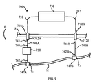
[1081] これまで刺激システムを、電気信号を標的組織および/または移植された電気装置へ伝達するものとして示し説明しているが、他の実施形態では、医療システムが、標的組織および/または移植された電気装置からの電気信号を受け取るようにすることができる。そうした電気信号には、例えば身体内の神経組織からの単極性信号および両極性信号(例えば神経電図、すなわちENG信号)を含むことができる。例えば図9は、身体Bの中に配置された、本発明の実施形態による医療システム700の概略図である。医療システム700は、身体Bの外側に配置された電気装置730、第1の電気部材740Aおよび第2の電気部材740B、身体の内側に配置された電気装置750、第1の接続口710Aおよび第2の接続口710Bを含む。
[1081] While the stimulation system has been shown and described so far as transmitting electrical signals to the target tissue and / or implanted electrical device, in other embodiments, the medical system may be configured to target tissue and / or implantation. It is possible to receive an electrical signal from a connected electrical device. Such electrical signals can include, for example, unipolar signals and bipolar signals from neural tissue within the body (eg, electroencephalograms or ENG signals). For example, FIG. 9 is a schematic diagram of a
[1082] 第1の接続口710Aは、先に示し説明した接続口と同様であり、第1の接続口710Aの遠位部712Aが身体Bの中で第1の電気部材740Aに隣接して皮下に配置されるように、身体Bの中に配置される。第1の接続口710Aは、接続線732によって電気装置730に電気的に結合される。同様に第2の接続口710Bは、第2の接続口710Bの遠位部712Bが身体Bの中で第2の電気部材740Bに隣接して皮下に配置されるように、身体Bの中に配置される。第2の接続口710Bは、接続線732によって電気装置730に電気的に結合される。
[1082] The
[1083] 身体Bの外側に配置される電気装置730は、電気信号を受け取る、かつ/または処理するように構成された任意の電気装置とすることができる。いくつかの実施形態では、電気装置を信号処理装置とすることができる。他の実施形態では、電気装置を、例えばデータロガー、ストリップチャートレコーダなどの電気的なデータ記録装置とすることができる。身体Bの内側に配置される電気装置750は、例えばセンサ、増幅器、フィルタ、通信モジュールなど、身体の中に移植されるように構成された任意の電気装置とすることができる。
[1083] The
[1084] 第1の電気部材740Aは、近位端部741A、遠位端部742Aおよび中央部749Aを有し、当該第1の電気部材740Aする導電路を画定する。第1の電気部材740Aの近位端部741Aは、第1の接続口710Aに電気的に結合される。第1の電気部材740Aの中央部749Aは、身体Bの中に配置された電気装置750に電気的に結合される。第1の電気部材740Aの遠位端部742Aは、身体Bの中で第1の標的組織T1に隣接して、または第1の標的組織T1のまわりに配置される端子表面747A(例えば電気ピックアップ)を含む。第1の標的組織T1は、例えば神経N上の第1の位置とすることができる。
[1084] The first
[1085] 第2の電気部材740Bは、近位端部741Bおよび遠位端部742Bを有し、当該第2の電気部材740Bする導電路を画定する。第2の電気部材740Bの近位端部741Bは、第2の接続口710Bに電気的に結合される。第2の電気部材740Bの遠位端部742Bは、身体Bの中で第2の標的組織T2に隣接して配置される端子表面747B(例えば電気ピックアップ)を含む。第2の標的組織T2は、例えば第1の位置から間隔をおいて配置された、神経N上の第2の位置とすることができる。
[1085] The second
[1086] 使用時に端子表面747Aおよび747Bはそれぞれ、神経Nによって生成された第1の電気信号および第2の電気信号を受け取ることができる。第1の電気信号は、電気部材740Aを介して端子表面747Aから身体Bの中に配置された電気装置750へ伝達することができる。いくつかの実施形態において、電気装置750は、例えば信号を増幅し、信号を処理することなどによって第1の電気信号を処理することができる。このようにして、第1の電気信号が身体Bの外側の電気装置730へ伝達される前に、第1の電気信号の質を改善することができる。次いで、結果として生じる第1の電気信号を、第1の接続口710Aを介して身体Bの外側に配置された電気装置730へ伝達することができる。同様に第2の電気信号を、第2の接続口710Bを介して、端子表面747Bから身体Bの外側に配置された電気装置730へ伝達することができる。
[1086] In use,
[1087] いくつかの実施形態では、先に示し説明した接続口を、生体組織(例えば真皮および/または表皮)と結合してシールを形成する生体適合材料から構成することができる。例えば図10は、身体Bの中に経皮的に配置された、本発明の実施形態による接続口810の概略図である。接続口810は、スタッド816および固定装置820を含み、近位部811および遠位部812を有する。近位部811は接続表面817を含む。遠位部812は端子表面827を含む。スタッド816は、第1の電気伝導率を有する第1の材料から構成された外側部分828、および第1の材料の電気伝導率より大きい第2の電気伝導率を有する第2の材料から構成された内側部分829を含む。このようにして、内側部分829は、接続表面817と端子表面827の間に導電路826を画定する。
[1087] In some embodiments, the connection port shown and described above can be composed of a biocompatible material that forms a seal with living tissue (eg, dermis and / or epidermis). For example, FIG. 10 is a schematic view of a connection port 810 according to an embodiment of the present invention placed percutaneously in the body B. The connection port 810 includes a
[1088] 前述のように固定装置820は、接続口810の遠位部812に配置され、かつ身体Bの皮膚Sの下に配置される。固定装置820はスタッド816から外側へ延び、接続口810を身体Bの中の皮下位置に固定する。
[1088] As described above, the fixation device 820 is disposed at the distal portion 812 of the connection port 810 and below the skin S of the body B. The fixation device 820 extends outward from the
[1089] 接続口810の外側表面814の少なくとも一部は、スタッド816および/または固定装置820の外側表面814のまわりで柔らかい体組織が内部成長するのを促進するように構成された、繊維状および/または多孔性の層815で被覆される。繊維状および/または多孔性の層815は外側表面814の一部のまわりに配置され、接続口810が移植されたとき、繊維状および/または多孔性の層815は皮膚Sの真皮Dの中に配置されるようになる。このようにして、繊維状および/または多孔性の層815は、(図10に矢印CCで示すように)表皮Eの下方への成長を妨げ、かつ/また真皮Dの接続口810への結合を促進することができる。言い換えれば、繊維状および/または多孔性の層815によって、表皮細胞の増殖によって皮膚Sの切開部を閉じる、かつ/または接続口810を押し出す身体の自然の性向を制限することができる。
[1089] At least a portion of the outer surface 814 of the connection port 810 is fibrous, configured to promote soft body tissue ingrowth around the outer surface 814 of the
[1090] 繊維状および/または多孔性の層815は、任意の適切な材料から構成することができる。いくつかの実施形態において、繊維状および/または多孔性の層815は、例えばチタン、無光沢のチタン、ニチノール、銀またはステンレス鋼などの1つまたは複数の生体適合性の金属材料を含むことができる。他の実施形態において、繊維状および/または多孔性の層815は、例えばDacron(商標)、Teflon(商標)、 ポリオレフィン類、ナイロン、シリコーン、可撓性のあるポリウレタン、ポリプロピレン、ガラス状の炭素繊維、ポリテトラフルオロエチレンなどの1つまたは複数の高分子材料を含むことができる。さらに他の実施形態において、繊維状および/または多孔性の層815は、細かい柱状構造(trabecularized)の炭素およびチタンのコーティングを含むことができる。さらに他の実施形態において、繊維状および/または多孔性の層815は抗菌剤を含むことができる。そうした薬剤を、繊維状および/または多孔性の層815、スタッド816ならびに/あるいは固定装置820の上にコートする、それらの中に移植する、かつ/または含浸させることができる。そうした薬剤には、例えば抗生物質、抗真菌剤、抗ウイルス剤、抗炎症剤および他の治癒剤(例えば、銀または銀のコーティング)を含むことができる。
[1090] The fibrous and / or
[1091] 先に示し説明した接続口110は、スタッド116から半径方向に延びる固定装置120を含むが、いくつかの実施形態において、固定装置120は、スタッド116に対して任意の適切な形および/または向きを有することができる。例えばいくつかの実施形態において、接続口は、鋭い縁部および/またはきつい凹面のない楕円形を有する固定装置を含むことができる。他の実施形態において、接続口は、身体内で接続口の位置を保つように構成された複数の表面を有する固定装置を含むことができる。そうした表面は、例えば身体内で接続口の位置を保つために、それぞれが皮膚および/または皮下組織の一部と係合および/または接触するように構成された、不連続な表面とすることができる。さらに他の実施形態において、接続口は、身体内で接続口の位置を協働して保つように構成された複数の部材を有する固定装置を含むことができる。
[1091] The
[1092] 図11は、身体Bの中に経皮的に配置された、本発明の実施形態による接続口910の正面図である。接続口910は、近位部911および遠位部912を有する。近位部911は接続表面917を含む。接続表面917は、皮膚Sの外側表面と実質的に平行になるように構成される。言い換えれば、接続表面917は、接続口910がそれを通して身体Bに経皮的に挿入される挿入路PINSの中心線CLに対して実質的に垂直である。
[1092] FIG. 11 is a front view of a
[1093] 遠位部912は固定装置920を含む。固定装置920は、皮膚Sの外側表面と実質的に平行な軸ACのまわりで円形を有する。言い換えれば、固定装置920は、挿入路PINSの中心線CLに実質的に垂直な軸のまわりで円形を有する。いくつかの実施形態では、例えば固定装置は軸ACのまわりで環状形を有する。図11は接続口910の正面図であるため、軸ACは点として示され、頁から延びることになる。固定装置920は開口部919を画定し、その一部が皮膚Sの下に配置される。このようにして、図11に示すように、固定装置920を電気部材940のまわりに配置することができる。前述のように電気部材940は、電気信号を接続口910から身体B内の組織および/または装置に伝達するための導電路を画定する、任意の移植可能な部材とすることができる。
[1093] The
[1094] 図12は、身体Bの中に経皮的に配置された、本発明の実施形態による接続口1010の正面図である。接続口1010は、近位部1011および遠位部1012を有する。近位部1011は接続表面1017を含む。遠位部1012は、固定装置1020および拡張器1018を含む。固定装置1020は、図11を参照して前述した固定装置920と同様であり、皮膚Sの外側表面と実質的に平行な軸ACのまわりで円形を有する。拡張器1018は、接続口1010が身体に挿入されるとき、体組織を移動させるように構成されたテーパ部1024を有する。
[1094] FIG. 12 is a front view of a
[1095] 先に示し説明した接続口910および1010は、連続的な円形を有する固定装置を含むが、他の実施形態において、接続口は、不連続な円形を画定する複数の部材を有する固定装置を含むことができる。例えば図13は、身体Bの中に経皮的に配置された、本発明の実施形態による接続口1110の正面図である。接続口1110は、近位部1111および遠位部1112を有する。近位部1111は接続表面1117を含む。遠位部1112は、第1の部材1121および第2の部材1122を有する固定装置1120を含む。第1の部材1121および第2の部材1122は協働して、皮膚Sの外側表面と実質的に平行な軸ACのまわりで円形を画定する。しかし、第1の部材1121および第2の部材1122の遠位端は間隔をおいて配置され、円形は不連続である。
[1095] The
[1096] これまで固定装置を、接続口の他の部分に対して定位置にあるものとして示し説明しているが、いくつかの実施形態では、固定装置の少なくとも一部が接続口の他の部分に対して移動することができる。例えばいくつかの実施形態において、接続口は、第1の部材、および第1の部材に対して移動可能な第2の部材を有する固定装置を含むことができる。このようにして、第2の部材が第1の部材に対して移動し、固定装置を第1の構成(例えば挿入用の構成)と第2の構成(例えば固定用の構成)の間で移動させることが可能になる。他の実施形態において、接続口は、接続口の近位端に対して移動可能な、一体として構成された固定装置を含むことができる。このようにして、接続口が第1の構成と第2の構成の間で移動することが可能になる。さらに他の実施形態において、接続口は、移動可能な固定装置、および所定の構成(例えば、挿入用の構成または固定用の構成)で移動可能な固定装置を偏倚させるように構成された偏倚部材を含むことができる。 [1096] While the fixing device has been shown and described herein as being in place relative to other portions of the connection port, in some embodiments, at least a portion of the fixation device is connected to the other portion of the connection port. Can move relative to the part. For example, in some embodiments, the connection port can include a fixation device having a first member and a second member movable relative to the first member. In this way, the second member moves relative to the first member, and the fixing device moves between the first configuration (for example, the configuration for insertion) and the second configuration (for example, the configuration for fixing). It becomes possible to make it. In other embodiments, the connection port can include an integrally configured fixation device that is movable relative to the proximal end of the connection port. In this way, the connection port can move between the first configuration and the second configuration. In yet another embodiment, the connection port is a biasing member configured to bias the movable fixing device and the fixing device movable in a predetermined configuration (eg, an insertion configuration or a fixing configuration). Can be included.
[1097] これまで接続線を、接続口の近位部に機械的に結合されるものとして示し説明しているが、いくつかの実施形態では、介在する構造体を用いて、接続線と接続口を機械的および/または電気的に結合することができる。例えば図14は、本発明の実施形態による刺激システム1200の一部を示している。刺激システム1200は、少なくとも1つの接続口1210、表面電極1235、接続線1232、および身体Bの中に移植された電気部材1240を含む。接続口1210は、先に示し説明した接続口と同様であり、近位部1211および遠位部1212を含む。前述のように接続口1210は、それを貫通し、皮膚Sの電気インピーダンスより小さい電気インピーダンスを有する導電路を画定する。
[1097] Although the connection line has been shown and described above as being mechanically coupled to the proximal portion of the connection port, in some embodiments, an intervening structure is used to connect the connection line and the connection line. The mouth can be mechanically and / or electrically coupled. For example, FIG. 14 illustrates a portion of a
[1098] 接続線1232は、例えば導電性電解質のゲル電極とすることができる表面電極1235によって、接続口1210の近位部1211に機械的および電気的に結合される。それに応じて、接続線1232、表面電極1235、接続口1210および皮下組織の一部を含む刺激経路PSTIMを介して、身体の外側の領域と電気部材1240との間で電気信号を伝達することができる。表面電極1235の一部が皮膚Sと接触しているため、表面電極1235によって若干量の電気信号(例えば逃げ電流(escape current))が、皮膚Sを含む逃げ経路PESCを介して身体Bの中へ伝達される可能性がある。しかし、接続口1210によって画定される導電路が皮膚Sの電気インピーダンスより小さい電気インピーダンスを有するため、逃げ経路を介して伝達される電気信号の大きさは微小である。
[1098] The
[1099] いくつかの実施形態において、接続線は、皮膚Sに直接接触していないコネクタを介して、接続口に機械的および/または電気的に結合することができる。このようにして、逃げ電流をさらに最小化する、かつ/またはなくすことができる。いくつかの実施形態では、コネクタを、例えばスナップ式コネクタ、わに口クリップ、ねじ式コネクタ、摺動式コネクタなどの取り外し可能なコネクタとすることができる。他の実施形態では、コネクタを、例えばはんだ付けされたコネクタ、溶接されたコネクタ、圧着されたコネクタなど、取り外しできないものとすることができる。 [1099] In some embodiments, the connection line can be mechanically and / or electrically coupled to the connection port via a connector that is not in direct contact with the skin S. In this way, the escape current can be further minimized and / or eliminated. In some embodiments, the connector can be a removable connector, such as a snap connector, an alligator clip, a screw connector, a sliding connector, and the like. In other embodiments, the connector may be non-removable, such as a soldered connector, a welded connector, a crimped connector, and the like.
[1100] 例えば図15は、本発明の実施形態による刺激システム1300の一部を示している。刺激システム1300は、少なくとも1つの接続口1310、コネクタ1360および接続線1332を含む。接続口1310は、近位部1311および遠位部1312を含む。近位部1311は突起部1317を含む。遠位部1312は、端子表面1327および固定装置1320を含む。前述のように固定装置1320は、身体Bの皮膚Sの下に配置され、接続口1310を身体Bの中の皮下位置に固定する。
[1100] For example, FIG. 15 illustrates a portion of a
[1101] コネクタ1360は、近位端1367および遠位端1368を有し、第1の電気伝導率を有する第1の材料から構成される外側部分1363、および第1の材料の電気伝導率より大きい第2の電気伝導率を有する第2の材料から構成される内側部分1362を含む。このように内側部分1362は、近位端1367と遠位端1368の間にコネクタを貫通する導電路を画定する。しかし、いくつかの実施形態では、コネクタ1360を単一の材料から構成することができる。
[1101] The
[1102] 接続線1332は、コネクタ1360の近位端1367に結合される。コネクタ1360の遠位端1368は、接続口1310の突起部1317を嵌合して受け入れるように構成された開口部1361を画定する。このようにして、コネクタ1360を接続口1310に対する所定の位置で、取り外せるように接続口1310に結合する(例えばスナップ止めする)ことができる。
[1102] The connecting
[1103] 接続口1310を、皮膚Sの表面より上に延び、凸形をした突起部1317を有するものとして示しているが、他の実施形態では、接続口は、身体の外側の領域から利用可能な任意の適切な端子表面を含むことができる。例えば図16は、本発明の実施形態による接続口1410を示している。接続口1410は、近位部1411および遠位部1412を含む。近位部1411は、端子表面1417の少なくとも一部が皮膚Sの外側表面より下に配置されるように、凹形を有する端子表面1417を含む。端子表面1417は、身体Bの外側の領域から利用することができる。前述のように遠位部1412は、接続口1410を身体Bの中の皮下位置に固定するために、身体Bの皮膚Sの下に配置された固定装置1420を含む。
[1103] Although the
[1104] これまで本発明の様々な実施形態について説明してきたが、それらは例として示したものにすぎず、限定的なものではないことを理解すべきである。前述の方法は、特定の順序で行われる特定の事象を示しているが、特定の事象の順序を変更することができる。さらに特定の事象は、前述のように順次実施するだけではなく、可能であるときには並行処理として同時に実施することができる。したがって、本発明の広さおよび範囲は、前述の実施形態のいずれによっても限定されるべきではない。本発明を、特にその特定の実施形態を参照して示し説明してきたが、形および細部に様々な変更を加えることが可能であることが理解されるであろう。 [1104] While various embodiments of the present invention have been described above, it should be understood that they have been presented by way of example only and not limitation. Although the foregoing method shows specific events occurring in a specific order, the order of specific events can be changed. Furthermore, specific events can be performed not only sequentially as described above, but also simultaneously as parallel processing when possible. Accordingly, the breadth and scope of the present invention should not be limited by any of the above-described embodiments. Although the present invention has been shown and described with particular reference to specific embodiments thereof, it will be understood that various modifications can be made in form and detail.
[1105] 例えば先に示し説明した刺激システムは、完全に身体の中に配置された電気部材(例えば受動的な電気導体、電気装置など)を含むが、いくつかの実施形態では、刺激システムに完全に身体の中に配置された電気部材がなくてもよい。例えばいくつかの実施形態において、刺激システムは、先に示し説明したタイプの電気刺激装置および接続口を含むことができる。そうした刺激システムでは、皮膚を含まず皮下の体組織を含む刺激経路を介して、電流を電気刺激装置から標的組織へ伝達することができる。 [1105] For example, the stimulation system shown and described above includes electrical components (eg, passive electrical conductors, electrical devices, etc.) that are placed entirely within the body, but in some embodiments, the stimulation system includes There may be no electrical components placed entirely within the body. For example, in some embodiments, the stimulation system can include an electrical stimulation device and connection of the type shown and described above. In such stimulation systems, current can be transmitted from the electrical stimulator to the target tissue via a stimulation pathway that does not include skin but includes subcutaneous body tissue.
[1106] これまで接続口を、皮膚の外側表面と同じ高さ、またはそれより上に位置するように構成された端子表面を有するものとして示し説明しているが、いくつかの実施形態において、接続口は、依然として身体の外側の領域から利用可能でありながら、皮膚の外側表面より下に位置するように構成された(すなわち窪んだ)端子表面を有することができる。さらに他の実施形態において、接続口は、端子表面の一部が皮膚の外側表面より上に配置され、かつ端子表面の一部が皮膚の外側表面より下に配置されるような非平面の端子表面を有することができる。 [1106] While the connection port has previously been shown and described as having a terminal surface configured to be at or above the outer surface of the skin, in some embodiments, The connection port may have a terminal surface that is configured (ie, recessed) to be located below the outer surface of the skin while still being available from an area outside the body. In yet another embodiment, the connection port is a non-planar terminal such that a portion of the terminal surface is disposed above the outer surface of the skin and a portion of the terminal surface is disposed below the outer surface of the skin. Can have a surface.
[1107] 様々な実施形態を、各構成要素の特定の特徴および/または組み合わせを有するものとして説明してきたが、適切な場合には、他の実施形態が、実施形態の任意のものからの任意の特徴および/または構成要素の組み合わせを有するようにすることが可能である。例えばいくつかの実施形態において、刺激システムは、先に示し説明したタイプの任意の接続口、ならびに/または外部の電気装置、内部の電気装置および/もしくは本明細書で示し説明した電気部材の任意の配置を含むことができる。例えばいくつかの実施形態において、刺激システムは、(図11〜13を参照して先に論じた)円形の固定装置および接続口の遠位部に接触した電気部材を有する、1つまたは複数の接続口を含むことができる。 [1107] Although various embodiments have been described as having specific features and / or combinations of components, other embodiments can be added from any of the embodiments, where appropriate. It is possible to have a combination of features and / or components. For example, in some embodiments, the stimulation system may include any connection port of the type shown and described above, and / or any external electrical device, internal electrical device, and / or any electrical member shown and described herein. Can be included. For example, in some embodiments, the stimulation system includes one or more of a circular fixation device (discussed above with reference to FIGS. 11-13) and an electrical member in contact with the distal portion of the connection port. A connection port can be included.
Claims (19)
完全に前記身体の中に配置されるように構成された電気部材と、
前記電気装置と前記電気部材の間で前記電気信号を伝達するように構成された接続口であって、該接続口の近位部が前記身体の外側に配置され、該接続口の遠位部が前記身体の中に配置される形で前記身体に経皮的に挿入されるように構成された接続口と、
を備えるシステムであって、
前記接続口の近位部が前記電気装置に動作可能に結合されるように構成され、前記接続口の遠位部が前記電気部材に動作可能に結合され、かつ前記電気部材から間隔をおいて配置されるように構成される、システム。 An electrical device configured to be disposed outside the body and configured to at least generate or receive electrical signals;
And electrical member configured to be disposed entirely within the body,
A connection port configured to transmit the electrical signal between the electrical device and the electrical member, wherein a proximal portion of the connection port is disposed outside the body, and a distal portion of the connection port A connection port configured to be percutaneously inserted into the body in a form disposed within the body;
A system comprising:
A proximal portion of the connection port is configured to be operably coupled to the electrical device, and a distal portion of the connection port is operably coupled to the electrical member and spaced from the electrical member. configured Ru, the system to be placed.
前記接続口が複数の別個の電気経路を含み、前記複数の電気経路からの各電気経路が前記複数の電極からの対応する電極と電気的に連絡するように構成される、請求項1に記載のシステム。 The electrical member is a passive electrical conductor, the distal end of the passive electrical conductor, viewed contains a plurality of electrodes configured to be placed adjacent the target tissue in the body,
The electrical connection of claim 1, wherein the connection includes a plurality of separate electrical paths, and each electrical path from the plurality of electrical paths is configured to be in electrical communication with a corresponding electrode from the plurality of electrodes. System.
前記身体の中に配置されるように構成された第2の電気部材と、 A second electrical member configured to be disposed within the body;
前記第1の電気部材と前記第2の電気部材の間で前記電気信号を伝達するように構成された接続口であって、該接続口の近位部が前記身体の外側の領域から利用でき、かつ、該接続口の遠位部が前記身体の中に配置される形で前記身体に経皮的に配置されるように構成された接続口と、 A connection port configured to transmit the electrical signal between the first electrical member and the second electrical member, wherein a proximal portion of the connection port is accessible from a region outside the body; And a connection port configured to be disposed percutaneously in the body such that a distal portion of the connection port is disposed in the body;
を備えるシステムであって、 A system comprising:
前記接続口の近位部が前記第1の電気部材に結合されるように構成され、前記接続口の遠位部が前記第2の電気部材に電気的に結合され、かつ前記第2の電気部材から間隔をおいて配置されるように構成される、システム。 A proximal portion of the connection port is configured to be coupled to the first electrical member, a distal portion of the connection port is electrically coupled to the second electrical member, and the second electrical member A system configured to be spaced from a member.
The connecting port includes an electrical pathway having an electrical impedance less than the electrical impedance of the skin, the system of claim 7.
前記接続口が、前記両極性の刺激信号を前記第2の電気部材に伝達するように構成された複数の別個の電気経路を含む、請求項7に記載のシステム。 The system of claim 7, wherein the connection includes a plurality of separate electrical paths configured to transmit the bipolar stimulus signal to the second electrical member.
前記接続口の遠位端が、前記身体の中に皮下的に配置されかつ前記身体内での前記接続口の移動を制限するように構成された固定装置を含む、請求項7に記載のシステム。 The system of claim 7, wherein a distal end of the connection port includes a fixation device disposed subcutaneously in the body and configured to limit movement of the connection port within the body. .
前記第2の電気部材が、第1の端子部、第2の端子部、およびそれらの間の導体を有する受動的な電気導体であり、前記第2の端子部が標的組織に隣接して配置されるように構成され、前記第1の端子部が、前記電気信号が前記導体および前記第2の端子部を介して前記標的組織に伝達されるように前記接続口の遠位部から前記電気信号を受け取るように構成される、請求項7に記載のシステム。 The second electrical member is a passive electrical conductor having a first terminal portion, a second terminal portion, and a conductor between them, and the second terminal portion is disposed adjacent to the target tissue. The first terminal portion is configured so that the electrical signal is transmitted from the distal portion of the connection port so that the electrical signal is transmitted to the target tissue via the conductor and the second terminal portion. The system of claim 7, wherein the system is configured to receive a signal.
Wherein a surface electrode Ru consists on the surface of the skin of the body, further comprising a surface configured electrodes to be coupled to the stimulator system of claim 12.
前記身体の中に配置されるように構成されたインプラントであって、第1の端子部、第2の端子部、およびそれらの間の導体を有し、前記第2の端子部が、前記電気刺激信号を標的組織に伝達するように構成される、インプラントと、 An implant configured to be disposed within the body, the implant having a first terminal portion, a second terminal portion, and a conductor therebetween, wherein the second terminal portion is the electrical terminal. An implant configured to transmit a stimulation signal to a target tissue;
接続口であって、該接続口の近位部が前記身体の外側の領域から利用でき、かつ、該接続口の遠位部が前記身体の中に配置される形で少なくとも部分的に前記身体の中に配置されるように構成された接続口と、 A connection port, wherein a proximal portion of the connection port is available from a region outside the body, and a distal portion of the connection port is at least partially disposed in the body. A connection port configured to be disposed within,
を備えるシステムであって、 A system comprising:
前記接続口の近位部が前記刺激装置に結合するように構成され、前記接続口の遠位部が前記インプラントの前記第1の端子部に電気的に結合され、かつ前記インプラントの前記第1の端子部から間隔を置いて配置されるように構成される、システム。 A proximal portion of the connection port is configured to couple to the stimulator, a distal portion of the connection port is electrically coupled to the first terminal portion of the implant, and the first portion of the implant A system configured to be spaced from a terminal portion of the system.
前記接続口が、前記電気刺激信号を前記インプラントに伝送するように構成された複数の別個の電気経路を含む、請求項14に記載のシステム。
Before SL includes a second terminal portion is a plurality of electrodes of the implant, each of the electrodes from the plurality of electrodes is configured to pre-Symbol electrical stimulation signal to transmit a portion of the target tissue,
The connecting port includes a plurality of separate electrical paths that are configured to transmit the pre-Symbol electrical stimulation signals to the implant system of claim 14.
前記接続口の遠位端が、前記身体の中に皮下的に配置されかつ前記身体内での前記接続口の移動を制限するように構成された固定装置を含む、請求項14に記載のシステム。 The system of claim 14, wherein a distal end of the connection port includes a fixation device disposed subcutaneously in the body and configured to limit movement of the connection port within the body. .
Applications Claiming Priority (5)
| Application Number | Priority Date | Filing Date | Title |
|---|---|---|---|
| US82837606P | 2006-10-05 | 2006-10-05 | |
| US60/828,376 | 2006-10-05 | ||
| US11/867,454 | 2007-10-04 | ||
| US11/867,454 US8483820B2 (en) | 2006-10-05 | 2007-10-04 | System and method for percutaneous delivery of electrical stimulation to a target body tissue |
| PCT/US2007/080564 WO2008043065A2 (en) | 2006-10-05 | 2007-10-05 | System and method for percutaneous delivery of electrical stimulation to a target body tissue |
Publications (3)
| Publication Number | Publication Date |
|---|---|
| JP2010505550A JP2010505550A (en) | 2010-02-25 |
| JP2010505550A5 JP2010505550A5 (en) | 2010-11-18 |
| JP5308339B2 true JP5308339B2 (en) | 2013-10-09 |
Family
ID=39269244
Family Applications (1)
| Application Number | Title | Priority Date | Filing Date |
|---|---|---|---|
| JP2009531624A Expired - Fee Related JP5308339B2 (en) | 2006-10-05 | 2007-10-05 | System and method for transdermal delivery of electrical stimulation to target body tissue |
Country Status (7)
| Country | Link |
|---|---|
| US (1) | US8483820B2 (en) |
| EP (1) | EP2097851B1 (en) |
| JP (1) | JP5308339B2 (en) |
| AT (1) | ATE547147T1 (en) |
| AU (1) | AU2007303034B2 (en) |
| CA (1) | CA2663030A1 (en) |
| WO (1) | WO2008043065A2 (en) |
Families Citing this family (24)
| Publication number | Priority date | Publication date | Assignee | Title |
|---|---|---|---|---|
| JP4879754B2 (en) | 2004-01-22 | 2012-02-22 | リハブトロニクス インコーポレーテッド | Method for carrying electrical current to body tissue via implanted non-active conductor |
| US20100016929A1 (en) * | 2004-01-22 | 2010-01-21 | Arthur Prochazka | Method and system for controlled nerve ablation |
| AU2006261666B2 (en) | 2005-06-28 | 2011-05-26 | Bioness Inc. | Improvements to an implant, system and method using implanted passive conductors for routing electrical current |
| US8738137B2 (en) | 2007-08-23 | 2014-05-27 | Bioness Inc. | System for transmitting electrical current to a bodily tissue |
| EP2180918B1 (en) * | 2007-08-23 | 2017-07-12 | Bioness Inc. | Electrodes with a power source and with connectors for coupling to an external stimulator |
| US9757554B2 (en) | 2007-08-23 | 2017-09-12 | Bioness Inc. | System for transmitting electrical current to a bodily tissue |
| JP4475343B2 (en) * | 2008-04-04 | 2010-06-09 | 村田機械株式会社 | E-mail gateway device |
| US20090326602A1 (en) * | 2008-06-27 | 2009-12-31 | Arkady Glukhovsky | Treatment of indications using electrical stimulation |
| EP2488249A4 (en) * | 2009-10-13 | 2014-01-01 | Incumed Llc | Neural stimulator with percutaneous connectivity |
| AU2010200485A1 (en) * | 2010-02-10 | 2011-08-25 | Cochlear Limited | Percutaneous implant |
| US9153900B2 (en) * | 2011-10-14 | 2015-10-06 | Biomet Manufacturing Corp. | Implantable subcutaneous electrical socket and percutaneous plug |
| CA2866025A1 (en) | 2013-10-03 | 2015-04-03 | Quiang Song | Sensor unit for a functional electrical stimulation (fes) orthotic system |
| CA2866028A1 (en) | 2013-10-03 | 2015-04-03 | Farsad Kiani | Electrical stimulation for a functional electrical stimulation system |
| US9375569B2 (en) | 2013-10-03 | 2016-06-28 | Ensilver Canada | Controller unit for a functional electrical stimulation (FES) orthotic system |
| WO2015061453A1 (en) | 2013-10-22 | 2015-04-30 | Msssachusetts Institute Of Technology | Peripheral neural interface via nerve regeneration to distal tissues |
| US9364657B2 (en) | 2014-10-31 | 2016-06-14 | Ensilver Canada | Cuff unit for a functional electrical stimulation system |
| JPWO2016092611A1 (en) * | 2014-12-08 | 2017-09-21 | オリンパス株式会社 | Nerve stimulator |
| DE102015104583A1 (en) | 2015-03-26 | 2016-09-29 | Georg-August-Universität Göttingen Stiftung Öffentlichen Rechts, Universitätsmedizin | Implantable device for forming a permanent skin passage |
| EP3302695B1 (en) * | 2015-06-03 | 2024-04-17 | Vomaris Innovations, Inc. | Devices for treating muscles |
| US11179251B2 (en) | 2016-01-08 | 2021-11-23 | Massachusetts Institute Of Technology | Method and system for providing proprioceptive feedback and functionality mitigating limb pathology |
| AU2018318977B2 (en) * | 2017-08-18 | 2024-02-29 | Innocon Medical Aps | System for electrical stimulation of nerves |
| EP3675715A4 (en) | 2017-08-31 | 2021-06-02 | The Regents Of The University Of Michigan | Sensing strategies for health assessment of osseointegrated prostheses |
| WO2020102498A1 (en) * | 2018-11-14 | 2020-05-22 | Cardiac Assist Holdings Llc | Chain mail surgical collar and method of percutaneous device stabilization therewith |
| WO2023130130A2 (en) * | 2022-01-02 | 2023-07-06 | Arkady Glukhovsky | Device and method for delivery of transcutaneous current |
Family Cites Families (121)
| Publication number | Priority date | Publication date | Assignee | Title |
|---|---|---|---|---|
| US669254A (en) * | 1900-06-13 | 1901-03-05 | Ideal Stopper Company | Bottle-sealing device. |
| US3204637A (en) * | 1963-02-07 | 1965-09-07 | Erich J Frank | Stimulating apparatus |
| US3426748A (en) * | 1965-11-23 | 1969-02-11 | Gen Electric | Stimulator analyzer and locater |
| US3835864A (en) * | 1970-09-21 | 1974-09-17 | Rasor Ass Inc | Intra-cardiac stimulator |
| US3774618A (en) * | 1972-07-03 | 1973-11-27 | Avery Labor Inc | Implantable nerve stimulation electrode |
| US3964470A (en) * | 1974-07-25 | 1976-06-22 | Medtronic, Inc. | Percutaneous intradermal electrical connection system and implant device |
| US4032860A (en) * | 1975-07-11 | 1977-06-28 | Leveen Harry H | Radio frequency power generator having adjustable stabilized output level and fail-safe control circuits |
| US3995644A (en) | 1975-09-16 | 1976-12-07 | The United States Of America As Represented By The Administrator Of The National Aeronautics And Space Administration | Percutaneous connector device |
| US4102344A (en) * | 1976-11-15 | 1978-07-25 | Mentor Corporation | Stimulator apparatus for internal body organ |
| JPS56122245A (en) * | 1980-02-29 | 1981-09-25 | Pilot Pen Co Ltd:The | Automatic control system for transmission or recording and transmission and reception |
| US4793353A (en) | 1981-06-30 | 1988-12-27 | Borkan William N | Non-invasive multiprogrammable tissue stimulator and method |
| US4419995A (en) | 1981-09-18 | 1983-12-13 | Hochmair Ingeborg | Single channel auditory stimulation system |
| US4417888A (en) * | 1982-03-15 | 1983-11-29 | Renal Systems, Inc. | Percutaneous implant |
| US4578063A (en) | 1984-09-14 | 1986-03-25 | W. L. Gore & Assoc., Inc. | Central venous catheter |
| JPH0661366B2 (en) | 1986-06-03 | 1994-08-17 | ザ・リ−ジエンツ・オブ・ザ・ユニバ−シテイ・オブ・カリフオルニア | Organ coordination and synchronous function controller in anatomical system |
| JPH01164373A (en) | 1987-12-22 | 1989-06-28 | Asahi Glass Co Ltd | Skin piercing terminal |
| SE465910B (en) * | 1988-01-28 | 1991-11-18 | Jan Axel Svensson | DEVICE FOR CONNECTING CATHETRES IN A SKIN REVIEW |
| US5080099A (en) * | 1988-08-26 | 1992-01-14 | Cardiotronics, Inc. | Multi-pad, multi-function electrode |
| US4987897A (en) * | 1989-09-18 | 1991-01-29 | Medtronic, Inc. | Body bus medical device communication system |
| US5056518A (en) | 1990-07-02 | 1991-10-15 | Electro-Biology, Inc. | Optimization of bone formation at cathodes |
| IL97701A (en) * | 1991-03-28 | 1995-06-29 | Univ Ben Gurion | Device for generating hand function |
| US5443065A (en) * | 1991-09-24 | 1995-08-22 | Angeion Corporation | Connector for medical device |
| EP0561068B1 (en) * | 1992-02-20 | 1999-03-03 | Neomedics, Inc. | Implantable bone growth stimulator |
| US5565005A (en) * | 1992-02-20 | 1996-10-15 | Amei Technologies Inc. | Implantable growth tissue stimulator and method operation |
| US5356428A (en) * | 1992-03-31 | 1994-10-18 | Cardiotronics, Inc. | Non-invasive, radiolucent electrode |
| US5441518A (en) * | 1993-07-22 | 1995-08-15 | Angeion Corporation | Implantable cardioverter defibrillator system having independently controllable electrode discharge pathway |
| US5325870A (en) * | 1992-12-16 | 1994-07-05 | Angeion Corporation | Multiplexed defibrillation electrode apparatus |
| WO1994029932A1 (en) * | 1993-06-07 | 1994-12-22 | Cochlear Pty. Ltd. | Percutaneous connector system |
| US5465715A (en) * | 1993-08-13 | 1995-11-14 | Ludlow Corporation | Positive locking biomedical electrode and connector system |
| GB9321086D0 (en) * | 1993-10-13 | 1993-12-01 | Univ Alberta | Hand stimulator |
| JPH07308392A (en) | 1994-03-25 | 1995-11-28 | Japan Steel Works Ltd:The | Treating apparatus for tinnitus aurium by electric stimulation |
| US5545191A (en) * | 1994-05-06 | 1996-08-13 | Alfred E. Mann Foundation For Scientific Research | Method for optimally positioning and securing the external unit of a transcutaneous transducer of the skin of a living body |
| US5571148A (en) * | 1994-08-10 | 1996-11-05 | Loeb; Gerald E. | Implantable multichannel stimulator |
| US5604976A (en) * | 1994-10-18 | 1997-02-25 | Pi Medical Corporation | Method of making percutaneous connector for multi-conductor electrical cables |
| US5591217A (en) * | 1995-01-04 | 1997-01-07 | Plexus, Inc. | Implantable stimulator with replenishable, high value capacitive power source and method therefor |
| BR9608465A (en) * | 1995-05-08 | 1998-12-29 | Massachusetts Inst Technology | Wireless communication system and computer system |
| US6076016A (en) * | 1995-10-19 | 2000-06-13 | Feierbach; Gary F. | Galvanic transdermal conduction communication system and method |
| US6051017A (en) * | 1996-02-20 | 2000-04-18 | Advanced Bionics Corporation | Implantable microstimulator and systems employing the same |
| CA2171067A1 (en) * | 1996-03-05 | 1997-09-06 | Brian J. Andrews | Neural prosthesis |
| RU2099808C1 (en) * | 1996-04-01 | 1997-12-20 | Евгений Инвиевич Гиваргизов | Process of growing of oriented systems of whiskers and gear for its implementation ( versions ) |
| US6726684B1 (en) * | 1996-07-16 | 2004-04-27 | Arthrocare Corporation | Methods for electrosurgical spine surgery |
| US5674253A (en) * | 1996-09-06 | 1997-10-07 | Incontrol, Inc. | Cardioversion system with cardioverting energy attenuator |
| US5843132A (en) | 1996-10-07 | 1998-12-01 | Ilvento; Joseph P. | Self-contained, self-powered temporary intravenous pacing catheter assembly |
| US5976957A (en) * | 1996-10-28 | 1999-11-02 | Sony Corporation | Method of making silicon quantum wires on a substrate |
| US6070103A (en) * | 1996-11-05 | 2000-05-30 | Intermedics Inc. | Apparatus for making direct electrical connection with an implantable medical device |
| US5796827A (en) * | 1996-11-14 | 1998-08-18 | International Business Machines Corporation | System and method for near-field human-body coupling for encrypted communication with identification cards |
| US6006122A (en) | 1997-09-25 | 1999-12-21 | Medtronic, Inc. | Medical electrical lead |
| US7118929B2 (en) * | 2000-07-07 | 2006-10-10 | Lumilog | Process for producing an epitaxial layer of gallium nitride |
| US6212434B1 (en) * | 1998-07-22 | 2001-04-03 | Cardiac Pacemakers, Inc. | Single pass lead system |
| SE513670C2 (en) * | 1997-12-18 | 2000-10-16 | Grogrunden Ab Nr 444 | Percutaneous bone anchored transducer |
| US5916244A (en) * | 1998-02-20 | 1999-06-29 | Katecho, Inc. | External heart stimulation electrode having reduced edge effect |
| US6002965A (en) * | 1998-06-10 | 1999-12-14 | Katz; Amiram | Self applied device and method for prevention of deep vein thrombosis |
| US6941171B2 (en) * | 1998-07-06 | 2005-09-06 | Advanced Bionics Corporation | Implantable stimulator methods for treatment of incontinence and pain |
| US8489200B2 (en) * | 1998-07-06 | 2013-07-16 | Abiomed, Inc. | Transcutaneous energy transfer module with integrated conversion circuitry |
| US6735474B1 (en) * | 1998-07-06 | 2004-05-11 | Advanced Bionics Corporation | Implantable stimulator system and method for treatment of incontinence and pain |
| US6366814B1 (en) * | 1998-10-26 | 2002-04-02 | Birinder R. Boveja | External stimulator for adjunct (add-on) treatment for neurological, neuropsychiatric, and urological disorders |
| US6505074B2 (en) * | 1998-10-26 | 2003-01-07 | Birinder R. Boveja | Method and apparatus for electrical stimulation adjunct (add-on) treatment of urinary incontinence and urological disorders using an external stimulator |
| US6564102B1 (en) * | 1998-10-26 | 2003-05-13 | Birinder R. Boveja | Apparatus and method for adjunct (add-on) treatment of coma and traumatic brain injury with neuromodulation using an external stimulator |
| US6668191B1 (en) | 1998-10-26 | 2003-12-23 | Birinder R. Boveja | Apparatus and method for electrical stimulation adjunct (add-on) therapy of atrial fibrillation, inappropriate sinus tachycardia, and refractory hypertension with an external stimulator |
| US6073050A (en) * | 1998-11-10 | 2000-06-06 | Advanced Bionics Corporation | Efficient integrated RF telemetry transmitter for use with implantable device |
| WO2000040295A1 (en) * | 1999-01-06 | 2000-07-13 | Ball Semiconductor, Inc. | Implantable neuro-stimulator |
| US6266567B1 (en) * | 1999-06-01 | 2001-07-24 | Ball Semiconductor, Inc. | Implantable epicardial electrode |
| CA2376877C (en) | 1999-06-11 | 2007-06-05 | Cochlear Limited | Stimulus output monitor and control circuit for electrical tissue stimulator |
| US6233488B1 (en) * | 1999-06-25 | 2001-05-15 | Carl A. Hess | Spinal cord stimulation as a treatment for addiction to nicotine and other chemical substances |
| US20070060975A1 (en) * | 1999-07-08 | 2007-03-15 | Mannheimer Jeffrey S | Combination electrode-battery and programming assembly for a miniature wireless transcutaneous electrical neuro or muscular-stimulation unit |
| US20020193844A1 (en) | 1999-07-08 | 2002-12-19 | Michelson Steve A. | Combination electrode-battery assembly for a miniature wireless transcutaneous electrical neuro or muscular-stimulation unit |
| US6607500B2 (en) * | 1999-07-08 | 2003-08-19 | Cyclotec Advanced Medical Technologies, Inc. | Integrated cast and muscle stimulation system |
| US6438428B1 (en) * | 1999-10-27 | 2002-08-20 | Axelgaard Manufacturing Co., Ltd. | Electrical stimulation compress |
| US7013179B2 (en) * | 2000-01-07 | 2006-03-14 | Biowave Corporation | Percutaneous electrode array |
| US6393323B1 (en) * | 2000-01-31 | 2002-05-21 | Mcgill University | Electronic stimulator implant for modulating and synchronizing bladder and sphincter function |
| US7146210B2 (en) * | 2000-02-17 | 2006-12-05 | Standen Ltd. | Apparatus and method for optimizing tumor treatment efficiency by electric fields |
| US6596079B1 (en) * | 2000-03-13 | 2003-07-22 | Advanced Technology Materials, Inc. | III-V nitride substrate boule and method of making and using the same |
| AU2001274810A1 (en) * | 2000-04-17 | 2001-10-30 | Virginia Commonwealth University | Defect reduction in gan and related materials |
| US6754472B1 (en) * | 2000-04-27 | 2004-06-22 | Microsoft Corporation | Method and apparatus for transmitting power and data using the human body |
| US6725096B2 (en) * | 2000-05-05 | 2004-04-20 | Advanced Bionics Corporation | Multiple in-line contact connector |
| US6629968B1 (en) * | 2000-06-30 | 2003-10-07 | Vyteris, Inc. | Shelf storage stable iontophoresis reservoir-electrode and iontophoretic system incorporating the reservoir-electrode |
| AU2001218090A1 (en) | 2000-10-31 | 2002-05-21 | East Carolina University | Tissue lockable connecting structures |
| WO2002053225A2 (en) * | 2000-12-29 | 2002-07-11 | Medtronic, Inc. | Electrode system for stimulating the left heart chamber |
| US6735475B1 (en) * | 2001-01-30 | 2004-05-11 | Advanced Bionics Corporation | Fully implantable miniature neurostimulator for stimulation as a therapy for headache and/or facial pain |
| US7004948B1 (en) * | 2001-01-31 | 2006-02-28 | Advanced Bionics Corporation | Cranial sealing plug |
| CA2438541A1 (en) * | 2001-02-20 | 2002-08-29 | Case Western Reserve University | Systems and methods for reversibly blocking nerve activity |
| US6892098B2 (en) * | 2001-04-26 | 2005-05-10 | Biocontrol Medical Ltd. | Nerve stimulation for treating spasticity, tremor, muscle weakness, and other motor disorders |
| US6928320B2 (en) | 2001-05-17 | 2005-08-09 | Medtronic, Inc. | Apparatus for blocking activation of tissue or conduction of action potentials while other tissue is being therapeutically activated |
| EP1429839A2 (en) * | 2001-08-28 | 2004-06-23 | Medtronic, Inc. | Implantable medical device for treating cardiac mechanical dysfunction by electrical stimulation |
| EP1444004B1 (en) * | 2001-10-18 | 2011-12-14 | Uroplasty, Inc. | Electro-nerve stimulator system and methods |
| US6829508B2 (en) | 2001-10-19 | 2004-12-07 | Alfred E. Mann Foundation For Scientific Research | Electrically sensing and stimulating system for placement of a nerve stimulator or sensor |
| US6829510B2 (en) | 2001-12-18 | 2004-12-07 | Ness Neuromuscular Electrical Stimulation Systems Ltd. | Surface neuroprosthetic device having an internal cushion interface system |
| KR20040096507A (en) * | 2001-12-20 | 2004-11-16 | 알자 코포레이션 | Electrotransport device having an integrally molded reservoir housing |
| US6896675B2 (en) * | 2002-03-05 | 2005-05-24 | Baylis Medical Company Inc. | Intradiscal lesioning device |
| JP3731881B2 (en) * | 2002-05-23 | 2006-01-05 | 有限会社ティーエム | Non-invasive charging system for artificial organs, power storage device used in this system, and power supply device |
| US6847844B2 (en) * | 2002-06-06 | 2005-01-25 | University Of Pittsburgh Of The Commonwealth System Of Higher Education | Method of data communication with implanted device and associated apparatus |
| US7203548B2 (en) | 2002-06-20 | 2007-04-10 | Advanced Bionics Corporation | Cavernous nerve stimulation via unidirectional propagation of action potentials |
| JP2006502767A (en) * | 2002-10-17 | 2006-01-26 | リハブトロニクス インコーポレーテッド | Method and apparatus for controlling a device or process using vibrations caused by tooth clicks |
| US20040077156A1 (en) * | 2002-10-18 | 2004-04-22 | Loucas Tsakalakos | Methods of defect reduction in wide bandgap thin films using nanolithography |
| JP2007524443A (en) * | 2003-04-12 | 2007-08-30 | メディカル・リサーチ・プロダクツ−ビィ・インコーポレイテッド | Percutaneously implantable medical device configured to promote tissue ingrowth |
| AU2003904032A0 (en) | 2003-08-04 | 2003-08-14 | Ventracor Limited | Improved Transcutaneous Power and Data Transceiver System |
| US20050070970A1 (en) * | 2003-09-29 | 2005-03-31 | Knudson Mark B. | Movement disorder stimulation with neural block |
| WO2005062823A2 (en) * | 2003-12-19 | 2005-07-14 | Savacor, Inc. | Digital electrode for cardiac rhythm management |
| US20100016929A1 (en) * | 2004-01-22 | 2010-01-21 | Arthur Prochazka | Method and system for controlled nerve ablation |
| JP4879754B2 (en) * | 2004-01-22 | 2012-02-22 | リハブトロニクス インコーポレーテッド | Method for carrying electrical current to body tissue via implanted non-active conductor |
| WO2005079295A2 (en) * | 2004-02-12 | 2005-09-01 | Ndi Medical, Llc | Portable assemblies, systems and methods for providing functional or therapeutic neuromuscular stimulation |
| US20050277841A1 (en) | 2004-06-10 | 2005-12-15 | Adnan Shennib | Disposable fetal monitor patch |
| WO2006101917A2 (en) | 2005-03-16 | 2006-09-28 | Purdue Research Foundation | Devices for treatment of central nervous system injuries |
| US8473049B2 (en) * | 2005-05-25 | 2013-06-25 | Cardiac Pacemakers, Inc. | Implantable neural stimulator with mode switching |
| MX2007013000A (en) | 2005-04-18 | 2008-03-18 | Bioness Dev Llc | System and related method for determining a measurement between locations on a body. |
| AU2006261666B2 (en) * | 2005-06-28 | 2011-05-26 | Bioness Inc. | Improvements to an implant, system and method using implanted passive conductors for routing electrical current |
| US7415309B2 (en) * | 2005-07-11 | 2008-08-19 | Boston Scientific Scimed, Inc. | Percutaneous access for neuromodulation procedures |
| US20070088419A1 (en) * | 2005-10-13 | 2007-04-19 | Fiorina Mark A | Conductive pad assembly for electrical therapy device |
| US8209022B2 (en) * | 2005-11-16 | 2012-06-26 | Bioness Neuromodulation Ltd. | Gait modulation system and method |
| MY149865A (en) * | 2006-03-10 | 2013-10-31 | Stc Unm | Pulsed growth of gan nanowires and applications in group iii nitride semiconductor substrate materials and devices |
| US7361522B2 (en) * | 2006-03-28 | 2008-04-22 | Intel Corporation | Growing lower defect semiconductor crystals on highly lattice-mismatched substrates |
| EP2021084A4 (en) | 2006-05-11 | 2009-09-23 | Rehabtronics Inc | Method and apparatus for automated delivery of therapeutic exercises of the upper extremity |
| US8116875B2 (en) * | 2006-06-16 | 2012-02-14 | Neuropoint Medical, Inc. | Implantable neurostimulation systems |
| KR100911240B1 (en) | 2007-05-14 | 2009-08-06 | 가천의과학대학교 산학협력단 | Deep brain stimulation device having wireless power transmission mechanism |
| EP2180918B1 (en) * | 2007-08-23 | 2017-07-12 | Bioness Inc. | Electrodes with a power source and with connectors for coupling to an external stimulator |
| US8738137B2 (en) * | 2007-08-23 | 2014-05-27 | Bioness Inc. | System for transmitting electrical current to a bodily tissue |
| US8652947B2 (en) * | 2007-09-26 | 2014-02-18 | Wang Nang Wang | Non-polar III-V nitride semiconductor and growth method |
| US7670933B1 (en) * | 2007-10-03 | 2010-03-02 | Sandia Corporation | Nanowire-templated lateral epitaxial growth of non-polar group III nitrides |
| WO2009058258A1 (en) | 2007-10-29 | 2009-05-07 | Case Western Reserve University | Onset-mitigating high-frequency nerve block |
| US7731466B2 (en) * | 2007-11-02 | 2010-06-08 | Gm Global Technology Operations, Inc. | Thread profile modification for controlled stiffness |
| US20090326602A1 (en) | 2008-06-27 | 2009-12-31 | Arkady Glukhovsky | Treatment of indications using electrical stimulation |
-
2007
- 2007-10-04 US US11/867,454 patent/US8483820B2/en active Active
- 2007-10-05 WO PCT/US2007/080564 patent/WO2008043065A2/en active Application Filing
- 2007-10-05 AT AT07843903T patent/ATE547147T1/en active
- 2007-10-05 EP EP07843903A patent/EP2097851B1/en not_active Not-in-force
- 2007-10-05 CA CA002663030A patent/CA2663030A1/en not_active Abandoned
- 2007-10-05 AU AU2007303034A patent/AU2007303034B2/en not_active Ceased
- 2007-10-05 JP JP2009531624A patent/JP5308339B2/en not_active Expired - Fee Related
Also Published As
| Publication number | Publication date |
|---|---|
| ATE547147T1 (en) | 2012-03-15 |
| AU2007303034A1 (en) | 2008-04-10 |
| CA2663030A1 (en) | 2008-04-10 |
| WO2008043065A3 (en) | 2009-05-14 |
| JP2010505550A (en) | 2010-02-25 |
| WO2008043065A2 (en) | 2008-04-10 |
| AU2007303034B2 (en) | 2011-11-10 |
| EP2097851A2 (en) | 2009-09-09 |
| US20080243216A1 (en) | 2008-10-02 |
| EP2097851A4 (en) | 2009-12-23 |
| US8483820B2 (en) | 2013-07-09 |
| EP2097851B1 (en) | 2012-02-29 |
Similar Documents
| Publication | Publication Date | Title |
|---|---|---|
| JP5308339B2 (en) | System and method for transdermal delivery of electrical stimulation to target body tissue | |
| JP5249024B2 (en) | Improvements to implants, systems and methods using embedded passive conductors that conduct current | |
| ES2936070T3 (en) | Systems for the treatment of urinary dysfunction | |
| JP4879754B2 (en) | Method for carrying electrical current to body tissue via implanted non-active conductor | |
| CN107427683B (en) | For can plant the improvement antenna and application method of nerve stimulator | |
| US7803021B1 (en) | Implantable electrical stimulation systems with leaf spring connective contacts and methods of making and using | |
| US8046073B1 (en) | Lead connector for an implantable electric stimulation system and methods of making and using | |
| IL223774A (en) | Implantable electrical stimulator | |
| US20240108905A1 (en) | Minimally invasive leadless neurostimulation device | |
| US9216282B1 (en) | Electrode configurations for electrical stimulation systems and methods of making and using | |
| AU2012200660B2 (en) | System and method for percutaneous delivery of electrical stimulation to a target body tissue | |
| US20070213796A1 (en) | Ring electrode | |
| Hoffmann et al. | Introduction to neuroprosthetics | |
| US20220226641A1 (en) | Electrical stimulation cuff devices and systems with directional electrode configurations | |
| EP4257176A1 (en) | Device and method for electrically stimulating at least one nerve | |
| AU2011213849B2 (en) | Improvements to an implant, system and method using implanted passive conductors for routing electrical current | |
| US20170072206A1 (en) | Electrical stimulation systems suitable for short-term implantation and methods of making and using |
Legal Events
| Date | Code | Title | Description |
|---|---|---|---|
| A521 | Request for written amendment filed |
Free format text: JAPANESE INTERMEDIATE CODE: A523 Effective date: 20101001 |
|
| A621 | Written request for application examination |
Free format text: JAPANESE INTERMEDIATE CODE: A621 Effective date: 20101001 |
|
| A131 | Notification of reasons for refusal |
Free format text: JAPANESE INTERMEDIATE CODE: A131 Effective date: 20120905 |
|
| A601 | Written request for extension of time |
Free format text: JAPANESE INTERMEDIATE CODE: A601 Effective date: 20121204 |
|
| A602 | Written permission of extension of time |
Free format text: JAPANESE INTERMEDIATE CODE: A602 Effective date: 20121211 |
|
| A521 | Request for written amendment filed |
Free format text: JAPANESE INTERMEDIATE CODE: A523 Effective date: 20121218 |
|
| TRDD | Decision of grant or rejection written | ||
| A01 | Written decision to grant a patent or to grant a registration (utility model) |
Free format text: JAPANESE INTERMEDIATE CODE: A01 Effective date: 20130507 |
|
| A601 | Written request for extension of time |
Free format text: JAPANESE INTERMEDIATE CODE: A601 Effective date: 20130604 |
|
| A602 | Written permission of extension of time |
Free format text: JAPANESE INTERMEDIATE CODE: A602 Effective date: 20130610 |
|
| A61 | First payment of annual fees (during grant procedure) |
Free format text: JAPANESE INTERMEDIATE CODE: A61 Effective date: 20130628 |
|
| R150 | Certificate of patent or registration of utility model |
Free format text: JAPANESE INTERMEDIATE CODE: R150 |
|
| LAPS | Cancellation because of no payment of annual fees |