JP5305316B2 - Gas distribution system for post-etch processing system - Google Patents
Gas distribution system for post-etch processing system Download PDFInfo
- Publication number
- JP5305316B2 JP5305316B2 JP2007085108A JP2007085108A JP5305316B2 JP 5305316 B2 JP5305316 B2 JP 5305316B2 JP 2007085108 A JP2007085108 A JP 2007085108A JP 2007085108 A JP2007085108 A JP 2007085108A JP 5305316 B2 JP5305316 B2 JP 5305316B2
- Authority
- JP
- Japan
- Prior art keywords
- diffuser
- processing system
- gas distribution
- processing
- central body
- Prior art date
- Legal status (The legal status is an assumption and is not a legal conclusion. Google has not performed a legal analysis and makes no representation as to the accuracy of the status listed.)
- Expired - Fee Related
Links
Images


Classifications
-
- H—ELECTRICITY
- H01—ELECTRIC ELEMENTS
- H01L—SEMICONDUCTOR DEVICES NOT COVERED BY CLASS H10
- H01L21/00—Processes or apparatus adapted for the manufacture or treatment of semiconductor or solid state devices or of parts thereof
- H01L21/67—Apparatus specially adapted for handling semiconductor or electric solid state devices during manufacture or treatment thereof; Apparatus specially adapted for handling wafers during manufacture or treatment of semiconductor or electric solid state devices or components ; Apparatus not specifically provided for elsewhere
- H01L21/683—Apparatus specially adapted for handling semiconductor or electric solid state devices during manufacture or treatment thereof; Apparatus specially adapted for handling wafers during manufacture or treatment of semiconductor or electric solid state devices or components ; Apparatus not specifically provided for elsewhere for supporting or gripping
- H01L21/687—Apparatus specially adapted for handling semiconductor or electric solid state devices during manufacture or treatment thereof; Apparatus specially adapted for handling wafers during manufacture or treatment of semiconductor or electric solid state devices or components ; Apparatus not specifically provided for elsewhere for supporting or gripping using mechanical means, e.g. chucks, clamps or pinches
- H01L21/68714—Apparatus specially adapted for handling semiconductor or electric solid state devices during manufacture or treatment thereof; Apparatus specially adapted for handling wafers during manufacture or treatment of semiconductor or electric solid state devices or components ; Apparatus not specifically provided for elsewhere for supporting or gripping using mechanical means, e.g. chucks, clamps or pinches the wafers being placed on a susceptor, stage or support
- H01L21/6875—Apparatus specially adapted for handling semiconductor or electric solid state devices during manufacture or treatment thereof; Apparatus specially adapted for handling wafers during manufacture or treatment of semiconductor or electric solid state devices or components ; Apparatus not specifically provided for elsewhere for supporting or gripping using mechanical means, e.g. chucks, clamps or pinches the wafers being placed on a susceptor, stage or support characterised by a plurality of individual support members, e.g. support posts or protrusions
Abstract
Description
本発明は、本出願と同日付出願の出願中米国特許出願番号xx/xxx,xxx、代理人整理番号287928USの名称「エッチング後の基板の残渣を除去する処理システム」、および本出願と同日付出願の出願中米国特許出願番号xx/xxx,xxx、代理人整理番号287925USの名称「基板上の残渣を除去する方法」、と関連するものであり、これら全体の内容は、引用によってここに取り入れられるものである。 The present invention is a pending US patent application number xx / xxx, xxx, attorney docket number 87928US, filed on the same date as the present application, "Processing System for Removing Etch Substrate Residue", and the same date as the present application. U.S. Patent Application No. xx / xxx, xxx, Attorney Docket No. 287925US, which is pending, and is incorporated herein by reference in its entirety. It is
本発明は、エッチングプロセス後の、基板の減少されたダメージのための処理処理システムに関し、特に、効率的に基板にラジカルを移送し、基板より上にラジカルを分配するように構成されたガス分配システムを有するエッチング後の処理システムに関する。 The present invention relates to a processing system for reduced damage of a substrate after an etching process, and in particular, a gas distribution configured to efficiently transfer radicals to the substrate and distribute radicals above the substrate. The present invention relates to a post-etching processing system having a system.
半導体プロセス中の(ドライ)プラズマエッチングプロセスは、シリコン基板にパターニングされる微細線に沿った、またはビアまたはコンタクト内の材料を除去するかまたはエッチングを行うために利用されることができる。プラズマエッチングプロセスは、一般に上に横たわっているパターニングされた保護マスク層、例えばフォトレジスト層を有する半導体基板を処理チャンバに配置することを含む。一旦、基板がチャンバ内に配置されると、真空ポンプが周囲の処理圧力に到達するようにスロット調整されながら、イオン化可能な、解離性のガス混合は、予め指定された流量でチャンバ内に導入される。その後、存在するガス種の一部が、誘導的若しくは容量的のいずれかのラジオ周波数(RF)パワーの移送を介して、または、たとえば、電子サイクロトロン共鳴(ECR)を使用したマイクロ波パワーを介して、加熱された電子によってイオン化されるときにプラズマは、形成される。さらに、加熱された電子は、周囲のガス種のいくつかの種を解離させ、露出された表面をエッチングする化学に適した反応種(又は複数の反応種)を作成するために役に立つ。一旦、プラズマが形成されると、基板の選択された表面は、プラズマによってエッチングされる。プロセスは、基板の選択された領域内のさまざまな形態(例えばトレンチ、ビア、コンタクトなど)をエッチングするために望ましい反応物、および、イオン集団の適切な濃度を含む適切な条件を達成するように調整される。エッチングが必要であるこのような基板材料は、二酸化珪素(SiO2)、低誘電率(すなわち、low−k)誘電材料、ポリシリコン、および窒化シリコンを含む。一旦、パターンが、パターン化マスク層から、たとえばドライプラズマエッチングを用いて下地層に転写されると、フォトレジストの残っている層、およびエッチング後残渣は、アッシング(またはストリッピング)プロセスを介して除去される。例えば、従来のアッシングプロセスで、フォトレジストの残っている層を有する基板は、二原子酸素(O2)の導入、およびそのイオン化/解離から形成される酸素プラズマに曝される。しかしながら、基板に隣接した付近のプラズマの形成は、高エネルギー荷電粒子(例えばエネルギを有する電子など)、および電磁(EM)放射(例えば紫外線(UV)放射)の制御されない曝露に至り得て、これらは、デバイス製造業者に容認できない下地層および/または構造にダメージを引き起こしかねない。 A (dry) plasma etching process in a semiconductor process can be utilized to remove or etch material along fine lines patterned in a silicon substrate, or in vias or contacts. The plasma etching process generally includes placing a semiconductor substrate having a patterned protective mask layer, eg, a photoresist layer, overlying it in a processing chamber. Once the substrate is placed in the chamber, the ionizable, dissociative gas mixture is introduced into the chamber at a pre-specified flow rate while the vacuum pump is slot adjusted to reach the ambient processing pressure. Is done. Thereafter, some of the gas species present may be transferred via either inductive or capacitive radio frequency (RF) power transfer, or via microwave power using, for example, electron cyclotron resonance (ECR). Thus, a plasma is formed when ionized by heated electrons. In addition, the heated electrons are useful for dissociating some of the surrounding gas species and creating a reactive species (or multiple reactive species) suitable for the chemistry that etches the exposed surface. Once the plasma is formed, selected surfaces of the substrate are etched by the plasma. The process achieves the appropriate conditions including the desired reactants and the appropriate concentration of the ion population for etching various features (eg, trenches, vias, contacts, etc.) within selected regions of the substrate. Adjusted. Such substrate materials that require etching include silicon dioxide (SiO 2 ), low dielectric constant (ie, low-k) dielectric materials, polysilicon, and silicon nitride. Once the pattern is transferred from the patterned mask layer to the underlying layer using, for example, dry plasma etching, the remaining layers of photoresist and post-etch residues are passed through an ashing (or stripping) process. Removed. For example, in a conventional ashing process, a substrate having a remaining layer of photoresist is exposed to oxygen plasma formed from the introduction of diatomic oxygen (O 2 ) and its ionization / dissociation. However, the formation of plasma in the vicinity adjacent to the substrate can lead to uncontrolled exposure of high-energy charged particles (such as energetic electrons) and electromagnetic (EM) radiation (such as ultraviolet (UV) radiation). Can cause damage to underlying layers and / or structures that are unacceptable to device manufacturers.
本発明は、基板を処理するシステム、および、原子もしくは分子ラジカルで基板を処理するシステムに関する。 The present invention relates to a system for processing a substrate and a system for processing a substrate with atoms or molecular radicals.
1つの実施形態に係る処理システムは、原子または分子ラジカルの流れを使用して、基板の残渣除去について記載される。 A processing system according to one embodiment is described for substrate residue removal using a stream of atomic or molecular radicals.
別の実施形態に係る処理システムは、処理空間と、処理チャンバに結合され、プロセスガスを受け、プロセスガスからラジカルを発生するように構成されたリモートラジカル発生システムと、処理空間内にラジカルを分配するように構成されたガス分配システムとを含む処理チャンバを具備する。ガス分配システムは、ラジカル発生システムの出口に結合された拡散体(diffuser)入口と、処理チャンバの処理空間に結合させた拡散体出口とを有する拡散体を含む。拡散体は、実質的に円錐ボリュームを含む。台は、処理チャンバに結合され、処理チャンバの基板を支持し、基板の温度を調整するように構成され、真空排気システムは、処理チャンバに結合され、処理チャンバを排気するように構成される。本発明の別の態様では、処理システムは、処理空間を含む処理チャンバと、前記処理チャンバに結合され、プロセスガスを受け、前記プロセスガスからラジカルを発生するように構成されたリモートラジカル発生システムとを含む。ラジカル送出システムは、前記処理空間内の前記ラジカルのフローを受け、供給するように構成され、ここで、前記ラジカルシステムは、ダクト入口が前記ラジカル発生システムの出口に結合され、プレナムに結合させたダクトを有する。ガス分配プレートは、前記プレナムの出口に結合され、処理空間に前記ラジカルを分散させるように構成され、および、台は、前記処理チャンバに結合され、前記処理チャンバで基板を支持し、前記基板の温度を調整するように構成される。真空排気システムは、前記処理チャンバに結合され、前記処理チャンバを排気するように構成される。 A processing system according to another embodiment includes a processing space, a remote radical generation system coupled to the processing chamber, configured to receive process gas and generate radicals from the process gas, and distribute radicals within the processing space. A processing chamber including a gas distribution system configured to: The gas distribution system includes a diffuser having a diffuser inlet coupled to an outlet of the radical generation system and a diffuser outlet coupled to a processing space of the processing chamber. The diffuser includes a substantially conical volume. The pedestal is coupled to the processing chamber and configured to support the substrate of the processing chamber and regulate the temperature of the substrate, and the evacuation system is coupled to the processing chamber and configured to evacuate the processing chamber. In another aspect of the invention, a processing system includes a processing chamber including a processing space, and a remote radical generation system coupled to the processing chamber and configured to receive a process gas and generate radicals from the process gas. including. A radical delivery system is configured to receive and supply the flow of radicals in the processing space, wherein the radical system has a duct inlet coupled to an outlet of the radical generation system and coupled to a plenum. Has a duct. A gas distribution plate is coupled to the plenum outlet and configured to disperse the radicals in a processing space, and a platform is coupled to the processing chamber and supports the substrate in the processing chamber, Configured to regulate temperature. An evacuation system is coupled to the processing chamber and configured to evacuate the processing chamber.
本発明の別の態様は、処理空間を含む処理チャンバを有する処理システム、プロセスガスからラジカルを生成するための手段、および、前記ラジカルを処理空間に供給するための手段である。台は、前記処理チャンバに結合され、処理チャンバで基板を支持し、基板の温度を調整するように構成され、真空排気システムは、前記処理チャンバに結合され、前記処理チャンバを排気するように構成される。 Another aspect of the present invention is a processing system having a processing chamber including a processing space, means for generating radicals from a process gas, and means for supplying said radicals to the processing space. A pedestal is coupled to the processing chamber and is configured to support the substrate in the processing chamber and regulate the temperature of the substrate, and an evacuation system is coupled to the processing chamber and configured to evacuate the processing chamber Is done.
以下の説明では、本発明の理解を容易にするために、および説明の目的のためであって限定されるものではない具体的な詳細、例えば処理システムの特定のジオメトリ、および、さまざまなプロセスの説明は、記載される。しかしながら、本発明が、これらの具体的な詳細から離れる他の実施形態においても実施されることができると理解されるべきである。 In the following description, specific details are set forth to facilitate understanding of the present invention and for purposes of illustration and not limitation, such as specific geometry of the processing system and various processes. An explanation will be given. However, it should be understood that the invention may be practiced in other embodiments that depart from these specific details.
材料処理手順において、パターンエッチングは、光感応材料、例えばフォトレジストの薄膜層の、基板の上面への塗布を含み、この光感応材料は、エッチング中に基板の下層薄膜にこのパターンを転写するマスクを提供するために、その後パターニングされるものである。一般に感光材料をパターニングすることは、たとえば、マイクロリソグラフィシステムを使用して感光材料のレチクル(および、関連した光学部品)を通した放射源によって露光されることを含み、そして、現像溶媒を使用して、感光材料(ポジ型フォトレジストの場合)の照射を受けた領域または非照射領域(ネガ型レジストの場合)の除去へと続かれる。 In a material processing procedure, pattern etching involves the application of a light sensitive material, such as a thin film layer of photoresist, to the top surface of the substrate, the light sensitive material being a mask that transfers this pattern to the underlying thin film of the substrate during etching. Is then patterned. In general, patterning a photosensitive material includes, for example, being exposed by a radiation source through a reticle (and associated optical components) of the photosensitive material using a microlithography system, and using a developing solvent. This is followed by the removal of the irradiated region of the photosensitive material (in the case of positive photoresist) or the non-irradiated region (in the case of negative resist).
たとえば、図1A〜図1Cに示すように、パターン2(例えば、パターニングされたフォトレジスト)を有する光感応層3を含むマスクは、基板5の薄膜4に、形態パターンを転写するために利用されることができる。パターン2は、形態6を形成するために、例えば、ドライプラズマエッチングを使用して薄膜4に転写され、エッチング終了後、マスク3は除去される。従来は、マスク3は、ポリシリコンエッチングからのハロゲン残渣のような他の残渣と同様に、プラズマ、例えば酸素プラズマに基板を浸すことによって除去され、残っているマスク、および、エッチング後の残渣は、灰化される(または剥離される)。しかしながら、感応性または精巧な構造または層を有する基板を、たとえば半導体製造の前工程(FEOL)アプリケーションの間にドライクリーニングするとき、プラズマに直接さらすことは、エネルギを有する(荷電の)パーティクル、電磁(EM)放射などの存在による有害な影響を有することとなり得る。
For example, as shown in FIGS. 1A-1C, a mask including a
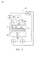
1つの実施形態に係る処理システム100は、基板125を支持するように構成された台120を有する処理チャンバ110を含んで図2に記載され、そこでは、処理プロセス、例えばエッチング後の処理プロセスは、実行される。基板125は、たとえば、半導体基板、ウェハ、または液晶ディスプレイであることができる。加えて、ラジカル発生システム115は、ラジカル送出システム140を介して、処理チャンバ110に結合される。
A
処理チャンバ110は、ダクトおよび圧力制御システム(例えば真空弁など)を介して真空排気システム170に更に結合され、そこにおいて、排気システム170は、基板125の処理プロセスを実行するのに適している圧力に、およびラジカル発生システム115のラジカルの生産に適している圧力に、処理チャンバ110、ラジカル送出システム140、およびラジカル発生システム115を排気するように構成されている。
The
なお図2を参照し、ラジカル発生システム115は、1つ以上のガス供給導管162を介してガス供給システム160から供給されたプロセスガスから原子ラジカルもしくは分子ラジカルまたはそれら両方を、離れて生成するように構成される。ラジカル発生システム115にて離れて形成されるラジカルは、ラジカル送出システム140を介して移送され、基板125より上の処理空間145に導入される。ラジカル送出システム140は、処理空間145にラジカルを導入し、一方でラジカルの流れに対して最小のインピーダンスを提供し、基板表面に到達する前にラジカルの再結合を抑制する。たとえば、ラジカル送出システムは、ダクト入口がラジカル発生システム115の出口に結合され、ダクト出口が処理チャンバ110に結合されたダクトを含むことができる。
Still referring to FIG. 2, the
ラジカル発生システム115は、基板125に対する最小のダメージで、化学的に何らかの残っているマスク層または残渣のフォトレジスト、エッチング後の残渣と反応し、除去するように構成された1つ以上の化学ラジカルを発生するように構成される。たとえば、ラジカル発生システム115は、酸素含有ガスもしくは弗素含有ガス、または両方を含んでいるプロセスガスから、酸素または弗素ラジカルを生成するように構成されたアップストリームプラズマソースを含むことができる。例えば、プロセスガスは、それぞれ、酸素(O2)、CO、CO2、NO、NO2、N2O、(またはさらに一般的にいえば、NxOy)、N2、窒素三フッ化物(NF3)、NH3、O3、XeF2、ClF3、またはC3F8(またはさらに一般的にいえば、CxFy)またはそれらの2つ以上の何らかの組合せを含むことができる。ラジカル発生システム115は、MKS Instruments社から市販されているASTeX(登録商標)製品(90 Industrial Way、ウィルミントン、MA 01887)であるアストロン(登録商標)反応性ガス発生器を含むことができる。
The
ラジカル発生システム115にプロセスガスを供給することに加えて、ガス供給システム160は、1つ以上のガス供給導管162を介してラジカル発生システム115に補助プロセスガスを供給するように、更に構成されることができる。補助プロセスガスは、ラジカル発生システム115にて形成されたラジカルの処理空間145への移送をアシストするためのキャリヤガスとして利用されることができ、または、補助プロセスガスは、プロセスガスおよびプロセスガスから形成されたラジカルを希釈するように利用されることができる。補助ガスは、不活性ガス、例えば希ガス(すなわちHe、Ne、Ar、Kr、Xe)もしくは窒素(N2)またはそれらの組合せを含むことができる。たとえば、酸素(O2)を有するラジカル発生システム115への窒素の追加は、O2の解離をアシストすることができる。さらにまた、ガス供給システム160は、1つ以上の補助ガス供給導管164を介して処理チャンバ110に直接補助プロセスガスを導入するように構成されることができる。
In addition to supplying process gas to the
図示はしていないが、ガス供給システム160は、1つ以上のガス供給源、1つ以上のコントロールバルブ、1つ以上のフィルタ、および/または1つ以上のマスフローコントローラを含むことができる。例えば、プロセスガスまたは補助プロセスガスの流量は、ほぼ1sccm(標準状態の1分あたりの立方センチメートル)から、ほぼ10000sccm(または1分につき標準状態で10リットル、slm)までの範囲とすることができる。たとえば、プロセスガスまたは補助プロセスガスの流量は、約1slmから約5slmまでの範囲とすることができる。更なる実施例として、プロセスガスまたは補助プロセスガスの流量は、約3slmから約5slmまでの範囲とすることができる。
Although not shown, the
ラジカル発生システム115からのダウンストリームで、ラジカルは、ラジカル送出システム140を介し、処理チャンバ110内の処理空間145に流れる。ラジカル送出システム140は、温度を制御するために、気相ライン温度制御システム(図示せず)に結合されることができる。たとえば、温度は、ほぼ20℃からほぼ100℃までの範囲の値にセットされることができ、別の実施例として、温度は約40℃から約80℃までの範囲の値にセットされることができる。加えて、たとえば、ラジカル送出システム140は、約50リットル/秒を上回る高コンダクタンスによって特徴づけられることができる。
Downstream from the
一旦ラジカルフローが処理空間145に入ると、ラジカルは、化学的に基板125の表面上の残渣と反応する。台120は、温度制御システム130に結合されている台120の中に埋め込まれた加熱部材135によって基板125の温度を上昇させるように構成される。加熱部材135は、抵抗加熱部材であることができ、または、加熱部材135は、熱電デバイスのアレイを含むことができる。基板ホルダ内の熱電デバイスの使用に対する付加的な詳細は、係属中の米国特許出願番号10/809,787号の名称「急速な温度変化および制御のための方法および装置」で提供され、その全体の内容は、参照によってここに取り入れられる。たとえば、温度制御システム130は、ほぼ500℃まで基板125の温度を上昇させるように構成されることができる。1つの実施形態において、基板温度は、約40℃から約500℃までの範囲とすることができる。別の実施形態において、基板温度は、約100℃から約300℃までの範囲とすることができる。加えて、処理チャンバ110は、チャンバ壁の温度を制御するように構成された温度制御システム130に結合されることができる。
Once the radical flow enters the
基板125の温度を上昇させることに加えて、台120は、処理の間、基板125を支持するように構成される。台120は、台120の上面およびおよび処理チャンバ110の移送面へ、およびその面から垂直に基板125を移動するために3つ以上のリフトピンを上下させることが可能なリフトピンアセンブリ(図示せず)を更に備えることができる。
In addition to raising the temperature of the
リフトピンアセンブリにおいて、基板リフトピンは、共通のリフトピン部材に結合されることができ、台120の上面の下でまで降ろされることができる。
In the lift pin assembly, the substrate lift pins can be coupled to a common lift pin member and can be lowered down below the top surface of the
たとえば、電気駆動システム(電気ステッパーモータ、およびねじ付きロッドを有する)または空気圧式駆動システム(エアーシリンダを有する)を利用する駆動機構(図示せず)は、共通のリフトピン部材を上下させる方法を提供する。基板125は、ゲートバルブ(図示せず)およびチャンバフィードスルー通路を通って処理チャンバ110との間で移送されることができ、移送面で位置合わせされることができ、ロボット移送システム(図示せず)を介して、基板リフトピンによって受けられることができる。一旦基板125が移送システムから受けられると、それは、基板リフトピンを降下させることによって台120の上面まで降ろされることができる。
For example, a drive mechanism (not shown) that utilizes an electric drive system (with an electric stepper motor and a threaded rod) or a pneumatic drive system (with an air cylinder) provides a way to raise and lower a common lift pin member To do. The
本発明の発明者は、エッチング後のクリーニングシステムのような従来の処理システムが、基板を保持する基板クランプ機構(例えば静電チャック)および/またはウェハの温度コントロールを容易にする基板裏面ガスフローシステムを含むことを認めている。このような形態が、本発明のいくつかの実施形態によって使用されることができる一方、本発明の発明者は、基板クランピング、および/またはウェハ裏面ガスフローは、エッチング後のクリーニングプロセスに対して、特にリモートラジカル発生器が使用されるところでは、必要でないと決定した。すなわち、本発明の発明者は、エッチング後のクリーニングシステムの台がコストを実質的に減少するために単純化されることができることを見いだした。したがって、本発明の1つの実施形態に係る処理システムは、クランプ機構を有しない台を含むか、裏面ガスフロー機構を有しないか、または、これらの形態のどちらも有しない。 The inventor of the present invention has found that a conventional processing system, such as a post-etch cleaning system, facilitates substrate clamping mechanisms (eg, electrostatic chucks) that hold the substrate and / or temperature control of the wafer. Is allowed to be included. While such a configuration can be used by some embodiments of the present invention, the inventors of the present invention have found that substrate clamping, and / or wafer backside gas flow can be used for post-etch cleaning processes. In particular, it was decided that it was not necessary where remote radical generators were used. That is, the inventors of the present invention have found that the post-etching cleaning system platform can be simplified to substantially reduce costs. Thus, a processing system according to one embodiment of the present invention includes a platform that does not have a clamping mechanism, does not have a backside gas flow mechanism, or has neither of these forms.
基板の台120上での移動またはスリップを防止するために、台120の上面は1つ以上の溝によって切り目をつけられることができる。そこにおいて、1つ以上の溝のうちの少なくとも1つは台のエッジに延びる。台120の上面に対する基板125の移動の間、台120の上面の1つ以上の溝は、たとえば、基板125の動き(またはすべり)を可能にすることができる潤滑層の形成を最小にする。1つ以上の溝のうちの少なくとも1つは、基板125の裏面と、台120の上面との間に閉じ込められ、潤滑層の形成が生じ得る雰囲気ガスの漏出を可能にするために台120のエッジまで延びる。
In order to prevent movement or slipping of the substrate on the
さらに、台120の上面からの基板125の移動の間、まず最初に台120の上面から基板125を移動するときに、台120の上面の1つ以上の溝は、たとえば、台120に基板125のくっつき(吸込みによる)を最小にする。1つ以上の溝のうちの少なくとも1つは、基板リフトオフを容易にするために基板125の裏面と、台120の上面との間の雰囲気ガスの侵入を可能にするために、台120のエッジまで延びる。
Further, during the movement of the
ここで図9〜図11を参照し、いくつかの実施例は、1つ以上の溝を有する台の上面に切り目をつけて提供される。図9〜図11に示されるいずれかの台構成は、ここで開示される処理システムのいずれにも使用されることができる。図9は、溝701の第1のアレイと、実質的に矩形のパターンを形成する溝702の第2のアレイとを有する台120を記載する。溝701の第1のアレイと、溝702の第2のアレイとは、互いに対して実質的に垂直で、台120の周囲エッジまで延びる。図10は、実質的に半径方向の溝801の第1のアレイと、実質的に円形パターンを形成する実質的に円形溝802の第2のアレイとを有する台120’を記載する。溝801の第1のアレイと、溝802の第2のアレイとは、実質的に互いに垂直であり、半径方向の溝801の第1のアレイは、台120’の周囲エッジまで延びる。図11は、台120’’の周囲エッジに延びる実質的に半径方向の溝901のアレイを有する台120’’を記載する。
Referring now to FIGS. 9-11, some embodiments are provided with a notch on the top surface of the platform having one or more grooves. Any of the platform configurations shown in FIGS. 9-11 can be used in any of the processing systems disclosed herein. FIG. 9 describes a
図2にて図示したように、排気ラインは、処理チャンバ110を真空排気システム170に接続する。真空排気システム170は、所望の真空度に処理チャンバ110を排気し、プロセスの間、処理チャンバ110からガス種を除去するための真空ポンプを含む。自動圧力コントローラ(APC)、および、オプションのトラップは、真空ポンプと直列に使用されることができる。真空ポンプは、ドライ荒引きポンプを含むことができる。別の形態として、真空ポンプは、1秒あたり5000リットル(および、より高い)まで、排気送り(feed)が可能なターボ分子ポンプ(TMP)を含むことができる。プロセス中、プロセスガス、もしくは補助プロセスガス、またはそれらの何らかの組合せは、処理チャンバ110に導入されることができ、チャンバ圧力は、APCによって調整されることができる。たとえば、チャンバ圧力は、ほぼ1mTorrからほぼ50Torrまでの範囲とすることができ、更なる実施例で、チャンバ圧力は、約1Torrから約10Torrまでの範囲とすることができる。APCは、バタフライ形式バルブまたはゲートバルブを含むことができる。トラップは、処理チャンバ110から副生成物を収集することができる。
As illustrated in FIG. 2, the exhaust line connects the
加えて、処理システム100内の何らかの部材は、セラミック材料、例えば酸化アルミニウムまたはイットリウム酸化物でコーティングされることができる。たとえば、何らかの部材は、Al2O3、Sc2O3、Sc2F3、YF3、La2O3、Y2O3、および、DyO3からなる群から選択される材料でコーティングされることができる。
In addition, any component in the
なお図2を参照し、処理システム100は、処理システム100の操作、および、その操作を制御するように構成されたコントロールシステム180を更に含むことができる。コントロールシステム180は、処理チャンバ110、台120、温度制御システム130、ラジカル発生システム115、ガス供給システム160、および真空排気システム170に結合される。
Still referring to FIG. 2, the
コントロールシステム180は、マイクロプロセッサ、メモリ、および、処理システム100と通信し、処理システム100からモニター出力と同様に処理システム100の入力をアクティブにするために十分な制御電圧を生成することが可能なデジタル入出力ポートを含むことができる。
The
さらに、コントロールシステム180は、処理チャンバ110、台120、温度制御システム130、ラジカル発生システム115、ガス供給システム160、および、真空排気システム170に結合され、それらと情報を交換する。メモリに格納されたプログラムは、保存されたプロセスレシピによって処理システム100の上記コンポーネントの制御に利用される。処理システムのコントロールシステム180の1つの実施例は、テキサス、ダラスのデル社から入手可能なデルプレシジョンワークステーション610(登録商標)である。コントロールシステム180は、また、汎用コンピュータ、デジタル信号プロセスなどとして実行されることができる。
In addition, the
しかしながら、メモリに含まれる1つ以上の命令の1つ以上のシーケンスを実行しているプロセッサに応答して本発明の処理ステップに基づいてマイクロプロセッサの部分または全てを実行する汎用計算機システムとして、コントロールシステム180は、実行されることができる。このような命令は、別のコンピュータの読み取り可能な媒体、例えばハードディスクまたはリムーバブルメディアドライブから、コントローラメモリに読み込まれることができる。マルチプロセッシング装置の1つ以上のプロセッサは、また、主メモリに含まれる命令のシーケンスを実行するために、コントローラマイクロプロセッサとして使用されることができる。代わりの実施例では、配線による回路は、ソフトウェア命令の代わりにまたは結合して使用されることができる。したがって、実施形態は、ハードウェア回路、および、ソフトウェアの何らかの特定の組合せに限定されない。
However, as a general purpose computer system that executes part or all of a microprocessor based on the processing steps of the present invention in response to a processor executing one or more sequences of one or more instructions contained in memory, the
本発明の教示に係るプログラムされた命令を保持するために、および、本発明を実施するのに必要であるデータ構造、テーブル、レコード、または他のデータを保存するために、コントロールシステム180は、少なくとも1つのコンピュータ読み取り可能な媒体またはメモリ、例えばコントローラメモリを有する。コンピュータ読み取り可能なメディアの実施例は、コンパクトディスク、ハードディスク、フロッピー(登録商標)ディスク、テープ、光磁気ディスク、PROM(EPROM、EEPROM、フラッシュEPROM)、DRAM、SRAM、SDRAM、または、他のいかなる磁気媒体、コンパクトディスク(例えばCD―ROM)、または他のいかなる光学的媒体、パンチカード、紙テープ、または、孔パターンを有する他の物理メディア、搬送波(carrier wave)(以下に記載する)、またはコンピュータが読むことができる他のいかなる媒体でもある。
To maintain programmed instructions according to the teachings of the present invention and to store data structures, tables, records, or other data necessary to implement the present invention, the
コンピュータ読み取り可能なメディアのどれかの、または組合せに保存された本発明は、コントロールシステム180を制御するための、本発明を実施するためのデバイスまたは複数のデバイスを駆動するための、および/またはコントローラが人間のユーザと相互に作用することを可能にするためのソフトウェアを含む。このようなソフトウェアは、デバイスドライバ、オペレーティングシステム、開発ツール、および、アプリケーションソフトを含むが、これらに限定されるものではない。このようなコンピュータ読み取り可能なメディアは、本発明を実施する際に実行されるプロセスの全部又は一部(もしプロセスが分配されるならば)を実行するための本発明のコンピュータプログラム製品を更に含む。
The present invention stored on any or combination of computer readable media is for controlling the
本発明のコンピューターコードデバイスは、スクリプト、解釈可能な(interpretable)プログラム、ダイナミックリンクライブラリ(DLL)、Java(登録商標)クラス、および、完成した(complete)実行可能プログラムを含むがこれに限定されない何らかの解釈可能な、または実行可能コードメカニズムであることができる。さらに、本発明のプロセスの部分は、より良好な性能、信頼性、および/または費用のために分配されることができる。 The computer code device of the present invention includes any script including, but not limited to, a script, an interpretable program, a dynamic link library (DLL), a Java class, and a complete executable program. It can be an interpretable or executable code mechanism. Further, portions of the process of the present invention can be distributed for better performance, reliability, and / or cost.
ここで使用する用語「コンピュータ読み取り可能な媒体」は、実行のためのコントロールシステム180のプロセッサに命令を提供する際に関係する何らかの媒体を指す。コンピュータ読み取り可能な媒体は、不揮発性のメディア、揮発性のメディア、および、伝送メディアを含むがこれに限定されるものではない多くの形態をとることができる。不揮発性のメディアは、たとえば、光学的、磁気的ディスク、および、光磁気ディスク、例えばハードディスクまたはリムーバブルメディアドライブを含む。揮発性のメディアは、ダイナミックメモリ、例えば主メモリを含む。さらに、コンピュータ読み取り可能なメディアの多数の形態は、実行のためのコントローラのプロセッサに1つ以上の命令の1つ以上のシーケンスを実行する際に含まれることができる。たとえば、命令は、まず最初にリモートコンピュータの磁気ディスク上に移動されることができる。リモートコンピュータは、遠く離れて、本発明の全てまたは一部を実施するための命令をダイナミックメモリへロードすることができ、コントローラ180にネットワーク上で命令を送ることができる。
The term “computer-readable medium” as used herein refers to any medium that participates in providing instructions to the processor of
コントロールシステム180は、処理システム100に対して近くで位置づけられることができ、または、それは、インターネットまたはイントラネットを介して処理システム100に対して遠く離れて位置づけられることができる。したがって、コントロールシステム180は、直接接続、イントラネット、またはインターネットの少なくとも1つを使用して処理システム100とデータを交換することができる。コントロールシステム180は、顧客サイト(すなわちデバイスメーカーなど)でイントラネットに接続することができ、またはベンダーサイト(すなわち装置製造業者)で、イントラネットに接続することができる。さらにまた、別のコンピュータ(すなわちコントローラ、サーバなど)は、直接接続、イントラネット、またはインターネットの少なくとも1つを介してデータを交換するために、コントロールシステム180にアクセスすることができる。
The
上記の如く、図2の処理システム100は、処理チャンバ内の基板にラジカルのリモート生成、および、このようなラジカルの送出を提供する。このような構成は、基板の付近の高エネルギーに電荷したパーティクルによって引き起こされ得る基板へのダメージを最小にする一方で、基板の処理、例えばエッチング後のクリーニングを可能とする。しかしながら、リモートラジカル発生器の使用は、基板の処理速度を低下させることとなり得て、および/または基板の不均一性処理を生じることとなり得る。本発明の発明者は、基板での処理速度に影響を及ぼすラジカルの速度の再結合として同様に、ラジカル送出システムのジオメトリのような設計特徴がラジカルの一様分布に影響を及ぼすことができることを見いだした。通常、基板表面に対するラジカルの妨げられてない流れは、処理速度を改良するように再結合を減少するが、処理の不均一性を提供する。逆にいえば、ガス流れに対する障害(例えば分配プレート)を提供することは、均一性を改良することができるが、処理速度を減少することになり得る。したがって、本発明の実施形態は、均一な基板処理および/または基板処理速度を制御する異なるラジカル送出システムを含む。
As described above, the
ここで図3を参照し、処理システム200は、別の実施形態に係るものを示す。処理システム200は、たとえば、図2の実施形態に類似したものであることができ、そこにおいて、同じであるか同様のコンポーネントを示すように、同様の参照番号を付す。処理システム200は、ダクト242を介してラジカル発生システム115の出口に結合されたガス分配プレナム244を有するラジカル送出システム240を備えている。ガス分配プレナムは、ガス分配プレート246に形成された複数の開口を介して処理空間245内に、ダクト242から受けとったラジカルを分配する。ガス分配プレナム244は、実質的に円筒状ボリュームを備えている。
With reference now to FIG. 3, a
ガス分配プレート246は、ほぼ1個の開口からほぼ1000個の開口までの数の範囲として、望ましくは、ほぼ10個の開口からほぼ100個の開口までの数の範囲としての複数の開口を有して設計されていることができる。加えて、たとえば、ガス分配プレート246は、複数の開口を有して設計されていることができ、そして、各々の開口が、ほぼ1mmからほぼ100mmまでの範囲として、望ましくは、ほぼ4mmからほぼ10mmまでの範囲とする直径を有する。さらにまた、たとえば、ガス分配プレート246は、複数の開口を有して設計されていることができ、そして、各々の開口が、ほぼ1mmからほぼ100mmまでの範囲として、および、望ましくは、ほぼ2mmからほぼ20mmまで範囲とする長さを有する。
The
1つの実施形態において、1つ以上の開口は、ガス分配プレート246に均一に分配される。別の形態として、もう一つの実施例では、1つ以上の開口の分配は、均一でない。たとえば、ガス分配プレート246の中央域の範囲内よりも多くの開口が、ガス分配プレート246の周辺領域内にあることができる。
In one embodiment, the one or more openings are evenly distributed to the
ガス分配プレート246は、アルミニウムまたは陽極処理アルミニウムのような金属、またはセラミックで製作されることができる。たとえば、ガス分配プレート246は、石英、シリコン、窒化シリコン、炭化珪素、アルミナ、窒化アルミニウムなどから製作されることができる。加えて、ガス分配プレート246は、セラミック材料、例えば酸化アルミニウムまたはイットリウム酸化物でコーティングされることができる。たとえば、ガス分配プレート246は、Al2O3、Sc2O3、Sc2F3、YF3、La2O3、Y2O3、および、DyO3からなる群から選択される材料でコーティングされることができる。
The
ここで図4を参照して、処理システム300は、別の実施形態に係るものが示される。そこにおいて、処理システム300は、たとえば、図2の実施形態に同様であることができ、似た参照番号が、同じであるか同様のコンポーネントを示すように付される。処理システム300は、ラジカル発生システム115の出口に結合されたガス拡散体344を有するラジカル送出システム340を備えている。ガス拡散体344は、ガス拡散体(gas diffuser)344の出口に結合するガス分配プレート346に形成された複数の開口を介して処理空間345内にラジカル発生システム115から受け取られたラジカルを分配する。たとえば、ガス拡散体344は、実質的に円錐ボリュームを含む。加えて、たとえば、図4に示すように、ガス拡散体344は、第2のエントラント領域343に結合された第1のエントラント領域342を含むことができる。第1のエントラント領域342、および、第2のエントラント領域343は、たとえば、実質的に円錐であることができる。そこにおいて、第1のエントラント領域342の半角(half angle)は、第2のエントラント領域343の半角未満である。たとえば、第1のエントラント領域342の半角は、ほぼ45度以下であることができる。別の形態として、たとえば、第1のエントラント領域342の半角は、ほぼ20度以下であることができる。あるいは、まだ、たとえば、第1のエントラント領域342の半角は、ほぼ15度以下であることができる。ガス分配プレート346は、たとえば、図3の実施形態に同様であることができる。
Referring now to FIG. 4, a
ここで図5を参照して、処理システム400は、別の実施形態に係るものが記載されている。処理システム400は、たとえば、図2の実施形態に同様であることができ、そこにおいて、類似の参照番号が、同じであるか同様のコンポーネントを示すように付されている。処理システム400は、ラジカル発生システム115の出口に結合されたガス拡散体444を有するラジカル送出システム440を備えている。ガス拡散体444は、処理空間445内にラジカル発生システム115から受け取られたラジカルを分配する。たとえば、ガス拡散体444は、実質的に円錐ボリュームを含む。加えて、たとえば、図5に示すように、ガス拡散体444は、第2のエントラント領域443に結合された第1のエントラント領域442を含むことができる。第1のエントラント領域442、および、第2のエントラント領域443は、たとえば、実質的に円錐であることができ、そこにおいて、第1のエントラント領域442の半角は、第2のエントラント領域443の半角未満である。たとえば、第1のエントラント領域442の半角は、ほぼ45度以下であることができる。別の形態として、たとえば、第1のエントラント領域442の半角は、ほぼ20度以下であることができる。あるいは、まだ、たとえば、第1のエントラント領域442の半角は、ほぼ15度以下であることができる。
Here, referring to FIG. 5, a
ここで図6Aおよび図6Bを参照して、処理システム500は、別の実施形態に係るものが記載されている。そこにおいて、処理システム500は、たとえば、図2の実施形態に同様であることができ、類似の参照番号が、同じであるか同様のコンポーネントを示すように付されている。処理システム500は、ラジカル発生システム115の出口に結合されたガス拡散体544を有するラジカル送出システム540を含む。ガス拡散体544は、処理空間545内にラジカル発生システム115から受け取られるラジカルを分配する。たとえば、ガス拡散体544は、実質的に円錐ボリュームを含む。加えて、たとえば、図6Aに示すように、ガス拡散体544は、第2のエントラント領域543に結合された第1のエントラント領域542を含むことができる。第1のエントラント領域542、および、第2のエントラント領域543は、たとえば、実質的に円錐であることができる。そこにおいて、第1のエントラント領域542の半角は第2のエントラント領域543の半角未満である。たとえば、第1のエントラント領域542の半角は、ほぼ45度以下であることができる。別の形態として、たとえば、第1のエントラント領域542の半角は、ほぼ20度以下であることができる。あるいは、たとえば、第1のエントラント領域542の半角は、ほぼ15度以下であることができる。
6A and 6B, a
図6Aおよび図6Bに示すように、拡散体プレート546は、第1のエントラント領域542の出口と、ガス拡散体544の第2のエントラント領域543の入口との間に位置づけられる。別の形態として、拡散体プレート546は、ガス拡散体544の第2のエントラント領域543の出口に位置づけられる。拡散体プレート546は、中央ボディ548、例えばディスクを含み、そして、1つ以上の支持アーム547(2本の支持アームは、図6Bに示される)で支えられ、そして、ラジカルが流れることができる1つ以上の通路549(2つの通路は、図6Bに示される)を残している。中央ボディ548は、円形、矩形、または何らかの形状であることができ、ラジカル発生システム115の出口から放射しているガス流れの軸方向の運動量を拡散するように構成される。任意に、図4にて図示したように、ガス分配プレートは、また、拡散体プレート546のダウンストリームに使用されることができる。
As shown in FIGS. 6A and 6B, the
拡散体プレート546は、アルミニウムまたは陽極処理アルミニウムのような金属、またはセラミックで製作されることができる。たとえば、拡散体プレート546は、石英、シリコン、窒化シリコン、炭化珪素、アルミナ、窒化アルミニウムなどから製作されることができる。加えて、拡散体プレート546は、セラミック材料、例えば酸化アルミニウムまたはイットリウム酸化物でコーティングされることができる。たとえば、拡散体プレート546は、Al2O3、Sc2O3、Sc2F3、YF3、La2O3、Y2O3、および、DyO3からなる群から選択される材料でコーティングされることができる。
The
ここで図7を参照して、処理システム600は、別の実施形態に係るものが記載される。そこにおいて、処理システム600は、たとえば、図2の実施形態に同様であることができ、類似の参照番号が、同じであるか同様のコンポーネントを示すように付される。処理システム600は、ラジカル発生システム115の出口に結合されたガス拡散体644を有するラジカル送出システム640を含む。ガス拡散体644は、処理空間645内にラジカル発生システム115から受け取られたラジカルを分配する。たとえば、ガス拡散体644は、実質的に円錐ボリュームを含む。加えて、たとえば、図7に示すように、ガス拡散体644は、第2のエントラント領域643に結合された第1のエントラント領域642を含むことができる。第1のエントラント領域642、および、第2のエントラント領域643は、たとえば、実質的に円錐であることができる。そこにおいて、第1のエントラント領域642の半角は第2のエントラント領域643の半角未満である。たとえば、第1のエントラント領域642の半角は、ほぼ45度以下であることができる。別の形態として、たとえば、第1のエントラント領域642の半角は、ほぼ20度以下であることができる。あるいは、たとえば、第1のエントラント領域642の半角は、ほぼ15度以下であることができる。
Referring now to FIG. 7, a
図7に示すように、拡散体プレート646は、第1のエントラント領域642の出口と、ガス拡散体644の第2のエントラント領域643の入口との間に位置づけられる。別の形態として、拡散体プレート646は、ガス拡散体644の第2のエントラント領域643の出口に位置づけられる。拡散体プレート646は、たとえば、図6Aおよび図6Bに示される拡散体プレート546に類似して設計されることができる;しかしながら、それは、2本以上の支持アームで支えられる円錐中央ボディ647を更に備えることができ、そして、ラジカルが流れることができる2つ以上の通路を残すことができる。円錐拡散体ボディ647は、円形、矩形、または何らかの形状であることができ、ラジカル発生システム115のアウトプットから放射しているガス流れの軸方向の運動量を拡散するように構成される。任意に、図4にて図示したように、ガス分配プレートは、また、拡散体プレート646のダウンストリームに使用されることができる。
As shown in FIG. 7, the
ここで図8Aおよび図8Bを参照して、処理システム700は、別の実施形態に係るものが記載される。処理システム700は、たとえば、図2の実施形態に同様であることができ、そこにおいて、類似の参照番号が同じであるか同様のコンポーネントを示すように付される。処理システム700は、ラジカル発生システム115の出口に結合されたガス拡散体744を有するラジカル送出システム740を含む。ガス拡散体744は、処理空間745内にラジカル発生システム115から受け取られたラジカルを分配する。たとえば、ガス拡散体744は、実質的に円錐ボリュームを含む。加えて、たとえば、図8Aに示すように、ガス拡散体744は、第2のエントラント領域743に結合された第1のエントラント領域742を含むことができる。第1のエントラント領域742、および、第2のエントラント領域743は、たとえば、実質的に円錐であることができる。そこにおいて、第1のエントラント領域742の半角は、第2のエントラント領域743の半角未満である。たとえば、第1のエントラント領域742の半角は、ほぼ45度以下であることができる。別の形態として、たとえば、第1のエントラント領域742の半角は、ほぼ20度以下であることができる。あるいは、たとえば、第1のエントラント領域742の半角は、ほぼ15度以下であることができる。
8A and 8B, a
図8Aおよび図8Bに示すように、拡散体プレート746は、ガス拡散体744の第2のエントラント領域743の出口に位置づけられる。拡散体プレート746は、たとえば、図7に示される拡散体プレート646に類似して設計されることができる。拡散体プレート746は、1つ以上の支持アームで支えられる円錐中央ボディ747を含み、そして、ラジカルが流れることができる1つ以上の通路を残すことができる。別の形態として、拡散体プレート746は、円錐中央ボディ747を支持するように構成された蒸気(vapor)分配プレートを含み、そこにおいて、複数の開口749は、円錐中央ボディ747のベースと、ガス拡散体744の第2のエントラント領域743の内壁との間の拡散体プレート746の周辺領域を通って形成される。円錐の中央ボディ747は、円形、矩形、または何らかの形状であることができ、ラジカル発生システム115のアウトプットから放射しているガス流れの軸方向の運動量を拡散するように構成される。
As shown in FIGS. 8A and 8B, the
なお図8Aおよび図8Bを参照し、処理システム700は、真空排気システム170に対する基板125の周囲エッジを越えていくプロセスガスの流れを妨げるために、台エッジリング750、および/もしくは拡散体プレートエッジリング752、または両方を更に備える。台エッジリング750、もしくは拡散体プレートエッジリング752、または両方は、ほぼ10%からほぼ80%までのどこかで、望ましくは、ほぼ20%からほぼ50%までのどこかで、基板125の周囲エッジでフロースロー(flow―through)空間を減少するように構成されることができる。これは、基板全体のラジカルのより均一な分配を提供することができ、および/または、基板の処理速度を改良することができる。
Still referring to FIGS. 8A and 8B, the
台エッジリング750、もしくは拡散体プレートエッジリング752、または両方は、アルミニウムまたは陽極処理アルミニウムのような金属、またはセラミックで製作されることができる。たとえば、各々のリングは、石英、シリコン、窒化シリコン、炭化珪素、アルミナ、窒化アルミニウムなどから製造されることができる。加えて、各々のリングは、セラミック材料、例えば酸化アルミニウムまたはイットリウム酸化物でコーティングされることができる。たとえば、各々のリングは、Al2O3、Sc2O3、Sc2F3、YF3、La2O3、Y2O3、および、DyO3からなる群から選択される材料でコーティングされることができる。
The
図12は、実施形態に係る基板から残渣を除去する方法のフローチャートを示す。フローチャート1000は、残渣を有する基板を処理チャンバの台に配置することに関する1010で開始する。台は、図9〜図11の台構成のいずれかであることができ、処理チャンバは、図2〜図8に記載されたどれか1つ、またはそれらのどれかの組み合わせを含むことができる。残渣は、エッチングプロセスから残渣を含むことができる。
FIG. 12 shows a flowchart of a method for removing residues from a substrate according to an embodiment. The
1020において、プロセスガスは、処理チャンバに結合されたラジカル発生チャンバに導入される。プロセスガスはNxOyを含むみ、そこにおいて、xおよびyは、1以上の整数である。プロセスガスは、NO、N2OもしくはNO2の1つ以上、またはそれらの2つ以上の組合せを含んでいる。望ましくは、プロセスガスはN2Oを含み、そして、ここで開示されたようなリモートラジカル発生システムを使用するときに、それは、良好な処理速度を提供すると予想される。NxOyガスは、後述するようにN2および/またはO2ガスの有無にかかわらず使用されることができる。別の形態として、プロセスガスは、酸素含有ガス、例えばO2、CO、もしくはCO2またはそれらの2つ以上の組合せを更に含む。本発明の発明者は、酸素含有ガスが基板にダメージを与える可能性のために(特にFEOLオペレーションにおいて)、局所的プラズマに対して好ましくなくなる一方、ダメージを最小にしながら、リモートラジカル発生装置で使用される酸素含有ガスが基板の処理速度を容易にすることができると認識した。別の形態として、プロセスガスは、窒素含有ガス、例えばN2、NH3もしくはNF3またはそれらの2つ以上の組合せを更に含む。別の形態として、プロセスガスは、ハロゲン含有ガス、例えばCxFyを更に含み、そこにおいて、xおよびyは1以上の整数である。あるいは、まだ、プロセスガスは、N2、および、O2を更に含む。あるいは、まだ、プロセスガスは、N2O、N2、および、O2から成る。別の形態として、プロセスガスは、不活性ガス、例えば希ガスを更に含む。 At 1020, process gas is introduced into a radical generation chamber coupled to the processing chamber. The process gas contains N x O y , where x and y are integers greater than or equal to one. The process gas includes one or more of NO, N 2 O or NO 2 , or a combination of two or more thereof. Desirably, the process gas comprises N 2 O, and when using a remote radical generation system as disclosed herein, it is expected to provide a good processing rate. N x O y gas can be used with or without N 2 and / or O 2 gas as described below. In another form, the process gas further comprises an oxygen-containing gas, such as O 2 , CO, or CO 2 or a combination of two or more thereof. The inventor of the present invention uses a remote radical generator while minimizing damage, while making it less favorable to local plasma due to the possibility of oxygen-containing gas damaging the substrate (especially in FEOL operations). It has been recognized that the oxygen containing gas can facilitate the processing rate of the substrate. In another form, the process gas further comprises a nitrogen-containing gas, such as N 2 , NH 3 or NF 3 or a combination of two or more thereof. In another form, the process gas further comprises a halogen-containing gas, such as C x F y , where x and y are integers greater than or equal to one. Alternatively, the process gas still further includes N 2 and O 2 . Alternatively, the process gas still consists of N 2 O, N 2 , and O 2 . In another form, the process gas further includes an inert gas, such as a noble gas.
たとえば、プロセスパラメータ空間は、約1〜約10Torrのチャンバ圧力、約3slmから約5slmまでの範囲のプロセスガス流量、および、約100℃から約300℃までの範囲の台の温度を含むことができる。 For example, the process parameter space can include a chamber pressure of about 1 to about 10 Torr, a process gas flow rate in the range of about 3 slm to about 5 slm, and a temperature in the range of about 100 ° C. to about 300 ° C. .
1030において、プロセスガスのラジカルは、ラジカル発生チャンバにおいて形成される。ラジカルは、プラズマを形成し、プロセスガスの解離を引き起こすことによって形成されることができる。別の形態として、プロセスガスを解離させることの他の技術は、電磁(EM)放射、例えば紫外線(UV)放射を含み、使用されることができる。 At 1030, process gas radicals are formed in a radical generation chamber. Radicals can be formed by forming a plasma and causing dissociation of the process gas. Alternatively, other techniques for dissociating the process gas include electromagnetic (EM) radiation, such as ultraviolet (UV) radiation, and can be used.
1040において、プロセスガスから形成されるラジカルは、ラジカル発生チャンバから処理チャンバまで移送される。たとえば、ラジカルは、図2〜図8に記載されたラジカル送出システムのどれか、またはそれらの何らかの組合せを介して移送されることができる。 At 1040, radicals formed from the process gas are transferred from the radical generation chamber to the processing chamber. For example, radicals can be transported via any of the radical delivery systems described in FIGS. 2-8, or some combination thereof.
1050において、基板はラジカルの流れに曝され、残渣は、除去される。ラジカル発生チャンバのプラズマに曝されない一方、基板は、ラジカルに曝されることができる。 At 1050, the substrate is exposed to a stream of radicals and the residue is removed. While not exposed to the plasma of the radical generation chamber, the substrate can be exposed to radicals.
本発明の特定の実施形態だけが、上で詳述されたが、当業者は、本発明の新規進歩の事項から逸脱することなく実施形態において多数の変更態様が可能であることを容易に理解することができる。したがって、全てのこのような変更態様は、本発明の範囲内に含まれることを目的とする。 While only specific embodiments of the present invention have been described in detail above, those skilled in the art will readily appreciate that numerous modifications can be made in the embodiments without departing from the novel advances of the present invention. can do. Accordingly, all such modifications are intended to be included within the scope of this invention.
100…処理システム、 115…ラジカル発生システム、 120…台、 125…基板、 130…温度制御システム、 135…加熱部材、 140…ラジカル送出システム、 145…処理空間、 160…ガス供給システム、 162…ガス供給導管、 164…補助ガス供給導管、170…真空排気システム、 180…コントロールシステム、 200…処理システム。
DESCRIPTION OF
Claims (27)
前記処理チャンバに結合され、プロセスガスを受けて、前記プロセスガスからラジカルを発生するように構成されたリモートラジカル発生システムと;
前記ラジカルを受け、前記処理空間内に前記ラジカルのフローを分配するように構成され、拡散体を備えた前記ガス分配システムと;
前記処理チャンバに結合され、前記処理チャンバの前記処理空間に前記基板を支持し、前記基板の温度を調整するように構成された台と;
前記処理チャンバに結合され、前記処理チャンバを排気するように構成された真空排気システムとを具備し、
前記拡散体は、前記ラジカル発生システムの出口に結合された拡散体入口と、前記処理チャンバの前記処理空間に結合された拡散体出口とを有し、実質的に円錐ボリュームと、この拡散体内に位置された円錐の中央ボディであって拡散体出口に位置された前記円錐の中央ボディとを備えており、
前記円錐の中央ボディは、前記リモートラジカル発生システムから放射している前記ラジカルの軸方向の運動量を拡散するように構成されている処理システム。 A processing chamber including a processing space;
A remote radical generation system coupled to the processing chamber and configured to receive a process gas and generate radicals from the process gas;
The gas distribution system configured to receive the radicals and distribute the flow of the radicals in the processing space and comprising a diffuser;
A platform coupled to the processing chamber and configured to support the substrate in the processing space of the processing chamber and to adjust the temperature of the substrate;
An evacuation system coupled to the processing chamber and configured to evacuate the processing chamber;
The diffuser has a diffuser inlet coupled to an outlet of the radical generation system and a diffuser outlet coupled to the processing space of the processing chamber, and substantially includes a conical volume and within the diffuser. comprises a central body before Symbol cone that is located in the diffuser outlet a central body position is conical,
A processing system in which the central body of the cone is configured to diffuse the axial momentum of the radicals radiating from the remote radical generation system.
前記ガス分配プレートは、前記ガス分配プレートを通過する1つ以上の開口を有している請求項1の処理システム。 The gas distribution system further comprises a gas distribution plate coupled to the diffuser at the diffuser outlet on the downstream side of the conical central body ;
The processing system of claim 1, wherein the gas distribution plate has one or more openings through the gas distribution plate.
前記拡散体入口と、前記拡散体出口との間の前記拡散体内に位置づけられ、前記ラジカル発生システムから前記ラジカルのフローによって実質的に位置合わせされる前記中央ボディを含む前記拡散体プレートを更に具備し、
前記ラジカルの前記フローは、前記処理空間へ前記中央ボディ周辺で前記拡散体を通過する請求項1の処理システム。
The gas distribution system comprises:
It said diffuser inlet, positioned on the diffusion body between the diffuser outlet, further comprising the diffuser plate including the central body are substantially aligned by the flow of the radicals from the radical generating system And
The processing system of claim 1, wherein the flow of radicals passes through the diffuser around the central body into the processing space.
前記ガス分配プレートは、前記ガス分配プレートを通過する1つ以上の開口を含んでいる請求項7の処理システム。 The gas distribution system further comprises a gas distribution plate coupled to the diffuser at the diffuser outlet on the downstream side of the diffuser plate,
8. The processing system of claim 7 , wherein the gas distribution plate includes one or more openings that pass through the gas distribution plate.
前記拡散体入口のすぐ近くの第1のエントラント領域と、
前記拡散体出口のすぐ近くの第2のエントラント領域とを含み、
前記第1のエントラント領域の半角は、前記第2のエントラント領域の半角未満である請求項1の処理システム。 The diffuser is
A first entrant region in the immediate vicinity of the diffuser inlet;
A second entrant region in the immediate vicinity of the diffuser outlet;
The processing system of claim 1, wherein a half angle of the first entrant region is less than a half angle of the second entrant region.
前記拡散体プレートは、前記ラジカル発生システムから前記ラジカルのフローによって実質的に位置合わせされる前記中央ボディを含み、
前記ラジカルの前記フローは、前記処理空間へ前記中央ボディ周辺で前記拡散体を通過する請求項11の処理システム。 The gas distribution system further comprises a diffuser plate positioned within the diffuser between the first entrant region and the second entrant region;
The diffuser plate includes a central body which is substantially aligned with the flow of the radicals from the radical generating system,
The processing system of claim 11 , wherein the flow of radicals passes through the diffuser around the central body into the processing space.
前記ガス分配プレートは、前記ガス分配プレートを通過する1つ以上の開口を含んでいる請求項14の処理システム。 The gas distribution system further comprises a gas distribution plate coupled to the diffuser at the diffuser outlet downstream of the diffuser plate,
The processing system of claim 14 , wherein the gas distribution plate includes one or more openings that pass through the gas distribution plate.
前記拡散体プレートは、前記ラジカル発生システムから前記ラジカルのフローによって実質的に位置合わせされる前記中央ボディを含み、
前記ラジカルの前記フローは、前記処理空間へ前記中央ボディ周辺で前記拡散体を通過する請求項11の処理システム。 The gas distribution system further comprises a diffuser plate positioned within the diffuser at the diffuser outlet;
The diffuser plate includes a central body which is substantially aligned with the flow of the radicals from the radical generating system,
The processing system of claim 11 , wherein the flow of radicals passes through the diffuser around the central body into the processing space.
少なくとも1つの前記1つ以上の溝は、前記台のエッジまで延びている請求項1の処理システム。 The platform has one or more grooves formed in an upper surface of the platform;
The processing system of claim 1, wherein at least one of the one or more grooves extends to an edge of the platform.
前記エッジリングは、前記ガス分配システムの周囲エッジに結合されたエッジリングを含んでいる請求項1の処理システム。 An edge ring coupled to the processing chamber and configured to surround the processing space to prevent radical flow from flowing beyond a peripheral edge of the substrate;
The processing system of claim 1, wherein the edge ring includes an edge ring coupled to a peripheral edge of the gas distribution system.
Applications Claiming Priority (2)
| Application Number | Priority Date | Filing Date | Title |
|---|---|---|---|
| US11/390,196 | 2006-03-28 | ||
| US11/390,196 US8034176B2 (en) | 2006-03-28 | 2006-03-28 | Gas distribution system for a post-etch treatment system |
Publications (3)
| Publication Number | Publication Date |
|---|---|
| JP2007266610A JP2007266610A (en) | 2007-10-11 |
| JP2007266610A5 JP2007266610A5 (en) | 2010-04-22 |
| JP5305316B2 true JP5305316B2 (en) | 2013-10-02 |
Family
ID=38573892
Family Applications (1)
| Application Number | Title | Priority Date | Filing Date |
|---|---|---|---|
| JP2007085108A Expired - Fee Related JP5305316B2 (en) | 2006-03-28 | 2007-03-28 | Gas distribution system for post-etch processing system |
Country Status (2)
| Country | Link |
|---|---|
| US (1) | US8034176B2 (en) |
| JP (1) | JP5305316B2 (en) |
Families Citing this family (27)
| Publication number | Priority date | Publication date | Assignee | Title |
|---|---|---|---|---|
| US8193096B2 (en) | 2004-12-13 | 2012-06-05 | Novellus Systems, Inc. | High dose implantation strip (HDIS) in H2 base chemistry |
| US8129281B1 (en) | 2005-05-12 | 2012-03-06 | Novellus Systems, Inc. | Plasma based photoresist removal system for cleaning post ash residue |
| US8057633B2 (en) * | 2006-03-28 | 2011-11-15 | Tokyo Electron Limited | Post-etch treatment system for removing residue on a substrate |
| US8715455B2 (en) * | 2007-02-06 | 2014-05-06 | Tokyo Electron Limited | Multi-zone gas distribution system for a treatment system |
| US8435895B2 (en) | 2007-04-04 | 2013-05-07 | Novellus Systems, Inc. | Methods for stripping photoresist and/or cleaning metal regions |
| KR101791685B1 (en) * | 2008-10-14 | 2017-11-20 | 노벨러스 시스템즈, 인코포레이티드 | High Dose Implantation Strip (HDIS) In H2 Base Chemistry |
| US8591661B2 (en) * | 2009-12-11 | 2013-11-26 | Novellus Systems, Inc. | Low damage photoresist strip method for low-K dielectrics |
| US20100183825A1 (en) * | 2008-12-31 | 2010-07-22 | Cambridge Nanotech Inc. | Plasma atomic layer deposition system and method |
| WO2011022749A1 (en) * | 2009-08-25 | 2011-03-03 | Silverbrook Research Pty Ltd | Method of removing photoresist and etch-residues from vias |
| US20110136346A1 (en) * | 2009-12-04 | 2011-06-09 | Axcelis Technologies, Inc. | Substantially Non-Oxidizing Plasma Treatment Devices and Processes |
| US20110143548A1 (en) | 2009-12-11 | 2011-06-16 | David Cheung | Ultra low silicon loss high dose implant strip |
| WO2011072061A2 (en) | 2009-12-11 | 2011-06-16 | Novellus Systems, Inc. | Enhanced passivation process to protect silicon prior to high dose implant strip |
| JP2013008949A (en) * | 2011-05-26 | 2013-01-10 | Hitachi Kokusai Electric Inc | Substrate placement board, substrate processing device, and manufacturing method of semiconductor device |
| US20120312234A1 (en) * | 2011-06-11 | 2012-12-13 | Tokyo Electron Limited | Process gas diffuser assembly for vapor deposition system |
| US9613825B2 (en) | 2011-08-26 | 2017-04-04 | Novellus Systems, Inc. | Photoresist strip processes for improved device integrity |
| US9245761B2 (en) | 2013-04-05 | 2016-01-26 | Lam Research Corporation | Internal plasma grid for semiconductor fabrication |
| KR101480340B1 (en) * | 2013-08-12 | 2015-01-09 | 주식회사 테라텍 | Plasma ashing process apparatus with variety plasma and thereof ashing method |
| US10351955B2 (en) * | 2013-12-18 | 2019-07-16 | Lam Research Corporation | Semiconductor substrate processing apparatus including uniformity baffles |
| US20150345019A1 (en) * | 2014-05-30 | 2015-12-03 | Applied Materials, Inc. | Method and apparatus for improving gas flow in a substrate processing chamber |
| US9514954B2 (en) | 2014-06-10 | 2016-12-06 | Lam Research Corporation | Peroxide-vapor treatment for enhancing photoresist-strip performance and modifying organic films |
| US11384432B2 (en) * | 2015-04-22 | 2022-07-12 | Applied Materials, Inc. | Atomic layer deposition chamber with funnel-shaped gas dispersion channel and gas distribution plate |
| EP3178540A1 (en) * | 2015-12-09 | 2017-06-14 | Point Engineering Co., Ltd. | Fluid permeable anodic oxide film and fluid permeable body using anodic oxide film |
| US10586696B2 (en) | 2017-05-12 | 2020-03-10 | Applied Materials, Inc. | Halogen abatement for high aspect ratio channel device damage layer removal for EPI growth |
| TWI794238B (en) * | 2017-07-13 | 2023-03-01 | 荷蘭商Asm智慧財產控股公司 | Apparatus and method for removal of oxide and carbon from semiconductor films in a single processing chamber |
| CN112908819B (en) * | 2019-12-03 | 2022-04-01 | 长鑫存储技术有限公司 | Gas distributor and processing method thereof |
| CN113448172A (en) * | 2020-03-27 | 2021-09-28 | 长鑫存储技术有限公司 | Photoresist coating device and method |
| KR20210128545A (en) * | 2020-04-16 | 2021-10-27 | 삼성디스플레이 주식회사 | Manufacturing method of display device |
Family Cites Families (23)
| Publication number | Priority date | Publication date | Assignee | Title |
|---|---|---|---|---|
| DE2439144C3 (en) * | 1974-08-14 | 1979-04-05 | Siemens Ag, 1000 Berlin Und 8000 Muenchen | Device for distributing flowing media from a flow cross-section to a different flow cross-section |
| DE69130434T2 (en) * | 1990-06-29 | 1999-04-29 | Canon Kk | Plate for working under vacuum |
| JPH05184977A (en) * | 1992-01-09 | 1993-07-27 | Toshiba Corp | Shower nozzle |
| JPH0824117B2 (en) * | 1992-10-27 | 1996-03-06 | 東京エレクトロン株式会社 | Plasma processing method |
| JPH0799162A (en) * | 1993-06-21 | 1995-04-11 | Hitachi Ltd | Cvd reactor apparatus |
| US5529657A (en) * | 1993-10-04 | 1996-06-25 | Tokyo Electron Limited | Plasma processing apparatus |
| US5571366A (en) * | 1993-10-20 | 1996-11-05 | Tokyo Electron Limited | Plasma processing apparatus |
| JP3121524B2 (en) * | 1995-06-07 | 2001-01-09 | 東京エレクトロン株式会社 | Etching equipment |
| US6616767B2 (en) * | 1997-02-12 | 2003-09-09 | Applied Materials, Inc. | High temperature ceramic heater assembly with RF capability |
| JPH1154496A (en) * | 1997-08-07 | 1999-02-26 | Tokyo Electron Ltd | Heat treatment system and gas processing system |
| JPH11297681A (en) * | 1998-04-07 | 1999-10-29 | Mitsubishi Electric Corp | Cvd apparatus for forming high permittivity thin film and method of forming high permittivity thin film |
| JP3911902B2 (en) * | 1999-04-16 | 2007-05-09 | 東京エレクトロン株式会社 | Processing apparatus and surface treatment method for metal parts |
| KR100319494B1 (en) * | 1999-07-15 | 2002-01-09 | 김용일 | Apparatus for Deposition of thin films on wafers through atomic layer epitaxial process |
| US6444039B1 (en) * | 2000-03-07 | 2002-09-03 | Simplus Systems Corporation | Three-dimensional showerhead apparatus |
| US20020144784A1 (en) * | 2001-04-06 | 2002-10-10 | Curry Don E. | Wafer processing apparatus having a chamber with an upper wall having gas supply openings formed therein which promote more even processing of a wafer |
| US6652711B2 (en) * | 2001-06-06 | 2003-11-25 | Tokyo Electron Limited | Inductively-coupled plasma processing system |
| US20040129218A1 (en) * | 2001-12-07 | 2004-07-08 | Toshiki Takahashi | Exhaust ring mechanism and plasma processing apparatus using the same |
| JP2003318155A (en) * | 2002-04-12 | 2003-11-07 | Applied Materials Inc | Gas feed system, its producing method, ashing system, and its operating method |
| JP4352783B2 (en) * | 2002-08-23 | 2009-10-28 | 東京エレクトロン株式会社 | Gas supply system and processing system |
| WO2004073850A1 (en) * | 2003-02-14 | 2004-09-02 | Tokyo Electron Limited | Gas feeding apparatus |
| US7892357B2 (en) * | 2004-01-12 | 2011-02-22 | Axcelis Technologies, Inc. | Gas distribution plate assembly for plasma reactors |
| US7273526B2 (en) * | 2004-04-15 | 2007-09-25 | Asm Japan K.K. | Thin-film deposition apparatus |
| US20070032072A1 (en) * | 2005-08-02 | 2007-02-08 | Stmicroelectronics Inc. | Nucleation layer deposition on semiconductor process equipment parts |
-
2006
- 2006-03-28 US US11/390,196 patent/US8034176B2/en not_active Expired - Fee Related
-
2007
- 2007-03-28 JP JP2007085108A patent/JP5305316B2/en not_active Expired - Fee Related
Also Published As
| Publication number | Publication date |
|---|---|
| US8034176B2 (en) | 2011-10-11 |
| JP2007266610A (en) | 2007-10-11 |
| US20070235137A1 (en) | 2007-10-11 |
Similar Documents
| Publication | Publication Date | Title |
|---|---|---|
| JP5305316B2 (en) | Gas distribution system for post-etch processing system | |
| JP4943912B2 (en) | Method for removing residues from a substrate | |
| US8057633B2 (en) | Post-etch treatment system for removing residue on a substrate | |
| KR101578939B1 (en) | Treatment system and gas distribution system | |
| US9115429B2 (en) | Dry non-plasma treatment system and method of using | |
| US7743731B2 (en) | Reduced contaminant gas injection system and method of using | |
| US20070238301A1 (en) | Batch processing system and method for performing chemical oxide removal | |
| KR101565174B1 (en) | Substrate processing method | |
| WO2009158311A2 (en) | Methods and apparatus for in-situ chamber dry clean during photomask plasma etching | |
| US7608544B2 (en) | Etching method and storage medium | |
| JP2008172184A (en) | Plasma etching method, plasma etching device, control program and computer storage medium | |
| JP2007116031A (en) | Method and apparatus for manufacturing semiconductor device, control program, and computer storage medium | |
| JP2007242753A (en) | Plasma etching method, plasma etching apparatus, control program, and computer storage medium | |
| JP2006278517A (en) | Plasma etching method, plasma etching apparatus, control program, and computer storage medium | |
| JP2011151243A (en) | Method for cleaning substrate processing device |
Legal Events
| Date | Code | Title | Description |
|---|---|---|---|
| A521 | Written amendment |
Free format text: JAPANESE INTERMEDIATE CODE: A523 Effective date: 20100304 |
|
| A621 | Written request for application examination |
Free format text: JAPANESE INTERMEDIATE CODE: A621 Effective date: 20100304 |
|
| A977 | Report on retrieval |
Free format text: JAPANESE INTERMEDIATE CODE: A971007 Effective date: 20100628 |
|
| RD04 | Notification of resignation of power of attorney |
Free format text: JAPANESE INTERMEDIATE CODE: A7424 Effective date: 20120529 |
|
| A131 | Notification of reasons for refusal |
Free format text: JAPANESE INTERMEDIATE CODE: A131 Effective date: 20120717 |
|
| A521 | Written amendment |
Free format text: JAPANESE INTERMEDIATE CODE: A523 Effective date: 20120918 |
|
| A131 | Notification of reasons for refusal |
Free format text: JAPANESE INTERMEDIATE CODE: A131 Effective date: 20121218 |
|
| A521 | Written amendment |
Free format text: JAPANESE INTERMEDIATE CODE: A523 Effective date: 20130218 |
|
| TRDD | Decision of grant or rejection written | ||
| A01 | Written decision to grant a patent or to grant a registration (utility model) |
Free format text: JAPANESE INTERMEDIATE CODE: A01 Effective date: 20130521 |
|
| RD02 | Notification of acceptance of power of attorney |
Free format text: JAPANESE INTERMEDIATE CODE: A7422 Effective date: 20130619 |
|
| RD03 | Notification of appointment of power of attorney |
Free format text: JAPANESE INTERMEDIATE CODE: A7423 Effective date: 20130619 |
|
| A61 | First payment of annual fees (during grant procedure) |
Free format text: JAPANESE INTERMEDIATE CODE: A61 Effective date: 20130619 |
|
| R150 | Certificate of patent or registration of utility model |
Free format text: JAPANESE INTERMEDIATE CODE: R150 |
|
| LAPS | Cancellation because of no payment of annual fees |