JP5305051B2 - Ceramic metal halide lamp lighting device - Google Patents
Ceramic metal halide lamp lighting device Download PDFInfo
- Publication number
- JP5305051B2 JP5305051B2 JP2011133708A JP2011133708A JP5305051B2 JP 5305051 B2 JP5305051 B2 JP 5305051B2 JP 2011133708 A JP2011133708 A JP 2011133708A JP 2011133708 A JP2011133708 A JP 2011133708A JP 5305051 B2 JP5305051 B2 JP 5305051B2
- Authority
- JP
- Japan
- Prior art keywords
- lamp
- metal halide
- light
- ceramic metal
- tubes
- Prior art date
- Legal status (The legal status is an assumption and is not a legal conclusion. Google has not performed a legal analysis and makes no representation as to the accuracy of the status listed.)
- Expired - Fee Related
Links
Images


Classifications
-
- H—ELECTRICITY
- H01—ELECTRIC ELEMENTS
- H01J—ELECTRIC DISCHARGE TUBES OR DISCHARGE LAMPS
- H01J61/00—Gas-discharge or vapour-discharge lamps
- H01J61/02—Details
- H01J61/04—Electrodes; Screens; Shields
- H01J61/10—Shields, screens, or guides for influencing the discharge
-
- H—ELECTRICITY
- H01—ELECTRIC ELEMENTS
- H01J—ELECTRIC DISCHARGE TUBES OR DISCHARGE LAMPS
- H01J61/00—Gas-discharge or vapour-discharge lamps
- H01J61/02—Details
- H01J61/30—Vessels; Containers
- H01J61/34—Double-wall vessels or containers
-
- H—ELECTRICITY
- H01—ELECTRIC ELEMENTS
- H01J—ELECTRIC DISCHARGE TUBES OR DISCHARGE LAMPS
- H01J61/00—Gas-discharge or vapour-discharge lamps
- H01J61/02—Details
- H01J61/52—Cooling arrangements; Heating arrangements; Means for circulating gas or vapour within the discharge space
-
- H—ELECTRICITY
- H01—ELECTRIC ELEMENTS
- H01J—ELECTRIC DISCHARGE TUBES OR DISCHARGE LAMPS
- H01J61/00—Gas-discharge or vapour-discharge lamps
- H01J61/92—Lamps with more than one main discharge path
Description
本発明は、セラミックメタルハライドランプ照明装置に関する。更に具体的には、複数本の発光管を有し、常に点灯し易い1本の発光管のみが点灯するセラミックメタルハライドランプ照明装置の再始動時間の短縮又は瞬時再始動の実現に関する。 The present invention relates to a ceramic metal halide lamp lighting device. More specifically, the present invention relates to reduction of restart time or realization of instantaneous restart of a ceramic metal halide lamp illumination device having a plurality of arc tubes and only one arc tube that is always lit.
高圧水銀ランプ、高圧ナトリウムランプ、メタルハライドランプ及びセラミックメタルハライドランプのような高輝度放電ランプ(以下、「HIDランプ」という。)は、電極間の放電を利用して発光する。白熱電球と比べて光束が大きいため大規模な空間の照明に適し、エネルギー効率が良いといった種々の特徴を備えている。従って、道路、店舗、工場等の照明、テレビや映画のロケーション照明、自動車や鉄道車両の前照灯として、一般に広く使用されている。 High-intensity discharge lamps (hereinafter referred to as “HID lamps”) such as high-pressure mercury lamps, high-pressure sodium lamps, metal halide lamps, and ceramic metal halide lamps emit light using discharge between electrodes. Since the luminous flux is larger than incandescent bulbs, it has various features such as being suitable for lighting in a large-scale space and having high energy efficiency. Therefore, it is generally widely used as lighting for roads, shops, factories, etc., location lighting for televisions and movies, and headlights for automobiles and railway vehicles.
HIDランプにおいて、発光物質として金属ハロゲン化物を採用したメタルハライドランプは、青白い光線を放つ高圧水銀ランプに比較して白色光(自然光)に近く優れた演色性、高い発光効率等の長所を有している。メタルハライドランプの発光管として、従来は石英製発光管が使用されていた。 In the HID lamp, metal halide lamps that employ metal halides as luminescent materials have advantages such as excellent color rendering and high luminous efficiency that are close to white light (natural light) compared to high-pressure mercury lamps that emit pale light. Yes. Conventionally, quartz arc tubes have been used as arc tubes for metal halide lamps.
最近では、発光管として、透光性セラミックス製発光管が使用されている。透光性セラミックス製発光管は、石英製発光管に比較して、格段に長寿命化が図れ、例えば、1本で24,000時間の寿命が確保できる。更に、材料のセラミックスは、発光管内に封入された金属ハロゲン化物と反応しないため、種々の金属ハロゲン化物を使用できる利点があり、且つ耐熱性が良好であるといった長所を有している。 Recently, a light-emitting ceramic arc tube has been used as the arc tube. The translucent ceramic arc tube can have a much longer life than a quartz arc tube. For example, a single translucent ceramic arc tube can secure a lifetime of 24,000 hours. Furthermore, since the material ceramics does not react with the metal halide sealed in the arc tube, there are advantages that various metal halides can be used and that the heat resistance is good.
透光性セラミックス製の発光管を使用しているメタルハライドランプは、特に、「セラミックメタルハライドランプ」と呼ばれている。 A metal halide lamp using an arc tube made of translucent ceramics is particularly called a “ceramic metal halide lamp”.
本発明者等は、セラミックメタルハライドランプの再始動時間の短縮に関する先行技術文献として、下記の特許文献を承知している。 The present inventors are aware of the following patent document as a prior art document relating to shortening the restart time of the ceramic metal halide lamp.
ランプ一般に対して、更なる長寿命化の要請がある。長寿命化の要請に応えるため、本発明者等は、1個のランプの外球内に2本の発光管を封入して、常に点灯し易い1本の発光管のみが点灯するセラミックメタルハライドランプの研究・開発を進めてきた。例えば、2本の発光管の内の常に1本の発光管のみが点灯するランプにすると、理論上、48,000時間の長寿命化が期待できる。 There is a demand for longer life for lamps in general. In order to meet the demand for longer life, the present inventors enclose two arc tubes in the outer bulb of one lamp, and a ceramic metal halide lamp in which only one arc tube is always lit. Has been researching and developing. For example, if a lamp in which only one of the two arc tubes is always turned on is theoretically expected to have a long life of 48,000 hours.
しかし、セラミックメタルハライドランプでは、点灯中の発光管を消灯して再始動すると、発光管は高温状態にあるため再始動に要する時間は比較的長く、通常、約15分間以上必要とする。2本の発光管を封入し発光管が交互に点灯する場合でも(即ち、点灯中の一方の発光管が消灯し、消灯中であった他方の発光管が再始動する場合でも)、約8分間以上必要としている。隣接する点灯発光管からの熱伝達により、他方の発光管は、たとえ消灯中であっても、かなり高温状態になっていると思われる。 However, in a ceramic metal halide lamp, when the arc tube that is turned on is turned off and restarted, the arc tube is in a high temperature state, so the time required for restart is relatively long, and usually requires about 15 minutes or more. Even when two light-emitting tubes are enclosed and the light-emitting tubes are alternately turned on (that is, even when one of the light-emitting tubes is turned off and the other light-emitting tube that has been turned off is restarted), about 8 Need more than a minute. Due to the heat transfer from the adjacent lighting arc tube, the other arc tube seems to be in a considerably high temperature state even when it is extinguished.
従って、再始動時間の短縮は、セラミックメタルハライドランプにおいて非常に重要な開発テーマとなっている。 Therefore, shortening the restart time has become a very important development theme for ceramic metal halide lamps.
なお、前掲特許文献1〜3には、本発明の特徴である、パルス電圧を高くし、更に発光中の発光管から隣接発光管への熱伝達を抑制する透光性熱遮蔽部材を備えたセラミックメタルハライドランプに関する記載は存在しない。
The above-mentioned
上述の問題に鑑みて、本発明は、複数本の発光管の内の点灯し易い1本の発光管のみが点灯するセラミックメタルハライドランプ照明装置において、再始動時間の短縮及び瞬時再始動の実現を目的とする。 In view of the above-described problems, the present invention achieves reduction in restart time and instantaneous restart in a ceramic metal halide lamp lighting device in which only one arc tube that is easily lit among a plurality of arc tubes is lit. Objective.
本発明に係るセラミックメタルハライドランプ照明装置は、セラミックメタルハライドランプと駆動回路とを備えた照明装置において、前記セラミックメタルハライドランプは、1つの外球内に複数本の発光管を有し、常に点灯し易い1本の発光管のみが点灯するランプであり、点灯中の一方の発光管から消灯中の他方の発光管への熱伝達を抑制するため、前記複数本の発光管の相互間に透光性熱遮蔽部材が配置され、前記駆動回路は、再始動の際に2.5〜4.5kVのパルス電圧を前記ランプに印加する。 The ceramic metal halide lamp illuminating device according to the present invention is an illuminating device including a ceramic metal halide lamp and a drive circuit. The ceramic metal halide lamp has a plurality of arc tubes in one outer sphere and is always easily lit. This is a lamp in which only one arc tube is turned on, and in order to suppress heat transfer from one arc tube that is lit to the other arc tube that is extinguished, light is transmitted between the plural arc tubes. A heat shielding member is disposed, and the driving circuit applies a pulse voltage of 2.5 to 4.5 kV to the lamp during restart.
更に、上記照明装置では、前記駆動回路は、再始動の際に3.0〜4.5kVのパルス電圧を前記ランプに印加してもよい。 Furthermore, in the lighting device, the driving circuit may apply a pulse voltage of 3.0 to 4.5 kV to the lamp during restart.
更に、上記照明装置では、前記透光性熱遮蔽部材は、石英ガラスから成っていてもよい。 Furthermore, in the said illuminating device, the said translucent heat shielding member may consist of quartz glass.
更に、上記照明装置では、前記透光性熱遮蔽部材は、板状体であってよい。 Furthermore, in the said illuminating device, the said translucent heat shielding member may be a plate-shaped object.
更に、上記照明装置では、前記透光性熱遮蔽部材は、各々の前記発光管を取り巻く円筒形部材であってよい。 Furthermore, in the illumination device, the translucent heat shielding member may be a cylindrical member surrounding each arc tube.
更に、上記照明装置では、前記透光性熱遮蔽部材は、各々の前記発光管を取り巻く部材であって、口径の僅かに異なる2個の試験管形状のガラス管を相互に組み合わせて形成した胴体は円筒形であり、両端部は丸く形成されていてもよい。 Furthermore, in the above-mentioned lighting device, the translucent heat shielding member is a member surrounding each arc tube, and is formed by combining two test tube-shaped glass tubes having slightly different diameters. May be cylindrical and both ends may be rounded.
更に、上記照明装置では、前記ランプは、出力190Wのランプであってよい。 Further, in the lighting device, the lamp may be a lamp having an output of 190 W.
本発明によれば、2本以上の複数本の発光管の内の点灯し易い1本の発光管のみが点灯するセラミックメタルハライドランプ照明装置において、再始動時間の短縮及び瞬時再始動の実現が出来る。 ADVANTAGE OF THE INVENTION According to this invention, in the ceramic metal halide lamp illuminating device in which only one arc tube which is easily lit among two or more arc tubes is lit, the restart time can be shortened and instantaneous restart can be realized. .
以下、本発明に係るセラミックメタルハライドランプの実施形態について、添付の図面を参照しながら詳細に説明する。なお、図中、同じ要素に対しては同じ参照符号を付して、重複する説明を省略する。 Hereinafter, embodiments of a ceramic metal halide lamp according to the present invention will be described in detail with reference to the accompanying drawings. In the drawings, the same elements are denoted by the same reference numerals, and redundant description is omitted.
[現状のセラミックメタルハライドランプ及びその再始動特性]
図1は、現状の2本の発光管を封入したセラミックメタルハライドランプ10の構成を説明する図である。図に示すように、ランプ10は、外球2の内部に2本の発光管4−1,4−2が内封されている。外球2の一方の端部には、口金6が接合されている。各発光管4−1,4−2は、マウント8により所定の位置に支持されている。
[Current ceramic metal halide lamps and their restart characteristics]
FIG. 1 is a diagram for explaining a configuration of a ceramic
発光管4−1,4−2は、いずれも透光性セラミックス製であり、発光部の最大外径は15.2mmであり、外表面の最短距離は10.8mmである。このように2本の発光管が隣接して近い距離で並んで配置されている。 The arc tubes 4-1 and 4-2 are both made of translucent ceramics, the maximum outer diameter of the light emitting portion is 15.2 mm, and the shortest distance of the outer surface is 10.8 mm. In this way, the two arc tubes are arranged adjacent to each other at a close distance.
外球2は、例えば、ホウケイ酸ガラス等の透光性の硬質ガラス製である。外球2は、最大口径の中央部、図で見て下側のトップ部及び上側の口金に接続するネック部を有するBT形をなしている。外球2には、発光管4からの光線をそのまま直線的に透す透明型外球と、内面を白色の曇りガラス状にして光線を或る程度拡散して透す拡散型外球とがある。
The
この出願書類では、「始動」は、低温状態(即ち、ランプの状態は通常のランプ周囲の外気温度、室温等と同じ状態)の発光管を点灯することをいう。「再始動」は、点灯していたランプを一度消灯して、十分冷却する前の高温状態の発光管を再び点灯させようとすることをいう。この高温状態のランプは、例えば、消灯した発光管を短時間で再点灯する場合、点灯中の発光管によって加熱された消灯中の隣接発光管を点灯する場合等のランプが挙げられる。 In this application document, “starting” refers to lighting the arc tube in a low temperature state (that is, the lamp is in the same state as the normal outside air temperature, room temperature, etc.). “Restart” refers to turning off a lamp that has been turned on once, and then turning on a light-emitting tube in a high temperature state before sufficiently cooling. Examples of the lamp in the high temperature include a lamp in a case where an extinguished arc tube is turned on again in a short time, and an extinguished adjacent arc tube heated by an lit arc tube is turned on.
また、2本の発光管を封入したセラミックメタルハライドランプにおいて、点灯中の発光管を「一方の発光管」と呼び、消灯中の発光管を「他方の発光管」と呼ぶこととする。 In a ceramic metal halide lamp in which two arc tubes are enclosed, the arc tube that is lit is referred to as “one arc tube”, and the arc tube that is not lit is referred to as “the other arc tube”.
2本の発光管4−1,4−2を封入したセラミックメタルハライドランプ10において、ランプ消灯後に直ちに再点灯操作をした場合、又は一方の発光管(点灯中)の寿命が尽きて隣接する他方の発光管(消灯中)が点灯する場合、再始動に要する時間は、通常、8分間程度必要としている。
In the ceramic
本発明者等は、一方の発光管からの熱伝達により他方の発光管に内封されたガスの温度が上昇していることが、短時間で再始動できない原因であると認識している。更に、従来の高圧ナトリウムランプ等では、外球内は真空状態であるため、2本の発光管の間の熱放射による熱伝達量は非常に少なかったが、現状のセラミックメタルハライドランプでは外球内は所定の不活性ガス(典型的には、アルゴンAr,窒素N)で満たされているために熱伝達量が大きく、短時間の再始動を更に困難にしていると認識している。なお、ガス圧は、20〜70kPaの範囲にある。20kPa未満になると、一方の発光管がリークした時、外球内で放電が発生し、他方の発光管が点灯しないおそれがあり、70kPaを超えると、外球の封止が困難になるおそれがある。 The inventors of the present invention recognize that the fact that the temperature of the gas enclosed in the other arc tube rises due to heat transfer from the one arc tube is a cause that cannot be restarted in a short time. Furthermore, in conventional high-pressure sodium lamps and the like, the outer bulb is in a vacuum state, so the amount of heat transferred by heat radiation between the two arc tubes is very small. Recognizes that since it is filled with a predetermined inert gas (typically argon Ar, nitrogen N), the amount of heat transfer is large, making restarting in a short time even more difficult. The gas pressure is in the range of 20 to 70 kPa. When the pressure is less than 20 kPa, when one of the arc tubes leaks, there is a possibility that a discharge occurs in the outer bulb and the other arc tube does not light up. When the pressure exceeds 70 kPa, it is difficult to seal the outer bulb. is there.
[再始動時間の短縮及び瞬時再始動の実現]
本発明者等は、第1段階として、再始動時間を半分の4分程度に短縮することを目標として設定した。更に、第2段階として、1分以内に短縮することを目標として設定した。
[Reduction of restart time and realization of instantaneous restart]
The inventors set the goal of reducing the restart time to about half of 4 minutes as the first stage. Furthermore, as the second stage, the goal was to shorten within 1 minute.
第1のアプローチとして、再始動時に印加されるパルス電圧を高くすることにより、再始動時間の短縮及び瞬時再始動を実現することを検討した。 As a first approach, it was studied to shorten the restart time and realize the instantaneous restart by increasing the pulse voltage applied at the time of restart.
図2は、図1に示すランプにおいて、パルス電圧Vpを順次高くしたときのパルス電圧−再始動時間特性RS−Aを説明するグラフである。このランプの出力は190Wであり、現在、パルス電圧2.3kVで使用されている。なお、ランプには、製品仕様として耐電圧値が規定されている。耐電圧値は、口金の耐電圧値、異電位導体間の距離等により決定される。図1に示すような口金をもつ一般照明用ランプ(即ち、自動車の前照灯等の特殊用途以外のランプ)では、一般に、耐電圧値は約5.0kVとなっている。従って、10%のマージンを考慮してパルス電圧Vpを2.3〜4.5kVの間で変化させて再始動時間tを求めた。 FIG. 2 is a graph for explaining the pulse voltage-restart time characteristic RS-A when the pulse voltage Vp is sequentially increased in the lamp shown in FIG. The output of this lamp is 190 W and is currently used with a pulse voltage of 2.3 kV. The lamp has a withstand voltage value as a product specification. The withstand voltage value is determined by the withstand voltage value of the base, the distance between different potential conductors, and the like. In general illumination lamps having a base as shown in FIG. 1 (that is, lamps other than special uses such as automobile headlamps), the withstand voltage value is generally about 5.0 kV. Accordingly, the restart time t was determined by changing the pulse voltage Vp between 2.3 and 4.5 kV in consideration of a 10% margin.
図2の結果より、次の事項が判明した。 From the results of FIG. 2, the following matters were found.
(1)パルス電圧Vpを3.5〜4.5kVに上げると、再始動時間tは約半分に低下する。 (1) When the pulse voltage Vp is increased to 3.5 to 4.5 kV, the restart time t decreases to about half.
(2) パルス電圧2.3kVの再始動時間は8分程度であるが、これを何等かの手段により4分程度に出来れば、同じような特性を描く限り、再始動時間tを1分以内に短縮することができる。 (2) The restart time of the pulse voltage of 2.3 kV is about 8 minutes. If this can be reduced to about 4 minutes by any means, the restart time t is within 1 minute as long as the same characteristics are drawn. Can be shortened.
発光管1本のランプの再始動時間は15分以上である。2本の発光管を交互に点灯する場合の再始動時間は8分程度である。低温状態(室温)のランプの始動時間は数秒である。従って、2本の発光管の場合、消灯中の発光管の温度上昇を現状の半分以下に抑制できれば、パルス電圧2.3kVの再始動時間は4分程度にすることが期待できる。 The restart time of the lamp with one arc tube is 15 minutes or more. The restart time when the two arc tubes are alternately lit is about 8 minutes. The starting time of the lamp in the cold state (room temperature) is several seconds. Accordingly, in the case of two arc tubes, the restart time of the pulse voltage 2.3 kV can be expected to be about 4 minutes if the temperature rise of the arc tube during extinction can be suppressed to less than half the current level.
そこで、第2のアプローチとして、消灯中の他方の発光管の温度上昇を抑制する手段を検討した。その結果、点灯中の一方の発光管と消灯中の他方の発光管との間に、熱遮蔽部材(「熱拡散部材」ともいう。)を配置することとした。良好な熱拡散性能をもつ部材を熱遮蔽部材として配置することにより、一方の発光管からの熱が熱遮蔽部材で拡散し、他方の発光管に向かって伝達するのを減少し又は他方の発光管に集中するのを阻止する。 Therefore, as a second approach, a means for suppressing the temperature rise of the other arc tube during extinction was examined. As a result, a heat shielding member (also referred to as a “heat diffusion member”) is arranged between one light-emitting tube that is turned on and the other light-emitting tube that is turned off. By disposing a member having good heat diffusion performance as a heat shielding member, heat from one arc tube is diffused by the heat shielding member, and is less transmitted to the other arc tube, or the other light emission Stop concentrating on the tube.
なお、この熱遮蔽部材は、発光管の間に配置するため、透光性であることが必要である。このような透光性熱遮蔽部材の材質として、例えば、透明石英ガラスを使用することが出来る。しかし、これに限定されない。 In addition, since this heat shielding member is arrange | positioned between an arc_tube | light_emitting_tube, it needs to be translucent. For example, transparent quartz glass can be used as the material of such a light-transmitting heat shielding member. However, it is not limited to this.
図3は、透光性熱遮蔽部材の効果を示すグラフである。パルス電圧−再始動時間特性RS−A(◆で表示)は、図2で説明した透光性熱遮蔽部材が無い場合であり、パルス電圧−再始動時間特性RS−B(□で表示)は、適当な透光性熱遮蔽部材を配置した場合である。 FIG. 3 is a graph showing the effect of the translucent heat shielding member. The pulse voltage-restart time characteristic RS-A (indicated by ♦) is the case where there is no translucent heat shielding member described in FIG. 2, and the pulse voltage-restart time characteristic RS-B (indicated by □) is This is a case where an appropriate translucent heat shielding member is disposed.
特性RS−Aと特性RS−Bとの関係において、透光性熱遮蔽部材の配置による再始動時間の短縮分をTtで示し、パルス電圧を上げることによる再始動時間の短縮分をTvで示している。 In the relationship between the characteristic RS-A and the characteristic RS-B, the shortening of the restart time due to the arrangement of the translucent heat shielding member is indicated by Tt, and the shortening of the restart time by increasing the pulse voltage is indicated by Tv. ing.
パルス電圧2.3kVにおいて、特性RS−Aでは再始動時間が8分間程度あったが、2本の発光管の間に透光性熱遮蔽部材を配置することにより、特性RS−Bでは再始動時間を4分以下に短縮出来た。また、パルス電圧2.3kVを順次上げることにより、パルス電圧2.5〜4.5kVでは、再始動時間を3分以内に短縮することができ、更にパルス電圧3.0〜4.5kVでは、再始動時間を1分以内に短縮することが出来た。 At the pulse voltage of 2.3 kV, the restart time is about 8 minutes in the characteristic RS-A, but the restart is performed in the characteristic RS-B by arranging a translucent heat shielding member between the two arc tubes. The time was shortened to 4 minutes or less. Further, by sequentially increasing the pulse voltage 2.3 kV, the restart time can be shortened within 3 minutes at the pulse voltage 2.5 to 4.5 kV, and further at the pulse voltage 3.0 to 4.5 kV, The restart time could be shortened within 1 minute.
[本実施形態に係るセラミックメタルハライドランプ照明装置]
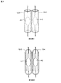
図4(A)は、本実施形態に係るセラミックメタルハライドランプ10−1の構成を説明する図である。図1のランプ10に比較して、発光管4−1,4−2の間に、透光性熱遮蔽部材12が配置されている。発光管4−1,4−2と、透光性熱遮蔽部材12との関係は、図4(B)に示す通りである。
[Ceramic metal halide lamp illumination device according to this embodiment]
FIG. 4A is a diagram for explaining the configuration of the ceramic metal halide lamp 10-1 according to the present embodiment. Compared with the
(透光性熱遮蔽部材の変形例)
図5は、図4に示すセラミックメタルハライドランプで使用される透光性熱遮蔽部材12の変形例を示す図である。透光性熱遮蔽部材12は、透光性であり、良好な熱拡散特性を有することに加えて、2本の発光管の間に配置されていれば、任意の部材であってよい。各透光性熱遮蔽部材が1本の発光管を取り巻く形状であれば、両発光管の間の熱遮蔽として一層好ましい。
(Modification of translucent heat shielding member)
FIG. 5 is a view showing a modification of the translucent
変形例1では、透光性熱遮蔽部材12−1,12−2が、各発光管4−1,4−2を夫々取り巻く円筒形状の部材となっている。変形例2では、透光性熱遮蔽部材12−3,12−4が、各発光管を夫々取り巻いており、各透光性熱遮蔽部材は、口径の僅かに異なる2個の試験管形状のガラス管を相互に組み合わせて形成して、胴体は円筒形であり、両端部は丸く閉塞(発光管につながるリード線用の開孔有り。)された部材である。 In the first modification, the translucent heat shielding members 12-1 and 12-2 are cylindrical members surrounding the arc tubes 4-1 and 4-2, respectively. In the modified example 2, the translucent heat shielding members 12-3 and 12-4 surround each arc tube, and each translucent heat shielding member has two test tube shapes having slightly different diameters. The body is formed by combining glass tubes with each other, the body is cylindrical, and both ends are closed (there is a lead wire opening connected to the arc tube).
(ランプの駆動回路)
図6は、セラミックメタルハライドランプの駆動回路を説明する図である。商用交流電源(100/200 V, 50/60Hz)14に接続された安定器16からセラミックメタルハライドランプ10に対して給電される。安定器16は、チョークコイル17及びイグナイター(始動回路)18を有している。ランプ内の発光管4−1,4−2は、電源側に対して電気的に並列に接続されている。
(Lamp drive circuit)
FIG. 6 is a diagram for explaining a drive circuit for a ceramic metal halide lamp. Power is supplied to the ceramic
図6に示すように、セラミックメタルハライドランプ照明装置では、ランプ自体に始動回路は無く、安定器16からのパルスにより、点灯し易い状態の1個の発光管が点灯する。再始動の際、イグナイター18からのパルス電圧Vpは、従来のVp=2.3kVから、Vp=3.0〜4.5kVに高く変更されている。
As shown in FIG. 6, in the ceramic metal halide lamp illuminating device, the lamp itself does not have a starting circuit, and one arc tube that is easily lit is turned on by a pulse from the ballast 16. At the time of restart, the pulse voltage Vp from the
[その他]
上述の通り、本発明を2本の発光管のランプの実施形態に沿って説明したが、本発明は、3本又はそれ以上の複数本の発光管のランプにも適用可能である。発光管相互の間に適当な透光性熱遮蔽部材を配置し、パルス電圧を順次高めて、所望の再始動時間が得られるパルス電圧を決定する。
[Others]
As described above, the present invention has been described along the embodiment of the two arc tube lamps, but the present invention is also applicable to three or more arc tube lamps. An appropriate translucent heat shielding member is disposed between the arc tubes, and the pulse voltage is sequentially increased to determine a pulse voltage that can obtain a desired restart time.
このような手順に依れば、新たな透光性熱遮蔽部材が得られ、熱遮蔽性能が向上すれば、所望の再始動時間が得られるパルス電圧はそれ以前より低くなる。 According to such a procedure, a new translucent heat shielding member is obtained, and if the heat shielding performance is improved, the pulse voltage at which a desired restart time is obtained becomes lower than before.
また、あらゆるタイプの複数本の発光管を有するランプに関しても、このような手順に依れば、所望の再始動時間が得られるパルス電圧を決定することが出来る。 Further, with respect to a lamp having a plurality of arc tubes of any type, a pulse voltage that can obtain a desired restart time can be determined according to such a procedure.
従って、本発明に係るセラミックメタルハライドランプの実施形態について説明したが、これらは例示であって、本発明の範囲を限定するものではない。当業者が、本実施形態に対して容易になしえる追加・削除・変更・改良等は、本発明の範囲内である。 Therefore, although the embodiment of the ceramic metal halide lamp according to the present invention has been described, these are examples and do not limit the scope of the present invention. Additions, deletions, changes, improvements, and the like that can be easily made by those skilled in the art with respect to the present embodiment are within the scope of the present invention.
本発明の技術的範囲は、添付の特許請求の範囲の記載によって定められる。 The technical scope of the present invention is defined by the description of the appended claims.
2:外球、 4,4−1,4−2:発光管、 8:マウント、 10:セラミックメタルハライドランプ、 12,12−1,12−2,12−3,12−4:透光性熱遮蔽部材、 14:商用交流電源、 16:安定器、 17:チョークコイル、 18:イグナイター,始動回路、
Vp:パルス電圧、 RS−A,RS−B:パルス電圧−再始動時間特性、 Tt:熱遮蔽部材の配置による再始動時間の短縮分、 Tv:パルス電圧を上げることによる再始動時間の短縮分、
2: outer sphere, 4,4-1, 4-2: arc tube, 8: mount, 10: ceramic metal halide lamp, 12, 12-1, 12-2, 12-3, 12-4: translucent heat Shielding member, 14: commercial AC power supply, 16: ballast, 17: choke coil, 18: igniter, starting circuit,
Vp: Pulse voltage, RS-A, RS-B: Pulse voltage-restart time characteristics, Tt: Reduced restart time due to arrangement of heat shield member, Tv: Reduced restart time by increasing pulse voltage ,
Claims (4)
前記セラミックメタルハライドランプは、1つの外球内に複数本の発光管を有し、常に点灯し易い1本の発光管のみが点灯するランプであり、
点灯中の一方の発光管から消灯中の他方の発光管への熱伝達を抑制するため、前記複数本の発光管の相互間に透光性熱遮蔽部材が配置され、該透光性熱遮蔽部材は、各々の前記発光管を取り巻く部材であって、口径の僅かに異なる2個の試験管形状のガラス管を相互に組み合わせて形成した胴体は円筒形であり、両端部は丸く形成されており、
前記駆動回路は、再始動の際に2.5〜4.5kVのパルス電圧を前記ランプに印加する、照明装置。 In a lighting device comprising a ceramic metal halide lamp and a drive circuit,
The ceramic metal halide lamp has a plurality of arc tubes in one outer sphere, and is a lamp in which only one arc tube that is always lit is lit.
In order to suppress heat transfer from one light-emitting tube to the other light-emitting tube, the light-transmitting heat-shielding member is disposed between the plurality of light-emitting tubes, and the light-transmitting heat-shielding member is provided. The member is a member surrounding each of the luminous tubes, and the body formed by combining two test tube-shaped glass tubes having slightly different diameters is cylindrical, and both ends are formed round. And
The said drive circuit is an illuminating device which applies the pulse voltage of 2.5-4.5 kV to the said lamp | ramp at the time of restart.
前記駆動回路は、再始動の際に3.0〜4.5kVのパルス電圧を前記ランプに印加する、照明装置。 The lighting device according to claim 1.
The said drive circuit is an illuminating device which applies the pulse voltage of 3.0-4.5 kV to the said lamp in the case of restart.
前記透光性熱遮蔽部材は、石英ガラスから成る、照明装置。 The lighting device according to claim 1 or 2,
The translucent heat shielding member is an illumination device made of quartz glass.
前記ランプは、出力190Wのランプである、照明装置。 In the illuminating device as described in any one of Claims 1-3 ,
The lamp is a lighting device having an output of 190 W.
Priority Applications (3)
| Application Number | Priority Date | Filing Date | Title |
|---|---|---|---|
| JP2011133708A JP5305051B2 (en) | 2011-06-15 | 2011-06-15 | Ceramic metal halide lamp lighting device |
| CN2012800119325A CN103403838A (en) | 2011-06-15 | 2012-05-18 | Ceramic metal halide lamp illumination device |
| PCT/JP2012/062869 WO2012172926A1 (en) | 2011-06-15 | 2012-05-18 | Ceramic metal halide lamp illumination device |
Applications Claiming Priority (1)
| Application Number | Priority Date | Filing Date | Title |
|---|---|---|---|
| JP2011133708A JP5305051B2 (en) | 2011-06-15 | 2011-06-15 | Ceramic metal halide lamp lighting device |
Publications (3)
| Publication Number | Publication Date |
|---|---|
| JP2013004286A JP2013004286A (en) | 2013-01-07 |
| JP2013004286A5 JP2013004286A5 (en) | 2013-04-11 |
| JP5305051B2 true JP5305051B2 (en) | 2013-10-02 |
Family
ID=47356920
Family Applications (1)
| Application Number | Title | Priority Date | Filing Date |
|---|---|---|---|
| JP2011133708A Expired - Fee Related JP5305051B2 (en) | 2011-06-15 | 2011-06-15 | Ceramic metal halide lamp lighting device |
Country Status (3)
| Country | Link |
|---|---|
| JP (1) | JP5305051B2 (en) |
| CN (1) | CN103403838A (en) |
| WO (1) | WO2012172926A1 (en) |
Families Citing this family (6)
| Publication number | Priority date | Publication date | Assignee | Title |
|---|---|---|---|---|
| CN104456422B (en) * | 2013-09-25 | 2018-10-12 | 海洋王(东莞)照明科技有限公司 | The reflector of gas discharge light fixture |
| CN104456167B (en) * | 2013-09-25 | 2019-05-17 | 海洋王(东莞)照明科技有限公司 | Gas discharge light fixture |
| CN104456169B (en) * | 2013-09-25 | 2019-01-15 | 海洋王(东莞)照明科技有限公司 | Gas discharge light fixture |
| CN104465313B (en) * | 2013-09-25 | 2018-05-18 | 海洋王(东莞)照明科技有限公司 | Glow discharge spot lamp |
| CN103727463A (en) * | 2013-12-31 | 2014-04-16 | 戴建国 | Ceramic composite metal lamp |
| KR200496006Y1 (en) | 2020-07-09 | 2022-10-12 | 공기영 | Metal halide lamp with heat shield plate |
Family Cites Families (13)
| Publication number | Priority date | Publication date | Assignee | Title |
|---|---|---|---|---|
| JPS54154174A (en) * | 1978-05-26 | 1979-12-05 | Mitsubishi Electric Corp | Discharge lamp |
| JP2000090879A (en) * | 1998-09-14 | 2000-03-31 | Osuramu Melco Kk | Metal halide lamp |
| JP2001319791A (en) * | 2000-05-10 | 2001-11-16 | Matsushita Electric Ind Co Ltd | Fluorescent lamp lighting device |
| JP3528794B2 (en) * | 2000-12-20 | 2004-05-24 | 松下電器産業株式会社 | Fluorescent lamp |
| JP2002190281A (en) * | 2000-12-22 | 2002-07-05 | Matsushita Electric Ind Co Ltd | High-pressure discharge lamp |
| JP3990582B2 (en) * | 2001-06-29 | 2007-10-17 | 松下電器産業株式会社 | Metal halide lamp |
| JP4861583B2 (en) * | 2001-09-25 | 2012-01-25 | 東芝ライテック株式会社 | High pressure metal vapor discharge lamp and lighting fixture |
| US6791267B2 (en) * | 2001-10-02 | 2004-09-14 | Ngk Insulators, Ltd. | High pressure discharge lamps, lighting systems, head lamps for automobiles and light emitting vessels for high pressure discharge lamps |
| DE602004025118D1 (en) * | 2003-07-25 | 2010-03-04 | Panasonic Corp | metal halide |
| JP4680663B2 (en) * | 2005-04-28 | 2011-05-11 | 篠田プラズマ株式会社 | Plasma tube array |
| JP2008234871A (en) * | 2007-03-16 | 2008-10-02 | Osram Melco Toshiba Lighting Kk | High-pressure discharge lamp and lighting fixture |
| JP4651737B2 (en) * | 2009-11-25 | 2011-03-16 | オスラム・メルコ株式会社 | High pressure discharge lamp lighting device |
| JP4853580B1 (en) * | 2010-08-10 | 2012-01-11 | 岩崎電気株式会社 | Ceramic metal halide lamp with multiple arc tubes |
-
2011
- 2011-06-15 JP JP2011133708A patent/JP5305051B2/en not_active Expired - Fee Related
-
2012
- 2012-05-18 WO PCT/JP2012/062869 patent/WO2012172926A1/en active Application Filing
- 2012-05-18 CN CN2012800119325A patent/CN103403838A/en active Pending
Also Published As
| Publication number | Publication date |
|---|---|
| WO2012172926A1 (en) | 2012-12-20 |
| CN103403838A (en) | 2013-11-20 |
| JP2013004286A (en) | 2013-01-07 |
Similar Documents
| Publication | Publication Date | Title |
|---|---|---|
| JP5305051B2 (en) | Ceramic metal halide lamp lighting device | |
| US7508134B2 (en) | Small arc tube and low-pressure mercury discharge lamp | |
| JP4853580B1 (en) | Ceramic metal halide lamp with multiple arc tubes | |
| US2103029A (en) | Electric gaseous discharge lamp | |
| JP5552936B2 (en) | Ceramic metal halide lamp with outer ball protection structure | |
| EP1607997A1 (en) | Method for producing high-pressure discharge lamp, high-pressure discharge lamp and lamp unit using such high-pressure discharge lamp, and image display | |
| JP2002015700A (en) | Fluorescent lamp | |
| JP2000067812A (en) | Compact self-ballasted fluorescent lamp | |
| JP4941793B2 (en) | Ceramic metal halide lamp | |
| JP4214826B2 (en) | Short arc type ultra high pressure discharge lamp | |
| JP2002245967A (en) | High pressure electric discharge lamp, high pressure electric discharge lamp lighting device and lighting system | |
| JP5672436B2 (en) | Ceramic metal halide lamp with outer ball protection structure | |
| JP3658926B2 (en) | Fluorescent lamp, fluorescent lamp device and lighting device | |
| JP4888674B2 (en) | Ceramic metal halide lamp with multiple arc tubes | |
| TWI679677B (en) | Electric discharge lamp | |
| JP2005203309A (en) | Discharge lamp and lighting system | |
| JP2010244831A (en) | Discharge lamp for vehicle | |
| JP2001093306A (en) | Luminaire | |
| KR100731155B1 (en) | Electrodeless xenon phosphor lamp | |
| JP2005209502A (en) | Fluorescent lamp and luminaire | |
| JP2005026212A (en) | Fluorescent lamp and lighting equipment | |
| JP2013097902A (en) | High intensity discharge lamp and aging treatment method thereof | |
| JP2004193025A (en) | Single base type fluorescent lamp | |
| JP2006048985A (en) | Metal halide lamp | |
| JP2001076673A (en) | Fluorescent lamp |
Legal Events
| Date | Code | Title | Description |
|---|---|---|---|
| A521 | Written amendment |
Free format text: JAPANESE INTERMEDIATE CODE: A523 Effective date: 20130226 |
|
| A621 | Written request for application examination |
Free format text: JAPANESE INTERMEDIATE CODE: A621 Effective date: 20130226 |
|
| A871 | Explanation of circumstances concerning accelerated examination |
Free format text: JAPANESE INTERMEDIATE CODE: A871 Effective date: 20130226 |
|
| A131 | Notification of reasons for refusal |
Free format text: JAPANESE INTERMEDIATE CODE: A131 Effective date: 20130319 |
|
| A975 | Report on accelerated examination |
Free format text: JAPANESE INTERMEDIATE CODE: A971005 Effective date: 20130314 |
|
| A521 | Written amendment |
Free format text: JAPANESE INTERMEDIATE CODE: A523 Effective date: 20130422 |
|
| A131 | Notification of reasons for refusal |
Free format text: JAPANESE INTERMEDIATE CODE: A131 Effective date: 20130513 |
|
| A521 | Written amendment |
Free format text: JAPANESE INTERMEDIATE CODE: A523 Effective date: 20130513 |
|
| TRDD | Decision of grant or rejection written | ||
| A01 | Written decision to grant a patent or to grant a registration (utility model) |
Free format text: JAPANESE INTERMEDIATE CODE: A01 Effective date: 20130529 |
|
| A61 | First payment of annual fees (during grant procedure) |
Free format text: JAPANESE INTERMEDIATE CODE: A61 Effective date: 20130611 |
|
| R150 | Certificate of patent or registration of utility model |
Free format text: JAPANESE INTERMEDIATE CODE: R150 Ref document number: 5305051 Country of ref document: JP Free format text: JAPANESE INTERMEDIATE CODE: R150 |
|
| LAPS | Cancellation because of no payment of annual fees |