JP5301397B2 - Beverage container with straw - Google Patents
Beverage container with straw Download PDFInfo
- Publication number
- JP5301397B2 JP5301397B2 JP2009208000A JP2009208000A JP5301397B2 JP 5301397 B2 JP5301397 B2 JP 5301397B2 JP 2009208000 A JP2009208000 A JP 2009208000A JP 2009208000 A JP2009208000 A JP 2009208000A JP 5301397 B2 JP5301397 B2 JP 5301397B2
- Authority
- JP
- Japan
- Prior art keywords
- straw
- state
- valve
- lock
- valve body
- Prior art date
- Legal status (The legal status is an assumption and is not a legal conclusion. Google has not performed a legal analysis and makes no representation as to the accuracy of the status listed.)
- Active
Links
Images


Landscapes
- Details Of Rigid Or Semi-Rigid Containers (AREA)
- Closures For Containers (AREA)
Description
本発明は飲料を吸入するためのストローが装着されたストロー付き飲料容器に関する。 The present invention relates to a beverage container with a straw equipped with a straw for inhaling a beverage.
従来から幼児等を使用者として想定されたストロー付き飲料容器が周知である。このような飲料容器には外部に露出するストローが未使用時に閉塞されるようにストローを折り曲げた状態で隠すことができるストローキャップが設けられている。そのストローキャップが使用時に開かれるとストローの閉塞が解除されるので、容器に収められた飲料をストローを用いて使用者が飲むことができる。 2. Description of the Related Art A beverage container with a straw, which is conventionally assumed to be an infant or the like, is well known. Such a beverage container is provided with a straw cap that can be hidden in a folded state so that the straw exposed to the outside is closed when not in use. When the straw cap is opened during use, the straw is unblocked, so that the user can drink the beverage contained in the container using the straw.
ところが、外気よりも温度が高い湯等の暖かい飲料が容器に収められている場合には密閉された容器の内圧が高まる。そのため、ストローキャップが開かれると、その開放と同時に閉塞が解除されるストローから飲料が噴出する場合がある。そこで、ストロー付き飲料容器には内圧を外部に逃がすための開閉弁が設けられていることが一般的である。 However, when a warm beverage such as hot water having a temperature higher than the outside air is contained in the container, the internal pressure of the sealed container increases. Therefore, when the straw cap is opened, the beverage may be ejected from the straw that is released from the closing simultaneously with the opening of the straw cap. Therefore, a drinking container with a straw is generally provided with an on-off valve for releasing the internal pressure to the outside.
例えば、このような開閉弁を備えたストロー付き飲料容器として、ストローキャップを閉状態に保持するロック部材と容器に設けられた空気孔を開閉する開閉弁の弁体とが一体化され、ロック部材の操作によってストローキャップのロックが解除されたときに空気孔が弁体にて開かれることにより内圧を逃がすことができる飲料容器が知られている(特許文献1)。 For example, as a beverage container with a straw provided with such an on-off valve, a lock member that holds a straw cap in a closed state and a valve body of an on-off valve that opens and closes an air hole provided in the container are integrated, and the lock member There is known a beverage container in which an internal pressure can be released by opening an air hole with a valve body when the straw cap is unlocked by the operation (Patent Document 1).
特許文献1の飲料容器は、ストローキャップのロックを解除するロック部材の操作によって内圧を逃がすことができるが、一旦開かれた空気孔を閉じるにはロック部材をストローキャップが開かれた状態で再度操作することが必要になる。つまり、ストローキャップが開かれて飲料を飲むことが可能になった後に空気孔を閉じるためのロック部材の操作を使用者に強いることになる。そのため、ロック部材に対する操作が使用者にとって煩わしいものになるおそれがある。また、ストローキャップが開かれた後に行うべきロック部材の操作を使用者が忘れた場合には空気孔が開かれたままになるので、例えば飲料容器を傾けて使用する際に空気孔からの飲料の漏れを誘発するおそれがある。
In the beverage container of
そこで、本発明は、操作に対する煩わしさを使用者に感じさせることを防止できるストロー付き飲料容器を提供することを目的とする。 Then, an object of this invention is to provide the drink container with a straw which can prevent a user from feeling troublesome to operation.
以下、本発明のストロー付き飲料容器について説明する。なお、本発明の理解を容易にするために添付図面の参照符号を括弧書きにて付記するが、それにより本発明が図示の形態に限定されるものではない。 Hereinafter, the beverage container with a straw of the present invention will be described. In order to facilitate understanding of the present invention, reference numerals in the accompanying drawings are appended in parentheses, but the present invention is not limited to the illustrated embodiment.
本発明のストロー付き飲料容器(1、1A〜1E)は、開口部(2a)を持つ容器本体(2)と、前記開口部を塞ぐようにして前記容器本体に装着されたストローアダプタ(3、3A〜3E)とを備え、前記容器本体内の飲料を吸入するためのストロー(6)が前記ストローアダプタに装着されたストロー付き飲料容器において、前記ストローを隠す閉位置と前記ストローを露出させる開位置との間で動作可能な状態で前記ストローアダプタに取り付けられたストローキャップ(9、9A〜9E)と、前記ストローキャップを前記閉位置にロックするロック位置と、そのロックを解除する解除位置との間で動作可能なロック部材(16、16A〜16E)と、前記容器本体の内外を閉鎖する閉状態と前記容器本体の内外を連通する開状態との間で状態を変更でき、所定操作を受け付けることにより前記閉状態から前記開状態へ移行するとともに、前記所定操作が解除されることにより前記開状態から前記閉状態へ復帰する開閉弁(20、20E、50)と、前記ロック位置から前記解除位置へ向かう前記ロック部材の動作を前記開閉弁に対する前記所定操作として伝達し、かつ前記ストローキャップが前記開位置に位置した状態で前記開閉弁に対する前記所定操作が解除されるように前記開閉弁から離間する伝達部材(30、30A〜30E)と、を備えることにより、上述した課題を解決する。 The beverage container with a straw (1, 1A to 1E) of the present invention includes a container body (2) having an opening (2a), and a straw adapter (3, 3) attached to the container body so as to close the opening. 3A to 3E), and a drinking container with a straw in which a straw (6) for inhaling a beverage in the container body is attached to the straw adapter, and a closed position for hiding the straw and an opening for exposing the straw. A straw cap (9, 9A to 9E) attached to the straw adapter in an operable state between positions, a lock position for locking the straw cap in the closed position, and a release position for releasing the lock A locking member (16, 16A-16E) operable between the closed state in which the inside and outside of the container body are closed, and the open state in which the inside and outside of the container body are communicated The on-off valve (20, 20E, which can change the state by receiving a predetermined operation and transitions from the closed state to the open state and returns from the open state to the closed state by releasing the predetermined operation. 50) and the operation of the lock member from the lock position to the release position is transmitted as the predetermined operation on the on-off valve, and the predetermined operation on the on-off valve in a state where the straw cap is located at the open position. And the transmission member (30, 30A to 30E) that is separated from the on-off valve so as to be released, the above-described problems are solved.
この飲料容器によれば、ロック部材のロック位置から解除位置へ向かう動作によって開閉弁が閉状態から開状態へ移行し、かつストローキャップが開位置に位置した状態で所定操作が解除されるので開閉弁が開状態から閉状態へ復帰する。そのため、ストローキャップに対するロックの解除により内圧を逃がすことができるとともに、ストローキャップが開かれた後には開閉弁が自動的に閉状態になる。従って、ストローキャップを開く際に使用者が特に意識せずに内圧を逃がすことができ、しかもストローキャップが開かれた後にロック部材に対する操作をしなくても開閉弁を通じた飲料漏れを防止できる。よって、使用時に必要な操作に対する煩わしさを使用者に感じさせることを防止できる。 According to this beverage container, the opening / closing valve shifts from the closed state to the open state by the movement of the lock member from the lock position to the release position, and the predetermined operation is released with the straw cap positioned at the open position. The valve returns from the open state to the closed state. Therefore, the internal pressure can be released by releasing the lock on the straw cap, and the open / close valve is automatically closed after the straw cap is opened. Therefore, when opening the straw cap, the user can relieve the internal pressure without being particularly aware of it, and it is possible to prevent the beverage from leaking through the on-off valve without operating the lock member after the straw cap is opened. Therefore, it is possible to prevent the user from feeling troublesome with respect to an operation required at the time of use.
開閉弁の構造や材質について格別の制限はない。例えば、前記開閉弁は、前記所定操作としての押し込み操作が前記伝達部材にて行われたときに弾性変形し得る弾性材料にて構成された弁体(21、21E)を有し、前記弁体は、前記押し込み操作による弾性変形によって前記開状態に移行し、かつ前記押し込み操作の解除による弾性変形の解消によって前記開状態から前記閉状態へ復帰するように構成されていてもよい。この態様によれば、複数の部品で開閉弁を構成しなくても、弾性材料で構成された弁体の弾性変形を利用して開状態と閉状態とを変更できるから部品点数を容易に削減できる。 There are no particular restrictions on the structure or material of the on-off valve. For example, the on-off valve has a valve body (21, 21E) made of an elastic material that can be elastically deformed when a pushing operation as the predetermined operation is performed by the transmission member. May be configured to shift to the open state by elastic deformation by the push-in operation and to return from the open state to the closed state by eliminating elastic deformation by releasing the push-in operation. According to this aspect, the number of parts can be easily reduced because the open state and the closed state can be changed using the elastic deformation of the valve body made of an elastic material without forming the on-off valve with a plurality of parts. it can.
この態様において、前記弁体は、前記容器本体の内外を区画する板部(25)と、前記板部の周囲を保持するとともに前記押し込み操作を受け付け得る筒状の保持部(26)とが一体化されており、前記板部には、前記押し込み操作の操作方向と同方向に延びて板厚方向に貫通するスリットが形成されていてもよい。この場合、弁体に対して外力が加わらない状態ではスリットが閉じられることにより弁体は閉状態に維持される。弁体の保持部に対して押し込み操作が行われるとその押し込み操作に伴って板部が変形する。その板部の変形によってスリットの両端間距離が短くなるのでスリットが開かれて閉状態から開状態へ移行する。こうした押し込み操作が解除された場合、弁体の弾性変形が解消して板部及び保持部の両者が元の状態に戻るのでスリットが閉じられて閉状態に復帰できる。 In this aspect, the valve body includes a plate portion (25) that partitions the inside and the outside of the container body, and a cylindrical holding portion (26) that holds the periphery of the plate portion and can receive the pushing operation. The plate portion may be formed with a slit extending in the same direction as the operation direction of the pushing operation and penetrating in the plate thickness direction. In this case, when no external force is applied to the valve body, the valve body is kept closed by closing the slit. When the pushing operation is performed on the holding portion of the valve body, the plate portion is deformed along with the pushing operation. Since the distance between both ends of the slit is shortened by the deformation of the plate portion, the slit is opened and the state is changed from the closed state to the open state. When such push-in operation is released, the elastic deformation of the valve body is canceled and both the plate portion and the holding portion are returned to the original state, so that the slit can be closed to return to the closed state.
この板部の形状は任意であるが、例えば、前記板部は、前記容器本体の内部側に向かって凸となる曲面状に形成されていてもよい。この場合には、板部を境にして容器本体の内部側の圧力が大気圧よりも高い圧力差が生じた場合、弁体にはスリットを密着させる方向に板部を変形させる力が作用する。そのため、内圧が大気圧より高い圧力差が生じた場合には容器本体の内から外に向かう方向の流体の通過が阻止される。従って、弁体が閉状態に保持されていれば容器本体から外部への飲料の漏れを確実に防止できる。一方、板部を境にして容器本体の内部側の圧力が大気圧よりも低い圧力差が生じた場合、つまり内圧が負圧になった場合、弁体にはスリットを開く方向に板部を変形させる力が作用する。そのため、内圧が大気圧力も低い圧力差が生じた場合には容器本体の外から内に向かう方向の流体の通過を許容することができる。従って、ストローによる飲料の吸入に伴って容器本体内の飲料量が減っていく過程で内圧が負圧になることがあるが、その場合でもその負圧の大きさがスリットが開かれる限界を超えれば弁体を介して外気が容器本体内に取り込まれる。そのため、ストローを用いて飲料を吸入する使用者に多大な吸引力が要求されることがないので使用者の負担を軽減できる。 Although the shape of this board part is arbitrary, the said board part may be formed in the curved surface shape which becomes convex toward the inner side of the said container main body, for example. In this case, when a pressure difference is generated where the pressure inside the container main body is higher than the atmospheric pressure with the plate portion as a boundary, a force that deforms the plate portion in the direction in which the slit is in close contact with the valve body acts. . Therefore, when a pressure difference in which the internal pressure is higher than the atmospheric pressure occurs, the passage of fluid in the direction from the inside of the container body to the outside is prevented. Therefore, if the valve body is held in the closed state, the leakage of the beverage from the container body to the outside can be surely prevented. On the other hand, when a pressure difference occurs between the plate part and the inner side of the container body that is lower than the atmospheric pressure, that is, when the internal pressure becomes negative, the plate is placed in the direction to open the slit in the valve body. Deformation force is applied. For this reason, when a pressure difference is generated in which the internal pressure is low and the atmospheric pressure is low, the passage of the fluid in the direction from the outside to the inside of the container body can be permitted. Therefore, the internal pressure may become negative in the process of reducing the amount of beverage in the container body as the beverage is inhaled by the straw, but even in this case, the magnitude of the negative pressure exceeds the limit for opening the slit. The outside air is taken into the container body through the valve body. For this reason, a user who inhales a beverage using a straw is not required to have a great suction force, so the burden on the user can be reduced.
弾性材料で構成された弁体を有する場合、前記ストローは前記弁体と同一材料で構成された吸い口部(7)を有し、前記吸い口部と前記弁体とが一体化されていてもよい。この場合には、ストローキャップが閉じられた際に吸い口部が容易に弾性変形できる。しかもその吸い口部と弁体とが一体化されているので部品点数を削減できる。 In the case of having a valve body made of an elastic material, the straw has a mouth portion (7) made of the same material as the valve body, and the mouth portion and the valve body are integrated. Also good. In this case, the mouthpiece can be easily elastically deformed when the straw cap is closed. Moreover, since the mouthpiece and the valve body are integrated, the number of parts can be reduced.
本発明の飲料容器の一態様において、前記ストローキャップは、支持軸(10)を介して回転自在に前記ストローアダプタに取り付けられることにより前記閉位置と前記開位置との間で動作でき、前記ロック部材は、前記ロック位置と前記解除位置との間で動作可能な状態で前記ストローキャップに設けられ、前記伝達部材は、前記ロック部材と一体移動可能な状態で前記ロック部材に設けられていてもよい。この態様によれば、ロック部材をロック位置から解除位置に向かって動作させてからストローキャップを閉位置から開位置へ動作させることにより、ストローキャップととともにロック部材と伝達部材とがストローアダプタから離れる方向に動作する。このため、伝達部材を開閉弁から離間させるために特別な装置を設けなくても、閉位置から開位置へ向かうストローキャップの動作を利用することによって伝達部材を開閉弁から容易に離間させることができる。 In one aspect of the beverage container of the present invention, the straw cap can be operated between the closed position and the open position by being rotatably attached to the straw adapter via a support shaft (10), and the lock The member is provided in the straw cap in a state operable between the lock position and the release position, and the transmission member is provided in the lock member in a state of being movable together with the lock member. Good. According to this aspect, by operating the straw member from the lock position toward the release position and then operating the straw cap from the closed position to the open position, the lock member and the transmission member are separated from the straw adapter together with the straw cap. Operate in the direction. Therefore, the transmission member can be easily separated from the on-off valve by using the operation of the straw cap from the closed position to the open position without providing a special device for separating the transmission member from the on-off valve. it can.
以上説明したように、本発明の飲料容器によれば、ロック部材のロック位置から解除位置へ向かう動作によって開閉弁が閉状態から開状態へ移行し、かつストローキャップが開位置に位置した状態で所定操作が解除されるので開閉弁が閉状態から開状態へ復帰するので、ストローキャップを開く際に使用者が特に意識せずに内圧を逃がすことができ、しかもストローキャップが開かれた後にロック部材に対する操作をしなくても開閉弁を通じた飲料漏れを防止できる。従って、使用時に必要な操作に対する煩わしさを使用者に感じさせることを防止できる。 As described above, according to the beverage container of the present invention, the opening / closing valve is shifted from the closed state to the open state by the operation of the lock member from the lock position to the release position, and the straw cap is positioned at the open position. As the specified operation is released, the on-off valve returns from the closed state to the open state, so that the user can relieve the internal pressure without opening the straw cap, and it is locked after the straw cap is opened. Beverage leakage through the on-off valve can be prevented without operating the member. Therefore, it is possible to prevent the user from feeling annoyed with the operation necessary for use.
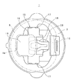
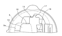
図1は本発明の一形態に係るストロー付き飲料容器の一部を切断して示した側断面図であり、図2は図1に示された飲料容器の平面図である。これらの図に示したように、ストロー付き飲料容器(以下、飲料容器という。)1は、開口部2aを持ち飲料を保持し得る容器本体2と、開口部2aを塞ぐようにして容器本体2に装着されたストローアダプタ3とを備えている。容器本体2には使用者が飲料容器1を持ち易くするために所定形状のハンドルHが一体的に形成されている。容器本体2の上部外周部には雄ねじ4が設けられており、ストローアダプタ3の内周部にはその雄ねじ4に噛み合う雌ねじ5が設けられている。ストローアダプタ3は各ねじ4、5を互いに噛み合わせた状態で容器本体2にねじ込まれることにより容器本体2に装着されている。ストローアダプタ3には容器本体2内に収められた飲料を吸入するためのストロー6が装着されている。ストロー6は、可撓性を有し使用者に咥えられる吸い口部7と、容器本体2内に収まっている本体部8とが互いに連結されることにより構成されている。吸い口部7と本体部8とは互いに異種材料で構成されている。吸い口部7は弾性変形が容易なシリコーン樹脂にて構成されており、それに連結される本体部8はプラスチックで構成されている。
FIG. 1 is a side sectional view showing a part of a beverage container with a straw according to one embodiment of the present invention, and FIG. 2 is a plan view of the beverage container shown in FIG. As shown in these drawings, a beverage container with a straw (hereinafter referred to as a beverage container) 1 has a
ストローアダプタ3には、ストロー6を隠す閉位置(図1参照)とストロー6を露出させる開位置(図7参照)との間で動作可能な状態でストローキャップ9が取り付けられている。ストローキャップ9は支持軸10を介して回転自在にストローアダプタ3に取り付けられることにより閉位置と開位置との間で動作できる。ストローキャップ9には、閉位置において折り曲げられた状態のストロー6を潰して閉塞させるための突起部11が設けられており、その突起部11はストローキャップ9が閉位置にあるときにストロー6を潰すことができるように飲料容器1の下方に突出している。
A
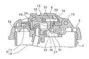
飲料容器1には、ストローキャップ9を閉位置でロックできるようにするためロック機構15が設けられている。ロック機構15は、ストローキャップ9を閉位置でロックするロック位置(図1、2)とそのロックを解除する解除位置(図5A、図5B)との間で動作可能な状態でストローキャップ9に取り付けられたロック部材16と、そのロック部材16がロック位置にあるときにロック部材16とストローアダプタ3とを噛み合わせる拘束部17(図2)と、ロック部材16をロック位置側に付勢するリターンばね18とを備えている。
The
ロック部材16はロック位置から解除位置まで水平方向に(図1の左右方向に)スライド可能である。ロック部材16はストローキャップ9の上面に形成された開口部9aから一部が露出しており、その露出した部分には使用者にて操作され得る操作部19が形成されている。拘束部17はロック部材16の動作方向と同方向に延びる溝状に構成されていて、その溝の長さはロック部材16が解除位置に達したときにロック部材16とストローアダプタ3との噛み合いが解除される長さを有している(図5A参照)。リターンばね18はシリコーン樹脂により構成されていて、ロック部材16が使用者にて解除位置まで操作されて離されるとリターンばね18の弾性力によりロック部材16はロック位置まで復帰できる。
The
飲料容器1には、内圧を外部に逃がすことができるようにするため、容器本体2の内外を閉鎖する閉状態と、容器本体2の内外を連通する開状態との間で状態を変更できる開閉弁20が設けられている。開閉弁20は、弾性変形可能な弾性材料で構成された弁体21を備えている。弁体21はストローアダプタ3に形成された貫通孔22に密着状態でストローアダプタ3に装着されている。飲料容器1においては、弁体21はストロー6の吸い口部7と同一材料であるシリコーン樹脂で構成され、かつ吸い口部7と一体に構成されている。飲料容器1は吸い口部7と弁体21とが一体化されているので部品点数の削減に寄与できる。
The
図3A及び図3Bは弁体21を上方から見た状態を拡大して示した説明図であり、図3Aはその閉状態を、図3Bはその開状態をそれぞれ示している。これらの図にも示したように、弁体21は容器本体2の内外を区画する板部25と、その板部25の周囲を保持する筒状の保持部26とを備えており、板部25には板厚方向に貫通するスリット27が形成されている。図3Aの場合には、弁体21に対して外力が加わっていないためスリット27が密着状態で閉じられるので閉状態に維持される。図3Bに示すように、弁体21の保持部26に対して矢印方向に所定操作である押し込み操作が行われるとその押し込み操作に伴って板部25が弾性変形する。スリット27は押し込み操作の操作方向に延びている。このため、板部25の弾性変形によってスリット27の両端間距離Xが図3Aの閉状態に比べて短くなるので、スリット27が図示のように開かれて閉状態から開状態へ移行する。その押し込み操作が解除された場合、弁体21の弾性変形が解消して板部25及び保持部26の両者が元の状態に戻るのでスリット27が閉じられて図3Aの閉状態に復帰できる。
3A and 3B are explanatory views showing an enlarged view of the
このような開閉弁20の弁体21に対する押し込み操作と、上述したロック機構15のロック部材16の動作とを連係させるため、図1に示すように、飲料容器1には、ロック部材16のロック位置から解除位置へ向かう動作を開閉弁20に対する押し込み操作として開閉弁20に伝達する伝達部材30が設けられている。伝達部材30はロック部材21と一体に設けられている。つまり伝達部材30はロック部材16と一体移動可能である。
In order to link the pushing operation of the on-off
図4A〜図6は、図1及び図2の状態からロック部材16が解除位置側に操作されてからストローキャップ9が開位置側に開かれるまでの飲料容器1の各部の動作を説明している。図4A及び図4Bはロック部材16に対する操作が開始されてからロック部材16と拘束部17の噛み合いが解除されるまでの間の状態を示しており、図4Aはその状態の平面図、図4Bはその状態の側断面図である。図5A及び図5Bはロック部材16と拘束部17との噛み合いが解除された状態を示しており、図5Aはその状態の平面図、図5Bはその状態の側断面図である。図6はストローキャップ9が開位置側に開かれた状態を示した側断面図である。
4A to 6 illustrate the operation of each part of the
ロック部材16に対する操作がなされていない図1及び図2の状態では、伝達部材30と開閉弁20(弁体21)とは離れていて弁体21が閉状態であり、かつストローキャップ9が閉位置にあってストロー6が閉塞されているため容器本体2は密封されている。この状態から、図4A及び図4Bに示すようにロック部材16の操作が開始されてロック部材16が解除位置側に少し動くことによって伝達部材30が弁体21の保持部26に突き当たり弁体21の弾性変形が開始する。つまり、伝達部材30によって弁体21に対して押し込み操作が開始されスリット27が開き始まる。そのため、弁体21を通じて容器本体2内の空気が矢印方向に流れ始めて飲料容器1の内圧の減少が開始する。
1 and 2 in which the
続いて、図5A及び図5Bに示すように、ロック部材16が解除位置まで動作すると、ロック部材16と拘束部17との噛み合いが解除されてストローキャップ9のロックが解除される。それと並行して、弁体21が伝達部材30によって更に押し込まれて弁体21の変形が最大となる結果、スリット27の開き具合も最大となる。それにより、ストロー6が閉鎖された状態で飲料容器1の内圧が完全に逃がされる。図5A及び図5Bに示したようにロック部材16を解除位置に維持されている間はストローキャップ9の拘束が解かれているので、ストローキャップ9を閉位置から開位置側へ動作させることができる。
Subsequently, as shown in FIGS. 5A and 5B, when the
図6に示すように、ストローキャップ9の開位置側への動作に伴って、ストローキャップ9と一緒に移動する伝達部材30が弁体21から離間するので、弁体21に対して伝達部材30にて行われていた押し込み操作が解除される。その押し込み操作の解除により弁体21の弾性変形が解消して元の状態に戻り(図3A参照)、弁体21は自動的に閉状態に復帰する。そして、ストローキャップ9の開位置側への動作によりストローキャップ9によるストロー6の閉塞が解除されてストロー6の吸い口部7が真っ直ぐに伸びた状態になりストロー6の使用が可能となる。
As shown in FIG. 6, the
このように、飲料容器1によれば、使用者がストローキャップ9のロックを解除してからストローキャップ9を開位置側へ開く過程で内圧を確実に逃がすことができる。しかも、ストローキャップ9が開かれてストロー6の使用が可能になった段階では開閉弁20が自動的に閉状態に復帰しているので、使用者が意識して開閉弁20に対して格別の操作を行うことなく使用時における開閉弁20からの飲料漏れを防止できる。従って、使用時に必要な操作に対する煩わしさを使用者に感じさせることを防止できる。また、飲料容器1は、伝達部材30がストローキャップ9に設けられたロック部材16と一体移動可能な状態でロック部材16に設けられているから、弁体21に対して押し込み操作を行っている最中の伝達部材30を開閉弁20(弁体21)から離間させるために特別な装置を設けなくても閉位置から開位置へ向かうストローキャップ9の動作を利用することにより、伝達部材30を開閉弁20から容易に離間させることができる。
Thus, according to the
飲料容器1の開閉弁20は、複数の部品で構成する場合と異なり、弾性材料で構成された単一の弁体21の弾性変形を利用して開状態と閉状態とを変更できるから部品点数を容易に削減できる。その他にも、開閉弁20は以下に説明する更なる特徴を有している。
Unlike the case where the on-off
図1及び図6等に示すように、開閉弁20は、その弁体21の板部25が容器本体2の内部側に向かって凸となる曲面状に、より具体的には球面状に形成されている。そのため、板部25を境にして容器本体2の内部側の圧力が大気圧よりも高い圧力差が生じた場合、弁体21にはスリット27を密着させる方向に板部25を変形させる力が作用する。そのため、このような圧力差が生じた場合には容器本体2の内から外に向かう方向の流体の通過が阻止される。従って、弁体21が閉状態に保持されていれば容器本体2から外部への飲料の漏れを確実に防止できる。一方、板部25を境にして容器本体2の内部側の圧力が大気圧よりも低い圧力差が生じた場合、つまり内圧が負圧になった場合、弁体21にはスリット27を開く方向に板部25を変形させる力が作用する。そのため、このような圧力差が生じた場合には容器本体2の外から内に向かう方向の流体の通過を許容することができる。従って、ストロー6による飲料の吸入に伴って容器本体2内の飲料量が減っていく過程で内圧が負圧になることがあるが、その場合でもその負圧の大きさがスリット27が開かれる限界を超えれば弁体21を介して外気が容器本体2内に取り込まれる。そのため、ストロー6を用いて飲料を吸入する使用者に多大な吸引力が要求されることがないので使用者の負担を軽減できる。
As shown in FIGS. 1 and 6 and the like, the on-off
飲料容器1には、夏場等の外気温が高い状況でのストロー6からの飲料漏れを防止するため、ストローキャップ9が開位置に位置している状態で開閉弁20を開状態に保持させる開状態保持機構40が設けられている。図7〜9は開状態保持機構40の機能を説明するための説明図である。図7は開状態保持機構40により開閉弁20の開状態への保持が解除された状態を示した一部側断面図、図8は開状態保持機構40により開閉弁20の開状態が保持された状態を示した一部側断面図、図9は図8に示した状態からストローキャップ9が閉位置に操作された後の状態を示した一部側断面図である。
In the
図7に示すように、閉状態保持機構40は、ストローアダプタ3に設けられた係合部41と、その係合部41への係合及びその解除によって弁体21に対する押し込み操作の実施及びその解除とを切り替え得る操作部材42とを備えている。係合部41は弁体21に隣接するように設けられかつ弁体21に接近する側に突出するように構成されている。操作部材42は係合部41と向かい合う方向に突出するようにして保持部26の外周に固定されている。操作部材42は弁体21と同一の弾性材料で構成され、かつ弁体21と一体に設けられている。弁体21と操作部材42とが一体化されているため、これらを単一の加工で形成することが容易であり、しかも部品点数の削減に貢献できるから組立ての手間を軽減できる。また、操作部材42には容器本体2の上方に突出し、ストローキャップ9と当接可能な当接部42aが形成されている。
As shown in FIG. 7, the closed
ストローキャップ9が開位置に位置した状態で、使用者が筒状の保持部26の図7における上方左端部を同図の左方に動かすと、その弾性により操作部材42が上方に持ち上げられ、操作部材42は係合部41に乗り上がることにより係合部41に係合する(図8)。操作部材42の基端部が保持部26の外周に固定されているため、操作部材42が上方に持ち上げられると保持部26が傾くように変形する。つまり、操作部材42が係合部41に係合することによって、弁体21に対して押し込み操作が加えられ、かつその操作が維持される。図8から明らかなように、この押し込み操作は上述した伝達部材30による操作とは逆向きに加えられることになるが、操作部材42による押し込み操作によってもスリット27がその操作方向に延びているので、図3Bに示した場合と同様にスリット27が開かれて弁体21は開状態となる。操作部材42が係合部41に係合している限りにおいて弁体21は開状態に維持されるので、ストローキャップ9が開かれた状態で外気温が上昇した場合でも、容器本体2の内外が連通することによって内圧を常時逃がすことができるので、飲料がストロー6を通じて漏れることを防止できる。
When the user moves the upper left end in FIG. 7 of the cylindrical holding
弁体21が開状態に維持されたままでストローキャップ9を開位置から閉位置へ動作すると、図9に示したように操作部材42に形成された当接部42aがストローキャップ9に接触して操作部材42が下方に押し下げられる。これにより、操作部材42の係合部41との係合が解除されるため操作部材42による押し込み操作が解除される。押し込み操作の解除により弁体21の弾性変形が解消されて弁体21が元の状態に戻るので、弁体21は開状態から閉状態へ復帰し飲料容器1が密封される。即ち、弁体21が開状態のままでストローキャップ9が閉位置とされることを確実に防止できる。
When the
飲料容器1が開状態保持機構40を備えているため、弁体21を開状態にしていた後に使用者が特に意識しなくてもストローキャップ9を閉じるだけで持ち運び時等に弁体21を通じて飲料が漏れることを防止できる。このように、飲料容器1においては、使用者に要求される操作機会が従来よりも減るので、操作に対する煩わしさを使用者に感じさせることを防止できる。なお、開状態保持機構40は、係合部41がストローアダプタ3に設けられているが、この係合部41をストローキャップ9に設けることもできる。即ち、図7の位置と同一位置となるように係合部41をストローキャップ9に設ければ、その係合部41に操作部材42が乗り上げた状態状態でストローキャップ9が閉位置側へ動作することにより係合部41が下方に回転移動するので、操作部材42と係合部41との係合を解除させることができる。
Since the
本発明は、上記形態に限定されず本発明の要旨の範囲内において種々の形態にて実施できる。上述したロック部材16はストローキャップ9に設けられていて、その動作として直線的にスライドするものである。また、伝達部材30はロック部材16と一体移動可能に設けられている。しかしながら、本発明の飲料容器を実施するにあたっては、ロック部材の設置場所や動作形態、伝達部材の構成等を任意に変更できる。例えば、図10〜14に示した第1〜第5の変形例によって本発明を実施することができる。なお、以下の各変形例の説明において、図1〜図9に示した形態と同様の機能を持つ構成については特別の事情がない限り同一の参照符号を図面に付して説明を省略する。
This invention is not limited to the said form, It can implement with a various form within the range of the summary of this invention. The locking
図10は第1の変形例を模式的に示した説明図である。図示するように、第1の変形例に係る飲料容器1Aには、ストローキャップ9Aをロックするためのロック機構15Aが設けられており、そのロック機構15Aは図示のロック位置と解除位置との間でスライド動作可能な状態でストローアダプタ3Aに取り付けられたロック部材16Aを有している。ロック機構15Aは、ロック部材16Aがロック位置にあるときに、ロック部材16Aとストローキャップ9Aとを噛み合わせる拘束部17Aと、ロック部材16Aをロック位置側に付勢するリターンばね18Aとを備えている。ロック部材16Aにはその下方に突出するように構成された伝達部材30Aが一体に設けられている。従って、飲料容器1Aは、ロック部材16Aが矢印方向に動作されて解除位置に達すると、伝達部材30Aが開閉弁20の弁体21を弾性変形させることができる。そして、ロック部材16Aが解除位置まで動作することによって、ストローキャップ9Aの拘束が解かれるので、ストローキャップ9Aを開位置の側に動作させることができる。ストローキャップ9Aが開位置に位置した状態でロック部材16Aはリターンばね18Aにより図示の位置に戻されるので、伝達部材30Aが開閉弁20から離間する。これにより、開閉弁20の弁体21に対する伝達部材30Aによる押し込み操作が解除されるため、開閉弁20は開状態から閉状態へ自動的に復帰できる。
FIG. 10 is an explanatory view schematically showing a first modification. As shown in the figure, the beverage container 1A according to the first modification is provided with a
図11は第2の変形例を模式的に示した説明図である。図示するように、第2の変形例に係る飲料容器1Bには、ストローキャップ9Bをロックするためのロック機構15Bが設けられており、そのロック機構15Bは図示のロック位置と解除位置との間で回転動作可能な状態でストローアダプタ3Bに取り付けられたロック部材16Bを有している。ロック機構15Bは、ロック部材16Bがロック位置にあるときに、ロック部材16Bとストローキャップ9Bとを噛み合わせる拘束部17Bと、ロック部材16Bをロック位置側に付勢するリターンばね18Bとを備えている。ロック部材16Bにはその回転中心部から下方に延びる伝達部材30Bが一体に設けられている。従って、飲料容器1Bは、ロック部材16Bが矢印方向に回転して解除位置に達すると、伝達部材30Bが開閉弁20の弁体21を弾性変形させることができる。そして、ロック部材16Bが解除位置まで動作することによって、ストローキャップ9Bの拘束が解かれるので、ストローキャップ9Bを開位置の側に動作させることができる。ストローキャップ9Bが開位置に位置した状態でロック部材16Bはリターンばね18Bにより図示の位置に戻されるので、伝達部材30Bが開閉弁20から離間する。これにより、開閉弁20の弁体21に対する伝達部材30Bによる押し込み操作が解除されるため、開閉弁20は開状態から閉状態へ自動的に復帰できる。
FIG. 11 is an explanatory view schematically showing a second modification. As shown in the figure, the beverage container 1B according to the second modification is provided with a
図12は第3の変形例を模式的に示した説明図である。図示するように、第3の変形例に係る飲料容器1Cには、ストローキャップ9Cをロックするためのロック機構15Cが設けられており、そのロック機構15Cは図示のロック位置と解除位置との間で回転動作可能な状態でストローキャップ9Cに取り付けられたロック部材16Cを有している。ロック機構15Cは、ロック部材16Cがロック位置にあるときに、ロック部材16Cとストローアダプタ3Cとを噛み合わせる拘束部17Cと、ロック部材16Cをロック位置側に付勢するリターンばね18Cとを備えている。ロック部材16Cにはその回転中心部から下方に延びる伝達部材30Cが一体に設けられている。従って、飲料容器1Cは、ロック部材16Cが矢印方向に回転して解除位置に達すると、伝達部材30Cが開閉弁20の弁体21を弾性変形させることができる。そして、ロック部材16Cが解除位置まで動作することによって、ストローキャップ9Cの拘束が解かれるので、ストローキャップ9Cを開位置の側に動作させることができる。ストローキャップ9Cが開位置に位置した状態でロック部材16Cはリターンばね18Cにより元の位置に戻されるので、伝達部材30Cが開閉弁20から離間する。これにより、伝達部材30Cによる開閉弁20の弁体21に対する押し込み操作が解除されるため、開閉弁20は開状態から閉状態へ自動的に復帰できる。
FIG. 12 is an explanatory view schematically showing a third modification. As shown in the figure, the
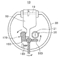
図13は第4の変形例を模式的に示した説明図である。この図には上方から見た状態が示されている。第4の変形例に係る飲料容器1Dは、ストローキャップ9Dをロックするためのロック機構15Dが設けられており、そのロック機構15Dが持っているロック部材16Dの回転軸線方向が第2及び第3の変形例とは異なっている。即ち、ロック部材16Dは、その回転軸線方向が飲料容器1Dの上下方向に設定されていて、図示のロック位置から解除位置まで回転動作可能な状態でストローアダプタ3Dに取り付けられている。ロック機構15Dは、ロック部材16Dがロック位置にあるときに、ロック部材16Dとストローキャップ9Dとを噛み合わせる拘束部17Dと、ロック部材16Dをロック位置側に付勢するリターンばね18Dとを備えている。ロック部材16Dにはその回転中心部から右方向に延びる伝達部材30Dが一体に設けられている。従って、飲料容器1Dは、ロック部材16Dが矢印方向に回転して解除位置に達すると、伝達部材30Dが開閉弁20の弁体21を弾性変形させることができる。そして、ロック部材16Dが解除位置まで動作することによって、ストローキャップ9Dの拘束が解かれるので、ストローキャップ9Dを開位置の側に動作させることができる。ストローキャップ9Dが開位置に位置した状態でロック部材16Dはリターンばね18Dにより図示の位置に戻されるので、伝達部材30Dが開閉弁20から離間する。これにより、伝達部材30Dによる開閉弁20の弁体21に対する押し込み操作が解除されるため、開閉弁20は開状態から閉状態へ自動的に復帰できる。この変形例においては、ロック部材16Dがストローキャップ9D側に設けられるように更に変更することも可能ある。
FIG. 13 is an explanatory view schematically showing a fourth modification. This figure shows the state seen from above. The beverage container 1D according to the fourth modification is provided with a
図14は第5の変形例を模式的に示した説明図である。図示するように、第5の変形例に係る飲料容器1Eには、ストローキャップ9Eをロックするためのロック機構15Eが設けられており、そのロック機構15Eは図示のロック位置と解除位置との間でスライド動作可能な状態でストローアダプタ3Eに取り付けられたロック部材16Eを有している。ロック機構15Eは、ロック部材16Eがロック位置にあるときに、ロック部材16Eとストローキャップ9Eとを噛み合わせる拘束部17Eと、ロック部材16Eをロック位置側に付勢するリターンばね18Eとを備えている。開閉弁20Eは、上記各例とは異なり弁体21Eがストローアダプタ3Eから長く延びており、ロック部材16Eと一体移動可能にロック部材16Eに取り付けられている。そして、ストローアダプタ8Eには弁体21Eに隣接するようにして上方に突出する伝達部材30Eが設けられている。従って、飲料容器1Eは、ロック部材16Eが矢印方向に動作されて解除位置に達すると、ロック部材16Eとともに弁体21Eが移動して伝達部材30Eに突き当たるので、弁体21Eに対する押し込み操作が伝達部材30Eにて加えられ弁体21Eが弾性変形する。そして、ロック部材16Eが解除位置まで動作することによって、ストローキャップ9Eの拘束が解かれるので、ストローキャップ9Eを開位置の側に動作させることができる。ストローキャップ9Eが開位置に位置した状態で、ロック部材16Eはリターンばね18Eにより、又はロック部材16Eがストローキャップ9Eとともに上方へ移動さうることにより、伝達部材30Eが開閉弁20Eから離間する。これにより、伝達部材30Eによる弁体21Eに対する押し込み操作が解除されるため、開閉弁20Eは開状態から閉状態へ自動的に復帰できる。
FIG. 14 is an explanatory view schematically showing a fifth modification. As shown in the figure, the
図1〜図9に示した形態及び図10〜図14に示した各変形例に係る開閉弁は、弾性材料で構成された弁体を有し、その弁体の弾性変形を利用して閉状態と開状態とを変更するものである。しかしながら、図15に示すような構造の開閉弁により本発明を実施することもできる。図15は開閉弁の他の形態を示した説明図である。図示の開閉弁50は、容器本体2の内外を仕切る仕切板51と、その仕切板51と密着しながら図の左右方向に移動可能な状態で設けられた移動弁体52と、移動弁体52を図示の位置側に付勢するリターンばね53と、移動弁体53の移動を規制するストッパ54とを備えている。仕切板51の中央には移動弁体52にて塞がれ得る大きさの貫通孔51aが形成されている。また、移動弁体52には仕切板51の貫通孔51aよりも大きな貫通孔52aが形成されている。
The on-off valve according to the embodiments shown in FIGS. 1 to 9 and the modifications shown in FIGS. 10 to 14 has a valve body made of an elastic material, and is closed using the elastic deformation of the valve body. The state and the open state are changed. However, the present invention can also be implemented by an on-off valve having a structure as shown in FIG. FIG. 15 is an explanatory view showing another embodiment of the on-off valve. The illustrated on-off
図示の状態においては、仕切板51の貫通孔51aの位置と移動弁体52の貫通孔52aの位置とが互いにずれていて、仕切板51の貫通孔51aが移動弁体52にて塞がれている。そのため、開閉弁50は容器本体2の内外を閉鎖する閉状態となる。図示の状態から、移動弁体52が矢印方向に押し込み操作されると、各貫通孔51a、52aの位置が一致するため容器本体2の内外が連通して閉状態から開状態へ移行する。開状態に移行した状態で移動弁体52に対する押し込み操作が解除されると、移動弁体52がリターンばね53により図示の位置に復帰する。そのため、開閉弁50は押し込み操作の解除とともに開状態から閉状態に自動的に復帰できる。
In the illustrated state, the position of the through
上述した図1〜図9に示した形態及び図10〜図14に示した各変形例に係る開閉弁を図15に示した開閉弁50に置き換えても、その開閉弁50に対して各伝達部材にて所定操作である押し込み操作を加えることができる。このため、開閉弁50を利用した飲料容器は上記形態及び各変形例の飲料容器と同等に機能する。
1 to 9 and the on / off valve according to each modification shown in FIGS. 10 to 14 are replaced with the on / off
開閉弁に加える所定操作は開閉弁の構成に応じて適宜に決まるものである。従って、例えば何らかの部材を引っ張ることにより閉状態から開状態へ移行する開閉弁の場合は引っ張り操作が所定操作に該当する。また、何らかの部材を回転させることにより閉状態から開状態へ移行する開閉弁の場合は回転操作が所定操作に該当する。 The predetermined operation applied to the on-off valve is appropriately determined according to the configuration of the on-off valve. Therefore, for example, in the case of an on-off valve that shifts from a closed state to an open state by pulling some member, the pulling operation corresponds to the predetermined operation. In the case of an on-off valve that shifts from a closed state to an open state by rotating some member, the rotation operation corresponds to a predetermined operation.
1、1A〜1E 飲料容器
2 容器本体
2a 開口部
3、3A〜3E ストローアダプタ
6 ストロー
7 吸い口部
9、9A〜9E ストローキャップ
10 支持軸
15、15A〜15E ロック機構
16、16A〜16E ロック部材
20、20E、50 開閉弁
21、21E 弁体
25 板部
26 保持部
27 スリット
30、30A〜30E 伝達部材
DESCRIPTION OF
Claims (6)
前記ストローを隠す閉位置と前記ストローを露出させる開位置との間で動作可能な状態で前記ストローアダプタに取り付けられたストローキャップと、
前記ストローキャップを前記閉位置にロックするロック位置と、そのロックを解除する解除位置との間で動作可能なロック部材と、
前記容器本体の内外を閉鎖する閉状態と前記容器本体の内外を連通する開状態との間で状態を変更でき、所定操作を受け付けることにより前記閉状態から前記開状態へ移行するとともに、前記所定操作が解除されることにより前記開状態から前記閉状態へ復帰する開閉弁と、
前記ロック位置から前記解除位置へ向かう前記ロック部材の動作を前記開閉弁に対する前記所定操作として伝達し、かつ前記ストローキャップが前記開位置に位置した状態で前記開閉弁に対する前記所定操作が解除されるように前記開閉弁から離間する伝達部材と、
を備えることを特徴とするストロー付き飲料容器。 A straw body having a container body having an opening and a straw adapter attached to the container body so as to close the opening, wherein a straw for inhaling a beverage in the container body is attached to the straw adapter. In beverage containers with
A straw cap attached to the straw adapter in an operable state between a closed position for hiding the straw and an open position for exposing the straw;
A lock member operable between a lock position for locking the straw cap in the closed position and a release position for releasing the lock;
The state can be changed between a closed state in which the inside and outside of the container body is closed and an open state in which the inside and outside of the container body are communicated, and when the predetermined operation is accepted, the state is changed from the closed state to the open state, and the predetermined state An on-off valve that returns from the open state to the closed state when the operation is released;
The operation of the lock member from the lock position to the release position is transmitted as the predetermined operation on the on-off valve, and the predetermined operation on the on-off valve is released in a state where the straw cap is located at the open position. A transmission member spaced from the on-off valve,
A beverage container with a straw, comprising:
前記ロック部材は、前記ロック位置と前記解除位置との間で動作可能な状態で前記ストローキャップに設けられ、
前記伝達部材は、前記ロック部材と一体移動可能な状態で前記ロック部材に設けられている、請求項1〜5のいずれか一項に記載の飲料容器。 The straw cap can be operated between the closed position and the open position by being attached to the straw adapter rotatably via a support shaft,
The lock member is provided on the straw cap in a state operable between the lock position and the release position;
The beverage container according to any one of claims 1 to 5, wherein the transmission member is provided on the lock member so as to be movable together with the lock member.
Priority Applications (7)
| Application Number | Priority Date | Filing Date | Title |
|---|---|---|---|
| JP2009208000A JP5301397B2 (en) | 2009-09-09 | 2009-09-09 | Beverage container with straw |
| TW099130612A TWI501903B (en) | 2009-09-09 | 2010-09-09 | Drink container with straw |
| EP10815425A EP2476628A4 (en) | 2009-09-09 | 2010-09-09 | CONTAINER OF BEVERAGE WITH STRAW |
| KR1020127008151A KR101696503B1 (en) | 2009-09-09 | 2010-09-09 | Beverage container with straw |
| HK12107669.1A HK1167248B (en) | 2009-09-09 | 2010-09-09 | Beverage container with straw |
| PCT/JP2010/065539 WO2011030830A1 (en) | 2009-09-09 | 2010-09-09 | Beverage container with straw |
| CN201080040047.0A CN102482010B (en) | 2009-09-09 | 2010-09-09 | Beverage container with straw |
Applications Claiming Priority (1)
| Application Number | Priority Date | Filing Date | Title |
|---|---|---|---|
| JP2009208000A JP5301397B2 (en) | 2009-09-09 | 2009-09-09 | Beverage container with straw |
Publications (2)
| Publication Number | Publication Date |
|---|---|
| JP2011057250A JP2011057250A (en) | 2011-03-24 |
| JP5301397B2 true JP5301397B2 (en) | 2013-09-25 |
Family
ID=43945386
Family Applications (1)
| Application Number | Title | Priority Date | Filing Date |
|---|---|---|---|
| JP2009208000A Active JP5301397B2 (en) | 2009-09-09 | 2009-09-09 | Beverage container with straw |
Country Status (1)
| Country | Link |
|---|---|
| JP (1) | JP5301397B2 (en) |
Families Citing this family (11)
| Publication number | Priority date | Publication date | Assignee | Title |
|---|---|---|---|---|
| JP5922409B2 (en) | 2011-05-31 | 2016-05-24 | ピジョン株式会社 | Beverage container |
| US8690026B2 (en) * | 2011-10-25 | 2014-04-08 | David S. Smith America, Inc. | Fluid dispensing assembly |
| WO2013072972A1 (en) * | 2011-11-18 | 2013-05-23 | ピジョン株式会社 | Beverage container |
| US8689989B2 (en) * | 2012-02-28 | 2014-04-08 | Thermos L.L.C. | Drink bottle and lid with button release at back of lid |
| US9150335B2 (en) | 2012-02-28 | 2015-10-06 | Thermos L.L.C. | Beverage container system with button release for lid |
| JP6150131B2 (en) * | 2014-01-31 | 2017-06-21 | 株式会社吉野工業所 | Container for preventing ejection of contents |
| JP6566556B2 (en) * | 2015-07-31 | 2019-08-28 | 株式会社リッチェル | Beverage container |
| CN105438624B (en) * | 2015-12-28 | 2017-09-15 | 新文越婴童用品(深圳)有限公司 | A kind of cap for container and its container |
| CN105476401B (en) * | 2016-01-12 | 2017-06-23 | 广州市新力实业有限公司 | A kind of cup cover for water cup and suction nozzle and its method for sealed sucktion nozzle steam vent |
| JP6784567B2 (en) * | 2016-10-26 | 2020-11-11 | 株式会社リッチェル | Beverage container |
| JP6957030B2 (en) * | 2018-11-12 | 2021-11-02 | コンビ株式会社 | Beverage container and cap assembly |
Family Cites Families (5)
| Publication number | Priority date | Publication date | Assignee | Title |
|---|---|---|---|---|
| JPH044576Y2 (en) * | 1986-02-15 | 1992-02-10 | ||
| NL1016109C2 (en) * | 2000-09-05 | 2002-03-11 | Vacu Vin Innovations Ltd | Valve. |
| JP2004042982A (en) * | 2002-07-15 | 2004-02-12 | Richell Corp | Beverage container |
| JP4699096B2 (en) * | 2005-06-06 | 2011-06-08 | ピジョン株式会社 | Beverage container |
| JP3136174U (en) * | 2007-08-01 | 2007-10-18 | パール金属株式会社 | Beverage container |
-
2009
- 2009-09-09 JP JP2009208000A patent/JP5301397B2/en active Active
Also Published As
| Publication number | Publication date |
|---|---|
| JP2011057250A (en) | 2011-03-24 |
Similar Documents
| Publication | Publication Date | Title |
|---|---|---|
| JP5301397B2 (en) | Beverage container with straw | |
| WO2011030830A1 (en) | Beverage container with straw | |
| JP7472040B2 (en) | Container lids and containers with button release and lock | |
| CN101472805B (en) | Beverage container | |
| JP6027647B1 (en) | Cap unit and beverage container | |
| JP5301398B2 (en) | Beverage container with straw | |
| JP2005193944A (en) | Stopper of drink container | |
| CN104417958A (en) | Beverage container | |
| JP2017154780A (en) | Cap unit and beverage container | |
| CN109071073A (en) | Resealable container | |
| JP2007176537A (en) | Cap for beverage container, and beverage container | |
| JP2021080026A (en) | Plug and beverage container | |
| JP2018008714A (en) | Cap unit and beverage container | |
| JP2017007742A (en) | Cap unit and beverage container | |
| JP2022084841A (en) | Box device for vehicle | |
| JP6346785B2 (en) | Plug body and container provided with the plug body | |
| JP2009023712A (en) | Beverage container lid | |
| JP6466387B2 (en) | Cap unit and beverage container | |
| JP6190676B2 (en) | Infant beverage container | |
| HK1167248B (en) | Beverage container with straw | |
| JP3171651U (en) | Beverage container stopper and beverage container having the same | |
| JP3201676U (en) | Beverage container | |
| JP3150119U (en) | Beverage container stopper and beverage container having the same | |
| JP2019006491A (en) | Cap unit and container with cap | |
| JP3588341B2 (en) | Granular container |
Legal Events
| Date | Code | Title | Description |
|---|---|---|---|
| A621 | Written request for application examination |
Free format text: JAPANESE INTERMEDIATE CODE: A621 Effective date: 20120910 |
|
| TRDD | Decision of grant or rejection written | ||
| A01 | Written decision to grant a patent or to grant a registration (utility model) |
Free format text: JAPANESE INTERMEDIATE CODE: A01 Effective date: 20130611 |
|
| A61 | First payment of annual fees (during grant procedure) |
Free format text: JAPANESE INTERMEDIATE CODE: A61 Effective date: 20130619 |
|
| R150 | Certificate of patent or registration of utility model |
Ref document number: 5301397 Country of ref document: JP Free format text: JAPANESE INTERMEDIATE CODE: R150 Free format text: JAPANESE INTERMEDIATE CODE: R150 |
|
| R250 | Receipt of annual fees |
Free format text: JAPANESE INTERMEDIATE CODE: R250 |
|
| R250 | Receipt of annual fees |
Free format text: JAPANESE INTERMEDIATE CODE: R250 |
|
| R250 | Receipt of annual fees |
Free format text: JAPANESE INTERMEDIATE CODE: R250 |
|
| R250 | Receipt of annual fees |
Free format text: JAPANESE INTERMEDIATE CODE: R250 |
|
| R250 | Receipt of annual fees |
Free format text: JAPANESE INTERMEDIATE CODE: R250 |
|
| R250 | Receipt of annual fees |
Free format text: JAPANESE INTERMEDIATE CODE: R250 |
|
| R250 | Receipt of annual fees |
Free format text: JAPANESE INTERMEDIATE CODE: R250 |
|
| R250 | Receipt of annual fees |
Free format text: JAPANESE INTERMEDIATE CODE: R250 |
|
| R250 | Receipt of annual fees |
Free format text: JAPANESE INTERMEDIATE CODE: R250 |
|
| R250 | Receipt of annual fees |
Free format text: JAPANESE INTERMEDIATE CODE: R250 |