JP5297731B2 - Recycled casting sand manufacturing method - Google Patents
Recycled casting sand manufacturing method Download PDFInfo
- Publication number
- JP5297731B2 JP5297731B2 JP2008231954A JP2008231954A JP5297731B2 JP 5297731 B2 JP5297731 B2 JP 5297731B2 JP 2008231954 A JP2008231954 A JP 2008231954A JP 2008231954 A JP2008231954 A JP 2008231954A JP 5297731 B2 JP5297731 B2 JP 5297731B2
- Authority
- JP
- Japan
- Prior art keywords
- sand
- recovered
- polishing
- additive
- weight
- Prior art date
- Legal status (The legal status is an assumption and is not a legal conclusion. Google has not performed a legal analysis and makes no representation as to the accuracy of the status listed.)
- Active
Links
Images


Classifications
-
- B—PERFORMING OPERATIONS; TRANSPORTING
- B07—SEPARATING SOLIDS FROM SOLIDS; SORTING
- B07B—SEPARATING SOLIDS FROM SOLIDS BY SIEVING, SCREENING, SIFTING OR BY USING GAS CURRENTS; SEPARATING BY OTHER DRY METHODS APPLICABLE TO BULK MATERIAL, e.g. LOOSE ARTICLES FIT TO BE HANDLED LIKE BULK MATERIAL
- B07B4/00—Separating solids from solids by subjecting their mixture to gas currents
- B07B4/08—Separating solids from solids by subjecting their mixture to gas currents while the mixtures are supported by sieves, screens, or like mechanical elements
-
- B—PERFORMING OPERATIONS; TRANSPORTING
- B22—CASTING; POWDER METALLURGY
- B22C—FOUNDRY MOULDING
- B22C5/00—Machines or devices specially designed for dressing or handling the mould material so far as specially adapted for that purpose
- B22C5/18—Plants for preparing mould materials
Description
本発明は鋳型から回収された回収砂からの再生鋳物砂の製造方法に関する。 The present invention relates to a method for producing reclaimed foundry sand from recovered sand recovered from a mold.
鋳型に用いた鋳物砂は、鋳型を粉砕(型ばらし)して得た回収砂に再生処理を施して再利用されることがある。回収砂の再生方法には、古くより湿式再生法、加熱式再生法、乾式再生法等各種の方法が提案(例えば非特許文献1)され、実施されている。また、特許文献1には、所定の回収砂に加熱処理を施した後、乾式研磨処理を施す鋳物砂の再生方法が開示されている。特許文献2は乾式再生法であって、鋳物砂の中に微細粒体を添加した後に再生する方法を開示している。
The foundry sand used for the mold may be reused by subjecting the recovered sand obtained by pulverizing (separating) the mold to a regeneration process. Various methods such as a wet regeneration method, a heating regeneration method, and a dry regeneration method have been proposed and practiced as a method for reclaiming recovered sand since ancient times (for example, Non-Patent Document 1). Further, Patent Document 1 discloses a method for regenerating foundry sand in which predetermined recovered sand is subjected to heat treatment and then subjected to dry polishing.
従来の技術の湿式再生法では汚水処理装置を必要とし、そのために設備費がかかり、又再生費もかさむ。また再生処理後は砂を乾燥させる必要もある。更には加熱式再生法では燃焼設備、空冷設備を必要とし、多大なエネルギーコストがかかり、更には排ガスの処理をする必要がある。乾式再生法では、遠心力を利用して砂粒間に摩擦を与え砂粒表面に付着している粘結剤等を除く方法が現在一般的に普及している。しかしながら、この方法では、再生効率を高めようとすると、砂の破砕、細粒化などにより歩留まりが低下し、回収砂1トン当たりの動力原単位も大となる。 Conventional wet regeneration methods require a sewage treatment apparatus, which incurs equipment costs and increases regeneration costs. It is also necessary to dry the sand after the regeneration process. Furthermore, the heating regeneration method requires a combustion facility and an air cooling facility, which requires a large energy cost and further needs to treat exhaust gas. In the dry regeneration method, a method in which a centrifugal force is used to cause friction between sand particles and remove a binder or the like adhering to the surface of the sand particles is now widely used. However, in this method, if the regeneration efficiency is to be increased, the yield decreases due to sand crushing, fine graining, etc., and the power unit per ton of recovered sand increases.
また、砂の破砕を防ぎ、再生歩留まりを向上させる、即ち廃棄物の低減のため、耐破砕性の高い人工セラミック砂が開発され実用化されているが、砂粒表面に強固に付着している粘結剤のみを取り除き、再生効率を高めるためには、再生機を多段に重ねる必要があり、動力原単位が更にかかるという課題がある。 Moreover, artificial ceramic sand with high crush resistance has been developed and put into practical use in order to prevent sand crushing and improve the recovery yield, that is, to reduce waste. In order to remove only the binder and increase the regeneration efficiency, it is necessary to stack the regenerators in multiple stages, and there is a problem that the power consumption is further increased.
こうした背景から、特許文献2には、乾式再生法において、鋳物砂の中に微細粒体を添加した後に再生する方法が開示されている。しかしながら、本微細粒体を除去する工程が必要であり、工程が煩雑になる。また、本微細粒体の除去が不十分な場合、鋳型強度が低下する可能性がある。
Against this background,
また、こうした背景から、鋳物砂の再生については、多大な設備を用いず、簡易な方法による効率的な再生鋳物砂の製造方法の提案が期待されている。 From such a background, it is expected to propose an efficient method for producing reclaimed foundry sand by a simple method without using a large amount of equipment for reclaiming foundry sand.
本発明は、不純物の除去率が高く鋳物品質及び鋳型強度が向上できる再生鋳物砂の製造方法を提供する。 The present invention provides a method for producing reclaimed foundry sand with a high impurity removal rate and improved casting quality and mold strength.
本発明は、25℃での表面張力が35mN/m以下で且つ1気圧での沸点が150℃以上の液体からなる添加剤(A)〔以下添加剤(A)という〕の存在下で回収砂の研磨処理を行う工程(I)を有する、再生鋳物砂の製造方法に関する。 In the present invention, recovered sand is present in the presence of an additive (A) (hereinafter referred to as additive (A)) comprising a liquid having a surface tension at 25 ° C. of 35 mN / m or less and a boiling point at 1 atm of 150 ° C. or more. It is related with the manufacturing method of reclaimed foundry sand which has process (I) which performs the grinding | polishing process of this.
なお、本発明において、表面張力はWilhelmy法によるものであり、具体的には、Wilhelmy法を採用した自動表面張力計を用いて測定することができる。 In the present invention, the surface tension is determined by the Wilhelmy method, and specifically, it can be measured using an automatic surface tension meter employing the Wilhelmy method.
また、本発明は、上記本発明の製造方法により得られた再生鋳物砂を用いる鋳型の製造方法に関する。 Moreover, this invention relates to the manufacturing method of the casting_mold | template using the reclaimed foundry sand obtained by the manufacturing method of the said invention.
本発明の再生鋳物砂の製造方法によれば、効率よく残留有機分を除去した鋳物砂を得ることができる。また、本発明によって再生された鋳物砂は、鋳型強度に優れた鋳型を提供することができる。 According to the method for producing reclaimed foundry sand of the present invention, foundry sand from which residual organic components have been efficiently removed can be obtained. The foundry sand regenerated by the present invention can provide a mold having excellent mold strength.
本発明で使用する回収砂とは、「図解 鋳造用語辞典」(社団法人日本鋳造工学会編、2003年4月28日、日刊工業新聞社発行)に回収砂として記載されている通りである。 The recovered sand used in the present invention is as described as recovered sand in “Illustration casting terminology dictionary” (edited by the Japan Foundry Engineering Society, April 28, 2003, published by Nikkan Kogyo Shimbun).
具体的には、本発明で使用する回収砂は、珪砂、ジルコン砂、クロマイト砂、合成ムライト砂やSiO2/Al2O3系の鋳物砂、SiO2/MgO系の鋳物砂、スラグ由来の鋳物砂などの鋳物砂に、粘結剤を使用して造型した後、解枠(型ばらし)して得られた回収砂ないし余剰砂(以下、合わせて回収砂という)である。 Specifically, the recovered sand used in the present invention is derived from silica sand, zircon sand, chromite sand, synthetic mullite sand, SiO 2 / Al 2 O 3 casting sand, SiO 2 / MgO casting sand, slag This is recovered sand or surplus sand (hereinafter collectively referred to as recovered sand) obtained by forming a casting sand such as foundry sand using a binder and then releasing the frame (demolding).
また、本発明で使用する回収砂を再生処理する際には、回収砂だけでなく新砂を含んでいても構わない。本発明における効果は、回収砂の量に応じて得ることができる。特に、回収砂が50重量%以上含まれていれば、充分な効果を得ることが出来る。 Further, when the recovered sand used in the present invention is regenerated, it may contain not only recovered sand but also fresh sand. The effect in the present invention can be obtained according to the amount of recovered sand. In particular, if the recovered sand is contained in an amount of 50% by weight or more, a sufficient effect can be obtained.
本発明は、より残留樹脂除去率の向上と廃棄物低減の観点から、回収砂は、合成ムライト砂やSiO2/Al2O3系の鋳物砂、SiO2/MgO系の鋳物砂、スラグ由来の鋳物砂などの人工セラミック砂由来の回収砂が好ましい。 In the present invention, the recovered sand is derived from synthetic mullite sand, SiO 2 / Al 2 O 3 casting sand, SiO 2 / MgO casting sand, and slag from the viewpoint of further improving the residual resin removal rate and reducing waste. Recovered sand derived from artificial ceramic sand such as foundry sand is preferred.
人工セラミック砂とは、珪砂、ジルコンサンド、クロマイトサンド等の天然より産出する鋳物砂でなく、人工的に金属酸化物の成分を調整し、溶融若しくは焼結した鋳物砂のことを表す。耐破砕性が高く、より廃棄物が低減できる観点から、SiO2とAl2O3を合計で80重量%以上含有し、かつAl2O3/SiO2の重量比率が1〜15である鋳物砂が好ましい。また、ムライト、α−アルミナ、γ−アルミナの内少なくともいずれか一つの結晶相を持つものが好ましい。 Artificial ceramic sand refers to casting sand which is not a foundry sand produced from nature such as quartz sand, zircon sand, chromite sand, etc., but which is obtained by artificially adjusting the components of metal oxide and melting or sintering. From the viewpoint of high crush resistance and further reduction of waste, a casting containing a total of 80% by weight of SiO 2 and Al 2 O 3 and a weight ratio of Al 2 O 3 / SiO 2 of 1 to 15 Sand is preferred. Further, those having at least one crystal phase of mullite, α-alumina, and γ-alumina are preferable.
また、本発明は、より効果が発現される観点から、球状鋳物砂由来の回収砂に対して著しい効果を示す。球状鋳物砂の球形度としては、球形度が0.88以上、更に0.92以上、より更に0.95以上、特に0.99以上である鋳物砂由来の回収砂がより好ましい。 Moreover, this invention shows a remarkable effect with respect to the recovery sand derived from spherical casting sand from a viewpoint from which an effect is expressed more. As the sphericity of the spherical casting sand, recovered sand derived from foundry sand having a sphericity of 0.88 or more, further 0.92 or more, more preferably 0.95 or more, and particularly 0.99 or more is more preferable.
球形度は、光学顕微鏡またはデジタルスコープ(例えば、キーエンス社製、VH−8000型)により得られた該粒子の像(写真)を画像解析することにより、該粒子の粒子投影断面の面積及び該断面の周囲長を求め、次いで、〔粒子投影断面の面積(mm2)と同じ面積の真円の円周長(mm)〕/〔粒子投影断面の周囲長(mm)〕を計算し、任意の50個の球状鋳物砂粒子につき、それぞれ得られた値を平均して求めることができる。 The sphericity is determined by analyzing an image (photograph) of the particle obtained by an optical microscope or a digital scope (for example, VH-8000, manufactured by Keyence Corporation), thereby analyzing the area of the particle projection cross section of the particle and the cross section. Next, calculate [circumferential length (mm) of a perfect circle having the same area as the projected particle cross section (mm 2 )] / [perimeter of the projected particle cross section (mm)] The obtained values can be averaged for 50 spheroidal sand particles.
球形鋳物砂は、鋳型にした際の充填率が高く、鋳型強度が高いという利点があるが、乾式機械再生においては、砂粒子間の摩擦が小さいため再生効率が良好ではなかった。しかし本発明により、球状鋳物砂のメリットを生かしかつ効率的な再生が可能となる。 Spherical foundry sand has the advantages of a high filling rate when formed into a mold and high mold strength, but in dry machine regeneration, the friction between sand particles is small, so the regeneration efficiency is not good. However, according to the present invention, it is possible to recycle efficiently by taking advantage of the advantages of the spherical casting sand.
このような球状鋳物砂は、例えば、耐火原料スラリーをスプレードライによって球状に造粒した後、焼成する方法や、耐火原料を溶融させノズルからエアと共に噴出させ球状化する方法、耐火物粒子をキャリアーガスに分散させ火炎中で溶融させ球状化する方法があり、例えば特開昭61−63333号公報や特開2003−251434号公報や特開2005−193267号公報、特開2004−202577号公報に示されるような方法により製造されうる。 Such spheroidal sands include, for example, a method in which a refractory raw material slurry is granulated into a spherical shape by spray drying and then fired, a method in which a refractory raw material is melted and jetted together with air from a nozzle, and a refractory particle in a carrier There is a method of dispersing in a gas, melting in a flame and spheroidizing, for example, in JP-A-61-63333, JP-A-2003-251434, JP-A-2005-193267, and JP-A-2004-202577. It can be manufactured by the method as shown.
本発明において上記人工セラミック砂及び/又は上記球状鋳物砂由来の回収砂が回収砂中に50重量%以上含まれているのが好ましい。 In the present invention, it is preferable that 50% by weight or more of the artificial ceramic sand and / or the recovered sand derived from the spherical cast sand is contained in the recovered sand.
本発明で回収砂は、本発明の効果である、回収砂の残留有機分を効率よく除去する観点から、粘結剤としては、有機粘結剤が好ましい。有機粘結剤としては、例えば、アルカリフェノール樹脂、フラン樹脂、熱硬化性フェノール樹脂(シェルモールド)、ウレタン樹脂が挙げられる。 In the present invention, the recovered sand is preferably an organic binder from the viewpoint of efficiently removing the residual organic content of the recovered sand, which is an effect of the present invention. Examples of the organic binder include alkali phenol resin, furan resin, thermosetting phenol resin (shell mold), and urethane resin.
また、鋳物砂として人工セラミック砂を用い、粘結剤としてアルカリ性の粘結剤を用いて硬化させた鋳型からの回収砂においては、砂が硬く、且つ残留有機分が砂と比べ柔らかく、更に強固に付着しており、再生が難しかったが、本発明は、このような回収砂に対しても十分な効果が発揮される。 Also, in the recovered sand from the mold that is hardened using artificial ceramic sand as the foundry sand and alkaline binder as the binder, the sand is hard and the residual organic content is softer and stronger than the sand. Although it is difficult to regenerate, the present invention is sufficiently effective for such recovered sand.
アルカリフェノール樹脂としては、例えばフェノール、クレゾール、レゾルシノール、ビスフェノールA、その他置換フェノールを含めたフェノール類を原料として、アルカリ性触媒のもとアルデヒド化合物等と反応させることによって得られるフェノール樹脂が挙げられる。アルカリ触媒としては、水酸化リチウム、水酸化ナトリウム、水酸化カリウム等のアルカリ金属の水酸化物、水酸化カルシウム、水酸化マグネシウム、水酸化ベリリウム等アルカリ土類金属の水酸化物、アミン化合物、及びこれらの混合物が挙げられる。一般には、フェノール類に対するアルカリ触媒のモル数が、好ましくは0.05〜4倍モルであり、より好ましくは0.1〜3倍モルである。 Examples of the alkali phenol resin include phenol resins obtained by reacting phenol, cresol, resorcinol, bisphenol A, and other substituted phenols as raw materials with an aldehyde compound or the like under an alkaline catalyst. Alkali catalysts include alkali metal hydroxides such as lithium hydroxide, sodium hydroxide and potassium hydroxide, alkaline earth metal hydroxides such as calcium hydroxide, magnesium hydroxide and beryllium hydroxide, amine compounds, and These mixtures are mentioned. In general, the number of moles of the alkali catalyst relative to the phenols is preferably 0.05 to 4 times, more preferably 0.1 to 3 times.
有機エステルとしては、γ−ブチロラクトン、プロピオンラクトン、ε−カプロラクトン、ギ酸エチル、エチレングリコールジアセテート、エチレングリコールモノアセテート、トリアセチン、アセト酢酸エチル等が挙げられる。 Examples of the organic ester include γ-butyrolactone, propionlactone, ε-caprolactone, ethyl formate, ethylene glycol diacetate, ethylene glycol monoacetate, triacetin, and ethyl acetoacetate.
本発明の製造方法は、添加剤(A)の存在下で回収砂の研磨処理を行う工程(I)を有する。 The production method of the present invention has a step (I) of polishing the recovered sand in the presence of the additive (A).
添加剤(A)は、25℃での表面張力が35mN/m以下の液体であり、且つ、1気圧での沸点が150℃以上の液体である。 The additive (A) is a liquid having a surface tension at 25 ° C. of 35 mN / m or less and a boiling point at 1 atm of 150 ° C. or more.
添加剤(A)を25℃での表面張力を35mN/m以下の液体と規定する技術的意義は、研磨処理の際に生じるダストを再生砂に付着しにくくするためである。また、添加剤(A)を1気圧での沸点が150℃以上の液体と規定する技術的意義は、添加剤(A)が集塵操作の時にダストよりも早く消失しないようにするためである。 The technical significance of defining the additive (A) as a liquid having a surface tension at 25 ° C. of 35 mN / m or less is to make it difficult for the dust generated during the polishing process to adhere to the reclaimed sand. Further, the technical significance of defining the additive (A) as a liquid having a boiling point of 150 ° C. or higher at 1 atm is to prevent the additive (A) from disappearing earlier than dust during the dust collection operation. .
添加剤(A)の25℃での表面張力は、研磨処理の際に生じるダストを再生砂に付着しにくくする観点から、好ましくは15〜35mN/mであり、より好ましくは15〜33mN/mである。また、添加剤(A)の1気圧での沸点は、添加剤(A)が集塵操作の時にダストよりも早く消失しないようにする観点から、好ましくは150〜400℃であり、より好ましくは165〜400℃である。なお、400℃以下で分解点を持つようなものは、少なくとも150℃で液体状態であれば、本発明の添加剤(A)に含まれる。 The surface tension at 25 ° C. of the additive (A) is preferably 15 to 35 mN / m, more preferably 15 to 33 mN / m, from the viewpoint of making it difficult for the dust generated during the polishing process to adhere to the recycled sand. It is. In addition, the boiling point of the additive (A) at 1 atm is preferably 150 to 400 ° C., more preferably from the viewpoint of preventing the additive (A) from disappearing earlier than dust during the dust collection operation. 165 to 400 ° C. In addition, what has a decomposition point below 400 degreeC will be contained in the additive (A) of this invention, if it is a liquid state at least at 150 degreeC.
添加剤(A)としては、シリコーンオイル、炭素数8〜18のアルコール、炭素数8〜18のカルボン酸、炭素数1〜8のアルキル基を有するアルキルシリケート及びその低縮合物、並びに、炭素数8〜18のアルキル基を有するポリオキシアルキレンアルキルエーテルの中から選ばれる1種以上が好ましい。 As the additive (A), silicone oil, alcohol having 8 to 18 carbon atoms, carboxylic acid having 8 to 18 carbon atoms, alkyl silicate having an alkyl group having 1 to 8 carbon atoms and a low condensate thereof, and carbon number One or more selected from polyoxyalkylene alkyl ethers having 8 to 18 alkyl groups are preferred.
本発明に用いられるシリコーンオイルとしては、ジメチルシリコーンオイル、メチルハイドロジェンシリコーンオイル、メチルフェニルシリコーンオイル、環状ジメチルシリコーンオイル、アミノ変性シリコーンオイル、ポリエーテル変性シリコーンオイル、アルキル変性シリコーンオイル、アルコール変性シリコーンオイル等が用いられる。好ましくはジメチルシリコーンオイルである。 Examples of the silicone oil used in the present invention include dimethyl silicone oil, methyl hydrogen silicone oil, methylphenyl silicone oil, cyclic dimethyl silicone oil, amino-modified silicone oil, polyether-modified silicone oil, alkyl-modified silicone oil, alcohol-modified silicone oil. Etc. are used. Preferred is dimethyl silicone oil.
シリコーンオイルの表面張力(25℃)は15〜25mN/mのものが好ましく、15〜22mN/mのものがより好ましい。シリコーンオイルは、粘度(25℃)が5〜300mm2/sのものが好ましく、5〜50mm2/sのものがより好ましい。また、安全性の観点から、シリコーンオイルの引火点が高い方が好ましく、100℃以上であることが好ましく、より好ましくは150℃以上、更に好ましくは200℃以上である。 The surface tension (25 ° C.) of the silicone oil is preferably 15 to 25 mN / m, more preferably 15 to 22 mN / m. The silicone oil preferably has a viscosity (25 ° C.) of 5 to 300 mm 2 / s, more preferably 5 to 50 mm 2 / s. From the viewpoint of safety, the higher flash point of the silicone oil is preferable, preferably 100 ° C. or higher, more preferably 150 ° C. or higher, and further preferably 200 ° C. or higher.
本発明に用いられる炭素数8〜18のアルコールとしては、直鎖脂肪族アルコール、分岐鎖脂肪族アルコール、不飽和脂肪族アルコール等が用いられ、表面張力(25℃)は15〜33mN/mのものが好ましい。炭素数8〜18のアルコールは、粘度(25℃)が2〜100mm2/sのものが好ましく、2〜50mm2/sのものがより好ましい。オレイルアルコール、オクタノールが好ましい。 As the alcohol having 8 to 18 carbon atoms used in the present invention, a linear aliphatic alcohol, a branched aliphatic alcohol, an unsaturated aliphatic alcohol or the like is used, and the surface tension (25 ° C.) is 15 to 33 mN / m. Those are preferred. The alcohol having 8 to 18 carbon atoms preferably has a viscosity (25 ° C.) of 2 to 100 mm 2 / s, and more preferably 2 to 50 mm 2 / s. Oleyl alcohol and octanol are preferred.
本発明に用いられる炭素数8〜18のカルボン酸としては、直鎖脂肪族カルボン酸、分岐鎖脂肪族カルボン酸、不飽和脂肪族カルボン酸等が用いられる。有機カルボン酸の表面張力(25℃)は15〜35mN/mのものが好ましい。炭素数8〜18のカルボン酸は、粘度(25℃)が2〜100mm2/sのものが好ましく、2〜50mm2/sのものがより好ましい。 As the carboxylic acid having 8 to 18 carbon atoms used in the present invention, straight chain aliphatic carboxylic acid, branched chain aliphatic carboxylic acid, unsaturated aliphatic carboxylic acid and the like are used. The surface tension (25 ° C.) of the organic carboxylic acid is preferably 15 to 35 mN / m. The carboxylic acid having 8 to 18 carbon atoms preferably has a viscosity (25 ° C.) of 2 to 100 mm 2 / s, more preferably 2 to 50 mm 2 / s.
本発明に用いられる炭素数1〜8のアルキル基を有するアルキルシリケートとしてはメチルシリケート、エチルシリケート等およびその低縮合物が挙げられる。低縮合物の縮合度は1〜15が好ましい。エチルシリケート及びその低縮合物が好ましい。 Examples of the alkyl silicate having an alkyl group having 1 to 8 carbon atoms used in the present invention include methyl silicate, ethyl silicate and the like and low condensates thereof. The degree of condensation of the low condensate is preferably 1-15. Ethyl silicate and its low condensates are preferred.
本発明に用いられる炭素数8〜18のアルキル基を有するポリオキシアルキレンアルキルエーテルは、オキシアルキレン基の平均付加モル数は0.5〜10、更に1〜5、より更に1〜3が好ましく、オキシアルキレン基として炭素数2〜4のオキシエチレン基、オキシプロピレン基及びオキシブチレン基が好ましい。 In the polyoxyalkylene alkyl ether having an alkyl group having 8 to 18 carbon atoms used in the present invention, the average added mole number of the oxyalkylene group is preferably 0.5 to 10, more preferably 1 to 5, still more preferably 1 to 3, As the oxyalkylene group, an oxyethylene group having 2 to 4 carbon atoms, an oxypropylene group, and an oxybutylene group are preferable.
また、安全性の観点から、これら添加剤(A)の引火点は高い方が好ましく、100℃以上であることが好ましく、より好ましくは150℃以上、更に好ましくは200℃以上である。 From the viewpoint of safety, the flash point of these additives (A) is preferably higher, preferably 100 ° C. or higher, more preferably 150 ° C. or higher, and further preferably 200 ° C. or higher.
添加剤(A)の研磨処理時の存在量は、回収砂100重量部に対して、残留樹脂分の除去効果発現の観点から、0.001重量部以上が好ましく、また、経済的観点及び効果が飽和する観点から0.2重量部以下が好ましい為、0.001〜0.2重量部、更に0.005〜0.1重量部、特に0.01〜0.05重量部が好ましい。 The amount of additive (A) present during the polishing treatment is preferably 0.001 part by weight or more from the viewpoint of the effect of removing the residual resin with respect to 100 parts by weight of recovered sand, and is also economical and advantageous. Is preferably 0.2 part by weight or less from the viewpoint of saturation of 0.001 to 0.2 part by weight, more preferably 0.005 to 0.1 part by weight, and particularly preferably 0.01 to 0.05 part by weight.
本発明では、回収砂の研磨処理を複数回行うことが好ましく、その少なくとも1つが添加剤(A)、好ましくはシリコーンオイルの存在下での研磨処理となる。すなわち、本発明の製造方法は、回収砂の研磨処理を少なくとも1回行う方法であって、研磨処理の少なくとも1つを添加剤(A)、好ましくはシリコーンオイルの存在下に行うものである。複数回の研磨を行うにあたり、添加剤(A)、好ましくはシリコーンオイルは、研磨処理(後述する水添研磨処理を含む。)にて回収砂から残留有機分を剥離する工程の前に回収砂に添加し最初の研磨を行っても良いが、不純物を分離・除去する効果の観点から、研磨処理時の回収砂に、添加剤(A)、好ましくはシリコーンオイルを添加してから研磨処理した方が好ましい。研磨処理時の添加量は、回収砂100重量部に対して、残留樹脂分の除去効果発現の観点から、0.001重量部以上が好ましく、また、経済的観点及び効果が飽和する観点から0.2重量部以下が好ましい為、0.001〜0.2重量部、更に0.005〜0.1重量部、特に0.01〜0.05重量部が好ましい。この場合、研磨処理時とは、研磨を行う直前や研磨を行っている間を意味する。更に、1回以上、研磨処理を行った後の砂に添加剤(A)、好ましくはシリコーンオイルを添加してから研磨処理した方がより好ましい。 In the present invention, it is preferable to polish the recovered sand a plurality of times, at least one of which is a polishing process in the presence of the additive (A), preferably silicone oil. That is, the production method of the present invention is a method in which the recovered sand is polished at least once, and at least one of the polishing processes is performed in the presence of the additive (A), preferably silicone oil. In performing the polishing a plurality of times, the additive (A), preferably the silicone oil, is recovered in the recovered sand before the step of removing the residual organic component from the recovered sand in a polishing process (including a hydrogenated polishing process described later). It may be added to the initial polishing, but from the viewpoint of the effect of separating and removing impurities, the additive (A), preferably silicone oil, is added to the collected sand during the polishing treatment and then the polishing treatment is performed. Is preferred. The addition amount at the time of polishing treatment is preferably 0.001 part by weight or more with respect to 100 parts by weight of the collected sand from the viewpoint of the effect of removing the residual resin, and is 0 from the viewpoint of saturation of the economic viewpoint and the effect. .2 parts by weight or less is preferable, so 0.001 to 0.2 parts by weight, 0.005 to 0.1 parts by weight, and particularly 0.01 to 0.05 parts by weight are preferable. In this case, the time of the polishing process means immediately before polishing or during polishing. Further, it is more preferable to add the additive (A), preferably silicone oil, to the sand after the polishing treatment at least once, and then perform the polishing treatment.
添加剤(A)の添加方法は、回収砂、若しくは研磨処理された回収砂に対して、連続式、バッチ式のいずれの方法で添加しても構わない。また、添加剤(A)をスプレー噴霧する方法や、ノズルから定量的に添加する方法をとる事ができる。添加剤と回収砂の混合は、専用の混合機を用いても構わないが、再生機内で混合されるため、特に専用の混合機を用いなくても構わない。また、添加剤(A)の存在下で研磨処理を行う再生機内に、スプレーやノズル等の添加手段を取り付け、そこから添加する方法でも構わない。場合により、シーケンス等で添加時期をコントロールし、適切な添加時期を調整することも出来る。 The additive (A) may be added to the recovered sand or the recovered sand that has been subjected to polishing by either a continuous method or a batch method. Moreover, the method of spraying an additive (A) and the method of adding quantitatively from a nozzle can be taken. For mixing the additive and the recovered sand, a dedicated mixer may be used. However, since mixing is performed in the regenerator, it is not particularly necessary to use a dedicated mixer. Moreover, the addition method, such as a spray and a nozzle, may be attached to the regenerator that performs the polishing process in the presence of the additive (A), and the addition may be performed from there. In some cases, the addition timing can be controlled by a sequence or the like, and an appropriate addition timing can be adjusted.
本発明の再生鋳物砂の製造方法によれば、従来の機械的に砂表面を処理する方法に比べ、効率よく残留有機分を除去した鋳物砂を得ることができる。また、本発明によって再生された鋳物砂は、鋳型強度に優れた鋳型を提供することができる。 According to the method for producing reclaimed foundry sand of the present invention, foundry sand from which residual organic components have been efficiently removed can be obtained as compared with the conventional method of mechanically treating the sand surface. The foundry sand regenerated by the present invention can provide a mold having excellent mold strength.
本発明の効果として、特に鋳型強度が特段に向上している理由は明らかではないが、添加剤(A)の存在によって、研磨処理で再生砂から剥離した付着物が、砂表面へ再付着するのを防いでいる結果、このような鋳型強度の顕著な差となって表れるものと考えられる。 As the effect of the present invention, the reason why the mold strength is particularly improved is not clear, but due to the presence of the additive (A), the deposits peeled off from the reclaimed sand by the polishing treatment are reattached to the sand surface. As a result of this, it is considered that such a remarkable difference in mold strength appears.
本発明において、回収砂の研磨処理は、鋳物砂同士の摩擦や、砂と再生機内部の部材(ローターや内壁、砥石)間の摩擦により行われる。 In the present invention, the recovered sand is polished by friction between the foundry sands and friction between the sand and members inside the regenerator (rotor, inner wall, grindstone).
工程(I)での研磨処理は、従来の鋳物砂の再生法における研磨処理、好ましくは乾式法に準じて行うことができ、例えば、噴気流型(砂粒を高速空気によって吹き飛ばして衝撃、摩擦を加え付着物を除去する方法)、垂直軸回転型及び水平軸回転型(回転体や羽根等によって砂粒を跳ね飛ばす、または攪拌する、更にはローターで加圧することにより砂粒相互の衝撃、摩擦が行われ、付着物を剥離除去する方法)、振動型(振動力によって砂粒に攪拌作用を与え、主として摩擦作用によって付着物を除去する方法)の各装置を用いた方法が挙げられる。 The polishing process in the step (I) can be performed according to a conventional polishing process in a reclaiming method of casting sand, preferably a dry process. For example, a jet stream type (impacts and friction is generated by blowing sand particles with high-speed air. Additive removal method), vertical axis rotation type and horizontal axis rotation type (impacts and friction between sand particles by jumping or stirring sand particles with a rotating body or blades, or by pressurizing with a rotor) For example, a method of peeling and removing deposits) and a method using a vibration type device (a method of stirring sand particles by vibration force and removing deposits mainly by friction).
添加剤(A)存在下の研磨処理においては、砂からの剥離物、特に剥離有機分の除去を同時に行った方がより好ましい。すなわち、添加剤(A)の存在下で回収砂の研磨処理を行う工程(I)で、剥離有機分の除去(剥離有機分の研磨系外への排出)を行うことが好ましい。本発明により付着しにくくなった剥離有機分は、効率良く砂表面から脱離されると同時に集塵により砂と分離・除去させることができる。剥離有機分の除去は、集塵手段を備えた装置により行うことができる。そのような装置としては、日本鋳造製ハイブリッドサンドマスター、株式会社清田鋳機製サンドフレッシャーなどがあり、これらの装置の使用がより好ましい。 In the polishing treatment in the presence of the additive (A), it is more preferable to simultaneously remove the exfoliated material from the sand, particularly the exfoliated organic content. That is, in the step (I) of polishing the collected sand in the presence of the additive (A), it is preferable to remove the peeling organic component (discharge the peeling organic component outside the polishing system). The peeled organic component that has become difficult to adhere according to the present invention can be efficiently separated from the sand surface and simultaneously separated and removed from the sand by dust collection. Removal of the peeled organic component can be performed by an apparatus equipped with a dust collecting means. As such an apparatus, there are a hybrid sand master manufactured by Nippon Casting Co., Ltd., a sand flesher manufactured by Kiyota Casting Co., Ltd., and the use of these apparatuses is more preferable.
本発明では、回収砂の研磨処理を1回以上行う工程(Ia)と、工程(Ia)の後の砂に添加剤(A)を添加し砂の研磨処理を行うと共に剥離有機分の除去を行う、工程(Ib)とを含む方法が好ましい。工程(Ia)は、実質的に添加剤(A)の不存在下での研磨処理であり、前記した噴気流型、垂直軸回転型、水平軸回転型、振動型の各装置を用いて行うことができる。また、工程(Ib)は、具体的には、特開平7−80594記載のように、例えば、下面に多数の開口孔を有しその開口孔よりエアーを噴出するようにした流動床を備えた鋳物砂再生装置に、工程(Ia)で1回以上研磨処理された回収砂と添加剤(A)を導入し、この噴出エアーによりこの回収砂を流動撹拌しながら、水平軸の回転ローターを回転し、砂粒相互の衝撃、摩擦や、ローターとの衝撃、摩擦により研磨処理を行う方法が挙げられる。これは、後述の図1の装置を用いて行うことが好適である。 In the present invention, the process (Ia) in which the recovered sand is polished once or more, and the additive (A) is added to the sand after the process (Ia) to perform the sand polishing process and to remove the peeling organic matter. A method including the step (Ib) is preferable. Step (Ia) is a polishing treatment substantially in the absence of the additive (A), and is performed using each of the above-described jet stream type, vertical axis rotary type, horizontal axis rotary type, and vibration type apparatuses. be able to. In addition, the step (Ib) is specifically provided with a fluidized bed, for example, having a large number of opening holes on the lower surface and ejecting air from the opening holes as described in JP-A-7-80594. The recovered sand and additive (A) polished at least once in step (Ia) are introduced into the foundry sand recycling device, and the horizontal axis rotating rotor is rotated while the recovered sand is fluidly stirred by the blown air. In addition, there is a method in which the polishing treatment is performed by the impact and friction between sand grains and the impact and friction with the rotor. This is preferably performed using the apparatus shown in FIG.
工程(Ib)での研磨処理は乾式研磨処理であり、これは、工程(Ia)での研磨処理後、添加剤(A)を添加した回収砂に対して、従来公知の方法で行うことができるが、工程(Ia)での研磨処理で除去しやすくなった残留有機分を効率よく除去するために、流動槽内部に研磨のための回転体を具備した、流動床式の乾式研磨処理装置を用いるのが好ましく、その一例を図面に基づき説明する。 The polishing treatment in the step (Ib) is a dry polishing treatment, which can be performed by a conventionally known method on the recovered sand to which the additive (A) is added after the polishing treatment in the step (Ia). In order to efficiently remove the residual organic components that can be easily removed by the polishing process in the step (Ia), a fluidized bed type dry polishing apparatus having a rotating body for polishing inside the fluidized tank. Is preferably used, and an example thereof will be described with reference to the drawings.
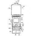
図1は、本発明において工程(Ib)での乾式研磨処理を行うことのできる鋳物砂再生装置の側部概略図であり、21は筐体の本体である。本体1は角型で上下の2段構造に作られ、下部の攪拌槽22と上部の分級槽23の2部分で構成されている。24は攪拌槽22の底部に形成された送風室、25は送風口、26は流動床である。流動床26には、側面に複数の通気口を形成した多数の凸形突起が設けられている。27と28は攪拌槽22の対向側壁に設けられた投入管と送出管、29は透視窓である。投入管27と送出管28は共に攪拌槽22の側壁に斜めに取付けられ、詳しくは示されていないが手動操作により側壁と同一面に設けられた投入口と排出口の開度が調節可能に開閉するようになっている。210は駆動軸、211は左右の軸受け、212はローターである。軸受け211は攪拌槽22の両側壁に取付けられて、駆動軸210を途中の高さで水平方向に保持する。216は規制板、217は排気口、220は工程(Ia)で研磨処理された後に添加剤(A)が添加された回収砂である。
FIG. 1 is a schematic side view of a foundry sand recycling apparatus capable of performing a dry polishing process in the step (Ib) in the present invention, and 21 is a main body of a casing. The main body 1 is a square shape and is made of a two-stage structure of upper and lower parts, and is composed of two parts, a
図1の装置では、投入管27より工程(Ia)での研磨後、添加剤(A)が添加された砂が投入される。攪拌層22内はブロアからの送風が送風口25から流動床26を通して吹き込まれ、砂を流動化させる。流動化された砂は、攪拌槽22内に配置され回転面に傾斜する粗面が形成されて駆動源によって駆動されているローター212及び遠心力により堆積した本揺動板の近傍の砂により研磨されることで、砂の付着物を剥離する。剥離した付着物(剥離有機分等)は攪拌槽22の上部に規制板216を介して連通し集塵口を設けた分級槽23において、砂と分離される。所定時間、処理された後、送出管28(排出口)より再生された鋳物砂が排出される。
In the apparatus of FIG. 1, the sand to which the additive (A) has been added is fed from the charging
本発明では、回収砂100重量部に対して、0.5〜20重量部の水を添加して研磨処理(以下、水添研磨処理)を行うことが好ましい。この水添研磨処理と従来公知の湿式再生法との違いは、湿式再生法では、回収砂の粒子層空隙に水が満たされている状態、即ちスラリー状態にて砂を再生するが、水添研磨処理では、水が粒子間空隙に存在はするものの、完全な連続層としては存在せず、いわゆるファニキュラー域からキャピラリー域における状態で、研磨処理を行う点にある。ここで、水の量は、回収砂100重量部に対して0.5重量部以上であれば回収砂の残留有機分を効率よく除去するのが容易となる。また、水の量は、回収砂100重量部に対して20重量部以下であれば汚水処理装置や過度の乾燥を不要にするのが容易となる。この方法は、少量の水分を使用するものであるため、湿式再生法のような多大な乾燥設備や汚水処理装置を必要とせず、スラリー状態で研磨処理を行う場合に比べ、砂に強い負荷を与えることが出来る。また、機械的に砂表面を処理する方法に比べ、効率よく残留有機分を除去した鋳物砂を、簡易に得ることができる。回収砂の研磨処理時に少量の水を添加することで、強固に接着した残留樹脂分が剥がれ易くなり、更に添加剤(A)の存在下で研磨処理を行う工程(I)により、一旦剥れた残留有機分を砂表面に再付着するのを防止できる結果、回収砂の残留有機分を効率よく除去できるものと考えられる。 In the present invention, it is preferable to add 0.5 to 20 parts by weight of water to 100 parts by weight of recovered sand and perform polishing (hereinafter, hydrogenated polishing). The difference between this hydrogenated polishing treatment and the conventionally known wet regeneration method is that the wet regeneration method regenerates the sand in a state where the voids of the recovered sand are filled with water, that is, in a slurry state. In the polishing process, although water exists in the interparticle voids, it does not exist as a complete continuous layer, and the polishing process is performed in a state from a so-called funicular region to a capillary region. Here, if the amount of water is 0.5 parts by weight or more with respect to 100 parts by weight of the collected sand, it becomes easy to efficiently remove the residual organic content of the collected sand. Moreover, if the amount of water is 20 parts by weight or less with respect to 100 parts by weight of the collected sand, it becomes easy to eliminate the need for sewage treatment equipment and excessive drying. Since this method uses a small amount of moisture, it does not require a large amount of drying equipment and sewage treatment equipment as in the wet regeneration method, and it imposes a stronger load on sand than when polishing in a slurry state. Can be given. Moreover, compared with the method of mechanically treating the sand surface, foundry sand from which residual organic components have been efficiently removed can be easily obtained. By adding a small amount of water during the polishing process of the collected sand, it becomes easy to peel off the strongly adhered residual resin, and further, it is once peeled off by the step (I) of performing the polishing process in the presence of the additive (A). As a result, it is considered that the residual organic content of the recovered sand can be efficiently removed.
本発明では、水添研磨処理(所定量の水の存在下での研磨処理)は、再生鋳物砂の製造工程の何れで行っても良い。また、回収砂の研磨処理が複数行われる場合、その少なくとも1つで水添研磨処理を行うことができる。つまり、本発明の製造方法では、所定量の水の存在下で回収砂の研磨処理を行うことができる。例えば、水添研磨処理を工程(I)と同時に、すなわち、添加剤(A)の存在下での研磨処理の際に水を添加して行うこともできる。また、水添研磨処理を工程(I)とは別に、すなわち、添加剤(A)の存在下での研磨処理とは別に、水添研磨処理工程を設けることができ、前記のように工程(Ia)、(Ib)を有する場合は、それらの何れで水添研磨処理を行っても良い。好ましくは、工程(Ia)で水を添加して研磨処理した後、工程(Ib)の添加剤(A)の存在下の研磨処理(実質的に水の不存在下であることが好ましい)を行うことである。水添研磨処理を行う工程が、工程(I)とは別に設けられる場合や、工程(Ia)で行われる場合、実質的に添加剤(A)の不存在下での研磨処理であることが好ましい。 In the present invention, the hydrogenated polishing treatment (polishing treatment in the presence of a predetermined amount of water) may be performed in any of the steps for producing reclaimed foundry sand. Further, when a plurality of polishing processes are performed on the collected sand, at least one of the polishing processes can be performed with hydrogenation. That is, in the production method of the present invention, the recovered sand can be polished in the presence of a predetermined amount of water. For example, the hydrogenated polishing treatment can be performed simultaneously with the step (I), that is, by adding water during the polishing treatment in the presence of the additive (A). In addition, the hydrogenated polishing treatment can be provided separately from the step (I), that is, separately from the polishing treatment in the presence of the additive (A). In the case of having Ia) and (Ib), hydrogenated polishing treatment may be performed with any of them. Preferably, after polishing by adding water in step (Ia), polishing treatment in the presence of additive (A) in step (Ib) (preferably substantially in the absence of water) is preferably performed. Is to do. When the step of performing the hydrogenated polishing process is provided separately from the step (I), or when performed in the step (Ia), it may be a polishing process substantially in the absence of the additive (A). preferable.
本発明では、水添研磨処理を行う工程と、添加剤(A)の存在下での乾式研磨処理(実質的に水の不存在下での研磨処理)を行う工程(I)とを有することができる。すなわち、回収砂100重量部に対して、0.5〜20重量部の水を添加して研磨処理を行った後、添加剤(A)の存在下で乾式研磨処理を行うことができる。なお、前記のように工程(I)において工程(Ia)と工程(Ib)を設ける場合、工程(Ia)において、回収砂100重量部に対して、0.5〜20重量部の水を添加して研磨処理を行うことで、工程(I)とすることができる。従って、以下に説明する水添研磨処理の方法、装置は工程(Ia)の実施に適合したものであることが好ましい。なお、工程(Ia)の一部を水添研磨処理として行うことができ、その場合の順序は問わない。 The present invention includes a step of performing a hydrogenated polishing process and a step (I) of performing a dry polishing process (polishing process substantially in the absence of water) in the presence of the additive (A). Can do. That is, after adding 0.5 to 20 parts by weight of water to 100 parts by weight of recovered sand and performing a polishing process, a dry polishing process can be performed in the presence of the additive (A). When the steps (Ia) and (Ib) are provided in the step (I) as described above, 0.5 to 20 parts by weight of water is added to 100 parts by weight of the recovered sand in the step (Ia). And it can be set as process (I) by performing a grinding | polishing process. Therefore, it is preferable that the method and apparatus for the hydrogenated polishing treatment described below are suitable for the implementation of the step (Ia). In addition, a part of process (Ia) can be performed as a hydrogenation polishing process, and the order in that case is not ask | required.
水添研磨処理を行う工程は、回収砂に予め水分を添加したものを、前記研磨処理装置に投入して行ってもよいし、回収砂を前記研磨処理装置に投入すると同時に、スプレー等によって水を散布して行ってもよい。本発明の水添研磨処理は、水が添加された砂の流動化を容易に行う観点から、垂直軸回転型、水平軸回転型、振動型の各装置を用いた研磨方法で行うのが好ましく、垂直軸回転型の装置を用いた研磨方法がより好ましい。 The step of performing the hydro-polishing treatment may be performed by adding the water previously added to the collected sand to the polishing apparatus, or at the same time as adding the collected sand to the polishing apparatus, You may carry out by spraying. The hydrogenated polishing treatment of the present invention is preferably performed by a polishing method using vertical axis rotation type, horizontal axis rotation type, and vibration type apparatuses from the viewpoint of easily fluidizing sand to which water has been added. A polishing method using a vertical axis rotation type apparatus is more preferable.
具体的には、水を添加した回収砂を上部が開口した高速回転ドラムに落下供給し、あるいは、回収砂を上部が開口した高速回転ドラムに落下供給し水を添加し、回転ドラムの回転による粒子相互間の摩擦、衝突、押しつけによって研磨加工を行うとともに遠心力で飛散する水を添加した回収砂をその上部周縁に配置した環状体に滞留させて同様の磨砕加工を行い、さらに前記回転ドラムと環状体とが形成するスペースでこれらの水を添加した回収砂を流動させ、このような流動磨砕加工によって回収砂を再生することができる。これは、後述の図2の装置を用いて行うことが好適である。 Specifically, the recovered sand to which water has been added is dropped and supplied to a high-speed rotating drum having an upper opening, or the collected sand is dropped and supplied to a high-speed rotating drum having an upper opening, and water is added to the recovered sand. Abrasion processing is performed by friction, collision, and pressing between particles, and recovered sand to which water scattered by centrifugal force is added is retained in an annular body arranged at the upper peripheral edge, and the same grinding process is performed, and further, the rotation The recovered sand to which these waters are added is fluidized in the space formed by the drum and the annular body, and the recovered sand can be regenerated by such fluid grinding. This is preferably performed using the apparatus shown in FIG.
高速回転ドラムの回転数としては、より効果的な摩擦処理を与える観点から1分間当り1000回転以上、3000回転以下が好ましく、2000〜2800回転がより好ましい。高速で、ドラムを回転させることにより、短時間で高効率な再生処理が可能で、また設備もコンパクトにすることが出来る。 The number of rotations of the high-speed rotating drum is preferably 1000 or more and 3000 or less, more preferably 2000 to 2800, per minute from the viewpoint of providing a more effective friction treatment. By rotating the drum at high speed, highly efficient regeneration processing can be performed in a short time, and the equipment can be made compact.
水添研磨処理を行う工程における、水の量は、回収砂の残留有機分を効率よく除去し、かつ、汚水処理装置や過度の乾燥を不要にする観点から、回収砂100重量部に対して、0.5〜20重量部であり、0.5〜10重量部が好ましく、1〜5重量部がより好ましい。 The amount of water in the process of performing the hydro-polishing process is based on 100 parts by weight of the collected sand from the viewpoint of efficiently removing the residual organic content of the collected sand and eliminating the need for sewage treatment equipment and excessive drying. 0.5 to 20 parts by weight, preferably 0.5 to 10 parts by weight, and more preferably 1 to 5 parts by weight.
本発明で、添加剤(A)の存在下での研磨処理を行う工程(I)は、例えば、前述のような研磨処理を施すことによって行われる。本発明では、工程(I)は、実質的に水の不存在下で行うことが好ましい。ここで、実質的に水の不存在下とは、乾式研磨処理を行う砂中の水分量は、乾式研磨処理にて残留樹脂分と効率よく除去する観点から、0.2重量%以下が好ましく、0.1重量%以下がより好ましい。従って、水添研磨処理工程を設ける場合は、この範囲まで水分量を低減した砂により工程(I)を行うことが好ましい。 In the present invention, the step (I) for carrying out the polishing treatment in the presence of the additive (A) is performed, for example, by performing the polishing treatment as described above. In the present invention, the step (I) is preferably performed in the substantial absence of water. Here, substantially in the absence of water means that the amount of water in the sand subjected to the dry polishing treatment is preferably 0.2% by weight or less from the viewpoint of efficiently removing the residual resin content in the dry polishing treatment. 0.1% by weight or less is more preferable. Therefore, when providing a hydrogenated polishing process, it is preferable to perform process (I) with the sand which reduced the moisture content to this range.
ここで、砂中の水分量は、JACT試験法S−9の砂の水分量測定法により求めることが出来る。 Here, the moisture content in the sand can be determined by the sand moisture content measurement method of JACT test method S-9.
水添研磨処理された回収砂を添加剤(A)の存在下で乾式研磨処理する工程は、水添研磨処理された回収砂を、流動攪拌等を施しながら乾燥と同時に研磨処理を行う方法も可能であるが、回収砂の残留有機分を効率よく除去する観点から、水添研磨処理された回収砂を乾燥する工程の後に、乾燥処理された回収砂に研磨処理する工程を施すことが好ましい。乾燥処理された回収砂を研磨処理する場合、水添研磨処理後、湿態状態にある回収砂に添加剤(A)を添加して乾燥して乾式研磨処理に供する、あるいは水添研磨処理後、回収砂を乾燥した後、添加剤(A)を添加して乾式研磨処理に供することができる。 The process of dry-polishing the recovered sand that has been subjected to hydrogenated polishing in the presence of the additive (A) is a method in which the recovered sand that has been subjected to hydrogenated polishing is subjected to polishing simultaneously with drying while subjecting it to fluid agitation and the like. Although it is possible, from the viewpoint of efficiently removing the residual organic content of the recovered sand, it is preferable to subject the dried recovered sand to a polishing treatment after the step of drying the hydrogenated polished recovered sand. . In the case of polishing the recovered sand that has been dried, after the hydrogenated polishing process, the additive (A) is added to the recovered sand in a wet state and dried for use in a dry polishing process, or after the hydrogenated polishing process. After the recovered sand is dried, the additive (A) can be added and subjected to a dry polishing treatment.
水添研磨処理された回収砂を乾燥する工程は、例えば、水添研磨処理された回収砂をロータリーキルンや、流動層など公知の乾燥装置で乾燥する方法や乾燥し易い場所に放置することによって自然乾燥させる方法をとることができる。また、乾燥を促進する為に補助的に熱風等を付与することによって乾燥させる方法が挙げられる。 The process of drying the recovered sand that has been subjected to the hydrogenated polishing treatment is natural, for example, by leaving the recovered sand that has been subjected to the hydrogenated polishing treatment in a method of drying with a known drying apparatus such as a rotary kiln or a fluidized bed, or by leaving it in a place where it can be easily dried. The method of drying can be taken. Moreover, in order to accelerate | stimulate drying, the method of drying by providing hot air etc. supplementarily is mentioned.
以下、水添研磨処理を行う工程、次いで乾式処理による工程(I)を行う本発明の再生鋳物砂の製造方法について実施の形態を図面に基づき説明する。 Hereinafter, an embodiment of a method for producing reclaimed foundry sand according to the present invention in which a step of performing a hydrogenated polishing treatment and then a step (I) by dry treatment are performed will be described with reference to the drawings.
図2は、本発明の水添研磨処理を行うのに適した装置の一例であり、垂直軸回転型の研磨処理装置である。図2の装置は、回収砂を受容する開口を備えた回転ドラムと、該回転ドラムの上部周縁に近接して配置され、かつ、この回転ドラムから遠心力によって飛散する回収砂を受容する環状体と、前記回転ドラムに受容された回収砂に水を添加する手段と、を備え、前記回転ドラムの回転によって、前記回転ドラムと環状体とが形成するスペースで粒子相互間の摩擦、衝突、押しつけによる回収砂の研磨処理を行う、垂直軸回転型研磨装置である。図1において、1は回収砂投入のための開口、2は回収砂を受容する開口を備えた高速回転ドラム、3は環状体、4は水添研磨処理された回収砂、5は再生砂排出口、Aは投入された回収砂に水を添加する手段であり、例えば、ノズル等が挙げられる。図2の装置による処理の概要は次の通りである。鋳造後の鋳型をクラッシャーで処理した回収砂は、上部開口1より投入される。投入された回収砂に、Aより水が一定量添加される。粒子間空隙が完全に満たされない程度の適量の水を加えられた砂は、スラリー状態になることなく、湿態砂の状態で高速回転ドラム2の上部と環状体3の間に滞留し、高速に回転する高速回転ドラム2による遠心力で、水分を加えられた砂は環状体3に押し付けられつつ、砂同士の研磨及び3との研磨が行われる。該装置はその構造として、水分が所定量添加された砂が滞留しかつ間隙より適当な滞留時間を持ちつつ排出されるように、当て板等が設計されている。再生砂排出口5より処理を終えた砂は外部に排出され、引き続き乾燥及び乾式研磨処理に供される。その際、湿態砂の形で排出されるため、従来の湿式再生と異なり、排水は発生せず、また、本工程においては、粉塵の発生も少ない。
FIG. 2 shows an example of an apparatus suitable for performing the hydrogenated polishing process of the present invention, which is a vertical axis rotating type polishing apparatus. The apparatus shown in FIG. 2 includes a rotating drum having an opening for receiving the collected sand, and an annular body that is disposed in the vicinity of the upper peripheral edge of the rotating drum and that receives the collected sand scattered from the rotating drum by centrifugal force. And means for adding water to the collected sand received in the rotating drum, and friction, collision and pressing between particles in a space formed by the rotating drum and the annular body by rotation of the rotating drum This is a vertical axis rotating type polishing apparatus that performs polishing processing of the recovered sand. In FIG. 1, 1 is an opening for charging collected sand, 2 is a high-speed rotating drum having an opening for receiving the collected sand, 3 is an annular body, 4 is recovered sand that has been subjected to hydro-polishing, and 5 is waste sand for recycling. The outlet, A, is a means for adding water to the collected recovered sand, and examples thereof include a nozzle. The outline of processing by the apparatus of FIG. 2 is as follows. The recovered sand obtained by treating the cast mold with a crusher is introduced from the upper opening 1. A fixed amount of water is added from A to the collected collected sand. Sand to which an appropriate amount of water is added so that the interparticle voids are not completely filled does not become a slurry, but stays between the upper part of the high-speed
水添研磨処理では、一般にある程度の長さの処理時間があった方が、再生処理効果が高くなる。例えば、図2の装置では、回収砂4が回転ドラム2と環状体3のスペースに滞留して研磨処理を受ける時間、すなわち滞留時間と、排出されるまでの時間とのバランスをとることが良好な再生効果を得る観点から好ましい。図2の装置では、滞留時間は、回転ドラムの上部周縁と環状体とが形成する隙間の長さ、環状体の深さ、回収砂の投入速度などにより調整できる。この観点から、垂直軸回転型研磨装置の回転ドラム2の上部周縁と環状体3とが、回収砂4の平均粒子径の5〜50倍、更に10〜25倍の長さの隙間6を形成する(図3)ことが好ましく、具体的に隙間の長さは1〜15mm、更に1.5〜6mm、特に1.5〜4mmが好ましい。一般に、回収砂の平均粒子径は75〜600μm程度である。この回収砂の平均粒子径は、JISの鋳物砂の粒度分布試験方法(Z 2601)に従って測定した回収砂の粒度分布の結果をもとに、JISの粒子径測定の結果の表現(Z 8819−1)に記載の方法により、質量基準積算分率が0.5となる粒子径(メジアン径)として得られる。また、回収砂の投入速度は、1〜10t/hr、更に1.5〜5t/hrが好ましい。これらの条件を採用する場合、回転ドラムの回転数は前記した範囲が好ましい。
In the hydrogenated polishing treatment, generally, the regeneration treatment effect becomes higher when the treatment time has a certain length. For example, in the apparatus shown in FIG. 2, it is preferable to balance the time during which the recovered sand 4 stays in the space between the
また、水添研磨処理での研磨処理効率を高めるために、回収砂や水の投入位置を調整することが好ましい。垂直軸回転型研磨装置では、水、更には水と回収砂とを、垂直軸回転型研磨装置の回転ドラム2の中央、すなわち回転軸の近傍に投入することが好ましい。尚、回転軸の近傍とは、回転ドラムの大きさにもよるので一概には言えないが、回転軸から(回転ドラムの直径/4)の範囲内が好ましく、回転軸から(回転ドラムの直径/5)の範囲内がより好ましい。
In addition, in order to increase the polishing efficiency in the hydrogenated polishing process, it is preferable to adjust the input position of the collected sand and water. In the vertical axis rotating type polishing apparatus, it is preferable to introduce water, and further water and recovered sand into the center of the
ここで説明した方法は、工程(Ia)を水添研磨処理により行い、続いて添加剤(A)の存在下に工程(Ib)を行う方法として捉えることができ、水添研磨処理を経た回収砂は、前述の工程(Ib)の方法で研磨処理して再生鋳物砂とすることができる。 The method described here can be regarded as a method in which the step (Ia) is performed by hydrogenated polishing, and then the step (Ib) is performed in the presence of the additive (A). The sand can be polished by the method of the above-mentioned step (Ib) to obtain recycled casting sand.
本発明の製造方法により得られた再生鋳物砂は、鋳型の製造に用いられる。鋳型の製造方法としては、本発明の製造方法により得られた再生鋳物砂を用いる鋳型の製造方法であれば特に限定されないが、具体的には、当該再生砂を、有機系バインダーで硬化させる工程を有する、鋳型の製造方法である。有機系バインダーとしては、アルカリフェノール樹脂、フラン樹脂、熱硬化性フェノール樹脂(シェルモールド)、ウレタン樹脂等が挙げられ、有機バインダーを用いて、それぞれ従来公知の硬化方法により鋳型を製造することができる。これらバインダーは、当該再生砂100重量部に対して、通常0.05〜10重量部添加するのが好適である。また、従来公知のシランカップリング剤、添加剤等を用いても構わない。本発明の鋳型の製造方法は、粘結剤としてアルカリフェノール樹脂を使用して、該粘結剤を有機エステル化合物で硬化させて得られた鋳型に適用されることが好ましい。 The recycled foundry sand obtained by the production method of the present invention is used for producing a mold. The mold production method is not particularly limited as long as it is a mold production method using the reclaimed foundry sand obtained by the production method of the present invention. Specifically, the step of curing the reclaimed sand with an organic binder. It is a manufacturing method of the casting_mold | template which has these. Examples of the organic binder include alkali phenol resin, furan resin, thermosetting phenol resin (shell mold), urethane resin, and the like, and a mold can be produced by a conventionally known curing method using an organic binder. . It is preferable to add 0.05 to 10 parts by weight of these binders with respect to 100 parts by weight of the recycled sand. Moreover, you may use a conventionally well-known silane coupling agent, an additive, etc. The mold production method of the present invention is preferably applied to a mold obtained by using an alkali phenol resin as a binder and curing the binder with an organic ester compound.
実施例1
球形度0.99、Al2O3/SiO2比(重量比)=1.9、SiO2及びAl2O3の合計量が94重量%(その他は、TiO2:2.9重量%、Fe2O3:1.3重量%、及び微量のCaO、MgO、Na2O、K2Oを含む。)の球状人工セラミック鋳物砂100重量部に対して、アルカリフェノール樹脂用硬化剤(カオーステップKC−130、花王クエーカー(株)製)0.30重量部、及びアルカリフェノール樹脂(カオーステップS−660、花王クエーカー(株)製)1.2重量部を加え攪拌し、サンド/メタル比が4の鋳型を造型した。本鋳型に1400℃にて鋳鉄溶湯(FC200)を注湯し、冷却後、鋳型をクラッシャーで処理し回収砂を得た。本回収砂の平均粒子径は200μmであった。この回収砂の100重量部に対してジメチルシリコーンオイル(KF−96−10CS、信越化学工業(株)製)0.1重量部を添加混合した後、一般的な垂直軸回転型の研磨処理装置(ロータリーリクレーマM型、日本鋳造(株)製)にて、回転ドラムの回転数2450rpm、砂投入速度3.1t/hr、A再生(砂層間摩擦再生方式)にて乾式研磨処理を4回繰返し、再生砂を得た(ジメチルシリコーンオイルの添加は最初の研磨処理の際の1回のみ)。回収砂及び再生砂の分析値及び鋳型強度試験結果を表1に示す。尚、LOI及びLOI除去率、並びに鋳型強度は下記する方法にて評価した。
Example 1
Sphericality 0.99, Al 2 O 3 / SiO 2 ratio (weight ratio) = 1.9, the total amount of SiO 2 and Al 2 O 3 is 94% by weight (others are TiO 2 : 2.9% by weight, Fe 2 O 3 : 1.3) % By weight, and 100 parts by weight of spherical artificial ceramic foundry sand containing CaO, MgO, Na 2 O, and K 2 O.) Curing agent for alkaline phenol resin (Kaoh Step KC-130, Kao Quaker ( 0.30 parts by weight) and 1.2 parts by weight of alkali phenol resin (Kaoh Step S-660, manufactured by Kao Quaker) were added and stirred to form a mold having a sand / metal ratio of 4. A cast iron melt (FC200) was poured into the mold at 1400 ° C., and after cooling, the mold was treated with a crusher to obtain recovered sand. The average particle size of the recovered sand was 200 μm. After adding 0.1 parts by weight of dimethyl silicone oil (KF-96-10CS, manufactured by Shin-Etsu Chemical Co., Ltd.) to 100 parts by weight of the recovered sand, a general vertical axis rotating polishing apparatus (Rotary reclaimer M type, manufactured by Nippon Casting Co., Ltd.), dry drum treatment 4 times with a rotating drum rotation speed of 2450 rpm, sand throwing speed 3.1 t / hr, A regeneration (sand sand friction regeneration method) Repeatedly, reclaimed sand was obtained (dimethylsilicone oil was added only once during the first polishing process). Table 1 shows the analysis values of the collected sand and reclaimed sand and the results of the mold strength test. The LOI and the LOI removal rate and the mold strength were evaluated by the following methods.
(1)LOI及びLOI除去率
JACT試験法S−2に基づき鋳物砂中の強熱減量(LOI)を測定し、以下の式によりLOI除去率を算出した。LOIは鋳物砂中の有機物量(残留樹脂量)を示す。
LOI除去率(%)=(1−再生砂のLOI(重量%)/回収砂のLOI(重量%))×100
(1) LOI and LOI removal rate The loss on ignition (LOI) in foundry sand was measured based on JACT test method S-2, and the LOI removal rate was calculated by the following equation. LOI indicates the amount of organic matter (residual resin amount) in the foundry sand.
LOI removal rate (%) = (1-LOI of recycled sand (wt%) / LOI of recovered sand (wt%)) x 100
(2)鋳型強度評価
得られた再生鋳物砂又は回収砂100重量部に対して、アルカリフェノール樹脂(カオーステップS−660、花王クエーカー(株)製)1.0重量部、アルカリフェノール樹脂用硬化剤(カオーステップKC−140、花王クエーカー(株)製)0.25重量部を添加して得られた鋳型について、25℃、55%RHの条件下にてJACT試験法HM−1に基づき、混練1日後の圧縮強度を島津製強度試験機AD−5000で測定した。
(2) Mold strength evaluation With respect to 100 parts by weight of the reclaimed foundry sand or recovered sand, 1.0 part by weight of an alkali phenol resin (Kao Step S-660, manufactured by Kao Quaker Co., Ltd.), curing for an alkali phenol resin Based on JACT test method HM-1 under the conditions of 25 ° C. and 55% RH for a template obtained by adding 0.25 parts by weight of an agent (Kao Step KC-140, manufactured by Kao Quaker Co., Ltd.) The compressive strength one day after kneading was measured with a Shimadzu strength tester AD-5000.
比較例1
ジメチルシリコーンオイルを添加しなかったこと以外は、実施例1と同様に行い再生砂を得た。再生砂の分析値(LOI及びLOI除去率)及び鋳型強度は実施例1と同様に測定した。結果を表1に示す。
Comparative Example 1
Regenerated sand was obtained in the same manner as in Example 1 except that dimethyl silicone oil was not added. The analysis value (LOI and LOI removal rate) and mold strength of the recycled sand were measured in the same manner as in Example 1. The results are shown in Table 1.
実施例2
比較例1で得られた再生砂100重量部に対してジメチルシリコーンオイル(KF−96−10CS、信越化学工業(株)製)0.02重量部を添加混合した後、図1のような流動床を具備した乾式鋳物砂再生装置(ハイブリッドサンドマスター 形式HSM1115、日本鋳造(株)製)で、ローター回転数2600rpmで30分間、砂投入量80kgのバッチ処理にて乾式研磨処理を行い、再生砂を得た。乾式研磨処理を行う際、流動層から剥離有機分を浮遊させて集塵処理を行った。再生砂の分析値(LOI及びLOI除去率)及び鋳型強度は実施例1と同様に測定した。結果を表1に示す。
Example 2
After adding and mixing 0.02 part by weight of dimethyl silicone oil (KF-96-10CS, manufactured by Shin-Etsu Chemical Co., Ltd.) to 100 parts by weight of the reclaimed sand obtained in Comparative Example 1, the flow shown in FIG. Dry sand sand recycling equipment (hybrid sand master type HSM1115, manufactured by Nippon Casting Co., Ltd.) equipped with a floor is used for 30 minutes at a rotor speed of 2600 rpm, and dry sanding is performed in a batch process with a sand input of 80 kg. Got. When performing the dry polishing treatment, the organic particles separated from the fluidized bed were suspended to perform dust collection treatment. The analysis value (LOI and LOI removal rate) and mold strength of the recycled sand were measured in the same manner as in Example 1. The results are shown in Table 1.
比較例2
ジメチルシリコーンオイルを添加しなかったこと以外は実施例2と同様に行い再生砂を得た。再生砂の分析値(LOI及びLOI除去率)及び鋳型強度は実施例1と同様に測定した。結果を表1に示す。
Comparative Example 2
Regenerated sand was obtained in the same manner as in Example 2 except that dimethyl silicone oil was not added. The analysis value (LOI and LOI removal rate) and mold strength of the recycled sand were measured in the same manner as in Example 1. The results are shown in Table 1.
実施例3
実施例1で用いた回収砂を図2に示す構造の水を添加して研磨処理できる研磨処理装置にて、回収砂(回収砂中の水分量は0.16重量%)100重量部に対して水を4重量部になるように、砂投入速度2.7t/hrにて高速回転ドラム2に投入し回転数2542rpmにて研磨処理を行った。回収砂は高速回転ドラム2の中央に投入し、対応する水は高速回転ドラム2の中央に投入した。この研磨処理装置の高速回転ドラム2の上部周縁と環状体3の隙間6は5mm、環状体3の深さは100mmのもの(図3参照)を使用し、研磨処理時の砂滞留時間は26秒であった。
Example 3
With respect to 100 parts by weight of the collected sand (the water content in the collected sand is 0.16% by weight) in a polishing apparatus that can polish the recovered sand used in Example 1 by adding water having the structure shown in FIG. Then, the sand was fed into the high-speed
得られた湿態砂にジメチルシリコーンオイル(KF−96−10CS、信越化学工業(株)製)を湿態砂100重量部に対して0.04重量部添加した後、コンクリートミキサーにて撹拌しながら150℃の熱風を吹き込むことにより乾燥した。乾燥後の回収砂中の水分量は0.06重量%であった。 After adding 0.04 part by weight of dimethyl silicone oil (KF-96-10CS, manufactured by Shin-Etsu Chemical Co., Ltd.) to 100 parts by weight of wet sand, the resulting wet sand is stirred with a concrete mixer. However, it was dried by blowing hot air at 150 ° C. The water content in the recovered sand after drying was 0.06% by weight.
得られた乾燥砂を、図1のような流動層を具備した乾式鋳物砂再生装置(日本鋳造製ハイブリッドサンドマスター 形式HSM1115)を用い、ローター回転数2600rpmにて12分間、砂投入量80kgのバッチ処理にて乾式研磨処理を行い、再生砂を得た。乾式研磨処理を行う際、流動層から剥離有機分を浮遊させて集塵処理を行った。再生砂の分析値(LOI及びLOI除去率)と鋳型強度を実施例1と同様に測定し、表1に示した。 The obtained dry sand is batched with a sand casting amount of 80 kg for 12 minutes at a rotor rotational speed of 2600 rpm using a dry casting sand regenerator equipped with a fluidized bed as shown in FIG. 1 (hybrid sand master type HSM1115 manufactured by Nippon Casting). A dry polishing process was performed to obtain recycled sand. When performing the dry polishing treatment, the organic particles separated from the fluidized bed were suspended to perform dust collection treatment. Analytical values (LOI and LOI removal rate) and mold strength of the recycled sand were measured in the same manner as in Example 1, and are shown in Table 1.
実施例1より3で使用したジメチルシリコーンオイル(KF−96−10CS、信越化学工業(株)製)は25℃での表面張力が20mN/mであり、25℃での粘度が10mm2/sであり、1気圧での沸点が229℃以上(メーカー発表のカタログ値より)である。なお、表面張力の測定は、クルス社(Kruess GmbH)製の自動表面張力計(プロセッサーテンションメーター K100)を用いて行った(以下同様)。 The dimethyl silicone oil (KF-96-10CS, manufactured by Shin-Etsu Chemical Co., Ltd.) used in Examples 1 to 3 has a surface tension at 25 ° C. of 20 mN / m and a viscosity at 25 ° C. of 10 mm 2 / s. The boiling point at 1 atm is 229 ° C. or higher (from the catalog value announced by the manufacturer). The surface tension was measured using an automatic surface tension meter (processor tension meter K100) manufactured by Kruess GmbH (the same applies hereinafter).
上記実施例1〜3及び比較例1〜2における処理手順を図4のフローに示した。 The processing procedure in Examples 1 to 3 and Comparative Examples 1 and 2 is shown in the flow of FIG.

表1の結果から、実施例ではシリコーンオイルを添加することにより、比較例に比べて、効率よく残留有機分を除去でき、それを用いた鋳型は顕著な強度を発現できていることがわかる。更に鋳物砂は繰り返し使用されるため、本発明の再生鋳物砂の製造方法を繰り返し用いれば、飽和する再生砂のLOIを大幅に下げることができる。このことは単にLOI低減による鋳型からのガス発生量低減だけでなく、鋳型強度の向上により樹脂添加量を低減できるため大幅にガス欠陥を低減することにつながり当業界で有益である。また、従来の再生技術に対して、再生処理の繰り返し回数を少なくすることができるため、大幅に電力を低減でき、設備コストも大幅に低減できる。 From the results in Table 1, it can be seen that by adding silicone oil in the examples, the residual organic components can be removed more efficiently than in the comparative example, and the mold using the same can express remarkable strength. Further, since the foundry sand is repeatedly used, the LOI of the regenerated sand that is saturated can be greatly reduced by repeatedly using the method for producing the reclaimed foundry sand of the present invention. This not only reduces the amount of gas generated from the mold by reducing the LOI, but also reduces the amount of resin added by improving the mold strength, which leads to a significant reduction in gas defects and is beneficial in the industry. In addition, since the number of repetitions of the regeneration process can be reduced as compared with the conventional regeneration technique, the power can be greatly reduced and the equipment cost can be greatly reduced.
更に、実施例1と比較例2では、残留有機分が実施例1の方が多いにもかかわらず、実施例1の方が比較例2に比べて、鋳型強度が大きく優れている。 Furthermore, in Example 1 and Comparative Example 2, although the residual organic content is larger in Example 1, Example 1 has a higher mold strength than Comparative Example 2 and is excellent.
通常は、残留有機分の低下と共に鋳型強度は向上するが、長時間研磨したり、研磨回数が多くなりすぎると、比較例1と比較例2の対比のように、残留有機分が低下するにもかかわらず、強度低下がおきる現象があった。これは、研磨処理にて一旦剥れた残留有機分が、砂により細かく粉砕され、砂表面に再付着したことによるもので、このような再付着分は比表面積が大きいため、バインダーの硬化に特に悪影響を及ぼすものと考えられる。 Usually, the mold strength is improved as the residual organic content is reduced. However, if the polishing is performed for a long time or the number of times of polishing is excessive, the residual organic content is reduced as in the comparison between Comparative Example 1 and Comparative Example 2. Nevertheless, there was a phenomenon that the strength decreased. This is because the residual organic content once peeled off by the polishing process is finely crushed by the sand and reattached to the sand surface. Since such a reattachment has a large specific surface area, the binder is hardened. This is considered to have an adverse effect.
一方、本発明においては、実施例1と実施例2の比較のように、残留有機分の低下と共に、鋳型強度が向上している。本発明により、鋳型強度がより向上している理由は明らかではないが、シリコーンオイルが存在することで、一旦剥れた残留有機分の再付着を防止し、集塵と共に除去しやすくすると推察され、鋳型強度に特に悪影響を及ぼす再付着分が少なくなるので、鋳型強度の向上が顕著になるものと考えられる。 On the other hand, in the present invention, as compared with Example 1 and Example 2, the mold strength is improved as the residual organic content is reduced. The reason why the mold strength is further improved by the present invention is not clear, but it is presumed that the presence of silicone oil prevents reattachment of residual organic components that have been peeled off and facilitates removal together with dust collection. Since the amount of reattachment that has a particularly bad influence on the mold strength is reduced, it is considered that the improvement of the mold strength becomes remarkable.
実施例3では水添研磨工程後の砂に対してシリコーンオイルを添加することにより、実施例2と比べて短時間の再生処理で効率よく残留有機分を除去でき、その再生砂を用いた鋳型は顕著な強度を発現できていることが分かる。また、設備としても乾式研磨処理を多く繰返す必要がないため、多段式の設備を導入する必要がなく、簡便な設備で再生処理が可能であることが分かる。 In Example 3, by adding silicone oil to the sand after the hydro-polishing process, residual organic components can be efficiently removed in a shorter regeneration process than in Example 2, and a mold using the regenerated sand is used. It can be seen that is able to express remarkable strength. Moreover, since it is not necessary to repeat many dry polishing processes as equipment, it is not necessary to introduce multistage equipment, and it can be seen that regeneration processing can be performed with simple equipment.
実施例4〜9及び比較例3〜5
実施例1に示した球状人工セラミック鋳物砂100重量部に対して、アルカリフェノール樹脂用硬化剤(カオーステップKC−130、花王クエーカー(株)製)0.30重量部、及びアルカリフェノール樹脂(カオーステップS−660、花王クエーカー(株)製)1.2重量部を加え攪拌し、サンド/メタル比が4の鋳型を造型した。本鋳型に1400℃にて鋳鉄溶湯(FC200)を注湯し、冷却後、鋳型をクラッシャーで処理し回収砂を得た。この回収砂を新東工業(株)製 USR型砂再生機を用い、砂投入速度3.0t/hrにて乾式研磨処理を2回繰返し再生砂を得た。この再生砂を用い前記した鋳型の造型、鋳込をもう1回行ない、冷却後、鋳型をクラッシャーで処理し、LOIが0.79%の回収砂を得た。この回収砂を前記したUSR砂再生機を用い前記条件(砂投入量3.0t/hr、2回乾式研磨処理)にて砂再生を行いLOIが0.53%の再生砂を得、この再生砂を評価用の元砂として使用した。この再生砂100重量部に各種添加剤を0.04重量部添加混合した後、乾式鋳物砂再生装置(ハイブリッドサンドマスター 形式HSM1115、日本鋳造(株)製)で、ローター回転数2600rpmで処理時間6分、12分、30分、砂投入量80kgのバッチ処理にて乾式研磨処理を行い、再生砂を得た。乾式研磨処理を行う際、流動層から剥離有機分を浮遊させて集塵処理を行った。各処理時間における再生砂の分析値(LOI)及び鋳型強度を実施例1と同様に測定した。結果を表2に示す。
Examples 4-9 and Comparative Examples 3-5
With respect to 100 parts by weight of the spherical artificial ceramic foundry sand shown in Example 1, 0.30 part by weight of a curing agent for alkaline phenol resin (Kaoh Step KC-130, manufactured by Kao Quaker Co., Ltd.) and alkali phenol resin (Kaoh) Step S-660, manufactured by Kao Quaker Co., Ltd. (1.2 parts by weight) was added and stirred to form a mold having a sand / metal ratio of 4. Cast iron melt (FC200) was poured into this mold at 1400 ° C., and after cooling, the mold was treated with a crusher to obtain recovered sand. Using this recovered sand, a dry sanding process was repeated twice using a USR sand regenerator manufactured by Shinto Kogyo Co., Ltd. at a sand charging rate of 3.0 t / hr to obtain reclaimed sand. Using this reclaimed sand, the mold was cast and cast once again, and after cooling, the mold was treated with a crusher to obtain recovered sand having a LOI of 0.79%. This recovered sand is regenerated using the USR sand regenerator described above under the above conditions (sand input amount 3.0 t / hr, twice dry polishing treatment) to obtain reclaimed sand having a LOI of 0.53%. Sand was used as the original sand for evaluation. After adding 0.04 parts by weight of various additives to 100 parts by weight of this reclaimed sand, a dry casting sand reclaimer (Hybrid Sandmaster Model HSM1115, manufactured by Nippon Casting Co., Ltd.) and a processing time of 6 at a rotor rotational speed of 2600 rpm. Mineral, 12 minutes, 30 minutes, and a dry polishing process was performed in a batch process with a sand input of 80 kg to obtain reclaimed sand. When performing the dry polishing treatment, the organic particles separated from the fluidized bed were suspended to perform dust collection treatment. The analysis value (LOI) and mold strength of the regenerated sand at each treatment time were measured in the same manner as in Example 1. The results are shown in Table 2.
実施例4〜9及び比較例3〜5においては、2回目の鋳込後の処理手順が図4に示した実施例2、比較例2のフローに対応し、回収砂は2回目の鋳込後のものであり、シリコーンオイルに変えて各種添加剤を用いた。 In Examples 4 to 9 and Comparative Examples 3 to 5, the processing procedure after the second casting corresponds to the flow of Example 2 and Comparative Example 2 shown in FIG. Various additives were used instead of silicone oil.
比較例6
シリコーンオイルの添加を2回目の鋳型の造型時に行い、ハイブリッドサンドマスター処理前には添加を行わなかった以外は実施例4と同様にして再生砂を得た。各処理時間における再生砂の分析値(LOI)及び鋳型強度を実施例1と同様に測定した。結果を表2に示す。
Comparative Example 6
Regenerated sand was obtained in the same manner as in Example 4 except that silicone oil was added at the time of molding the mold for the second time and that addition was not performed before the hybrid sand master treatment. The analysis value (LOI) and mold strength of the regenerated sand at each treatment time were measured in the same manner as in Example 1. The results are shown in Table 2.
実施例4〜9及び比較例3〜6において、ジメチルシリコーンオイルは信越化学工業(株)製 KF−96−30CSを使用した。エチルシリケート縮合物にはコルコート(株)製 エチルシリケート40を、ポリオキシエチレンラウリルエーテル(EO平均付加モル数2)には花王(株)製 エマルゲン102KGを使用した。オレイルアルコール、1−オクタノール、1,4−ブタンジオール、1−ブタノールおよびオレイン酸は和光純薬工業(株)製の試薬を使用した。それらの物性は表2に記載する。なお、実施例4、7、及び比較例6で用いた添加剤の沸点はメーカー発表のカタログ値によるものである。 In Examples 4 to 9 and Comparative Examples 3 to 6, KF-96-30CS manufactured by Shin-Etsu Chemical Co., Ltd. was used as the dimethyl silicone oil. Colcon Co., Ltd. ethyl silicate 40 was used for the ethyl silicate condensate, and Kao Co., Ltd. Emulgen 102KG was used for polyoxyethylene lauryl ether (EO average addition mole number 2). For oleyl alcohol, 1-octanol, 1,4-butanediol, 1-butanol and oleic acid, reagents manufactured by Wako Pure Chemical Industries, Ltd. were used. Their physical properties are listed in Table 2. In addition, the boiling point of the additive used in Examples 4 and 7 and Comparative Example 6 is based on the catalog value published by the manufacturer.
各実施例では、短時間の研磨処理(ハイブリッドサンドマスター)にてLOIが低下しており、得られる再生砂を用いた鋳型の強度も向上している。 In each Example, LOI is lowered by a short polishing process (hybrid sand master), and the strength of the mold using the obtained recycled sand is also improved.
添加剤を鋳型造型時に添加したものでは砂再生時のLOI低減効果及び鋳型強度の向上効果が見られなかった。添加剤が鋳込み時の熱などで分解したため効果が得られなかったものと考える。 When the additive was added at the time of mold making, the LOI reduction effect at the time of sand regeneration and the improvement effect of the mold strength were not seen. It is thought that the effect was not obtained because the additive was decomposed by heat during casting.
21 筐体の本体
22 下部の攪拌槽
23 上部の分級槽
24 送風室
25 送風口
26 流動床
220 回収砂
DESCRIPTION OF
Claims (8)
Priority Applications (1)
| Application Number | Priority Date | Filing Date | Title |
|---|---|---|---|
| JP2008231954A JP5297731B2 (en) | 2007-09-12 | 2008-09-10 | Recycled casting sand manufacturing method |
Applications Claiming Priority (5)
| Application Number | Priority Date | Filing Date | Title |
|---|---|---|---|
| JP2007236707 | 2007-09-12 | ||
| JP2007236707 | 2007-09-12 | ||
| JP2008031503 | 2008-02-13 | ||
| JP2008031503 | 2008-02-13 | ||
| JP2008231954A JP5297731B2 (en) | 2007-09-12 | 2008-09-10 | Recycled casting sand manufacturing method |
Publications (2)
| Publication Number | Publication Date |
|---|---|
| JP2009214178A JP2009214178A (en) | 2009-09-24 |
| JP5297731B2 true JP5297731B2 (en) | 2013-09-25 |
Family
ID=40452137
Family Applications (1)
| Application Number | Title | Priority Date | Filing Date |
|---|---|---|---|
| JP2008231954A Active JP5297731B2 (en) | 2007-09-12 | 2008-09-10 | Recycled casting sand manufacturing method |
Country Status (5)
| Country | Link |
|---|---|
| US (1) | US8551373B2 (en) |
| EP (1) | EP2191908B1 (en) |
| JP (1) | JP5297731B2 (en) |
| CN (1) | CN101801561B (en) |
| WO (1) | WO2009035134A1 (en) |
Families Citing this family (26)
| Publication number | Priority date | Publication date | Assignee | Title |
|---|---|---|---|---|
| CN102665961B (en) * | 2009-12-24 | 2015-05-27 | 花王株式会社 | Process for production of molds |
| JP2014050957A (en) * | 2010-06-17 | 2014-03-20 | Tokyo Electron Ltd | Substrate polishing means and substrate polishing device, and substrate polishing system |
| JP5460537B2 (en) | 2010-06-17 | 2014-04-02 | 東京エレクトロン株式会社 | Substrate back surface polishing apparatus, substrate back surface polishing system, substrate back surface polishing method, and recording medium recording substrate back surface polishing program |
| JP5126721B2 (en) * | 2010-09-03 | 2013-01-23 | 太洋マシナリー株式会社 | Cast sand regenerating method, batch centrifugal polishing machine and batch kneader used in the method |
| DE102011081530A1 (en) * | 2011-08-25 | 2013-02-28 | Bayerische Motoren Werke Aktiengesellschaft | Process for the regeneration of the sand from sand molds and cores |
| EP2692460B1 (en) | 2012-07-30 | 2015-02-25 | Hüttenes-Albertus Chemische-Werke GmbH | Particulate refractory compositions for use in the manufacture of foundry moulds and cores, methods of preparing same and corresponding uses |
| BR112014030963B1 (en) * | 2012-08-23 | 2019-04-16 | Sintokogio, Ltd. | SANDWISE RECOVERY APPARATUS |
| CN103664198A (en) * | 2012-08-30 | 2014-03-26 | 刘明宗 | Mullite recycling method and mullite recycling system |
| CN103100645A (en) * | 2012-12-10 | 2013-05-15 | 马鞍山市万鑫铸造有限公司 | Method for preparing casting molding sand by using slag |
| JP6188502B2 (en) * | 2013-09-06 | 2017-08-30 | 大木産業株式会社 | Casting sand recycling process |
| JP6242212B2 (en) * | 2013-12-27 | 2017-12-06 | 花王株式会社 | Method for producing mold composition and method for producing mold |
| CN104588567A (en) * | 2014-12-01 | 2015-05-06 | 繁昌县恒鑫汽车零部件有限公司 | Shock molding back sand and preparation method thereof |
| CN104692782B (en) * | 2015-02-17 | 2016-08-17 | 辽宁航安特铸材料有限公司 | A kind of method utilizing waste-material-preparing ceramic core |
| CN104889336A (en) * | 2015-06-26 | 2015-09-09 | 龙岩盛丰机械制造有限公司 | V-process cast sand core and preparing method thereof |
| CN105081213B (en) * | 2015-09-08 | 2017-03-29 | 台州市陈氏铜业有限公司 | Precoated sand recycles production technology |
| CN106040968A (en) * | 2016-05-26 | 2016-10-26 | 合肥市田源精铸有限公司 | Water glass waste sand regeneration treatment method used for casting |
| CN105903892A (en) * | 2016-05-26 | 2016-08-31 | 合肥市田源精铸有限公司 | Regeneration treatment method of waste sand core of cold core box for casting |
| CN106001402A (en) * | 2016-05-26 | 2016-10-12 | 合肥市田源精铸有限公司 | Regeneration treatment method for phenolic resin self-hardening sand |
| CN106064231A (en) * | 2016-05-26 | 2016-11-02 | 合肥市田源精铸有限公司 | A kind of regeneration treating method of furan resin self curing sand |
| CN106807882A (en) * | 2017-02-06 | 2017-06-09 | 柳州市柳晶科技有限公司 | Inorganic precoated sand antiquated sand regeneration decomposition helps liquid and antiquated sand renovation process |
| CN107414021A (en) * | 2017-08-12 | 2017-12-01 | 合肥市田源精铸有限公司 | A kind of method that cast used sand prepares regenerated foundry sand |
| JP2019063842A (en) * | 2017-10-04 | 2019-04-25 | 花王株式会社 | Aggregate composition for mold |
| EP3620244B1 (en) | 2018-09-07 | 2021-06-30 | HÜTTENES-ALBERTUS Chemische Werke Gesellschaft mit beschränkter Haftung | Method of preparing a particulate refractory composition for use in the manufacture of foundry moulds and cores, corresponding uses, and reclamation mixture for thermal treatment |
| CN110564004B (en) * | 2019-09-17 | 2021-07-06 | 马鞍山市三川机械制造有限公司 | Preparation method for reprocessing rubber and plastic filler by recycling waste resin molding sand |
| EP3797896A1 (en) * | 2019-09-27 | 2021-03-31 | Finn Recycling OY | Cleaning sand used at foundry |
| WO2021152663A1 (en) * | 2020-01-27 | 2021-08-05 | 日本鋳造株式会社 | Sand manufacturing machine, sand grinding machine, and sand screening machine |
Family Cites Families (16)
| Publication number | Priority date | Publication date | Assignee | Title |
|---|---|---|---|---|
| JPS6163333A (en) | 1984-09-05 | 1986-04-01 | Naigai Taika Kogyo Kk | Production of molding material for casting |
| US5190993A (en) * | 1988-04-08 | 1993-03-02 | Borden, Inc. | Process to enhance the tensile strength of reclaimed sand bonded with ester cured alkaline phenolic resin using an aminosilane solution |
| DE4010377A1 (en) * | 1990-03-30 | 1991-10-02 | Vnii Litejnogo Mash | Moulding sand recovery improving quality of sand - using thermal treatment and mechanical action to recycle sand with reduced energy consumption |
| JP2831794B2 (en) * | 1990-04-03 | 1998-12-02 | 花王株式会社 | Method of manufacturing sand mold for castings |
| JPH06154941A (en) | 1992-11-20 | 1994-06-03 | Kurimoto Ltd | Reconditioning method for molding sand and production of casting mold |
| JP3314315B2 (en) | 1993-09-14 | 2002-08-12 | 日本鋳造株式会社 | Casting sand refining classifier |
| US5816312A (en) * | 1994-09-30 | 1998-10-06 | Mazda Motor Corporation | Method of and apparatus for reclaiming foundry sand |
| JPH1059711A (en) | 1996-08-12 | 1998-03-03 | Daicel Amiboshi Sangyo Kk | Magnesium hydroxide and production of aqueous liquid suspension thereof |
| GB9624340D0 (en) | 1996-11-22 | 1997-01-08 | Foseco Int | Sand reclamation |
| JP3878496B2 (en) | 2002-02-28 | 2007-02-07 | 山川産業株式会社 | Mold sand and manufacturing method thereof |
| US7673668B2 (en) | 2002-12-09 | 2010-03-09 | Kao Corporation | Spherical casting sand |
| JP4326916B2 (en) | 2002-12-09 | 2009-09-09 | 花王株式会社 | Spherical casting sand |
| JP4305833B2 (en) | 2003-08-21 | 2009-07-29 | 新東工業株式会社 | A method for reclaiming mold sand using a mechanical regenerator. |
| JP4448945B2 (en) | 2004-01-06 | 2010-04-14 | キンセイマテック株式会社 | Mold sand and its manufacturing method |
| GB0410484D0 (en) | 2004-05-11 | 2004-06-16 | Ashland Uk Ltd | Reclamation of ester-cured phenolic resin bonded foundry sands |
| DE102007008149A1 (en) * | 2007-02-19 | 2008-08-21 | Ashland-Südchemie-Kernfest GmbH | Thermal regeneration of foundry sand |
-
2008
- 2008-09-10 JP JP2008231954A patent/JP5297731B2/en active Active
- 2008-09-11 CN CN2008801067567A patent/CN101801561B/en active Active
- 2008-09-11 EP EP08830795.4A patent/EP2191908B1/en not_active Not-in-force
- 2008-09-11 WO PCT/JP2008/066897 patent/WO2009035134A1/en active Application Filing
- 2008-09-11 US US12/676,804 patent/US8551373B2/en not_active Expired - Fee Related
Also Published As
| Publication number | Publication date |
|---|---|
| CN101801561A (en) | 2010-08-11 |
| CN101801561B (en) | 2013-12-04 |
| EP2191908A4 (en) | 2016-11-16 |
| US20100252951A1 (en) | 2010-10-07 |
| EP2191908B1 (en) | 2017-08-09 |
| US8551373B2 (en) | 2013-10-08 |
| JP2009214178A (en) | 2009-09-24 |
| EP2191908A1 (en) | 2010-06-02 |
| WO2009035134A1 (en) | 2009-03-19 |
Similar Documents
| Publication | Publication Date | Title |
|---|---|---|
| JP5297731B2 (en) | Recycled casting sand manufacturing method | |
| JP5110984B2 (en) | Recycled casting sand manufacturing method | |
| JPH0338014B2 (en) | ||
| US3716947A (en) | Abrasive blast cleaning system | |
| CN103567376A (en) | Reproducing method of molding sand | |
| JP5305805B2 (en) | Recycled casting sand manufacturing method | |
| KR20190039722A (en) | Process for recovering sand and active clay from foundry waste | |
| JP4607698B2 (en) | How to recycle waste green sand | |
| WO2002092259A9 (en) | Process for recovering sand and bentonite clay used in a foundry | |
| JP6188502B2 (en) | Casting sand recycling process | |
| CN114080284B (en) | Foundry sand regeneration method | |
| US3542299A (en) | Foundry sand recovery methods | |
| JP2003136185A (en) | Apparatus and method for reconditioning foundry sand | |
| US4449566A (en) | Foundry sand reclamation | |
| WO2006019047A1 (en) | Method and apparatus for producing regenerated foundry sand | |
| JP2948653B2 (en) | Recycling of used foundry sand | |
| US3829029A (en) | Abrasive blast cleaning system | |
| JP5164013B1 (en) | Foundry sand recycling equipment | |
| JP2001038449A (en) | Casting sand regeneration treatment device and casting sand regeneration method | |
| US3690066A (en) | Abrasive blast cleaning system | |
| JPH0413438A (en) | Method and system for regenerating used sand at foundry | |
| WO2019202376A1 (en) | A method of regenerating foundry sand | |
| US5259434A (en) | Method of regenerating used foundry sands | |
| KR200353464Y1 (en) | Reclamating apparatus of used sand | |
| JP5642526B2 (en) | Recycled casting sand manufacturing method |
Legal Events
| Date | Code | Title | Description |
|---|---|---|---|
| A621 | Written request for application examination |
Free format text: JAPANESE INTERMEDIATE CODE: A621 Effective date: 20110616 |
|
| A977 | Report on retrieval |
Free format text: JAPANESE INTERMEDIATE CODE: A971007 Effective date: 20130215 |
|
| A131 | Notification of reasons for refusal |
Free format text: JAPANESE INTERMEDIATE CODE: A131 Effective date: 20130219 |
|
| A521 | Request for written amendment filed |
Free format text: JAPANESE INTERMEDIATE CODE: A523 Effective date: 20130412 |
|
| TRDD | Decision of grant or rejection written | ||
| A01 | Written decision to grant a patent or to grant a registration (utility model) |
Free format text: JAPANESE INTERMEDIATE CODE: A01 Effective date: 20130521 |
|
| A61 | First payment of annual fees (during grant procedure) |
Free format text: JAPANESE INTERMEDIATE CODE: A61 Effective date: 20130617 |
|
| R151 | Written notification of patent or utility model registration |
Ref document number: 5297731 Country of ref document: JP Free format text: JAPANESE INTERMEDIATE CODE: R151 |
|
| R250 | Receipt of annual fees |
Free format text: JAPANESE INTERMEDIATE CODE: R250 |
|
| R250 | Receipt of annual fees |
Free format text: JAPANESE INTERMEDIATE CODE: R250 |
|
| R250 | Receipt of annual fees |
Free format text: JAPANESE INTERMEDIATE CODE: R250 |
|
| R250 | Receipt of annual fees |
Free format text: JAPANESE INTERMEDIATE CODE: R250 |
|
| R250 | Receipt of annual fees |
Free format text: JAPANESE INTERMEDIATE CODE: R250 |
|
| R250 | Receipt of annual fees |
Free format text: JAPANESE INTERMEDIATE CODE: R250 |
|
| R250 | Receipt of annual fees |
Free format text: JAPANESE INTERMEDIATE CODE: R250 |
|
| R250 | Receipt of annual fees |
Free format text: JAPANESE INTERMEDIATE CODE: R250 |