JP5295331B2 - Farm work vehicle - Google Patents

Farm work vehicle Download PDF

Info

Publication number
JP5295331B2
JP5295331B2 JP2011173161A JP2011173161A JP5295331B2 JP 5295331 B2 JP5295331 B2 JP 5295331B2 JP 2011173161 A JP2011173161 A JP 2011173161A JP 2011173161 A JP2011173161 A JP 2011173161A JP 5295331 B2 JP5295331 B2 JP 5295331B2
Authority
JP
Japan
Prior art keywords
gear
hydraulic
output shaft
transmission
planetary gear
Prior art date
Legal status (The legal status is an assumption and is not a legal conclusion. Google has not performed a legal analysis and makes no representation as to the accuracy of the status listed.)
Expired - Lifetime
Application number
JP2011173161A
Other languages
Japanese (ja)
Other versions
JP2011257007A (en
Inventor
茂實 日高
Current Assignee (The listed assignees may be inaccurate. Google has not performed a legal analysis and makes no representation or warranty as to the accuracy of the list.)
Yanmar Co Ltd
Original Assignee
Yanmar Co Ltd
Priority date (The priority date is an assumption and is not a legal conclusion. Google has not performed a legal analysis and makes no representation as to the accuracy of the date listed.)
Filing date
Publication date
Application filed by Yanmar Co Ltd filed Critical Yanmar Co Ltd
Priority to JP2011173161A priority Critical patent/JP5295331B2/en
Publication of JP2011257007A publication Critical patent/JP2011257007A/en
Application granted granted Critical
Publication of JP5295331B2 publication Critical patent/JP5295331B2/en
Anticipated expiration legal-status Critical
Expired - Lifetime legal-status Critical Current

Links

Images

Abstract

<P>PROBLEM TO BE SOLVED: To provide a working vehicle capable of improving a standing start or creep-speed travelling performance and capable of easily improving the working efficiency even in the high-speed movement work with a large load. <P>SOLUTION: This working vehicle includes: a hydraulic pump 28 and a hydraulic motor 29 as a hydraulic transmitting mechanism 30 for transmitting driving force of an engine 2; and a synthetic output shaft 42 for outputting converted speeds by synthesizing the output from the engine 2 and the output from the hydraulic motor 28. The hydraulic pump 28 is controlled to normally or reversely rotate so as to rotate the synthetic output shaft 42 in one direction at converted speeds. <P>COPYRIGHT: (C)2012,JPO&amp;INPIT

Description

本発明は例えば刈取部及び脱穀部を備えて連続的に穀稈を刈取って脱穀処理するコンバインや田植機・トラクタなどの作業車に関する。 The present invention relates to combine harvesters and rice transplanters-tractor of any agricultural working vehicle for threshing process harvests continuously culms comprise e.g. reaper and threshing unit.

従来、ギヤミッションでは高い動力伝達効率となるが、有段変速により操作性を向上し得ない不具合がある。また、油圧式無段変速機構は初速がゼロから発進させるゼロ発進可能な無段変速により優れた操作性を得られるが、動力伝達効率に限界があり、低速での動力損失が大きくなる不具合がある。また、Vベルト及びプーリを用いたベルト式無段変速機構は高効率の無段変速を行えるが、初速がゼロから発進させるゼロ発進を行えない不具合がある。そこでコンバインなど作業車において、スムーズな圃場の出入、ショックの少ない変速動作、クラッチが不要な発進動作、作業または田面などの状況に適応した速度調節などが要求され、高い動力伝達効率、及びゼロ発進可能な無段変速、及び簡単な変速操作が望まれるもので、そのため油圧変速機構に遊星ギヤ機構を組合せて油圧変速機構単体使用での動力損失など無くして、油圧を用いた場合の操作性とギヤ(機構)を用いた場合の高い伝達効率と両立させた複合変速機構を形成する手段がある。   Conventionally, gear transmission has high power transmission efficiency, but there is a problem that the operability cannot be improved by stepped shifting. In addition, the hydraulic continuously variable transmission mechanism has excellent operability due to the continuously variable transmission that can start from zero, with the initial speed starting from zero, but there is a limit to the power transmission efficiency and there is a problem that the power loss at low speed increases. is there. A belt type continuously variable transmission mechanism using a V-belt and a pulley can perform a highly efficient continuously variable transmission, but there is a problem that the initial speed cannot start from zero. Therefore, work vehicles such as combiners require smooth entry / exit of the field, shifting operation with less shock, starting operation that does not require a clutch, speed adjustment adapted to the situation such as work or the surface, etc., high power transmission efficiency, and zero start A continuously variable transmission that is possible and a simple gear shifting operation are desired. Therefore, the operability when using hydraulic pressure without the power loss due to the combined use of the planetary gear mechanism with the hydraulic transmission mechanism and the use of the hydraulic transmission mechanism alone There is a means for forming a complex transmission mechanism that is compatible with high transmission efficiency when a gear (mechanism) is used.

特開2000−127782号公報JP 2000-127782 A 特開昭53−120047号公報JP-A-53-120047

しかし乍ら、従来この複合変速機構にあっては油圧変速機構を構成する油圧ポンプに可変容量形を用い油圧モータに定容量形を用いて、油圧ポンプの斜板を操作する操作アームが−1から中立を介し+1まで変化させるときに、複合変速機構の出力を0回転から最高回転まで変化させる関係とさせると共に、この複合変速機構の出力を正逆転切換機構で正逆に切換えて、前進及び後進で走行を行う構成とするため、別途正逆転切換機構の設置を必要とするなどの構造上の複雑さがあるばかりでなく、前後進時には前後進操作レバーなどで正逆転切換機構をその都度切換動作させるなどの操作上の煩わしさがあった。   However, in this conventional complex transmission mechanism, a variable displacement type is used for the hydraulic pump constituting the hydraulic transmission mechanism and a constant displacement type is used for the hydraulic motor, and an operation arm for operating the swash plate of the hydraulic pump is −1. When changing from neutral to +1, the output of the combined transmission mechanism is changed from 0 to the maximum rotation, and the output of the combined transmission mechanism is switched between forward and reverse by the forward / reverse switching mechanism to move forward and backward. In addition to the structural complexity of requiring a separate forward / reverse switching mechanism, the forward / reverse switching mechanism is required for each forward / reverse operation lever during forward / backward travel. There was a troublesome operation such as switching operation.

そこで、本願発明は、これらの現状を検討して改善を施した作業車を提供しようとするものである。 Accordingly, the present invention is intended to provide agricultural work vehicle which has been subjected to improvement considering these situation.

前記目的を達成するため、請求項1に記載の発明は、エンジン(21)の動力を変速して出力する油圧変速機構(30)としての油圧ポンプ(28)及び油圧モータ(29)と、前記エンジン(21)の動力と前記油圧モータ(29)の変速出力とを合成する遊星ギヤ機構(41)、前記遊星ギヤ機構(41)の合成出力がゼロ乃至最大速の一方向の回転力として伝達される合成出力軸(42)、及びPTO出力軸(34)を有するミッションケース(22)とを備えた作業車において、前記油圧モータ(29)のモータ軸(35)にサンギヤ(36)を係合軸支させ、前記サンギヤ(36)にキャリヤギヤ(37)を遊転軸支させ、前記キャリヤギヤ(37)にプラネタリギヤ(38)を回転自在に設け、前記サンギヤ(36)に前記プラネタリギヤ(38)を噛合させ、前記プラネタリギヤ(38)に噛合させるリングギヤ(40)を設け、前記合成出力軸(42)に前記リングギヤ(40)を係合軸支させ、前記サンギヤ(36)、前記プラネタリギヤ(38)及び前記リングギヤ(40)によって前記遊星ギヤ機構(41)を形成し、前記油圧モータ(29)の変速出力と、前記エンジン(21)から前記キャリヤギヤ(37)に伝わった一方向の一定回転力とを合成して、ゼロ乃至最大速の一方向の回転力として前記リングギヤ(40)から前記合成出力軸(42)に伝えるように構成し、前記油圧ポンプ(28)のポンプ軸(31)で前記PTO出力軸(34)を駆動させるように構成する一方、前記油圧ポンプ(28)の斜板傾斜角を最大逆転角にして前記サンギヤ(36)の回転速度を逆転最大回転速度にしたときに、前記キャリヤギヤ(37)の一方向の一定回転力を合成して前記リングギヤ(40)の回転をゼロにするように、前記キャリヤギヤ(37)及び前記遊星ギヤ機構(41)を組成しているというものである。 In order to achieve the object, the invention according to claim 1 is directed to a hydraulic pump (28) and a hydraulic motor (29) as a hydraulic transmission mechanism (30) for shifting and outputting the power of the engine (21), A planetary gear mechanism (41) that combines the power of the engine (21) and the shift output of the hydraulic motor (29), and the combined output of the planetary gear mechanism (41) is transmitted as a rotational force in one direction from zero to the maximum speed. combined output shaft (42) to be, and in agricultural work vehicle equipped with a transmission case (22) having PTO output shaft (34), wherein the motor shaft of the hydraulic motor (29) (35) the sun gear (36) engaging shaft is supported, said sun gear (36). to the free rotation shaft supporting the carrier gear (37), rotatably mounted planetary gears (38) to the carrier gear (37), the flop to said sun gear (36) Netarigiya (38) are meshed, the planetary gear (38) to provide a ring gear (40) to be engaged, is engaging shaft supported the ring gear (40) to said combined output shaft (42), said sun gear (36), wherein The planetary gear (38) and the ring gear (40) form the planetary gear mechanism (41), and the transmission output of the hydraulic motor (29) and the one-way transmitted from the engine (21) to the carrier gear (37). by combining the constant rotation force, and configured to communicate to said synthesized output shaft from the ring gear as a one-way rotational force of zero to the maximum speed (40) (42), the pump shaft before Symbol hydraulic pump (28) (31) while configured to drive the PTO output shaft (34) in the in the maximum reverse angle swash plate tilt angle of the hydraulic pump (28) Sang When the rotation speed of (36) is set to the maximum reverse rotation speed, the carrier gear (37) is configured such that the rotation of the ring gear (40) becomes zero by synthesizing a constant rotational force in one direction of the carrier gear (37). ) And the planetary gear mechanism (41) .

請求項1に係る発明は、エンジン(21)の動力を変速して出力する油圧変速機構(30)としての油圧ポンプ(28)及び油圧モータ(29)と、前記エンジン(21)の動力と前記油圧モータ(29)の変速出力とを合成する遊星ギヤ機構(41)、前記遊星ギヤ機構(41)の合成出力がゼロ乃至最大速の一方向の回転力として伝達される合成出力軸(42)、及びPTO出力軸(34)を有するミッションケース(22)とを備えた作業車において、前記油圧モータ(29)のモータ軸(35)にサンギヤ(36)を係合軸支させ、前記サンギヤ(36)にキャリヤギヤ(37)を遊転軸支させ、前記キャリヤギヤ(37)にプラネタリギヤ(38)を回転自在に設け、前記サンギヤ(36)に前記プラネタリギヤ(38)を噛合させ、前記プラネタリギヤ(38)に噛合させるリングギヤ(40)を設け、前記合成出力軸(42)に前記リングギヤ(40)を係合軸支させ、前記サンギヤ(36)、前記プラネタリギヤ(38)及び前記リングギヤ(40)によって前記遊星ギヤ機構(41)を形成し、前記油圧モータ(29)の変速出力と、前記エンジン(21)から前記キャリヤギヤ(37)に伝わった一方向の一定回転力とを合成して、ゼロ乃至最大速の一方向の回転力として前記リングギヤ(40)から前記合成出力軸(42)に伝えるように構成し、前記油圧ポンプ(28)のポンプ軸(31)で前記PTO出力軸(34)を駆動させるように構成する一方、前記油圧ポンプ(28)の斜板傾斜角を最大逆転角にして前記サンギヤ(36)の回転速度を逆転最大回転速度にしたときに、前記キャリヤギヤ(37)の一方向の一定回転力を合成して前記リングギヤ(40)の回転をゼロにするように、前記キャリヤギヤ(37)及び前記遊星ギヤ機構(41)を組成しているものであるから、ゼロ発進時の出力トルクを容易に確保でき、ゼロ発進または微速走行性能を向上できるものである。 The invention according to claim 1 includes a hydraulic pump (28) and a hydraulic motor (29) as a hydraulic transmission mechanism (30) for shifting and outputting the power of the engine (21), the power of the engine (21), and the A planetary gear mechanism (41) that combines the shift output of the hydraulic motor (29), and a combined output shaft (42) through which the combined output of the planetary gear mechanism (41) is transmitted as a rotational force in one direction from zero to the maximum speed. and in agricultural work vehicle equipped with a transmission case (22) having PTO output shaft (34), to the engagement shaft supported the sun gear (36) to the motor shaft of the hydraulic motor (29) (35), the sun gear (36). to the free rotation shaft supporting the carrier gear (37), wherein the carrier gear (37) is provided a planetary gear (38) rotatably, said planetary gear (38) meshes with the sun gear (36) So, the planetary gear (38) to provide a ring gear (40) to be engaged, the said ring gear in the combined output shaft (42) and (40) is engaging shaft supported, the sun gear (36), said planetary gear (38) and said The planetary gear mechanism (41) is formed by the ring gear (40), and the shift output of the hydraulic motor (29) and the one-way constant rotational force transmitted from the engine (21) to the carrier gear (37) are combined. to, and configured to communicate from said ring gear (40) as a one-way rotational force of zero to maximum speed to said combined output shaft (42), the PTO before Symbol pump shaft of the hydraulic pump (28) (31) while it configured to drive the output shaft (34), reversing the rotation speed of the sun gear (36) of the swash plate tilting angle of the hydraulic pump (28) in the maximum reverse angle The carrier gear (37) and the planetary gear mechanism (41) are configured such that when the rotation speed is increased, a constant rotational force in one direction of the carrier gear (37) is combined to make the rotation of the ring gear (40) zero. since those are the composition, and the output torque at zero start easily be secured, it is to be Ru can be improved zero start or very low speed running performance.

コンバインの全体側面図である。It is a whole side view of a combine. コンバインの全体平面図である。It is a whole top view of a combine. 走行駆動系の説明図である。It is explanatory drawing of a driving system. 遊星ギヤ機構部の説明図である。It is explanatory drawing of a planetary gear mechanism part. 合成出力軸の0回転状態を示す説明図である。It is explanatory drawing which shows the 0 rotation state of a synthetic | combination output shaft. 合成出力軸の最高効率回転状態を示す説明図である。It is explanatory drawing which shows the highest efficiency rotation state of a synthetic | combination output shaft. 合成出力軸の最高回転状態を示す説明図である。It is explanatory drawing which shows the highest rotation state of a synthetic | combination output shaft. 合成出力軸の回転状態を示す説明図である。It is explanatory drawing which shows the rotation state of a synthetic | combination output shaft. 主変速レバーと油圧変速機構との関係を示す説明図である。It is explanatory drawing which shows the relationship between the main transmission lever and a hydraulic transmission mechanism. 遊星ギヤ機構の回転説明図である。It is rotation explanatory drawing of a planetary gear mechanism. 油圧変速機構の出力説明図である。It is output explanatory drawing of a hydraulic transmission mechanism. 伝達ギヤ側の出力説明図である。It is output explanatory drawing by the side of a transmission gear. 合成出力軸の出力説明図である。It is output explanatory drawing of a synthetic | combination output shaft. 低速走行のエンジン出力説明図である。It is engine output explanatory drawing of low speed driving | running | working. 中速走行のエンジン出力説明図である。It is engine output explanatory drawing of medium speed driving | running | working. 高速走行のエンジン出力説明図である。It is engine output explanatory drawing of high speed driving | running | working.

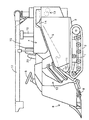
以下、本発明の実施例を図面に基づいて詳述する。図1はコンバインの全体側面図、図2は同平面図であり、図中1は左右一対の走行部材である走行クローラ2を装設するトラックフレーム、3は前記トラックフレーム1に架設する機台、4はフィードチェン5を左側に張架し扱胴6及び処理胴7を内蔵している脱穀部、8は刈刃9及び穀稈搬送機構10などを備える刈取部、11は刈取フレーム12を介して刈取部8を昇降させる油圧シリンダ、13は排藁チェン14終端を臨ませる排藁処理部、15は脱穀部4からの穀粒を揚穀筒16を介して搬入する穀物タンク、17は前記タンク15の穀粒を機外に搬出する排出オーガ、18は丸形操向ハンドル19及び運転席20などを備える運転台、21は運転席20下方に設けるエンジンであり、連続的に穀稈を刈取って脱穀するように構成している。   Embodiments of the present invention will be described below in detail with reference to the drawings. 1 is an overall side view of a combine, and FIG. 2 is a plan view thereof. In FIG. 1, 1 is a track frame on which a traveling crawler 2 as a pair of left and right traveling members is installed, and 3 is a machine base installed on the track frame 1 Reference numeral 4 denotes a threshing section that stretches the feed chain 5 on the left side and incorporates a handling cylinder 6 and a processing cylinder 7; 8, a reaping section that includes a cutting blade 9 and a culm conveying mechanism 10; and 11, a reaping frame 12. A hydraulic cylinder that raises and lowers the mowing unit 8 through 13, a waste disposal processing unit 13 that faces the end of the waste chain 14, 15 a grain tank that carries the grain from the threshing unit 4 through the milling cylinder 16, and 17 A discharge auger for unloading the grains in the tank 15, 18 is a driver's cab provided with a round steering handle 19 and a driver's seat 20, and 21 is an engine provided below the driver's seat 20. Configured to cut and thresh There.

また、図中22は走行クローラ2を駆動するミッションケース、23は運転台18左側に設けるサイドコラムであり、主変速レバー24・副変速レバー25・刈取クラッチレバー26・脱穀クラッチレバー27をサイドコラム23に設けている。   In the figure, 22 is a transmission case for driving the traveling crawler 2, and 23 is a side column provided on the left side of the cab 18. The main transmission lever 24, auxiliary transmission lever 25, mowing clutch lever 26, and threshing clutch lever 27 are connected to the side column. 23.

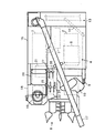
図3、図4に示す如く、前記ミッションケース22の一側に可変容量形油圧ポンプ28及び油圧モータ29で形成する1組の無段油圧変速機構30を設け、該変速機構30の変速入力用ポンプ軸31をエンジン2に連結させて、エンジン2出力を油圧変速機構30に伝達させると共に、ミッションケース22内に突出させるポンプ軸31に小径の伝達ギヤ32を係合軸支させ、PTO出力プーリ33を有するPTO出力軸34に伝達ギヤ32の動力を伝えるように構成している。   As shown in FIGS. 3 and 4, a set of continuously variable hydraulic transmission mechanism 30 formed of a variable displacement hydraulic pump 28 and a hydraulic motor 29 is provided on one side of the transmission case 22. The pump shaft 31 is connected to the engine 2 so that the output of the engine 2 is transmitted to the hydraulic transmission mechanism 30, and the transmission shaft 32 having a small diameter is supported on the pump shaft 31 that protrudes into the transmission case 22, and the PTO output pulley The power of the transmission gear 32 is transmitted to a PTO output shaft 34 having 33.

また、前記ミッションケース22内に突出させる油圧変速機構30のモータ軸35にサンギヤ36を係合軸支させ、前記の小径の伝達ギヤ32に大径のキャリヤギヤ37を常に噛合させ、サンギヤ36のボス部にキャリヤギヤ37を遊転軸支させるもので、キャリヤギヤ37に3枚のプラネタリギヤ38を軸39を介して回転自在に設け、サンギヤ36にプラネタリギヤ38を噛合させると共に、プラネタリギヤ38に噛合させるリングギヤ40を設け、各ギヤ36・38・40によって遊星ギヤ機構41を形成する。   Further, a sun gear 36 is engaged with a motor shaft 35 of a hydraulic transmission mechanism 30 that protrudes into the transmission case 22, and a large-diameter carrier gear 37 is always engaged with the small-diameter transmission gear 32. The carrier gear 37 is supported on a rotating shaft, and three planetary gears 38 are rotatably provided on the carrier gear 37 via a shaft 39. The planetary gear 38 is engaged with the sun gear 36, and the ring gear 40 engaged with the planetary gear 38 is provided. The planetary gear mechanism 41 is formed by the gears 36, 38, and 40.

さらに、前記サンギヤ36とミッションケース22に合成出力軸42の両端を回転自在に軸支させ、前記リングギヤ40を合成出力軸42に係合軸支させるもので、図11乃至図13に示す如く油圧変速機構30の油圧ポンプ28及び油圧モータ29の無段油圧変速出力である正逆回転出力と、伝達ギヤ32及びキャリヤギヤ37の回転出力(一方向の一定回転)とを、遊星ギヤ機構41のデフ作用によって合成し、ゼロ乃至最大速の一方向の回転力として合成出力軸42に伝える。   Further, both ends of the composite output shaft 42 are rotatably supported by the sun gear 36 and the transmission case 22, and the ring gear 40 is rotatably supported by the composite output shaft 42. As shown in FIGS. A forward / reverse rotation output, which is a continuously variable hydraulic shift output of the hydraulic pump 28 and the hydraulic motor 29 of the transmission mechanism 30, and a rotation output (constant rotation in one direction) of the transmission gear 32 and the carrier gear 37 are used as the differential of the planetary gear mechanism 41. It is synthesized by action and transmitted to the synthesized output shaft 42 as a rotational force in one direction from zero to the maximum speed.

また、前記合成出力軸42を1対のギヤ43を介して副変速ギヤ軸44に連結させると共に、副変速ギヤ部44aを構成する1対の低速ギヤ45及び高速ギヤ46を介して駐車ブレーキ47を有する駐車ブレーキ軸48に副変速ギヤ軸44を連結させ、左右サイドクラッチ49・50を有する左右サイドクラッチ軸51・52、左右伝達軸53・54を介して左右前車軸55・56に駐車ブレーキ軸48を連結させて、走行クローラ2の駆動スプロケット57を駆動して車体の前後進及び左右旋回を行うように構成している。   The combined output shaft 42 is connected to the auxiliary transmission gear shaft 44 through a pair of gears 43, and the parking brake 47 is connected through a pair of low-speed gear 45 and high-speed gear 46 constituting the auxiliary transmission gear portion 44a. The auxiliary transmission gear shaft 44 is connected to a parking brake shaft 48 having a left and right side clutch shafts 51 and 52 having left and right side clutches 49 and 50, and left and right front axles 55 and 56 via left and right transmission shafts 53 and 54. The shaft 48 is connected to drive the drive sprocket 57 of the traveling crawler 2 so that the vehicle body moves forward and backward and turns left and right.

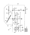
そして図3、図5乃至図9に示す如く、前記油圧ポンプ28及び油圧モータ29の斜板58・59に制御軸60・61を介して油圧変速操作アーム62・63を連結させ、該アーム62・63をロッドなどを介し主変速レバー24に連結させて、主変速レバー24の操作でもって斜板58・59の傾斜角を変更して合成出力軸42の回転制御を行うように構成している。   As shown in FIGS. 3 and 5 to 9, hydraulic shift operation arms 62 and 63 are connected to the swash plates 58 and 59 of the hydraulic pump 28 and the hydraulic motor 29 via control shafts 60 and 61, respectively. -63 is connected to the main speed change lever 24 via a rod or the like, and the rotation angle of the swash plates 58 and 59 is changed by the operation of the main speed change lever 24 to control the rotation of the composite output shaft 42. Yes.

そして、主変速レバー24を中立位置Nと前進最高速位置F2間で操作する場合には、油圧モータ29の斜板59の傾斜角θaを一定保持させた状態で油圧ポンプ28の斜板58の傾斜角のみを最大逆転角−αから最大正転角+α間で変化させて車体の移動速度を0から最高速度V2まで変速させる前進走行を行う一方、主変速レバー24を中立位置Nと後進最高速位置R間で操作する場合には、油圧ポンプ28の斜板58の傾斜角を最大逆転角−αに保った状態で、油圧モータ29の斜板59のみを一定傾斜角θaと低速側(斜板59を立てる方向)の一定傾斜角θbとの間で変化させて車速の移動速度を0から最高速度V1まで変速させる後進走行を行う。   When the main transmission lever 24 is operated between the neutral position N and the forward maximum speed position F2, the inclination angle θa of the swash plate 59 of the hydraulic motor 29 is kept constant and the swash plate 58 of the hydraulic pump 28 is maintained. Only the inclination angle is changed from the maximum reverse rotation angle -α to the maximum forward rotation angle + α to perform forward traveling in which the moving speed of the vehicle body is changed from 0 to the maximum speed V2, while the main transmission lever 24 is set to the neutral position N and the reverse maximum. When operating between the high speed positions R, only the swash plate 59 of the hydraulic motor 29 is kept at a constant inclination angle θa and a low speed side (with the inclination angle of the swash plate 58 of the hydraulic pump 28 kept at the maximum reverse rotation angle −α. The vehicle travels backward to change the moving speed of the vehicle speed from 0 to the maximum speed V1 by changing the angle between the swash plate 59 and the constant inclination angle θb.

つまり、図5、図9に示す如く、主変速レバー24を中立位置Nに操作し、油圧ポンプ28斜板58を傾斜角−α、油圧モータ29斜板59を傾斜角θaで油圧変速機構30を駆動するとき、図10(1)に示す如く、サンギヤ36は最高回転で時計回りに逆転してプラネタリギヤ38を反時計回りに自転させる動作を行わせると同時に、また伝達ギヤ32によってキャリヤギヤ37を回転させることにより、プラネタリギヤ38を時計方向に公転させて反時計回りに自転させる動作を行わせ、リングギヤ40の回転をゼロにし、合成出力軸42を停止維持する(図9のA位置、移動速度は0)。   That is, as shown in FIGS. 5 and 9, the main transmission lever 24 is operated to the neutral position N, the hydraulic pump 28 swash plate 58 is inclined at −α, and the hydraulic motor 29 swash plate 59 is inclined at the inclination angle θa. 10 (1), the sun gear 36 rotates in the clockwise direction at the maximum rotation and rotates the planetary gear 38 counterclockwise. At the same time, the carrier gear 37 is moved by the transmission gear 32. By rotating, the planetary gear 38 is revolved clockwise to rotate counterclockwise, the rotation of the ring gear 40 is made zero, and the combined output shaft 42 is stopped and maintained (position A, moving speed in FIG. 9). Is 0).

また図6に示す如く、主変速レバー24を前進1速位置F1に操作し、油圧ポンプ28の斜板58を傾斜角0(立設状態)、油圧モータ29の斜板59を傾斜角θaで油圧変速機構30を駆動するとき、図10(2)に示す如く、サンギヤ36は停止し、伝達ギヤ32によってキャリヤギヤ37を回転させ、プラネタリギヤ38を時計方向に自転させ乍ら時計方向に公転させ、伝達ギヤ32のギヤ動力により合成出力軸42を回転させる(図9のB位置、移動速度は前進V1位置で、最高効率状態)。   Further, as shown in FIG. 6, the main transmission lever 24 is operated to the first forward speed position F1, the swash plate 58 of the hydraulic pump 28 is tilted at an inclination angle 0 (upright state), and the swash plate 59 of the hydraulic motor 29 is tilted at an inclination angle θa. When the hydraulic transmission mechanism 30 is driven, as shown in FIG. 10 (2), the sun gear 36 is stopped, the carrier gear 37 is rotated by the transmission gear 32, and the planetary gear 38 is rotated in the clockwise direction while rotating in the clockwise direction. The combined output shaft 42 is rotated by the gear power of the transmission gear 32 (position B in FIG. 9, the moving speed is the forward V1 position and the maximum efficiency state).

さらに図7に示す如く、主変速レバー24を前進2速位置F2に操作し、油圧ポンプ28の斜板58を傾斜角+αで油圧モータ29の斜板59を傾斜角θaで油圧変速機構30を駆動するとき、図10(3)に示す如く、サンギヤ36は最高回転で反時計回りに正転し、プラネタリギヤ38を時計方向に自転させ乍ら伝達ギヤ32でキャリヤギヤ37を回転させることによって時計方向に公転させ、サンギヤ36からの油圧変速力と伝達ギヤ32動力を加算して合成出力軸42を回転させる(図9のC位置、移動速度は前進V2位置で、最高速状態)。   Further, as shown in FIG. 7, the main transmission lever 24 is operated to the forward second speed position F2, and the swash plate 58 of the hydraulic pump 28 is set to the inclination angle + α and the swash plate 59 of the hydraulic motor 29 is set to the inclination angle θa. When driving, as shown in FIG. 10 (3), the sun gear 36 rotates in the counterclockwise direction at the maximum rotation, the planetary gear 38 rotates in the clockwise direction, and the carrier gear 37 is rotated in the clockwise direction while rotating in the clockwise direction. , And the combined output shaft 42 is rotated by adding the hydraulic transmission force from the sun gear 36 and the power of the transmission gear 32 (position C in FIG. 9, the moving speed is the forward V2 position, the highest speed state).

また図8に示す如く、主変速レバー24を後進位置Rに操作し、油圧ポンプ28の斜板58を傾斜角−αで油圧モータ29の斜板59を傾斜角θb(θb<θa)で油圧変速機構30を駆動するとき、図10(1)の状態より油圧モータ29(サンギヤ36)の回転が減速し、合成出力軸42の回転は前進時の正転状態より逆転する(図9のD位置、移動速度は後進V1位置で後進走行状態)。   Further, as shown in FIG. 8, the main transmission lever 24 is operated to the reverse position R, and the swash plate 58 of the hydraulic pump 28 is hydraulically inclined at an inclination angle -α and the swash plate 59 of the hydraulic motor 29 is hydraulically inclined at an inclination angle θb (θb <θa). When the speed change mechanism 30 is driven, the rotation of the hydraulic motor 29 (sun gear 36) is decelerated from the state of FIG. 10 (1), and the rotation of the composite output shaft 42 is reversed from the normal rotation state during forward movement (D in FIG. 9). The position and moving speed are in the reverse travel state at the reverse V1 position).

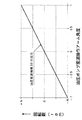
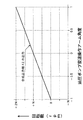
そして、例えば、一般的な入力動力100に対して、ギヤ32の損失が2で、油圧変速の損失が30の条件下において、図14のように、低速で走行時、エンジン2の入力動力を100とし、油圧伝達動力を50にした場合、油圧伝達動力の50がポンプ軸31に戻ってギヤ32側の伝達動力が150になると、ギヤ32の損失が3で、油圧変速機構30の損失が15となり、出力動力が82の割合で得られる。また、図15のように、前記油圧変速機構30の伝達動力をゼロにする中速で走行時、ギヤ32側の伝達動力が100になり、ギヤ32の損失が2となり、出力動力が98の割合で得られる。また、図16のように、高速で走行時、油圧伝達動力が40で、ギヤ32側の伝達動力が60の場合、ギヤ32の損失が1で、油圧変速機構30の損失が12となり、出力動力が87の割合で得られるもので、油圧モータ操作アーム63の角度を設定に保ち、例えば、図11のように、油圧ポンプ変速操作アーム62の角度を−1乃至0乃至1に変化させることにより、モータ軸35が−N乃至0乃至+N回転になるようにし、図12のように、前記アーム62の角度に関係なくギヤ32側をN回転させた場合、図13のように、前記アーム62の角度に対して合成出力軸42が0乃至2N回転になるように、ギヤ32・37及び遊星ギヤ機構41を組成して車体を前進走行させるように構成している。   And, for example, with respect to the general input power 100, the input power of the engine 2 is reduced when traveling at a low speed as shown in FIG. When the hydraulic transmission power is 50 and the hydraulic transmission power 50 returns to the pump shaft 31 and the transmission power on the gear 32 side becomes 150, the loss of the gear 32 is 3, and the hydraulic transmission mechanism 30 is lost. 15 and the output power is obtained at a rate of 82. Further, as shown in FIG. 15, when the vehicle travels at a medium speed where the transmission power of the hydraulic transmission mechanism 30 is zero, the transmission power on the gear 32 side is 100, the loss of the gear 32 is 2, and the output power is 98. Obtained in proportion. Further, as shown in FIG. 16, when traveling at high speed, when the hydraulic transmission power is 40 and the transmission power on the gear 32 side is 60, the loss of the gear 32 is 1, the loss of the hydraulic transmission mechanism 30 is 12, and the output The power is obtained at a ratio of 87, and the angle of the hydraulic motor operation arm 63 is maintained at a set value. For example, the angle of the hydraulic pump speed change operation arm 62 is changed from −1 to 0 to 1 as shown in FIG. Thus, when the motor shaft 35 is rotated from -N to 0 to + N and the gear 32 side is rotated N times regardless of the angle of the arm 62 as shown in FIG. The gears 32 and 37 and the planetary gear mechanism 41 are composed so that the vehicle body travels forward so that the combined output shaft 42 rotates 0 to 2N with respect to an angle of 62.

また、油圧ポンプ操作アーム62の角度が−1状態で、油圧モータ操作アーム63の角度を設定より中立側に戻すとき、合成出力軸42が逆転し0乃至N回転となるように設けて、車体を後進走行させるように構成している。   In addition, when the angle of the hydraulic pump operation arm 62 is −1 and the angle of the hydraulic motor operation arm 63 is returned to the neutral side from the setting, the composite output shaft 42 is reversely rotated so that 0 to N rotations are provided. Is configured to travel backward.

以上からも明らかなように、エンジン2の駆動力を伝える油圧変速機構30と伝達ギヤ32の各出力を合成して変速出力する複合変速機構64を備えた作業車において、1組の可変容量形の油圧ポンプ28及び油圧モータ29で油圧変速機構30を形成し、油圧ポンプ28の斜板58角制御によって複合変速機構64の合成出力軸42を正転方向に変速回転させると共に、油圧モータ29の斜板59角制御によって複合変速機構64の合成出力軸42を逆転方向に変速回転させるように設けたことによって、別途複雑な前後進切換機構(正逆転切換機構)など設ける必要なく可変容量形油圧モータ29の斜板59を調節するレバー或いはペダルの簡単な操作で前後進の切換えを容易に行うと共に、ゼロ発進時の出力トルクを容易に確保し微速走行性能を向上させ、しかも負荷の大きい作業においても高い動力伝達効率の出力を有効に利用して作業能率の向上など容易に図ることができる。   As is clear from the above, in a work vehicle including a composite transmission mechanism 64 that combines the outputs of the hydraulic transmission mechanism 30 for transmitting the driving force of the engine 2 and outputs of the transmission gear 32 to output the transmission, a set of variable displacement type The hydraulic transmission mechanism 30 is formed by the hydraulic pump 28 and the hydraulic motor 29, and the combined output shaft 42 of the composite transmission mechanism 64 is shifted in the normal rotation direction by the swash plate 58 angle control of the hydraulic pump 28. By providing the combined output shaft 42 of the composite speed change mechanism 64 so as to shift and rotate in the reverse direction by swash plate 59 angle control, there is no need to separately provide a complicated forward / reverse switching mechanism (forward / reverse switching mechanism). A simple operation of a lever or pedal that adjusts the swash plate 59 of the motor 29 makes it easy to switch between forward and backward movements, and easily secures output torque at the time of zero start, which is very slow. Improve line performance, yet it is possible to achieve such facilitate effectively improve work efficiency by using the output of the larger high in work efficiency of power transmission load.

また、油圧モータ29の斜板58角を一定保持させ、油圧ポンプ28の斜板58角を正逆に制御して複合変速機構64の合成出力軸42を正転方向で変速回転させることによって、油圧ポンプ28の斜板58角を単一のレバーなどによって操作するだけでの簡単な操作で合成出力軸42を一方向(正転)に変速回転させて、前進走行でのスムーズ且つ容易な変速などを容易に可能とさせることができる。   Further, the swash plate 58 angle of the hydraulic motor 29 is kept constant, the swash plate 58 angle of the hydraulic pump 28 is controlled to be forward and reverse, and the combined output shaft 42 of the composite transmission mechanism 64 is rotated in the forward direction. Smooth and easy shifting in forward travel by rotating the composite output shaft 42 in one direction (forward rotation) with a simple operation simply by operating the 58 swash plate angle of the hydraulic pump 28 with a single lever or the like. Etc. can be easily made possible.

さらに、油圧ポンプ28の斜板58角を逆転側最大出力位置(合成出力軸42が0回転)に保持させ、油圧モータ29の斜板58角を設定より中立側に制御して、複合変速機構64の合成出力軸42を逆転方向で変速回転させることによって、油圧モータ29の斜板58角を単一のレバーなどによって操作するだけの簡単な操作で合成出力軸42の反対側一方向(逆転)に変速回転させて、後進走行でのスムーズ且つ容易な変速などを容易に可能とさせることができる。   Further, the swash plate 58 angle of the hydraulic pump 28 is held at the reverse rotation side maximum output position (the combined output shaft 42 rotates 0 times), and the swash plate 58 angle of the hydraulic motor 29 is controlled to the neutral side from the setting, thereby combining the composite transmission mechanism. By rotating the 64 composite output shafts 42 in the reverse rotation direction, the swash plate 58 angle of the hydraulic motor 29 can be operated in one direction opposite to the composite output shaft 42 (reverse rotation) by a simple operation such as a single lever. ), The smooth and easy shifting in the reverse traveling can be easily performed.

また、油圧ポンプ28の斜板58角制御で前進での走行変速を行うと共に、油圧モータ29の斜板58角制御で後進での走行変速を行うことによって、1組の油圧ポンプ28及び油圧モータ29からなる油圧変速機構30のみを用いて、ゼロ発進や効率良好な出力などを確保した前後進走行を容易に可能とさせて、走行性能を向上させることができる。   In addition, a forward traveling shift is performed by the swash plate 58 angle control of the hydraulic pump 28, and a backward traveling shift is performed by the swash plate 58 angle control of the hydraulic motor 29, whereby one set of the hydraulic pump 28 and the hydraulic motor. By using only the hydraulic transmission mechanism 30 comprising 29, it is possible to easily perform forward / reverse traveling with zero start, efficient output, etc., and to improve traveling performance.

以上実施例から明らかなように本発明は、エンジン2の駆動力を伝える油圧変速機構30と伝達ギヤ32の各出力を合成して変速出力する複合変速機構64を備えた作業車において、1組の可変容量形の油圧ポンプ28及び油圧モータ29で油圧変速機構30を形成し、油圧ポンプ28の斜板58角制御によって複合変速機構64の合成出力軸42を正転方向に変速回転させると共に、油圧モータ29の斜板59角制御によって複合変速機構64の合成出力軸42を逆転方向に変速回転させるものであるから、別途複雑な前後進切換機構(正逆転切換機構)など設ける必要なく可変容量形油圧モータ29の斜板59を調節するレバー或いはペダルの簡単な操作で前後進の切換えを容易に行うと共に、ゼロ発進時の出力トルクを容易に確保し微速走行性能を向上させ、しかも負荷の大きい作業においても高い動力伝達効率の出力を有効に利用して作業能率の向上など容易に図ることができるものである。   As is apparent from the above-described embodiments, the present invention provides a working vehicle including a hydraulic transmission mechanism 30 that transmits the driving force of the engine 2 and a composite transmission mechanism 64 that combines the outputs of the transmission gear 32 and outputs the transmission. The variable displacement hydraulic pump 28 and the hydraulic motor 29 form a hydraulic transmission mechanism 30, and the combined output shaft 42 of the composite transmission mechanism 64 is shifted in the normal rotation direction by controlling the swash plate 58 angle of the hydraulic pump 28. Since the combined output shaft 42 of the composite transmission mechanism 64 is rotationally rotated in the reverse direction by controlling the swash plate 59 angle of the hydraulic motor 29, there is no need to provide a separate complicated forward / reverse switching mechanism (forward / reverse switching mechanism). A simple operation of a lever or pedal that adjusts the swash plate 59 of the hydraulic motor 29 makes it easy to switch between forward and backward travel, and easily secures the output torque at the time of zero start to Running performance is improved and yet as it can be easily achieved, such as improvement of the work efficiency by effectively utilizing the output of the high power transmission efficiency even in a large work load.

また、油圧モータ29の斜板58角を一定保持させ、油圧ポンプ28の斜板58角を正逆に制御して複合変速機構64の合成出力軸42を正転方向で変速回転させるものであるから、油圧ポンプ28の斜板58角を単一のレバーなどによって操作するだけでの簡単な操作で合成出力軸42を一方向(正転)に変速回転させて、前進走行でのスムーズ且つ容易な変速などを容易に可能とさせることができるものである。   Further, the swash plate 58 angle of the hydraulic motor 29 is held constant, and the swash plate 58 angle of the hydraulic pump 28 is controlled to be forward and reverse to rotate the composite output shaft 42 of the composite transmission mechanism 64 in the forward rotation direction. Therefore, the composite output shaft 42 can be shifted and rotated in one direction (forward rotation) with a simple operation simply by operating the swash plate 58 angle of the hydraulic pump 28 with a single lever or the like. Therefore, it is possible to easily change the speed.

さらに、油圧ポンプ28の斜板58角を逆転側最大出力位置に保持させ、油圧モータ29の斜板58角を設定より中立側に制御して、複合変速機構64の合成出力軸42を逆転方向で変速回転させるものであるから、油圧モータ29の斜板58角を単一のレバーなどによって操作するだけの簡単な操作で合成出力軸42の反対側一方向(逆転)に変速回転させて、後進走行でのスムーズ且つ容易な変速などを容易に可能とさせることができるものである。   Further, the swash plate 58 angle of the hydraulic pump 28 is held at the maximum reverse rotation output position, and the swash plate 58 angle of the hydraulic motor 29 is controlled to the neutral side from the setting, so that the composite output shaft 42 of the composite transmission mechanism 64 is rotated in the reverse rotation direction. Therefore, the swash plate 58 of the hydraulic motor 29 can be rotated in one direction (reverse rotation) opposite to the combined output shaft 42 by a simple operation such as operating a single lever. It is possible to easily make a smooth and easy shift in reverse travel.

また、油圧ポンプ28の斜板58角制御で前進での走行変速を行うと共に、油圧モータ29の斜板58角制御で後進での走行変速を行うものであるから、1組の油圧ポンプ28及び油圧モータ29からなる油圧変速機構30のみを用いて、ゼロ発進や効率良好な出力などを確保した前後進走行を容易に可能とさせて、走行性能を向上させることができるものである。   Further, the forward travel shift is performed by the swash plate 58 angle control of the hydraulic pump 28, and the reverse travel shift is performed by the swash plate 58 angle control of the hydraulic motor 29. By using only the hydraulic speed change mechanism 30 including the hydraulic motor 29, it is possible to easily perform forward / reverse traveling with zero start, efficient output, etc., and to improve traveling performance.

2 エンジン
28 油圧ポンプ
29 油圧モータ
30 油圧変速機構
42 合成出力軸
2 Engine 28 Hydraulic pump 29 Hydraulic motor 30 Hydraulic transmission mechanism 42 Composite output shaft

Claims (1)

エンジン(21)の動力を変速して出力する油圧変速機構(30)としての油圧ポンプ(28)及び油圧モータ(29)と、前記エンジン(21)の動力と前記油圧モータ(29)の変速出力とを合成する遊星ギヤ機構(41)、前記遊星ギヤ機構(41)の合成出力がゼロ乃至最大速の一方向の回転力として伝達される合成出力軸(42)、及びPTO出力軸(34)を有するミッションケース(22)とを備えた作業車において、
前記油圧モータ(29)のモータ軸(35)にサンギヤ(36)を係合軸支させ、前記サンギヤ(36)にキャリヤギヤ(37)を遊転軸支させ、前記キャリヤギヤ(37)にプラネタリギヤ(38)を回転自在に設け、前記サンギヤ(36)に前記プラネタリギヤ(38)を噛合させ、前記プラネタリギヤ(38)に噛合させるリングギヤ(40)を設け、前記合成出力軸(42)に前記リングギヤ(40)を係合軸支させ、前記サンギヤ(36)、前記プラネタリギヤ(38)及び前記リングギヤ(40)によって前記遊星ギヤ機構(41)を形成し、
前記油圧モータ(29)の変速出力と、前記エンジン(21)から前記キャリヤギヤ(37)に伝わった一方向の一定回転力とを合成して、ゼロ乃至最大速の一方向の回転力として前記リングギヤ(40)から前記合成出力軸(42)に伝えるように構成し、前記油圧ポンプ(28)のポンプ軸(31)で前記PTO出力軸(34)を駆動させるように構成する一方、
前記油圧ポンプ(28)の斜板傾斜角を最大逆転角にして前記サンギヤ(36)の回転速度を逆転最大回転速度にしたときに、前記キャリヤギヤ(37)の一方向の一定回転力を合成して前記リングギヤ(40)の回転をゼロにするように、前記キャリヤギヤ(37)及び前記遊星ギヤ機構(41)を組成している、
作業車。
A hydraulic pump (28) and a hydraulic motor (29) as a hydraulic transmission mechanism (30) for shifting and outputting the power of the engine (21), the power of the engine (21), and the shift output of the hydraulic motor (29) A planetary gear mechanism (41), a combined output shaft (42) to which a combined output of the planetary gear mechanism (41) is transmitted as a rotational force in one direction of zero to maximum speed, and a PTO output shaft (34) in agricultural work vehicle that includes a transmission case (22) having a,
A sun gear (36) is supported on the motor shaft (35) of the hydraulic motor (29) , a carrier gear (37) is supported on the sun gear (36 ) and a planetary gear (38) is supported on the carrier gear (37). ) Is rotatably provided, the sun gear (36) is engaged with the planetary gear (38), the ring gear (40) is engaged with the planetary gear (38), and the combined output shaft (42) is provided with the ring gear (40). The planetary gear mechanism (41) is formed by the sun gear (36), the planetary gear (38), and the ring gear (40).
The ring gear is generated as a rotational force in one direction from zero to the maximum speed by combining the shift output of the hydraulic motor (29) and the constant rotational force in one direction transmitted from the engine (21) to the carrier gear (37). (40) said configured to convey the combined output shaft (42) from, while configured to drive the PTO output shaft (34) in front Symbol pump shaft of the hydraulic pump (28) (31),
When the swash plate inclination angle of the hydraulic pump (28) is set to the maximum reverse rotation angle and the rotational speed of the sun gear (36) is set to the maximum reverse rotation speed, a constant rotational force in one direction of the carrier gear (37) is synthesized. The carrier gear (37) and the planetary gear mechanism (41) are composed so that the rotation of the ring gear (40) is zero.
Agricultural work vehicle.
JP2011173161A 2011-08-08 2011-08-08 Farm work vehicle Expired - Lifetime JP5295331B2 (en)

Priority Applications (1)

Application Number Priority Date Filing Date Title
JP2011173161A JP5295331B2 (en) 2011-08-08 2011-08-08 Farm work vehicle

Applications Claiming Priority (1)

Application Number Priority Date Filing Date Title
JP2011173161A JP5295331B2 (en) 2011-08-08 2011-08-08 Farm work vehicle

Related Parent Applications (1)

Application Number Title Priority Date Filing Date
JP2001299314A Division JP4988111B2 (en) 2001-09-28 2001-09-28 Combine

Related Child Applications (1)

Application Number Title Priority Date Filing Date
JP2012209301A Division JP5653981B2 (en) 2012-09-24 2012-09-24 Farm work vehicle

Publications (2)

Publication Number Publication Date
JP2011257007A JP2011257007A (en) 2011-12-22
JP5295331B2 true JP5295331B2 (en) 2013-09-18

Family

ID=45473370

Family Applications (1)

Application Number Title Priority Date Filing Date
JP2011173161A Expired - Lifetime JP5295331B2 (en) 2011-08-08 2011-08-08 Farm work vehicle

Country Status (1)

Country Link
JP (1) JP5295331B2 (en)

Family Cites Families (8)

* Cited by examiner, † Cited by third party
Publication number Priority date Publication date Assignee Title
JPS53120047A (en) * 1977-03-29 1978-10-20 Kubota Ltd Hydraulic, mechanical continuous transmission
JP2501060Y2 (en) * 1989-04-18 1996-06-12 株式会社神崎高級工機製作所 Power take-off mechanism for traveling vehicle
JPH0560202A (en) * 1991-08-26 1993-03-09 Seirei Ind Co Ltd Compound continuously variable transmission
JPH08170710A (en) * 1994-12-19 1996-07-02 Kubota Corp Mission structure of work machine
JP3070002B2 (en) * 1996-09-20 2000-07-24 本田技研工業株式会社 Continuously variable steering
JP3985875B2 (en) * 1996-10-17 2007-10-03 株式会社小松製作所 Hydraulic-mechanical transmission
JP4308950B2 (en) * 1998-10-27 2009-08-05 ヤンマー株式会社 Hydraulic-mechanical transmission
JP4789229B2 (en) * 2001-08-01 2011-10-12 ヤンマー株式会社 Rice transplanter

Also Published As

Publication number Publication date
JP2011257007A (en) 2011-12-22

Similar Documents

Publication Publication Date Title
JP4607001B2 (en) Traveling vehicle
JP4988111B2 (en) Combine
JP3868452B2 (en) Combine steering device
JP5295331B2 (en) Farm work vehicle
JP5653981B2 (en) Farm work vehicle
JP5825730B2 (en) Work vehicle
JP5580455B2 (en) Output control method for agricultural vehicles
JP3817251B2 (en) Power transmission device for combine
JP2002172946A (en) Tractor
JP5313957B2 (en) Harvester traveling transmission device
JP5823276B2 (en) Working machine
JP3363271B2 (en) Steering device for traveling crawlers on mobile agricultural machines
JP2007062543A (en) Running driving device for working machine
JP5808941B2 (en) Rice transplanter transmission
JP2008239030A (en) Traveling vehicle
JP4297327B2 (en) Work vehicle
JPH09202259A (en) Steering device for running work machine
JP3986080B2 (en) Traveling vehicle
JP2009090786A (en) Transmission for working vehicle
JP2008162522A (en) Power transmission mechanism of working vehicle
JP3988891B2 (en) Traveling vehicle
JP4529985B2 (en) Combine
JP4529986B2 (en) Combine
JP2009090784A (en) Transmission for working vehicle
JPH0524554A (en) Traveling device for working machine

Legal Events

Date Code Title Description
A977 Report on retrieval

Free format text: JAPANESE INTERMEDIATE CODE: A971007

Effective date: 20120719

A131 Notification of reasons for refusal

Free format text: JAPANESE INTERMEDIATE CODE: A131

Effective date: 20120725

A521 Written amendment

Free format text: JAPANESE INTERMEDIATE CODE: A523

Effective date: 20120924

A02 Decision of refusal

Free format text: JAPANESE INTERMEDIATE CODE: A02

Effective date: 20130109

A521 Written amendment

Free format text: JAPANESE INTERMEDIATE CODE: A523

Effective date: 20130408

A911 Transfer of reconsideration by examiner before appeal (zenchi)

Free format text: JAPANESE INTERMEDIATE CODE: A911

Effective date: 20130415

TRDD Decision of grant or rejection written
A01 Written decision to grant a patent or to grant a registration (utility model)

Free format text: JAPANESE INTERMEDIATE CODE: A01

Effective date: 20130605

A61 First payment of annual fees (during grant procedure)

Free format text: JAPANESE INTERMEDIATE CODE: A61

Effective date: 20130611

R150 Certificate of patent or registration of utility model

Ref document number: 5295331

Country of ref document: JP

Free format text: JAPANESE INTERMEDIATE CODE: R150

Free format text: JAPANESE INTERMEDIATE CODE: R150

S531 Written request for registration of change of domicile

Free format text: JAPANESE INTERMEDIATE CODE: R313531

R350 Written notification of registration of transfer

Free format text: JAPANESE INTERMEDIATE CODE: R350

R250 Receipt of annual fees

Free format text: JAPANESE INTERMEDIATE CODE: R250