JP5295194B2 - Incombustible tape - Google Patents
Incombustible tape Download PDFInfo
- Publication number
- JP5295194B2 JP5295194B2 JP2010215252A JP2010215252A JP5295194B2 JP 5295194 B2 JP5295194 B2 JP 5295194B2 JP 2010215252 A JP2010215252 A JP 2010215252A JP 2010215252 A JP2010215252 A JP 2010215252A JP 5295194 B2 JP5295194 B2 JP 5295194B2
- Authority
- JP
- Japan
- Prior art keywords
- layer
- adhesive
- tape
- nonflammable
- adhesive layer
- Prior art date
- Legal status (The legal status is an assumption and is not a legal conclusion. Google has not performed a legal analysis and makes no representation as to the accuracy of the status listed.)
- Expired - Fee Related
Links
Images


Landscapes
- Building Environments (AREA)
- Adhesive Tapes (AREA)
Abstract
Description
本発明は、不燃性テープに関する。特に、溶接の火花などが周囲に飛散しないように囲う、複数の金属薄板の隙間を塞ぐ不燃性テープの構造に関する。 The present invention relates to a nonflammable tape. In particular, the present invention relates to a structure of a nonflammable tape that closes gaps between a plurality of thin metal plates and surrounds so that welding sparks do not scatter around.
例えば、発電所では、施設の内外で溶接作業を実施するときに、溶接の火花などが周囲に飛散しないように、耐火性を有する複数の金属薄板で囲っている。又、これらの金属薄板の隙間を不燃性テープで塞いでいる。これにより、溶接の火花などが溶接箇所以外の設備に飛散することを防止している。 For example, in a power plant, when performing welding work inside and outside the facility, it is surrounded by a plurality of metal sheets having fire resistance so that welding sparks do not scatter around. Further, the gap between these metal thin plates is closed with a nonflammable tape. This prevents welding sparks and the like from being scattered in equipment other than the welding location.
このような不燃性テープは、接着性を必要とすると共に、「燃えない・熱に強い」、という不燃性が要求されている。しかし、従来の不燃性テープは、粘着層に有機系接着剤を有するため、不燃性を付与することが困難であった。 Such a nonflammable tape is required to have adhesiveness and to be nonflammable, “not burnable and resistant to heat”. However, since the conventional nonflammable tape has an organic adhesive in the pressure-sensitive adhesive layer, it has been difficult to impart nonflammability.
このような不具合を解消するため、ケイ酸マグネシウムシートと、テープ用粘着剤と、金属箔と、更には、中性紙とを積層することによって、不燃材料の発熱性試験に合格できる優れた不燃性を有すると共に、優れた平滑性も有する不燃性テープが開示されている(例えば、特許文献1参照)。 In order to eliminate such problems, excellent non-combustibility that can pass the exothermic test of non-combustible materials by laminating magnesium silicate sheet, tape adhesive, metal foil, and neutral paper A non-combustible tape having excellent smoothness is disclosed (for example, see Patent Document 1).
特許文献1による不燃性テープは、第一層の中性紙と、第二層のアルミニウム箔と、第三層のケイ酸マグネシウムシートと、第四層のテープ用粘着剤とを順次積層させて構成している。そして、ケイ酸マグネシウムシートの表面に金属箔の層を設けて、可燃性ガスを遮断すると共に、熱伝導性に優れたアルミニウム箔で熱を分散させて局所的な加熱にも強くした。更に、熱伝導性の小さいケイ酸マグネシウムシートによって、テープ用粘着剤への熱伝導を遮断して、可燃性ガスの発生を抑えられる、としている。特許文献1による不燃性テープは、不燃材料の発熱性試験に合格した、としている。
The nonflammable tape according to
図6は、発電所などで溶接作業を実施するときの従来の作業現場の配置図であり、図6(A)は、前記作業現場の平明図、図6(B)は、前記作業現場の斜視図である。図6を参照すると、溶接の火花Sなどが周囲に飛散しないように、耐火性を有する複数の金属薄板8などで囲っている。又、作業現場の床面も耐火性を有する複数の金属薄板8などを敷設している。そして、これらの金属薄板8・8などの隙間81は、不燃性テープ9で外側から塞がれている(養生されている)。
FIG. 6 is a layout diagram of a conventional work site when performing welding work at a power plant or the like, FIG. 6 (A) is a plain view of the work site, and FIG. 6 (B) is a diagram of the work site. It is a perspective view. Referring to FIG. 6, a plurality of
図6を参照すると、不燃性テープ9は、接着層91に金属箔などからなる不燃層92を積層している。そして、不燃性テープ9は、接着層91が貼付面となるように、一対の金属薄板8・8などの隙間81を外側から塞いでいる。
Referring to FIG. 6, in the
しかし、図6に示されるように、従来は、接着層91が一対の金属薄板8・8の隙間81を外側から塞いでいるので、溶接の火花Sが隙間81から進入して、接着層91が引火することが考えられる。そして、接着層91が引火することによって、周囲の設備に延焼することが懸念される。
However, as shown in FIG. 6, conventionally, since the
同様に、図7は、発電所などで溶接作業を実施するときの従来の作業現場の配置図であり、図7(A)は、前記作業現場の平明図、図7(B)は、前記作業現場の斜視図である。図7を参照すると、溶接の火花Sなどが周囲に飛散しないように、耐火性を有する複数の金属薄板8などで囲っている。又、作業現場の床面も耐火性を有する複数の金属薄板8などを敷設している。そして、これらの金属薄板8・8などの隙間81は、不燃性テープ9で内側から塞がれている(養生されている)。
Similarly, FIG. 7 is a layout diagram of a conventional work site when performing welding work at a power plant or the like, FIG. 7A is a plain view of the work site, and FIG. It is a perspective view of a work site. Referring to FIG. 7, a plurality of
図7を参照すると、不燃性テープ9は、接着層91に金属箔などからなる不燃層92を積層している。そして、不燃性テープ9は、接着層91が貼付面となるように、一対の金属薄板8・8などの隙間81を内側から塞いでいる。
Referring to FIG. 7, in the
しかし、図7に示されるように、従来は、接着層91が一対の金属薄板8・8の隙間81を内側から塞いでいるので、溶接の火花Sなどが接着層91に引火することが考えられる。そして、接着層91が引火することによって、隙間81から周囲の設備に延焼することが懸念される。
However, as shown in FIG. 7, conventionally, since the
溶接の火花などが金属板などの耐火材の隙間から進入しても、又は直接的に、引火を防止できる接着性を有する不燃性テープが求められている。そして、以上のことが本発明の課題といってよい。 There is a need for an incombustible tape having adhesiveness that can prevent ignition even when welding sparks enter through a gap in a refractory material such as a metal plate or directly. The above can be said to be the subject of the present invention.
本発明は、このような課題に鑑みてなされたものであり、火花などが耐火材の隙間から進入しても、又は直接的に、周囲への引火を防止できる接着性を有する不燃性テープを提供することを目的とする。 The present invention has been made in view of such problems, and an incombustible tape having adhesiveness that can prevent ignition to the surroundings even when a spark or the like enters from a gap of a refractory material. The purpose is to provide.
本発明者は、帯状に延びる不燃性テープの接着面の幅方向の中央部を引火が困難な不燃層で構成すると共に、この不燃層の両翼を接着が容易な接着層を配置することにより、これらの課題が解決可能なことを見出し、これに基づいて、以下のような新たな不燃性テープを発明するに至った。 The inventor comprises a nonflammable layer that is difficult to ignite at the center in the width direction of the bonding surface of the nonflammable tape extending in a strip shape, and by arranging an adhesive layer that can be easily bonded to both wings of the nonflammable layer, The present inventors have found that these problems can be solved, and based on this, have come up with the following new incombustible tape.
(1)本発明による不燃性テープは、引火が困難な不燃層と、この不燃層に積層され、接着が容易な接着面を有する接着層と、を備え、前記接着面の幅方向の中央部には、前記接着層を幅方向に略均等に分断するように、所定の幅を有して前記不燃層を長手方向に帯状に表出している。 (1) A nonflammable tape according to the present invention includes a nonflammable layer that is difficult to ignite, and an adhesive layer that is laminated on the nonflammable layer and has an adhesive surface that can be easily bonded, and a central portion in the width direction of the adhesive surface. The non-combustible layer has a predetermined width and is exposed in a strip shape in the longitudinal direction so as to divide the adhesive layer substantially evenly in the width direction.
(2)前記不燃層の中央部は、前記接着層の接着面から僅かに隆起していることが好ましい。 (2) It is preferable that the central portion of the non-combustible layer is slightly raised from the adhesive surface of the adhesive layer.
(3)前記接着層の接着面には、分断された前記接着層の幅方向の外側に前記不燃層を更に表出してもよい。 (3) On the adhesive surface of the adhesive layer, the incombustible layer may be further exposed outside in the width direction of the divided adhesive layer.
(4)前記接着層の接着面には、分断された前記接着層の幅方向の外側に表出された前記不燃層の長手方向に断続する部分接着層を配置してもよい。 (4) On the adhesive surface of the adhesive layer, a partial adhesive layer intermittent in the longitudinal direction of the incombustible layer that is exposed outside in the width direction of the divided adhesive layer may be disposed.
本発明による不燃性テープは、帯状に延びる不燃性テープの接着面の幅方向の中央部を引火が困難な不燃層で構成すると共に、この不燃層の両翼を接着が容易な接着層を配置しているので、金属板などの耐火材の隙間を不燃層の中央部で塞いで、接着層を耐火材に接着すれば、火花などが耐火材の隙間から進入しても、接着層の引火を防止できる。又、接着層への引火を防止でき、金属板などの耐火材の隙間から周囲に延焼することを防止できる。 The non-combustible tape according to the present invention comprises a non-combustible layer that is difficult to ignite at the center in the width direction of the adhesive surface of the non-combustible tape that extends in a strip shape, and an adhesive layer that is easy to adhere to both wings of the non-combustible layer. Therefore, if the gap of the refractory material such as a metal plate is closed at the center of the incombustible layer and the adhesive layer is bonded to the refractory material, even if a spark enters from the gap of the refractory material, the adhesive layer will ignite. Can be prevented. Further, it is possible to prevent the adhesive layer from being ignited and to prevent the fire from spreading through the gaps of the refractory material such as a metal plate.
以下、図面を参照して本発明を実施するための形態を説明する。
[第1実施形態]
[不燃性テープの構成]
最初に、本発明の第1実施形態による不燃性テープの構成を説明する。
Hereinafter, embodiments for carrying out the present invention will be described with reference to the drawings.
[First Embodiment]
[Composition of nonflammable tape]
Initially, the structure of the nonflammable tape by 1st Embodiment of this invention is demonstrated.
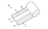
図1は、本発明の第1実施形態による不燃性テープの構成を示す斜視図であり、ロール状に巻回された不燃性テープの一部を引き延ばした状態図である。図2は、第1実施形態による不燃性テープの斜視図であり、接着面と反対の面から不燃性テープを観ている。図3は、第1実施形態による不燃性テープを用いて、溶接作業を実施するときの作業現場の配置を示す平面図である。 FIG. 1 is a perspective view showing a configuration of a nonflammable tape according to a first embodiment of the present invention, and is a state diagram in which a part of the nonflammable tape wound in a roll shape is stretched. FIG. 2 is a perspective view of the nonflammable tape according to the first embodiment, and the nonflammable tape is viewed from the surface opposite to the adhesive surface. FIG. 3 is a plan view showing an arrangement of a work site when performing a welding operation using the nonflammable tape according to the first embodiment.
図1から図3を参照すると、本発明の第1実施形態による不燃性テープ10は、不燃層1と接着層2を備えている。不燃層1は、引火が困難になっている。接着層2は、不燃層1に積層されており、接着が容易な接着面2aを有している。
1 to 3, a
図1に示されるように、不燃性テープ10は、接着面2aが内側になるように、通常、ロール状に巻回されている。そして、ロール状に巻回された不燃性テープ10を帯状に引き延ばして、例えば、一対の金属薄板8・8の隙間81を塞ぐことができる(図3参照)。
As shown in FIG. 1, the
例えば、不燃層1は、引火が困難な金属箔で構成されている。この金属箔には、アルミニウム、ステンレス、チタン、鋼、金、銀、白金、銅、真鍮、錫、ニッケルなどの金属の箔を用いることができる。又、接着層2には、様々な有機系接着剤、例えばアクリル溶剤型粘着剤やアクリル系エマルジョンなどを用いることができる。
For example, the
図1から図3を参照すると、接着層2の接着面2aには、不燃性テープ10の幅方向に略均等に分断された一対の接着層21・21を表出している。そして、接着面2aの中央部11には、所定の幅を有して、不燃層1を長手方向に帯状に表出している。
Referring to FIGS. 1 to 3, a pair of
図2を参照すると、不燃層1の中央部11は、接着層2の接着面2aから僅かに隆起している。不燃層1の中央部11は、一対の接着層21・21の接着面2aから僅かに隆起している、ということもできる。
Referring to FIG. 2, the
[不燃性テープの作用]
次に、第1実施形態による不燃性テープ10の作用及び効果を説明する。なお、図3において、図6又は図7で用いた符号と同じ符号を有する構成品は、その作用を同一とするので説明を割愛する場合がある。
[Action of nonflammable tape]
Next, the operation and effect of the
図3を参照すると、図6に示された不燃性テープ9に替えて、第1実施形態による不燃性テープ10を用いている。不燃性テープ10は、不燃層1の中央部11が一対の金属薄板8・8の隙間81を塞いでいる。又、不燃性テープ10は、一対の接着層21・21が隙間81を跨ぐように、一対の金属薄板8・8に接着している。
Referring to FIG. 3, the
図3を参照すると、不燃性テープ10は、一対の金属薄板8・8の隙間81を不燃層1の中央部11で塞ぎ、一対の接着層21・21が一対の金属薄板8・8に接着しているので、火花Sなどが隙間81から進入しても、不燃層1の中央部11で阻止されて、一対の接着層21・21の引火を防止できる。
Referring to FIG. 3, the
又、図2を参照すると、不燃層1の中央部11は、接着層2の接着面2aから僅かに隆起しているので、隙間81の両翼の金属薄板8・8に弾力をもって、密着できる。これにより、隙間81から進入してくる火花Sなどが一対の接着層21・21に到達することを防止できる。又、図7と同様に、金属薄板8・8の内側に不燃性テープ10を貼着した場合は、接着層2への引火を防止でき、金属薄板8・8の隙間81から周囲に延焼することを防止できる。
Referring to FIG. 2, the
[第2実施形態]
次に、本発明の第2実施形態による不燃性テープの構成及び作用を説明する。図4は、本発明の第2実施形態による不燃性テープの構成を示す斜視図である。なお、図4において、図1から図3で使用した符合と同じ符号を有する構成品は、その作用を同一とするので説明を割愛する場合がある。
[Second Embodiment]
Next, the configuration and operation of the nonflammable tape according to the second embodiment of the present invention will be described. FIG. 4 is a perspective view showing the configuration of the non-combustible tape according to the second embodiment of the present invention. In FIG. 4, the components having the same reference numerals as those used in FIGS. 1 to 3 have the same operation, and therefore the description thereof may be omitted.
図4を参照すると、本発明の第2実施形態による不燃性テープ20は、分断された一対の接着層21・21の幅方向の外側に、一対の不燃層12・12を接着層2の接着面2aに表出している。
Referring to FIG. 4, the
又、図4を参照すると、第2実施形態による不燃性テープ20に設けた一対の不燃層12・12は、不燃層1の中央部11と同様に、一対の接着層21・21の接着面2aから僅かに隆起している。
Referring to FIG. 4, the pair of
図3を参照して、不燃性テープ20は、不燃層1の中央部11が一対の金属薄板8・8の隙間81を塞ぐことができる。又、不燃性テープ20は、一対の接着層21・21が隙間81を跨ぐように、一対の金属薄板8・8に接着できる。
With reference to FIG. 3, in the
第2実施形態による不燃性テープ20は、一対の接着層21・21が引火する不測の事態が生じても、これらの接着層21・21の外側に配置された一対の不燃層12・12に阻止されて、不燃性テープ20の周囲への延焼を防止できるという、利点がある。
The
[第3実施形態]
次に、本発明の第3実施形態による不燃性テープの構成及び作用を説明する。図5は、本発明の第3実施形態による不燃性テープの構成を示す斜視図である。なお、図5において、図1から図4で使用した符合と同じ符号を有する構成品は、その作用を同一とするので説明を割愛する場合がある。
[Third Embodiment]
Next, the configuration and operation of the nonflammable tape according to the third embodiment of the present invention will be described. FIG. 5 is a perspective view showing the configuration of the non-combustible tape according to the third embodiment of the present invention. In FIG. 5, the components having the same reference numerals as those used in FIGS. 1 to 4 have the same operation, and thus the description thereof may be omitted.
図5を参照すると、本発明の第3実施形態による不燃性テープ30は、第2実施形態による不燃性テープ20の構成に加えて、分断された一対の接着層21・21の幅方向の外側に表出された不燃層12の長手方向に断続する部分接着層22を配置している。なお、部分接着層22は、不燃層12によって接着層21とは隔離されている。
Referring to FIG. 5, the
第3実施形態による不燃性テープ30は、第2実施形態による不燃性テープ20と同様な効果を奏する他に、接着層2の接着面2aには、部分接着層22を配置しているので、一対の金属薄板8・8への接着がより確実であるという、メリットがある。
Since the
本発明による不燃性テープは、溶接の火花などが周囲に飛散しないように囲う、複数の金属薄板の隙間を塞ぐ不燃性テープを開示したが、用途はこれに限定されない。本発明による不燃性テープは、例えば、壁装材や壁材などの建材の間を接合する不燃性テープとして用いることができる。 Although the non-combustible tape according to the present invention is disclosed as a non-combustible tape that closes gaps between a plurality of thin metal plates that surrounds welding sparks and the like so as not to scatter, the application is not limited thereto. The nonflammable tape according to the present invention can be used as, for example, a nonflammable tape that joins building materials such as wall covering materials and wall materials.
1 不燃層
2 接着層
2a 接着面
10 不燃性テープ
11 中央部(不燃層の中央部)
21・21 接着層(分断された一対の接着層)
DESCRIPTION OF
21.21 Adhesive layer (a pair of separated adhesive layers)
Claims (3)
引火が困難な不燃層と、
この不燃層に積層され、接着が容易な接着面を有する接着層と、を備え、
前記接着面の幅方向の中央部には、前記接着層を幅方向に均等に分断するように、所定の幅を有して前記不燃層を長手方向に帯状に表出していると共に、前記不燃層の中央部は、前記接着層の接着面から隆起し、
前記不燃層の中央部が一対の前記金属薄板の隙間を塞ぐと共に、一対の前記接着層が前記金属薄板の隙間を跨ぐように、一対の前記金属薄板に接着し、一対の前記接着層の引火を防止する不燃性テープ。 Incombustible tape that is used to seal the gap between multiple metal sheets from the opposite side of the welding spark so that the welding spark does not scatter around.
An incombustible layer that is difficult to ignite,
An adhesive layer that is laminated on the incombustible layer and has an adhesive surface that is easy to adhere,
At the center in the width direction of the adhesive surface, the non-combustible layer is exposed in a longitudinal direction with a predetermined width so as to divide the adhesive layer evenly in the width direction, and the non-combustible The central part of the layer is raised from the adhesive surface of the adhesive layer,
The incombustible layer is bonded to the pair of thin metal plates so that the center portion of the non-combustible layer closes the gap between the pair of thin metal plates, and the pair of adhesive layers straddles the gap between the thin metal plates. Incombustible tape to prevent.
Priority Applications (1)
| Application Number | Priority Date | Filing Date | Title |
|---|---|---|---|
| JP2010215252A JP5295194B2 (en) | 2010-09-27 | 2010-09-27 | Incombustible tape |
Applications Claiming Priority (1)
| Application Number | Priority Date | Filing Date | Title |
|---|---|---|---|
| JP2010215252A JP5295194B2 (en) | 2010-09-27 | 2010-09-27 | Incombustible tape |
Publications (2)
| Publication Number | Publication Date |
|---|---|
| JP2012067249A JP2012067249A (en) | 2012-04-05 |
| JP5295194B2 true JP5295194B2 (en) | 2013-09-18 |
Family
ID=46164888
Family Applications (1)
| Application Number | Title | Priority Date | Filing Date |
|---|---|---|---|
| JP2010215252A Expired - Fee Related JP5295194B2 (en) | 2010-09-27 | 2010-09-27 | Incombustible tape |
Country Status (1)
| Country | Link |
|---|---|
| JP (1) | JP5295194B2 (en) |
Families Citing this family (1)
| Publication number | Priority date | Publication date | Assignee | Title |
|---|---|---|---|---|
| CN110114429B (en) * | 2016-12-22 | 2021-09-28 | 3M创新有限公司 | Adhesive articles |
Family Cites Families (8)
| Publication number | Priority date | Publication date | Assignee | Title |
|---|---|---|---|---|
| JPS5713844Y2 (en) * | 1976-12-06 | 1982-03-20 | ||
| JPS60127334U (en) * | 1984-01-30 | 1985-08-27 | 富士商興株式会社 | pressure sensitive adhesive tape |
| JPS61180141U (en) * | 1985-04-26 | 1986-11-10 | ||
| JPS6327447U (en) * | 1986-08-04 | 1988-02-23 | ||
| JPH032292A (en) * | 1989-05-30 | 1991-01-08 | Masaya Takinami | Tacky adhesive device |
| JP2798634B2 (en) * | 1995-10-31 | 1998-09-17 | 株式会社スリオンテック | Protective tape for metal welding |
| JP2001335756A (en) * | 2000-05-29 | 2001-12-04 | Nitto Denko Corp | Pressure-sensitive adhesive tape and winding of pressure- sensitive adhesive tape |
| JP2009179664A (en) * | 2008-01-29 | 2009-08-13 | Nissho Kk | Adhesive tape and method of manufacturing the same |
-
2010
- 2010-09-27 JP JP2010215252A patent/JP5295194B2/en not_active Expired - Fee Related
Also Published As
| Publication number | Publication date |
|---|---|
| JP2012067249A (en) | 2012-04-05 |
Similar Documents
| Publication | Publication Date | Title |
|---|---|---|
| JP2010255792A (en) | Heat resistant packing member and fire spread preventing construction method | |
| JP5295194B2 (en) | Incombustible tape | |
| CN204141076U (en) | A kind of fireproof blocking layer | |
| JP5356113B2 (en) | Building outdoor panel structure | |
| WO2021149778A1 (en) | Fire extinguishing body | |
| JP2011158013A (en) | Fireproof treatment implement and fireproof treatment structure | |
| JP6517463B2 (en) | Fireproofing material | |
| JP4938359B2 (en) | Fireproof insulation panel | |
| TW200625513A (en) | Substrate and method for fabricating the same | |
| CN110041844A (en) | A kind of heat dissipation non-flammable adhesive tape | |
| CN208673753U (en) | A kind of environmental protection and safety type fireproof cable | |
| JP3122226U (en) | Sheet heating sheet | |
| JP3245262U (en) | fire extinguishing sheet | |
| CN202008863U (en) | Alumina cross-linked polyethylene flame-retardant cable | |
| CN202008857U (en) | Aluminum oxide fire-resistant cable | |
| CN202404979U (en) | Flame-retardant cable with halogen-free low-smoke flame-retardant polyolefin insulated jacket | |
| CN202404977U (en) | Calcium oxide antiflaming polyvinyl fluoride antiflaming cable | |
| CN202008859U (en) | Flame-retardant cable made of aluminum oxide and flame-retardant polyvinyl fluoride | |
| CN202404975U (en) | Halogen-free low-smoke flame retardant polyolefin chromium oxide flame-retardant cable | |
| CN213951080U (en) | Fire prevention band | |
| CN202404978U (en) | Low-smoke zero-halogen flame-retardant polyolefin insulating sheath flame-retardant cable | |
| JPH01256640A (en) | Extinguishable mat | |
| CN206570974U (en) | A kind of fire preventing steel structure for building | |
| CN202404976U (en) | Chromic oxide flame-retardant cable | |
| JP2010083039A (en) | Noncombustible laminated board |
Legal Events
| Date | Code | Title | Description |
|---|---|---|---|
| A977 | Report on retrieval |
Free format text: JAPANESE INTERMEDIATE CODE: A971007 Effective date: 20121116 |
|
| A131 | Notification of reasons for refusal |
Free format text: JAPANESE INTERMEDIATE CODE: A131 Effective date: 20121127 |
|
| A521 | Written amendment |
Free format text: JAPANESE INTERMEDIATE CODE: A523 Effective date: 20130115 |
|
| A131 | Notification of reasons for refusal |
Free format text: JAPANESE INTERMEDIATE CODE: A131 Effective date: 20130219 |
|
| A521 | Written amendment |
Free format text: JAPANESE INTERMEDIATE CODE: A523 Effective date: 20130412 |
|
| TRDD | Decision of grant or rejection written | ||
| A01 | Written decision to grant a patent or to grant a registration (utility model) |
Free format text: JAPANESE INTERMEDIATE CODE: A01 Effective date: 20130604 |
|
| A61 | First payment of annual fees (during grant procedure) |
Free format text: JAPANESE INTERMEDIATE CODE: A61 Effective date: 20130611 |
|
| R150 | Certificate of patent or registration of utility model |
Ref document number: 5295194 Country of ref document: JP Free format text: JAPANESE INTERMEDIATE CODE: R150 Free format text: JAPANESE INTERMEDIATE CODE: R150 |
|
| R250 | Receipt of annual fees |
Free format text: JAPANESE INTERMEDIATE CODE: R250 |
|
| R250 | Receipt of annual fees |
Free format text: JAPANESE INTERMEDIATE CODE: R250 |
|
| R250 | Receipt of annual fees |
Free format text: JAPANESE INTERMEDIATE CODE: R250 |
|
| LAPS | Cancellation because of no payment of annual fees |