JP5290430B2 - Layer material used with an insertion member half, and insertion member - Google Patents
Layer material used with an insertion member half, and insertion member Download PDFInfo
- Publication number
- JP5290430B2 JP5290430B2 JP2011542043A JP2011542043A JP5290430B2 JP 5290430 B2 JP5290430 B2 JP 5290430B2 JP 2011542043 A JP2011542043 A JP 2011542043A JP 2011542043 A JP2011542043 A JP 2011542043A JP 5290430 B2 JP5290430 B2 JP 5290430B2
- Authority
- JP
- Japan
- Prior art keywords
- layer material
- index means
- insertion member
- member half
- layer
- Prior art date
- Legal status (The legal status is an assumption and is not a legal conclusion. Google has not performed a legal analysis and makes no representation as to the accuracy of the status listed.)
- Active
Links
Images


Classifications
-
- H—ELECTRICITY
- H02—GENERATION; CONVERSION OR DISTRIBUTION OF ELECTRIC POWER
- H02G—INSTALLATION OF ELECTRIC CABLES OR LINES, OR OF COMBINED OPTICAL AND ELECTRIC CABLES OR LINES
- H02G15/00—Cable fittings
- H02G15/013—Sealing means for cable inlets
-
- F—MECHANICAL ENGINEERING; LIGHTING; HEATING; WEAPONS; BLASTING
- F16—ENGINEERING ELEMENTS AND UNITS; GENERAL MEASURES FOR PRODUCING AND MAINTAINING EFFECTIVE FUNCTIONING OF MACHINES OR INSTALLATIONS; THERMAL INSULATION IN GENERAL
- F16L—PIPES; JOINTS OR FITTINGS FOR PIPES; SUPPORTS FOR PIPES, CABLES OR PROTECTIVE TUBING; MEANS FOR THERMAL INSULATION IN GENERAL
- F16L5/00—Devices for use where pipes, cables or protective tubing pass through walls or partitions
- F16L5/02—Sealing
- F16L5/08—Sealing by means of axial screws compressing a ring or sleeve
-
- F—MECHANICAL ENGINEERING; LIGHTING; HEATING; WEAPONS; BLASTING
- F16—ENGINEERING ELEMENTS AND UNITS; GENERAL MEASURES FOR PRODUCING AND MAINTAINING EFFECTIVE FUNCTIONING OF MACHINES OR INSTALLATIONS; THERMAL INSULATION IN GENERAL
- F16L—PIPES; JOINTS OR FITTINGS FOR PIPES; SUPPORTS FOR PIPES, CABLES OR PROTECTIVE TUBING; MEANS FOR THERMAL INSULATION IN GENERAL
- F16L5/00—Devices for use where pipes, cables or protective tubing pass through walls or partitions
- F16L5/02—Sealing
- F16L5/10—Sealing by using sealing rings or sleeves only
-
- F—MECHANICAL ENGINEERING; LIGHTING; HEATING; WEAPONS; BLASTING
- F16—ENGINEERING ELEMENTS AND UNITS; GENERAL MEASURES FOR PRODUCING AND MAINTAINING EFFECTIVE FUNCTIONING OF MACHINES OR INSTALLATIONS; THERMAL INSULATION IN GENERAL
- F16L—PIPES; JOINTS OR FITTINGS FOR PIPES; SUPPORTS FOR PIPES, CABLES OR PROTECTIVE TUBING; MEANS FOR THERMAL INSULATION IN GENERAL
- F16L5/00—Devices for use where pipes, cables or protective tubing pass through walls or partitions
- F16L5/02—Sealing
- F16L5/14—Sealing for double-walled or multi-channel pipes
Landscapes
- Engineering & Computer Science (AREA)
- General Engineering & Computer Science (AREA)
- Mechanical Engineering (AREA)
- Installation Of Indoor Wiring (AREA)
- Laying Of Electric Cables Or Lines Outside (AREA)
- Cable Accessories (AREA)
- Insulating Bodies (AREA)
- Gasket Seals (AREA)
- Connector Housings Or Holding Contact Members (AREA)
Description
本発明は、請求項1の序文に係る挿入部材半体と共に用いる層材と、この層材を備える挿入部材半体とに関する。
The present invention relates to a layer material used with an insertion member half according to the preamble of
多くの異なる技術分野、高い重要性を有するところでは例えば貿易船、沖合のプラットフォーム、建造物といった分野において、火災、爆発、水漏れ等の場合の安全要求事項は高い。火災、水漏れ等の場合、火及び/又は水は、船、プラットフォーム又は建造物内で、多くはワイヤ、ケーブル又はパイプに沿って広がる。火及び/又は水が広がるのを止める又は遅らせるために、船、プラットフォーム又は建造物内の隔壁を貫通している部分で、各ワイヤ、ケーブル又はパイプは、確実な方法でシーリングされるべきである。 In many different technical fields, where they are of high importance, such as trade ships, offshore platforms, buildings, etc., the safety requirements in the event of a fire, explosion, water leak, etc. are high. In the event of a fire, water leak, etc., the fire and / or water spreads within the ship, platform or building, often along wires, cables or pipes. In order to stop or delay the spread of fire and / or water, each wire, cable or pipe should be sealed in a reliable manner in the part that penetrates the bulkhead in the ship, platform or building. .
ケーブル、ワイヤ又はパイプが通っている隔壁の領域をシーリングするために用いられる一般的な方策の一つとしては、隔壁の開口部に取り付けられる長方形の枠材の使用が挙げられる。このような枠材は、枠材にかかる予測される負荷や要求される安全レベルに応じて、鋼鉄、アルミニウム又はステンレスによって形成され、隔壁の材料や寸法に応じて、ねじ、ボルト又は溶接によって、隔壁中にしっかり固定される。隔壁を通る全てのケーブル、ワイヤ又はパイプは、枠材を貫通しており、枠材内の開口部をシーリングするために、枠材を通る各ケーブル、ワイヤ又はパイプの周囲に挿入ブロックが配置される。このような挿入ブロックは、2つのブロック半体から構成される。それぞれのブロック半体には、このブロックの一面を横切るようにして延びる半円形の溝が設けられており、それぞれの溝が互いに対向するように2つのブロック半体が合わせられたとき、円形の開口部が形成されるようになっている。 One common strategy used to seal the partition area through which cables, wires or pipes pass is the use of a rectangular frame attached to the partition opening. Such a frame material is formed of steel, aluminum or stainless steel according to the expected load applied to the frame material and the required safety level, and depending on the material and dimensions of the partition wall, by screws, bolts or welding, Firmly fixed in the bulkhead. All cables, wires or pipes that pass through the bulkhead pass through the frame, and an insertion block is placed around each cable, wire, or pipe that passes through the frame to seal the opening in the frame. The Such an insertion block consists of two block halves. Each block half is provided with a semi-circular groove extending across one surface of the block, and when the two block halves are combined so that each groove faces each other, An opening is formed.
枠材をシーリングするために、枠材内の各々のケーブル、ワイヤ又はパイプは、挿入ブロック内にぴったりはまって、枠材内に詰め込まれる。ブロックは、枠材内で層状に並んで詰め込まれ、ブロックの外寸は、枠材内に所定の数のブロックがちょうど収まるように選択される。これらブロックの層は、ブロックを枠材内の所望の位置に維持する金属板によって、隔てられている。枠材の上部に圧力印加装置が導入される前には、枠材は挿入ブロックの層でほぼ完全に埋め尽くされる。ブロック、金属板及び圧力印加装置の全てが枠材内の適切な位置にあるとき、圧力印加装置は起動され、枠材内で圧力がブロック上に加えられる。圧力は、弾性ブロックを僅かに変形させ、枠材内の残った空間を密閉する。挿入ブロックの長方形の横断面は、さもなければ非常に困難であったケーブル、ワイヤ又はパイプの実質的な円形の横断面の周囲をシーリングすることを可能にする。 In order to seal the frame material, each cable, wire or pipe within the frame material fits within the insertion block and is packed into the frame material. The blocks are packed in layers within the frame material, and the outer dimensions of the blocks are selected such that a predetermined number of blocks just fit within the frame material. These layers of blocks are separated by a metal plate that maintains the blocks in the desired position within the frame. Before the pressure application device is introduced on top of the frame material, the frame material is almost completely filled with layers of insert blocks. When the block, metal plate and pressure applicator are all in the proper position within the frame, the pressure applicator is activated and pressure is applied on the block within the frame. The pressure slightly deforms the elastic block and seals the remaining space in the frame. The rectangular cross section of the insertion block makes it possible to seal around a substantially circular cross section of a cable, wire or pipe that was otherwise very difficult.
しかしながら、各ケーブル、ワイヤ又はパイプの周囲に確実なシーリングを与えるためには、溝の半径は、ケーブル、ワイヤ又はパイプの外径とほぼ正確に対応しなければならない。このため、異なる大きさの開口部を有する多くのブロックが用いられ得る。あるいは、例えば特許文献1に開示されているタイプの挿入ブロックが用いられる。このタイプの挿入ブロックは、ブロックの開口部内に合わされた多くの薄い層材を有している。1つ又は複数の層材を開口部から取り除くことによって、開口部の半径は、個別のケーブル、ワイヤ又はパイプに合わせられ得る。
However, in order to provide a reliable seal around each cable, wire or pipe, the radius of the groove must correspond approximately exactly to the outer diameter of the cable, wire or pipe. For this reason, many blocks with different sized openings can be used. Alternatively, for example, an insertion block of the type disclosed in
しかしながら、調節可能な挿入ブロックは、枠材内の開口部の要求される密閉度を確保するために、挿入ブロックの開口部とケーブル、ワイヤ又はパイプの外表面との間の取り付けをきつくしなければならず、開口部からちょうど適切な数の層材を取り外さなければ、要求される密閉度は達成されないことになるという、一つの重大な欠点を有する。 However, the adjustable insert block must tighten the attachment between the insert block opening and the outer surface of the cable, wire or pipe to ensure the required tightness of the opening in the frame. It has one serious drawback that the required degree of sealing will not be achieved unless just the right number of layers are removed from the opening.
したがって、枠材を貫通しているケーブル、ワイヤ又はパイプが適切にシーリングされないというリスクを低減する順応性のある挿入ブロックの要求がある。 Accordingly, there is a need for a flexible insertion block that reduces the risk that a cable, wire or pipe passing through the frame will not be properly sealed.
独立請求項1及び5に記載される本発明は、上記の問題を低減させる順応性のある挿入部材半体を提供する。
The invention as defined in the
これは、挿入部材半体における本発明による取り外し可能に配置された層材によって達成される。枠材中のケーブル、ワイヤ又は管の周りのシーリングをする挿入部材半体と組み合わせて用いるそれぞれの層材は、第1の端部と第2の端部とを有する細長い円弧形状を有しており、前記層材の前記第1の端部と前記第2の端部とのうち少なくとも一方に配置された少なくとも1つのインデックス手段が設けられていることを特徴とする。 This is achieved by the releasably disposed layer material according to the invention in the insert half. Each layer material used in combination with an insertion member half that seals around a cable, wire, or tube in the frame has an elongated arc shape having a first end and a second end. And at least one index means disposed at least one of the first end and the second end of the layer material is provided.
インデックス手段は、作業者に、特定のケーブル、ワイヤ又は管の寸法に対して可能な最適なシーリングを達成するためにいくつの層材を取り除くべきかの指標を与える。これは、大きな利点を有する。なぜなら、シーリングされる必要があるケーブル、ワイヤ又は管の周囲の挿入部材半体の調整の際、作業者が挿入部材半体の溝内の層材を適切な数だけ取り除かないという危険性を大幅に減らすことができるからである。多すぎる又は少なすぎる層材が取り外される場合、例えば火災や爆発の際に深刻な被害をもたらし得る、要求される密閉度が達せされないことになり得る。 The indexing means gives the operator an indication of how many layers to remove to achieve the optimum sealing possible for a particular cable, wire or tube dimension. This has great advantages. Because when adjusting the insert half around a cable, wire or tube that needs to be sealed, the risk of the operator not removing an appropriate number of layers in the groove of the insert half This is because it can be reduced. If too much or too little layer material is removed, the required degree of sealing, which can cause severe damage, for example in the event of a fire or explosion, may not be achieved.
本発明の別の利点は、挿入部材半体が枠材中に詰め込まれた後もインデックス手段が見えるので、取り付けに関する将来の検査を容易にすることである。このことは、この種の安全設備において、要求される取り付けの安全レベルを確保するために、定期的な基礎検査が行われるので、大きな利点を有する。本発明は、これらの検査をより正確にし、かつこれら検査に要する時間を短縮することになる。 Another advantage of the present invention is that it facilitates future inspection of the mounting, since the index means are visible after the insert half is packed into the frame. This has a great advantage in this kind of safety installation, since periodic basic inspections are carried out in order to ensure the required safety level of installation. The present invention will make these tests more accurate and reduce the time required for these tests.
好ましい本発明の一実施形態では、層材には、第1の端部と第2の端部とにインデックス手段が設けられている。この実施形態は、インデックス手段が、挿入部材半体が見られる方向から独立して認識されやすいので、特定のケーブル、ワイヤ又は管の寸法に対する挿入部材半体の調整を容易にする。 In a preferred embodiment of the present invention, the layer material is provided with index means at the first end and the second end. This embodiment facilitates adjustment of the insert member half for a particular cable, wire or tube dimension, as the index means is easily recognized independently of the direction in which the insert member half is viewed.
好ましい本発明の一実施形態では、インデックス手段は、層材の端部から延出している。層材の端部から延出しているインデックス手段を有することによって、インデックス手段の大きさは大きくされ得るし、その結果、取り付けを行う作業者によってより認識され易くなる。 In a preferred embodiment of the invention, the index means extend from the end of the layer material. By having the index means extending from the end of the layer material, the size of the index means can be increased, and as a result, it can be more easily recognized by the operator performing the installation.
好ましい本発明の一実施形態では、インデックス手段は、層材の端部から半径方向に延出している。この実施形態は、挿入部材半体の端面から大きくはみ出したインデックス手段を有することなく、インデックス手段の半径方向の大きさを大きくすることを可能にする。 In a preferred embodiment of the invention, the index means extend radially from the end of the layer material. This embodiment makes it possible to increase the size of the index means in the radial direction without having the index means protruding greatly from the end face of the insertion member half.
さらに、本発明は、枠材中のケーブル、ワイヤ又は管の周囲のシーリングをするための同様の挿入部材半体と組み合わせて用いるための挿入部材半体に関する。挿入部材半体は、
少なくとも1つの実質的に平らな第1の端面、第1の端面と平行な実質的に平らな第2の端面、及び第1の端面と第2の端面との間に延びる少なくとも1つの実質的に平らな側面を有する挿入部材本体と、
第1の端面から第2の端面まで延びる側面にある半円形の溝と、
を備え、
前記溝の半径を可変にするために、上記の複数の層材が前記半円形の溝内に取り外し可能に配置されていることを特徴とする。
The invention further relates to an insert member half for use in combination with a similar insert member half for sealing around cables, wires or tubes in a frame. Insert member half
At least one substantially flat first end face, a substantially flat second end face parallel to the first end face, and at least one substantially extending between the first end face and the second end face; An insertion member body having a flat side surface;
A semicircular groove on a side surface extending from the first end surface to the second end surface;
With
In order to make the radius of the groove variable, the plurality of layer materials are detachably disposed in the semicircular groove.
この挿入部材半体は、同様の挿入部材半体と組み合わせて用いられる際に、枠材を貫通するケーブル、ワイヤ又はパイプの不適切なシーリングという危険性を減少させる、非常に順応性のある挿入部材半体である。なぜなら、挿入ブロックは、複数の異なるケーブル、ワイヤ又は管の直径に容易に調整され得るし、溝内に取り外し可能に配置された層材のそれぞれのインデックス手段は、可能な最適なシーリングを達成するために取り除くべき層材の数についての指標を与えるからである。 This insert half is a very compliant insert that reduces the risk of improper sealing of cables, wires or pipes through the frame when used in combination with a similar insert half. It is a half member. Because the insertion block can be easily adjusted to a plurality of different cable, wire or tube diameters, each indexing means of the layer material removably arranged in the groove achieves the best possible sealing This is because it gives an index about the number of layer materials to be removed.
挿入部材半体の一実施形態では、異なる層材のインデックス手段は、異なる層材と関係するインデックス手段が溝の外周の周りに並んで配置されるように、層材の外周の周りの異なる場所に配置されている。この実施形態は、インデックス手段が互いに重なり合わず、挿入部材半体の調整を容易にするものであり、インデックス手段の好ましい配置を与える。 In one embodiment of the insertion member half, the index means of the different layer materials are located at different locations around the outer periphery of the layer material such that the index means associated with the different layer materials are arranged side by side around the outer periphery of the groove. Is arranged. This embodiment facilitates the adjustment of the insertion member halves without the indexing means overlapping each other and provides a preferred arrangement of the indexing means.
挿入部材半体の一実施形態では、挿入部材半体は、8つの層材を備える。取り外し可能な層材の端部におけるインデックス手段の幅は、層材の外周の8分の1以下である。この実施形態に係る挿入部材半体は、溝の直径の調節範囲について要求される順応性を与え、互いに重なり合うことなく容易に認識される十分な大きさのインデックス手段を確保する。 In one embodiment of the insert member half, the insert member half comprises eight layer members. The width of the index means at the end of the removable layer material is 1/8 or less of the outer circumference of the layer material. The insert half according to this embodiment provides the required flexibility for the adjustment range of the diameter of the groove and ensures a sufficiently large index means which can be easily recognized without overlapping each other.
挿入部材半体の一実施形態では、異なる層材のインデックス手段は、異なる色を有する。本発明のこの実施形態は、異なる層材の識別と選択とをさらに容易にする。 In one embodiment of the insertion member half, the index means of the different layer materials have different colors. This embodiment of the present invention further facilitates identification and selection of different layer materials.
挿入部材半体の一実施形態では、インデックス手段とこのインデックス手段が付属する層材とが同一色である。層材全体及びインデックス手段に異なる色を用いることで、異なる層材の識別と選択とをさらに容易にする。 In one embodiment of the half insert member, the index means and the layer material to which the index means is attached are the same color. By using different colors for the whole layer material and the index means, the identification and selection of different layer materials is further facilitated.
挿入部材半体の一実施形態では、各々のインデックス手段は、挿入部材半体の端面のうち一方又は両方に付された目に見える又は知覚可能な異なる記号を有する。この実施形態は、異なる層材の相互の識別を容易にし、完全に光がない場合にも、異なる層材と関連する記号を知覚して作業者が取り付け作業を行うことも可能にする。 In one embodiment of the insertion member half, each index means has a different visible or perceptible symbol applied to one or both of the end faces of the insertion member half. This embodiment facilitates the mutual identification of the different layer materials and also allows the operator to perform the installation work by perceiving the symbols associated with the different layer materials even in the absence of complete light.
挿入部材半体の一実施形態では、挿入部材本体は、実質的に直方体形状又は半円筒形状をしている。これらの挿入部材本体の形状によって、ケーブル、ワイヤ又は管の周囲で同様の挿入部材本体が組み合わされて用いられるとき、直方体形状又は円筒形状の何れかになることになる。枠材に容易に詰め込まれるので、直方体形状は四角形の枠材を用いるときに好ましく、円筒形状は円形の枠材を用いるときに好ましい。 In one embodiment of the insertion member half, the insertion member body has a substantially rectangular parallelepiped or semi-cylindrical shape. Depending on the shape of these insertion member main bodies, when similar insertion member main bodies are used in combination around a cable, a wire, or a tube, they will have either a rectangular parallelepiped shape or a cylindrical shape. The rectangular parallelepiped shape is preferable when a rectangular frame material is used, and the cylindrical shape is preferable when a circular frame material is used because it is easily packed into the frame material.
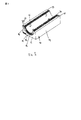
図1に、本発明の一実施形態に係る挿入部材半体10を示す。挿入部材半体は、実質的に直方体形状を有する挿入部材本体11を有する。挿入部材本体11は、第1の端面12と、第2の端面13と、3つの外面14と、図示しないケーブル、ワイヤ又は管の周りに合わせたときに2つ目の挿入部材半体の同様の表面と接する2つの表面15とを有する。2つの接触表面15は、挿入部材半体の中心に配置され、第1の端面12から第2の端面13まで延びる半円形の溝16の対向した両側に沿って、第1の端面12から第2の端面13まで延びる。
FIG. 1 shows an insertion member half 10 according to an embodiment of the present invention. The insertion member half has an insertion member body 11 having a substantially rectangular parallelepiped shape. The insertion member body 11 is similar to the second insertion member half when the first end surface 12, the
挿入部材半体10は、隔壁中に取り付けられる枠材を貫通させられるケーブル、ワイヤ又は管を対象とする。ケーブル、ワイヤ又は管は、ケーブル、ワイヤ又は管が2つの挿入部材半体10の溝16内に納められるような方法で同様の挿入部材半体が1つ目の挿入部材半体10と対向するように配置される前に、1つ目の挿入部材半体10の溝16内に配置される。ケーブル、ワイヤ又は管の周りに合わされた2つの挿入部材半体を、挿入ブロックと称することにする。挿入ブロックは、他の挿入ブロックとともに隔壁中に取り付けられる枠材内に詰め込まれる。 The insertion member half 10 is intended for a cable, a wire, or a tube that can be passed through a frame member that is mounted in a partition wall. A cable, wire or tube is similar to the first insert member half 10 such that the cable, wire or tube fits in the groove 16 of the two insert member halves 10. Before being placed in the groove 16 of the first half of the insert member 10. Two insertion member halves fitted around a cable, wire or tube will be referred to as an insertion block. The insertion block is packed in a frame member that is mounted in the partition wall together with other insertion blocks.
ケーブル、ワイヤ又は管の周りの要求される密閉度を確保するために、挿入部材半体10の溝16と挿入ブロックを通るケーブル、ワイヤ又は管の外表面との間がぴったりと合うことが重要である。このため挿入部材半体10には、特定のケーブル、ワイヤ又は管の直径に溝16の半径を調節することができるように、溝16内に取り外し可能に配置されている8つの別々の層材20が設けられている。 In order to ensure the required tightness around the cable, wire or tube, it is important that the groove 16 of the insert member half 10 and the outer surface of the cable, wire or tube passing through the insert block fit closely. It is. Thus, the insert member half 10 includes eight separate layers that are removably disposed within the groove 16 so that the radius of the groove 16 can be adjusted to the diameter of a particular cable, wire or tube. 20 is provided.
これら層材20は、挿入部材半体10の溝16に合わせて細長い円弧状の形状をしている。各層材20は、隣接した層材20内に対応する、又は溝16内に隣接して配置された層材ならば挿入部材半体の溝16に対応する、特定の予め決められた半径を有している。隣接した層材及び挿入部材半体の溝との要求されるぴったりとした嵌合を確保するために、層材の半径は、一番上の層材に向けて減少している。
These
図3に、1つの層材20を図示する。図1及び2に示す8つの層材の全ては、実質的に同じ形状を有しており、円弧のような形状の細長い層材本体21と、第1の端部22と、第2の端部23とを備えている。
FIG. 3 illustrates one
層材の厚さは、挿入部材半体が用いられる対象とするケーブル、ワイヤ又は管の要求される直径に合わせて選択される。例えば、要求される直径の差がそれぞれ1mmのとき、各層材は厚さ0.5mmであり、要求される直径の差がそれぞれ2mmのとき、各層材は厚さ1mmである。図示された挿入部材半体は、8つの異なる層材を有しているが、層材の数は、挿入部材半体及び挿入ブロックの調節範囲を増減させるために変更され得る。 The thickness of the layer material is selected according to the required diameter of the cable, wire or tube for which the insert half is to be used. For example, when each required difference in diameter is 1 mm, each layer material has a thickness of 0.5 mm, and when each required difference in diameter is 2 mm, each layer material has a thickness of 1 mm. Although the illustrated insert half has eight different layers, the number of layers can be varied to increase or decrease the adjustment range of the insert half and insert block.
各層材には、層材20の両端部22,23に配置されたインデックス手段30が設けられている。インデックス手段は、層材20の各端部22,23から半径方向外方に延びており、インデックス手段の外側端に向けて僅かに幅が増していく小さなタブの形をしている。インデックス手段の大きさは、枠材中に挿入ブロックを取り付ける作業者が容易に認識できるのに十分な大きさであるべきである。さらにインデックス手段の大きさは、ケーブル、ワイヤ又は管の特定の直径又は半径によって用いられるべき層材を示す数字や記号を印刷したり形成したりすることができるような大きさであるべきである。図2において、インデックス手段の1つは、あり得る記号の一例としての数字16が付されている。その他の選択肢として、異なるインデックス手段は異なる色とし、1つの色がある特定のケーブル、ワイヤ又は管の直径又は半径に対応するようにする。異なる色が層材を識別するために用いられるとき、異なる層材の識別をさらに容易にするために、層材全体がインデックス手段として同じ色に作られることが好ましい。これら2つの選択肢は、もちろん組み合わされてもよい。
Each layer material is provided with index means 30 arranged at both ends 22 and 23 of the
異なる層材のインデックス手段30は、溝内に配置されるときに、互いに重ならないように溝の外周の周りに並んで配置されるように、層材の円周に沿って異なる位置に配置される。 The different layer material index means 30 are arranged at different positions along the circumference of the layer material so that they are arranged side by side around the outer periphery of the groove so as not to overlap each other when arranged in the groove. The
本発明の図示された実施形態では、挿入部材半体10の両端面には、溝16の周りに切り欠き部17が設けられている。半径方向に延びているインデックス手段30がインデックス手段30の半径方向長さと同じ半径方向長さを有する切り欠き部17内に位置するように、溝16内に取り外し可能に配置された層材20は、溝16と同じ長さを有し、溝16と切り欠き部17との間の縁にある端部を有する。
In the illustrated embodiment of the present invention, notches 17 are provided around the groove 16 on both end faces of the insert member half 10. The
各層材には、層材本体21の外側表面の異なる位置に配置された円形の突起部23と、層材本体21の内側表面にある円形の凹部24とが設けられている。同様の円形の凹部は、挿入部材本体11に取り外し可能に配置された層材20のために、挿入部材本体11の溝16にも設けられている。これらの突起部23と凹部24とは、1つの層材の円形の突起部23が隣接する層材の円形の凹部24に圧入部を構成するように、所定の位置に配置されている。これら圧入部は、挿入部材半体10の溝16内に取り外し可能に配置された層材を保持する。
Each layer material is provided with a
本発明の1つの目下好ましい実施形態をここに記載したが、本発明は、これに限定されず、次に示す特許請求の範囲に含まれる種々のそして全ての改良及び変形を網羅しそれらを含むことを理解されたい。
以下に本願出願の当初の特許請求の範囲に記載された発明を付記する。
[1]
枠材中のケーブル、ワイヤ又は管の周囲のシーリングをするための挿入部材半体(10)と組み合わせて用いるための層材(20)であって、前記層材(20)は、第1の端部(21)と第2の端部(22)とを有する細長い円弧形状を有しており、
前記層材(20)には、前記層材(20)の前記第1の端部(21)と前記第2の端部(22)とのうち少なくとも一方に配置された少なくとも1つのインデックス手段(30)が設けられていることを特徴とする層材。
[2]
前記層材(20)には、前記第1の端部(21)と前記第2の端部(22)とに前記インデックス手段(30)が設けられている[1]に記載の層材。
[3]
前記インデックス手段(30)は、前記層材(20)の前記第1の端部(21)と前記第2の端部(22)とのうち少なくとも一方から延出している[1]又は[2]に記載の層材。
[4]
前記インデックス手段(30)は、前記層材(20)の前記第1の端部(21)と前記第2の端部(22)とのうち少なくとも一方から半径方向に延出している[1]、[2]又は[3]に記載の層材。
[5]
枠材中のケーブル、ワイヤ又は管の周囲のシーリングをするための同様の挿入部材半体と組み合わせて用いるための挿入部材半体(10)であって、前記挿入部材半体(10)は、
少なくとも1つの第1の端面(12)、前記第1の端面(12)と実質的に平行な第2の端面(13)、及び前記第1の端面(12)と前記第2の端面(13)との間に延びる少なくとも1つの側面(15)を有する挿入部材本体(11)と、
前記第1の端面(12)から前記第2の端面(13)まで延びる前記側面(15)にある半円形の溝(16)と、
を備え、
[1]乃至[4]のうち何れか1の層材(20)の複数個が、前記溝(16)の半径を可変にするために、前記半円形の溝(16)中に取り外し可能に配置されている、
ことを特徴とする挿入部材半体。
[6]
異なる層材(20)の前記インデックス手段(30)は、異なる層材(20)と関係するインデックス手段(30)が前記溝(16)の外周の周りに並んで配置されるように、前記層材(20)の外周の周りの異なる場所に配置されている[5]に記載の挿入部材半体。
[7]
前記挿入部材半体(10)は、8つの層材(20)を備え、取り外し可能な前記層材(20)の端部の前記インデックス手段(30)の幅は、前記層材(20)の外周の8分の1以下である[5]又は[6]に記載の挿入部材半体。
[8]
異なる層材(20)の前記インデックス手段(30)は異なる色を有する[5]、[6]又は[7]に記載の挿入部材半体。
[9]
前記インデックス手段(30)及びこのインデックス手段(30)が付属する前記層材(20)は同一色である[5]、[6]、[7]又は[8]に記載の挿入部材半体。
[10]
各々の前記インデックス手段(30)は、前記挿入部材半体(10)の前記第1の端面(12)及び前記第2の端面(13)のうち一方又は両方に付された異なる記号を有する[5]乃至[9]のうち何れか一に記載の挿入部材半体。
[11]
前記挿入部材本体(11)は、実質的に直方体形状又は半円筒形状をしている[5]乃至[10]のうち何れか一に記載の挿入部材半体。
While one presently preferred embodiment of the present invention has been described herein, the present invention is not so limited and encompasses and includes various and all modifications and variations that fall within the scope of the following claims. Please understand that.
The invention described in the scope of claims of the present application is appended below.
[1]
A layer material (20) for use in combination with an insertion member half (10) for sealing around cables, wires or tubes in a frame material, wherein the layer material (20) comprises a first Having an elongated arc shape having an end (21) and a second end (22);
The layer material (20) includes at least one index means (20) disposed on at least one of the first end portion (21) and the second end portion (22) of the layer material (20). 30) is provided.
[2]
The layer material according to [1], wherein the index member (30) is provided at the first end portion (21) and the second end portion (22).
[3]
The index means (30) extends from at least one of the first end (21) and the second end (22) of the layer material (20) [1] or [2 ] The layer material as described in.
[4]
The index means (30) extends in a radial direction from at least one of the first end (21) and the second end (22) of the layer material (20) [1]. , [2] or [3].
[5]
An insert member half (10) for use in combination with a similar insert member half for sealing around a cable, wire or tube in a frame, said insert member half (10) comprising:
At least one first end face (12), a second end face (13) substantially parallel to the first end face (12), and the first end face (12) and the second end face (13). An insertion member body (11) having at least one side surface (15) extending between
A semicircular groove (16) in the side surface (15) extending from the first end surface (12) to the second end surface (13);
With
A plurality of the layer materials (20) of any one of [1] to [4] can be removed in the semicircular groove (16) in order to make the radius of the groove (16) variable. Arranged,
The insertion member half body characterized by the above-mentioned.
[6]
The index means (30) of the different layer material (20) is arranged such that the index means (30) associated with the different layer material (20) are arranged side by side around the outer periphery of the groove (16). The insertion member half according to [5], which is arranged at different places around the outer periphery of the material (20).
[7]
The insertion member half (10) includes eight layer members (20), and the width of the index means (30) at the end of the removable layer member (20) is the same as that of the layer member (20). The half of the insertion member according to [5] or [6], which is 1/8 or less of the outer circumference.
[8]
The insertion member half according to [5], [6] or [7], wherein the index means (30) of different layer materials (20) have different colors.
[9]
The insertion member half according to [5], [6], [7] or [8], wherein the index means (30) and the layer material (20) to which the index means (30) is attached are the same color.
[10]
Each of the index means (30) has a different symbol applied to one or both of the first end surface (12) and the second end surface (13) of the insertion member half (10). 5] to [9].
[11]
The insertion member half body according to any one of [5] to [10], wherein the insertion member body (11) has a substantially rectangular parallelepiped shape or a semicylindrical shape.
Claims (11)
前記層材(20)には、前記層材(20)の前記第1の端部(21)と前記第2の端部(22)とのうち少なくとも一方に配置された少なくとも1つのインデックス手段(30)が設けられており、
前記インデックス手段(30)は、特定のケーブル、ワイヤ又は管の寸法に対して可能な最適なシーリングを達成するためにいくつの前記層材(20)を取り除くべきかの指標を与える
ことを特徴とする層材。
A layer material (20) for use in combination with an insertion member half (10) for sealing around cables, wires or tubes in a frame material, wherein the layer material (20) comprises a first Having an elongated arc shape having an end (21) and a second end (22);
The layer material (20) includes at least one index means (20) disposed on at least one of the first end portion (21) and the second end portion (22) of the layer material (20). 30) is provided,
The index means (30) provides an indication of how many layers (20) should be removed to achieve the optimum sealing possible for a particular cable, wire or tube dimension Layer material.
少なくとも1つの第1の端面(12)、前記第1の端面(12)と実質的に平行な第2の端面(13)、及び前記第1の端面(12)と前記第2の端面(13)との間に延びる少なくとも1つの側面(15)を有する挿入部材本体(11)と、
前記第1の端面(12)から前記第2の端面(13)まで延びる前記側面(15)にある半円形の溝(16)と、
を備え、
請求項1乃至4のうち何れか1の層材(20)の複数個が、前記溝(16)の半径を可変にするために、前記半円形の溝(16)中に取り外し可能に配置されている、
ことを特徴とする挿入部材半体。 An insert member half (10) for use in combination with a similar insert member half for sealing around a cable, wire or tube in a frame, said insert member half (10) comprising:
At least one first end face (12), a second end face (13) substantially parallel to the first end face (12), and the first end face (12) and the second end face (13). An insertion member body (11) having at least one side surface (15) extending between
A semicircular groove (16) in the side surface (15) extending from the first end surface (12) to the second end surface (13);
With
A plurality of layer materials (20) according to any one of claims 1 to 4 are detachably arranged in the semicircular groove (16) in order to make the radius of the groove (16) variable. ing,
The insertion member half body characterized by the above-mentioned.
Applications Claiming Priority (1)
| Application Number | Priority Date | Filing Date | Title |
|---|---|---|---|
| PCT/SE2008/051543 WO2010071530A1 (en) | 2008-12-19 | 2008-12-19 | Layer for use in combination with an insert half, and insert half |
Publications (2)
| Publication Number | Publication Date |
|---|---|
| JP2012513002A JP2012513002A (en) | 2012-06-07 |
| JP5290430B2 true JP5290430B2 (en) | 2013-09-18 |
Family
ID=42269004
Family Applications (1)
| Application Number | Title | Priority Date | Filing Date |
|---|---|---|---|
| JP2011542043A Active JP5290430B2 (en) | 2008-12-19 | 2008-12-19 | Layer material used with an insertion member half, and insertion member |
Country Status (10)
| Country | Link |
|---|---|
| US (1) | US20110248453A1 (en) |
| EP (1) | EP2386133B2 (en) |
| JP (1) | JP5290430B2 (en) |
| KR (1) | KR101579495B1 (en) |
| CN (1) | CN102257692B (en) |
| AU (1) | AU2008365305B2 (en) |
| DK (1) | DK2386133T4 (en) |
| NO (1) | NO2386133T3 (en) |
| SG (1) | SG172260A1 (en) |
| WO (1) | WO2010071530A1 (en) |
Families Citing this family (12)
| Publication number | Priority date | Publication date | Assignee | Title |
|---|---|---|---|---|
| SE0950050A1 (en) | 2009-02-04 | 2010-08-05 | Roxtec Ab | Identification of bearings of a pipe or cable entry |
| SE534991C2 (en) * | 2010-07-14 | 2012-03-06 | Mora Contract Mfg Ab | Sealing module for sealing around an elongated conduit |
| USD715744S1 (en) | 2011-03-11 | 2014-10-21 | Roxtec Ab | Cable and pipe penetration seal |
| ITMI20131022A1 (en) * | 2013-06-20 | 2014-12-21 | Fi Mo Tec Spa | MULTI-DIAMETER MODULE FOR SEALING WALL THRUSTS FOR CABLES, PIPES AND OTHER LONG-FORWARD BODIES IN GENERAL |
| US20160281884A1 (en) * | 2013-10-31 | 2016-09-29 | Mct Brattberg Ab | Insert block half |
| SE538128C2 (en) * | 2014-10-07 | 2016-03-08 | Mct Brattberg Ab | Insert block half |
| CN105071321A (en) * | 2015-08-19 | 2015-11-18 | 江苏五信新材料科技有限公司 | Method for improving electromagnetic shielding performance of multi-path cable sealing device |
| SE539904C2 (en) * | 2015-12-18 | 2018-01-09 | Roxtec Ab | Module of a seal or transition |
| CA169010S (en) * | 2015-12-18 | 2017-02-22 | Roxtec Ab | Multi module for flat cables |
| IT201700074980A1 (en) * | 2017-07-04 | 2019-01-04 | Wallmax S R L | Fairlead module. |
| CN110601061B (en) * | 2019-09-20 | 2021-02-19 | 国网山东省电力公司济南市长清区供电公司 | GIS wall-passing safety support |
| SE2150956A1 (en) * | 2021-07-16 | 2022-12-27 | Mct Brattberg Ab | Pressure test insert and frame |
Family Cites Families (20)
| Publication number | Priority date | Publication date | Assignee | Title |
|---|---|---|---|---|
| JPS5331316A (en) * | 1976-09-06 | 1978-03-24 | Nippon Telegraph & Telephone | Fireeproof structure |
| JPS5994659U (en) * | 1982-12-17 | 1984-06-27 | 横河電機株式会社 | Multi-layer shaft sealing plug |
| JPS6245801A (en) * | 1985-08-24 | 1987-02-27 | 株式会社建設企画コンサルタント | Construction of structure by foamed resin block |
| US4648607A (en) * | 1986-03-04 | 1987-03-10 | Ishikawa Gasket Co. Ltd. | Steel laminate gasket with assembly order identification device |
| DE8913702U1 (en) * | 1989-11-20 | 1990-02-08 | Wolff, Anton, Dipl.-Ing., 3492 Brakel, De | |
| JPH0685963U (en) * | 1993-05-26 | 1994-12-13 | 日本ラインツ株式会社 | Laminated metal plate gasket |
| JPH06337070A (en) * | 1993-05-28 | 1994-12-06 | Taiho Kogyo Co Ltd | Laminated gasket |
| JP3252066B2 (en) * | 1994-10-24 | 2002-01-28 | 日本ピラー工業株式会社 | Expanded graphite packing |
| WO1997000392A1 (en) * | 1995-06-19 | 1997-01-03 | Fel-Pro Incorporated | Gasket layer identifiers |
| SE506212C2 (en) * | 1996-03-22 | 1997-11-24 | Lycab Ab | Pack bit half for a cable entry |
| FR2775328B1 (en) * | 1998-02-26 | 2000-04-28 | Christian Loth | SEAL FOR PIPE FLANGE |
| GB0000712D0 (en) * | 2000-01-14 | 2000-03-08 | Flexitallic Ltd | Gasket |
| AT410734B (en) * | 2000-03-14 | 2003-07-25 | Bst Brandschutztechnik Doepfl | SEALING ELEMENT FOR A DEVICE FOR FIRE-PROOF PIPING OF PIPES THROUGH OPENING WALLS |
| US6845984B2 (en) * | 2000-11-27 | 2005-01-25 | Michael Doyle | Keeper for positioning ring seals |
| DE20104279U1 (en) * | 2001-03-13 | 2001-07-19 | Rabeneick Kunststoff Gmbh | Ring seal for wall ducts |
| SE0103144L (en) * | 2001-09-21 | 2002-12-03 | Roxtec Int Ab | Seal for a cable feed, pipe feed or the like |
| DE10150075A1 (en) * | 2001-10-10 | 2003-04-17 | Roxtec Ingenieur Gmbh | Module for a sealed passage for cables/pipes, through constructions, has a lateral recess around its outer sealing surfaces with at least one drilling to the interior to test the hermetic sealing |
| US20040103600A1 (en) | 2001-10-10 | 2004-06-03 | Firma Roxtec Ingenieur Gmbh | Modular bulkhead for sealing passage of cables and pipes in structures of all kinds |
| SE520363C2 (en) * | 2001-12-14 | 2003-07-01 | Roxtec Int Ab | Entry device for conducting elongated conduit through an opening in a wall |
| SE0701182L (en) * | 2007-05-16 | 2008-06-17 | Roxtec Ab | Seal with fire protection |
-
2008
- 2008-12-19 JP JP2011542043A patent/JP5290430B2/en active Active
- 2008-12-19 AU AU2008365305A patent/AU2008365305B2/en active Active
- 2008-12-19 WO PCT/SE2008/051543 patent/WO2010071530A1/en active Application Filing
- 2008-12-19 NO NO08878993A patent/NO2386133T3/no unknown
- 2008-12-19 CN CN200880132365.2A patent/CN102257692B/en not_active Expired - Fee Related
- 2008-12-19 US US12/998,940 patent/US20110248453A1/en not_active Abandoned
- 2008-12-19 DK DK08878993.8T patent/DK2386133T4/en active
- 2008-12-19 EP EP08878993.8A patent/EP2386133B2/en active Active
- 2008-12-19 SG SG2011044864A patent/SG172260A1/en unknown
- 2008-12-19 KR KR1020117016584A patent/KR101579495B1/en active IP Right Grant
Also Published As
| Publication number | Publication date |
|---|---|
| AU2008365305B2 (en) | 2016-03-24 |
| EP2386133B2 (en) | 2017-12-06 |
| EP2386133A1 (en) | 2011-11-16 |
| US20110248453A1 (en) | 2011-10-13 |
| NO2386133T3 (en) | 2014-07-26 |
| CN102257692B (en) | 2014-06-25 |
| AU2008365305A1 (en) | 2011-07-07 |
| KR20110118773A (en) | 2011-11-01 |
| EP2386133B1 (en) | 2014-02-26 |
| WO2010071530A1 (en) | 2010-06-24 |
| CN102257692A (en) | 2011-11-23 |
| KR101579495B1 (en) | 2015-12-22 |
| EP2386133A4 (en) | 2012-10-31 |
| SG172260A1 (en) | 2011-07-28 |
| JP2012513002A (en) | 2012-06-07 |
| DK2386133T4 (en) | 2018-01-29 |
| DK2386133T3 (en) | 2014-06-02 |
Similar Documents
| Publication | Publication Date | Title |
|---|---|---|
| JP5290430B2 (en) | Layer material used with an insertion member half, and insertion member | |
| JP4913870B2 (en) | Pressurized sealing means for cable transit | |
| EP1427958B1 (en) | Seal for a cable entry, pipe penetration or the like | |
| RU2556944C2 (en) | Fitting for pipes connection, in particular flexible pipes | |
| US20160281884A1 (en) | Insert block half | |
| JP2004515189A (en) | bush | |
| KR20100106421A (en) | Device for connecting two rigid objects | |
| KR20110085973A (en) | Internal restraint device | |
| EP2401796A1 (en) | A pipe or cable lead-through having a part indicating compression | |
| JP6940518B2 (en) | An insert block containing two parts, an insert half and the insert half. | |
| GB2428904A (en) | Duct | |
| JP2011144870A (en) | Gasket | |
| CN111527659B (en) | Insert block and sealing system comprising said insert block | |
| JP2006333674A (en) | Repair tool for oil leaked portion of of cable, and repairing method of oil leaked portion | |
| FI76650B (en) | HOEGTRYCKGENOMFOERINGSANORDNING. | |
| CA2720537A1 (en) | Connector assemblies and kits for conduits |
Legal Events
| Date | Code | Title | Description |
|---|---|---|---|
| A977 | Report on retrieval |
Free format text: JAPANESE INTERMEDIATE CODE: A971007 Effective date: 20121128 |
|
| A131 | Notification of reasons for refusal |
Free format text: JAPANESE INTERMEDIATE CODE: A131 Effective date: 20121211 |
|
| A601 | Written request for extension of time |
Free format text: JAPANESE INTERMEDIATE CODE: A601 Effective date: 20130311 |
|
| A602 | Written permission of extension of time |
Free format text: JAPANESE INTERMEDIATE CODE: A602 Effective date: 20130318 |
|
| A521 | Request for written amendment filed |
Free format text: JAPANESE INTERMEDIATE CODE: A523 Effective date: 20130325 |
|
| TRDD | Decision of grant or rejection written | ||
| A01 | Written decision to grant a patent or to grant a registration (utility model) |
Free format text: JAPANESE INTERMEDIATE CODE: A01 Effective date: 20130507 |
|
| A61 | First payment of annual fees (during grant procedure) |
Free format text: JAPANESE INTERMEDIATE CODE: A61 Effective date: 20130605 |
|
| R150 | Certificate of patent or registration of utility model |
Ref document number: 5290430 Country of ref document: JP Free format text: JAPANESE INTERMEDIATE CODE: R150 |
|
| R250 | Receipt of annual fees |
Free format text: JAPANESE INTERMEDIATE CODE: R250 |
|
| R250 | Receipt of annual fees |
Free format text: JAPANESE INTERMEDIATE CODE: R250 |
|
| R250 | Receipt of annual fees |
Free format text: JAPANESE INTERMEDIATE CODE: R250 |
|
| R250 | Receipt of annual fees |
Free format text: JAPANESE INTERMEDIATE CODE: R250 |
|
| R250 | Receipt of annual fees |
Free format text: JAPANESE INTERMEDIATE CODE: R250 |
|
| R250 | Receipt of annual fees |
Free format text: JAPANESE INTERMEDIATE CODE: R250 |
|
| R250 | Receipt of annual fees |
Free format text: JAPANESE INTERMEDIATE CODE: R250 |
|
| R250 | Receipt of annual fees |
Free format text: JAPANESE INTERMEDIATE CODE: R250 |