JP5290180B2 - Water purifier with coded structure - Google Patents
Water purifier with coded structure Download PDFInfo
- Publication number
- JP5290180B2 JP5290180B2 JP2009528615A JP2009528615A JP5290180B2 JP 5290180 B2 JP5290180 B2 JP 5290180B2 JP 2009528615 A JP2009528615 A JP 2009528615A JP 2009528615 A JP2009528615 A JP 2009528615A JP 5290180 B2 JP5290180 B2 JP 5290180B2
- Authority
- JP
- Japan
- Prior art keywords
- water purifier
- valve
- filter
- water
- filter candle
- Prior art date
- Legal status (The legal status is an assumption and is not a legal conclusion. Google has not performed a legal analysis and makes no representation as to the accuracy of the status listed.)
- Expired - Fee Related
Links
- XLYOFNOQVPJJNP-UHFFFAOYSA-N water Substances O XLYOFNOQVPJJNP-UHFFFAOYSA-N 0.000 title claims description 135
- 238000009826 distribution Methods 0.000 claims description 14
- 238000001914 filtration Methods 0.000 claims description 14
- 238000002156 mixing Methods 0.000 claims description 14
- 230000000295 complement effect Effects 0.000 claims description 13
- 238000000746 purification Methods 0.000 claims description 13
- 238000004140 cleaning Methods 0.000 claims description 9
- 238000013461 design Methods 0.000 claims description 6
- 238000005406 washing Methods 0.000 claims description 3
- 230000002265 prevention Effects 0.000 claims 9
- 230000000875 corresponding effect Effects 0.000 description 22
- 230000008901 benefit Effects 0.000 description 5
- 230000013011 mating Effects 0.000 description 5
- 238000000034 method Methods 0.000 description 5
- 230000008569 process Effects 0.000 description 4
- 238000007789 sealing Methods 0.000 description 4
- 230000009471 action Effects 0.000 description 3
- 235000013361 beverage Nutrition 0.000 description 3
- 238000009434 installation Methods 0.000 description 3
- 235000013305 food Nutrition 0.000 description 2
- 238000012545 processing Methods 0.000 description 2
- 230000009467 reduction Effects 0.000 description 2
- 239000000853 adhesive Substances 0.000 description 1
- 230000001070 adhesive effect Effects 0.000 description 1
- 238000006243 chemical reaction Methods 0.000 description 1
- 235000020965 cold beverage Nutrition 0.000 description 1
- 238000010276 construction Methods 0.000 description 1
- 238000006114 decarboxylation reaction Methods 0.000 description 1
- 238000000354 decomposition reaction Methods 0.000 description 1
- 230000001419 dependent effect Effects 0.000 description 1
- 238000010612 desalination reaction Methods 0.000 description 1
- 238000010586 diagram Methods 0.000 description 1
- 238000006073 displacement reaction Methods 0.000 description 1
- 239000003651 drinking water Substances 0.000 description 1
- 235000020188 drinking water Nutrition 0.000 description 1
- 230000000694 effects Effects 0.000 description 1
- 238000005516 engineering process Methods 0.000 description 1
- 238000000605 extraction Methods 0.000 description 1
- 235000012171 hot beverage Nutrition 0.000 description 1
- 239000012535 impurity Substances 0.000 description 1
- 238000001746 injection moulding Methods 0.000 description 1
- 238000004519 manufacturing process Methods 0.000 description 1
- 230000007246 mechanism Effects 0.000 description 1
- 238000012986 modification Methods 0.000 description 1
- 230000004048 modification Effects 0.000 description 1
- 238000011017 operating method Methods 0.000 description 1
- 238000005192 partition Methods 0.000 description 1
- 239000000243 solution Substances 0.000 description 1
- 239000008400 supply water Substances 0.000 description 1
Images


Classifications
-
- C—CHEMISTRY; METALLURGY
- C02—TREATMENT OF WATER, WASTE WATER, SEWAGE, OR SLUDGE
- C02F—TREATMENT OF WATER, WASTE WATER, SEWAGE, OR SLUDGE
- C02F1/00—Treatment of water, waste water, or sewage
- C02F1/001—Processes for the treatment of water whereby the filtration technique is of importance
- C02F1/003—Processes for the treatment of water whereby the filtration technique is of importance using household-type filters for producing potable water, e.g. pitchers, bottles, faucet mounted devices
-
- B—PERFORMING OPERATIONS; TRANSPORTING
- B01—PHYSICAL OR CHEMICAL PROCESSES OR APPARATUS IN GENERAL
- B01D—SEPARATION
- B01D29/00—Filters with filtering elements stationary during filtration, e.g. pressure or suction filters, not covered by groups B01D24/00 - B01D27/00; Filtering elements therefor
- B01D29/11—Filters with filtering elements stationary during filtration, e.g. pressure or suction filters, not covered by groups B01D24/00 - B01D27/00; Filtering elements therefor with bag, cage, hose, tube, sleeve or like filtering elements
-
- B—PERFORMING OPERATIONS; TRANSPORTING
- B01—PHYSICAL OR CHEMICAL PROCESSES OR APPARATUS IN GENERAL
- B01D—SEPARATION
- B01D35/00—Filtering devices having features not specifically covered by groups B01D24/00 - B01D33/00, or for applications not specifically covered by groups B01D24/00 - B01D33/00; Auxiliary devices for filtration; Filter housing constructions
- B01D35/14—Safety devices specially adapted for filtration; Devices for indicating clogging
- B01D35/147—Bypass or safety valves
-
- C—CHEMISTRY; METALLURGY
- C02—TREATMENT OF WATER, WASTE WATER, SEWAGE, OR SLUDGE
- C02F—TREATMENT OF WATER, WASTE WATER, SEWAGE, OR SLUDGE
- C02F1/00—Treatment of water, waste water, or sewage
-
- C—CHEMISTRY; METALLURGY
- C02—TREATMENT OF WATER, WASTE WATER, SEWAGE, OR SLUDGE
- C02F—TREATMENT OF WATER, WASTE WATER, SEWAGE, OR SLUDGE
- C02F9/00—Multistage treatment of water, waste water or sewage
- C02F9/20—Portable or detachable small-scale multistage treatment devices, e.g. point of use or laboratory water purification systems
-
- B—PERFORMING OPERATIONS; TRANSPORTING
- B01—PHYSICAL OR CHEMICAL PROCESSES OR APPARATUS IN GENERAL
- B01D—SEPARATION
- B01D2201/00—Details relating to filtering apparatus
- B01D2201/16—Valves
-
- B—PERFORMING OPERATIONS; TRANSPORTING
- B01—PHYSICAL OR CHEMICAL PROCESSES OR APPARATUS IN GENERAL
- B01D—SEPARATION
- B01D2201/00—Details relating to filtering apparatus
- B01D2201/30—Filter housing constructions
- B01D2201/301—Details of removable closures, lids, caps, filter heads
- B01D2201/302—Details of removable closures, lids, caps, filter heads having inlet or outlet ports
-
- B—PERFORMING OPERATIONS; TRANSPORTING
- B01—PHYSICAL OR CHEMICAL PROCESSES OR APPARATUS IN GENERAL
- B01D—SEPARATION
- B01D2201/00—Details relating to filtering apparatus
- B01D2201/40—Special measures for connecting different parts of the filter
- B01D2201/4046—Means for avoiding false mounting of different parts
-
- C—CHEMISTRY; METALLURGY
- C02—TREATMENT OF WATER, WASTE WATER, SEWAGE, OR SLUDGE
- C02F—TREATMENT OF WATER, WASTE WATER, SEWAGE, OR SLUDGE
- C02F2201/00—Apparatus for treatment of water, waste water or sewage
- C02F2201/002—Construction details of the apparatus
-
- C—CHEMISTRY; METALLURGY
- C02—TREATMENT OF WATER, WASTE WATER, SEWAGE, OR SLUDGE
- C02F—TREATMENT OF WATER, WASTE WATER, SEWAGE, OR SLUDGE
- C02F2201/00—Apparatus for treatment of water, waste water or sewage
- C02F2201/002—Construction details of the apparatus
- C02F2201/003—Coaxial constructions, e.g. a cartridge located coaxially within another
-
- C—CHEMISTRY; METALLURGY
- C02—TREATMENT OF WATER, WASTE WATER, SEWAGE, OR SLUDGE
- C02F—TREATMENT OF WATER, WASTE WATER, SEWAGE, OR SLUDGE
- C02F2201/00—Apparatus for treatment of water, waste water or sewage
- C02F2201/002—Construction details of the apparatus
- C02F2201/006—Cartridges
-
- C—CHEMISTRY; METALLURGY
- C02—TREATMENT OF WATER, WASTE WATER, SEWAGE, OR SLUDGE
- C02F—TREATMENT OF WATER, WASTE WATER, SEWAGE, OR SLUDGE
- C02F2301/00—General aspects of water treatment
- C02F2301/04—Flow arrangements
- C02F2301/043—Treatment of partial or bypass streams
Description
本発明は、請求項1の前提部分に記載されているような浄水装置に関する。
[背景技術]
家庭内及び飲食業界において飲料水を処理するために、抽出点、より具体的には現代の台所用器具、例えば、コーヒーメーカ、蛇口及び製氷機(例えば、現代の冷蔵庫)、に設けるための主要な又は非主要な設備として、浄水器を利用することが知られている。さらに、商業部門では、浄水器を、冷たい飲料や温かい飲料を提供する飲料機、皿洗い機、及び蒸し器に利用することが知られている。浄水器を利用する目的は、上記水にて処理された又は準備された飲料や食物の味を最適なものとすること、及び水に関する技術的な問題から上記機器を保護することにある。
The present invention relates to a water purifier as described in the premise of claim 1.
[Background technology]
Main for installation at extraction points, more specifically modern kitchen appliances such as coffee makers, faucets and ice makers (eg modern refrigerators), for treating drinking water in the home and in the food and beverage industry It is known to use a water purifier as a non-major facility. Furthermore, it is known in the commercial sector to use water purifiers for beverage machines, dishwashers, and steamers that provide cold and hot beverages. The purpose of using a water purifier is to optimize the taste of beverages and foods treated or prepared with the water and to protect the equipment from technical problems with water.
一般的に、このような浄水装置は、フィルタヘッド及びこのようなフィルタヘッドに連結されたフィルタヘッド部品、また、フィルタキャンドル部品を有する交換式フィルタキャンドル(Austauschfilterkerze)を備え、フィルタキャンドル部品は、上記のフィルタキャンドルに連結されている。適合しない、又は相互に用いることが意図されていない、フィルタヘッドとフィルタキャンドルとが組み合わせられることを防止するために、例えば、このような2つの部品の間にコード化構造を設けることが可能である。 In general, such a water purifier comprises a filter head and a filter head part connected to such a filter head, and also a replaceable filter candle having a filter candle part (Austauschfilterkerze), It is connected to the filter candle. In order to prevent the combination of a filter head and a filter candle that are not compatible or not intended for use with each other, for example, it is possible to provide a coding structure between these two parts. is there.
この点に関し、先行技術としては、例えば、米国特許第6,458,269B1号及び米国特許第6,949,189B2号が提供される。
[課題と解決方法]
本発明は、上記の導入部に記載した型に対応する浄水器を改良するという課題に基づく。
In this regard, for example, US Pat. No. 6,458,269B1 and US Pat. No. 6,949,189B2 are provided as prior art.
[Problems and solutions]
This invention is based on the subject of improving the water purifier corresponding to the type | mold described in said introduction part.
この課題は、請求項1及び請求項2により解決される。さらなる有利かつ好適な実施形態が従属項により提供される。
従って、本発明は、フィルタヘッド部品を有するフィルタヘッドと、フィルタキャンドル部品を有する交換式フィルタキャンドルと、フィルタヘッド部品及びフィルタキャンドル部品の間に形成されるコード化構造と、を備える浄水装置に関する。この浄水装置は、第1実施形態では、コード化構造が、フィルタキャンドルの端面上、及び/又は、フィルタキャンドルに連結された要素上に、軸方向に形成される点で区別される。
This problem is solved by claims 1 and 2. Further advantageous and preferred embodiments are provided by the dependent claims.
Accordingly, the present invention relates to a water purifier comprising a filter head having a filter head part, a replaceable filter candle having a filter candle part, and a coding structure formed between the filter head part and the filter candle part. This water purifier is distinguished in the first embodiment in that the coding structure is formed axially on the end face of the filter candle and / or on the element connected to the filter candle.
この型の設計は、今日まで知られている従来技術に比較して、非常に大きな構造上の自由度を提供する。具体的には、外側から見られるように、この設計は、内部に未処理水が流入する領域の封止手段の下流、すなわち例えば、封止手段に対応するOリングの下流に、コード化構造の領域を形成することを可能にする。この手順のさらなる利点は、この構成に関連して放射方向への拡張が低減されることにより、対応して設計されるフィルタキャンドルに必要なスペースが小さくてすみ、同時に、フィルタキャンドルがヘッドに簡単かつ迅速に挿入されうる点である。 This type of design offers a great degree of structural freedom compared to the prior art known to date. Specifically, as seen from the outside, this design provides a coding structure downstream of the sealing means in the region into which the untreated water flows, i.e. downstream of the O-ring corresponding to the sealing means, for example. It is possible to form a region. A further advantage of this procedure is that the radial expansion associated with this configuration is reduced, so that less space is required for the correspondingly designed filter candle, while at the same time the filter candle is simpler to the head. And it can be inserted quickly.
この型の実施形態はまた、フィルタキャンドルをヘッドに取り付ける態様に関しても、非常に大きな自由度を提供するという利点がある。それゆえに、取り付けのために、クランプ手段、クリップ手段、グリップ手段、可能であれば、磁気手段、及び/又はこれらに類する手段などが、例えば実現可能である。これらの手段は、例えば、フィルタキャンドルの外側首部領域上にバヨネット固定方式にて配置されることに限らず、逆に、フィルタキャンドルの端面領域全体に配置されうる。そのことにより、これらの手段は、フィルタヘッド内部の相補的な輪郭と相互に作用しうる。しかしながら、外側でフィルタヘッドを包囲する取付オプションもまた、実現可能である。 This type of embodiment also has the advantage of providing a great degree of freedom with respect to the manner in which the filter candle is attached to the head. Therefore, clamping means, clip means, gripping means, possibly magnetic means, and / or similar means, for example, can be realized for attachment. For example, these means are not limited to being arranged in a bayonet fixing manner on the outer neck region of the filter candle, and conversely, can be arranged in the entire end surface region of the filter candle. Thereby, these means can interact with complementary contours inside the filter head. However, mounting options that surround the filter head on the outside are also feasible.
ここで引用される有利な効果は、本発明の第2実施形態についてもさらにあてはまり、第2実施形態では、コード化構造が、固定構造とは個別に形成される点にて区別される。この型の固定構造は、フィルタキャンドルを対応するフィルタヘッド内に固定するための構成要素であると理解され、例えば、バヨネット固定方式又はそれに類するものがある。 The advantageous effects cited here also apply to the second embodiment of the present invention, in which the coding structure is distinguished in that it is formed separately from the fixed structure. This type of fixing structure is understood to be a component for fixing the filter candle in the corresponding filter head, for example, a bayonet fixing system or the like.
両方の実施形態において、より好ましいのは、コード化構造が嵌合構造にて形成される場合であり、具体的には、軸方向の嵌合構造にて形成される場合である。この型の嵌合構造は、互いに単純に確実に係合するという2つの相補的なコード化構造の利点に、同時に、多数の異なるコード化の型をもたらす。多数の異なるコード化の型は、互いに異なる個別の複数の嵌合構造を組み合わせることにより、同一のコード化構造を有する。 In both embodiments, it is more preferable that the coding structure is formed with a fitting structure, and specifically, a case where the coding structure is formed with an axial fitting structure. This type of mating structure, at the same time, brings a number of different coding types to the advantage of two complementary coding structures that simply and reliably engage each other. A number of different coding types have the same coding structure by combining different individual fitting structures.
上記のコード化構造は、例えば、相互に特定の角度関係を有する歯状部を備える嵌合構造を有しうる。例えば、この型の端面配置の平面図に示すように、特定の角度セグメントにて、仮想の完全円を形成するように特定本数の歯状部を配置することが可能である。これら1つ又は複数のこのような歯状部の方向は、例えば、フィルタキャンドルから離れる方向、又はフィルタキャンドルに向かう方向であり、すなわち、フィルタキャンドルにおける凹部と、対応するフィルタヘッド構成要素上の歯状部と、によるものである。このような歯状部の方向は、コード化構造に関連する嵌合構造にて同じ数及び配置の歯状部により与えられる単純な手段で、他のコード化構造と区別するためのさらなる変形を提供しうる。具体的には、各部品を製造するために、この型の上部構造における対応する射出成形において、アンダーカット部が不要であり、このようにして、関連する費用が低減される。 The coded structure may have a fitting structure including tooth portions having a specific angular relationship with each other, for example. For example, as shown in the plan view of the end face arrangement of this mold, it is possible to arrange a specific number of tooth-like portions so as to form a virtual perfect circle at a specific angle segment. The direction of these one or more such teeth is, for example, the direction away from or towards the filter candle, i.e. the recesses in the filter candle and the teeth on the corresponding filter head component. And the like. The orientation of such teeth is a simple means provided by the same number and arrangement of teeth in the mating structure associated with the coding structure, with further modifications to distinguish it from other coding structures. Can be provided. In particular, in order to manufacture each part, an undercut is not required in the corresponding injection molding in the superstructure of this mold, thus reducing the associated costs.
方向が異なるように構成される個々の嵌合構造に加え、コード化の可変性を向上させるために、歯状部の方向が組み合わされた嵌合構造も提供されうる。方向が異なるように構成された嵌合構造は、フィルタキャンドルから離れる方向を向くように、すなわち、フィルタヘッドに連結されたフィルタヘッド構成要素内に設けられた凹部にて形成されるか、または、逆に、フィルタキャンドルに向かう方向を向くように、すなわち、フィルタヘッド構成要素上に歯状部が形成され、この歯状部に対応して相補的な凹部がフィルタキャンドルに形成されることによるものである。歯状部の方向が組み合わされた嵌合構造においては、フィルタカードリッジから離れる方向を向く歯状部の実施形態、及びフィルタカードリッジに向かう方向を向く歯状部の実施形態の両方の実施形態が実現されうる。しかしながら、上述したように、これらの実施形態における全てのコード化構造は、フィルタキャンドルの端面に軸方向を向くように、及び/又は固定構造とは個別に形成される。 In addition to individual mating structures configured to have different orientations, a mating structure in which the directions of the teeth are combined to improve coding variability may be provided. The fitting structure configured to be different in direction is formed in a recess provided in a filter head component connected to the filter head so as to face away from the filter candle, or On the contrary, the toothed portion is formed on the filter head component so as to face the direction toward the filter candle, and a complementary recess is formed in the filter candle corresponding to the toothed portion. It is. In the fitting structure in which the directions of the tooth-shaped portions are combined, both the embodiment of the tooth-shaped portion facing the direction away from the filter card ridge and the embodiment of the tooth-shaped portion facing the direction toward the filter card ridge Can be realized. However, as described above, all coding structures in these embodiments are formed to be axially directed to the end face of the filter candle and / or separately from the fixed structure.
このことは、ここで提案されるさらなる実施形態においても適用される。さらなる実施形態においては、例えば、コード化構造をさらに増加させるために、歯状部の変形として異なる長さ及び/又は大きさが提案される。コード化の設計の変形としての異なる数の歯状部もまた、異なるコード化構造を形成するのに適している。これはまた、特定の角度セグメントにおける、異なる数の歯状部についてもあてはまる。 This also applies in the further embodiments proposed here. In further embodiments, different lengths and / or sizes are proposed as tooth deformations, for example to further increase the coding structure. Different numbers of teeth as variations of the coding design are also suitable for forming different coding structures. This is also true for different numbers of teeth in a particular angular segment.
さらに特に好ましいとされるのは、コード化構造がフィルタヘッド部品に対する作動要素にて形成される場合である。この場合においては、例えば、1つの歯状部、しかし全ての意図及び目的としては複数の歯状部もまた、相補的な凹部に係合させるために、対応する作動要素として設けられることが可能である。このような歯状部は、例えばヘッドにフィルタキャンドルを取り付ける過程において、又はヘッドからフィルタキャンドルを取り外す過程において、例えば、バルブ本体等を操作するために用いられる。この目的のために、回転運動が提供されうる場合には、その歯状部は、対応して提供される係合により、例えば、バルブ本体を操作することが可能であり、結果として、それぞれのバルブに対して、閉鎖位置から開放位置へ、または、逆に、開放位置から閉鎖位置へそれぞれ回転運動をもたらす。 Further particularly preferred is the case where the coding structure is formed with actuating elements for the filter head component. In this case, for example, one tooth, but for all intents and purposes, a plurality of teeth can also be provided as corresponding actuating elements for engaging the complementary recesses. It is. Such a tooth-like portion is used, for example, for operating a valve body or the like in the process of attaching the filter candle to the head or in the process of removing the filter candle from the head. For this purpose, if a rotational movement can be provided, the teeth can, for example, operate the valve body by means of a correspondingly provided engagement, so that each A rotational movement is brought about with respect to the valve from the closed position to the open position or vice versa.
しかしながら、フィルタキャンドルをフィルタヘッドに固定する目的で、又は、フィルタキャンドルを、フィルタヘッドから取り外す目的のためにもたらされうる、フィルタキャンドルのフィルタヘッドに対する軸方向の関連する動作の結果として、バルブ本体に設けられた1つ以上のバルブを操作するためのバルブ本体の軸方向の動きも実現可能にされる。このバルブ本体は、例えば、ばね力又はそれに類するものに抗して、軸方向に挿入されうる。例えば、このばね力により誘導されるか、又は少なくとも補助される態様により、軸方向の反動作用が機能されうる。さらに、作動及び/又は固定手段が、例えば、対応するスナップ式又はクランプ式の接続により実現されうる。 However, as a result of the axial movement of the filter candle relative to the filter head, which can be effected for the purpose of securing the filter candle to the filter head or for removing the filter candle from the filter head, the valve body An axial movement of the valve body for operating one or more valves provided in the can also be realized. The valve body can be inserted axially, for example, against spring force or the like. For example, the axial reaction can be functioned by this spring force induced or at least assisted manner. Furthermore, the actuating and / or fixing means can be realized, for example, by corresponding snap-on or clamping connections.
これらの作動及び/又は取付手段は、バルブ本体の対応する位置を考慮すると、例えば、フィルタキャンドルの取り付け又は取り外しによって生ずる変位動作に抗して、対応して形成される係合面及び又は停止面により構成される抵抗力を理由として作動されたり、されなかったりしうる。 These actuating and / or mounting means take into account the corresponding position of the valve body, for example, correspondingly formed engagement surfaces and / or stop surfaces against displacement movements caused by the mounting or removal of the filter candle. It may or may not be activated because of the resistance force constituted by
このようなバルブ本体のためのさらなる操作オプションが、例えば、相互に斜めに移動し、好ましくは、プレストレスを受けて一列に配置される、2つの面により引き起こされる、軸方向の運動及び回転運動の組み合わせにより、もたらされうる。それゆえに、2つの相補的な傾斜面上でフィルタキャンドルが軸方向に変位する場合に、2つの傾斜面のうちの1つが設けられると共に、回転バルブにて形成されるバルブ本体について、バルブ本体上に形成された1つ以上のバルブを作動させたり停止したりするために、回転運動が生じうる。 Further operating options for such valve bodies are, for example, axial movements and rotational movements caused by two faces that move obliquely relative to one another and are preferably pre-stressed and arranged in a row. Can be brought about by a combination of Therefore, when the filter candle is axially displaced on two complementary inclined surfaces, one of the two inclined surfaces is provided and the valve body formed by the rotary valve is Rotational motion can occur to activate or deactivate one or more valves formed in the.
このようなバルブ本体に形成されうるバルブは、例えば、流入口バルブ、流出口バルブ、安全バルブ、洗浄バルブ、又は他にバイパスバルブ、及び/又はそのような個々の又は複数のバルブの組み合わせである。流入口バルブは例えば、浄水装置に流入する未処理水の流れに対する流入制御手段としての機能を果たす。この流入口バルブにより、例えば、フィルタヘッドに対して、対応するコード化がもたらされたフィルタキャンドルが正確に挿入された場合にのみ、浄水装置に未処理水が供給されることが確実にされる。この未処理水の供給は、フィルタキャンドルをヘッドから取り外した場合に、その流入口バルブの動作が停止されることにより直ちに遮断される。類似又は同一の制御手段が流出口バルブに対しても設けられうる。その結果、フィルタキャンドルを取り外した後は、既にろ過処理され、場合によっては上方に導きうる浄水装置の排出管にある水が、対応する流出口開口及びヘッドを通って下方へ流れることは不可能となる。 The valves that can be formed in such a valve body are, for example, an inlet valve, an outlet valve, a safety valve, a flush valve, or else a bypass valve, and / or a combination of such individual or multiple valves. . For example, the inflow valve functions as an inflow control means for the flow of untreated water flowing into the water purification apparatus. This inlet valve ensures, for example, that untreated water is only supplied to the water purification device when the filter candle with the corresponding coding is correctly inserted into the filter head. The When the filter candle is removed from the head, the supply of untreated water is immediately shut off by stopping the operation of the inlet valve. Similar or identical control means may be provided for the outlet valve. As a result, after removing the filter candle, the water in the drain of the water purification device that has already been filtered and possibly led upwards cannot flow downwards through the corresponding outlet openings and heads. It becomes.
安全バルブは、フィルタキャンドルとフィルタヘッドとの間の連結構造が開放される場合には、例えば、この安全バルブを僅かに開放することにより、浄水装置内部の水圧を低減することを可能にする機能を有しうる。この一般的に少量の水は、この目的に限定して作られた管を介して適切なポイントまで導かれることが好ましい。この場合においては、フィルタキャンドルがフィルタヘッドに初めて挿入されるときに、フィルタキャンドルを洗浄するために、上記の管が、付加的に存在しうる洗浄バルブに対して接続される管とされうることが特に有利である。 The safety valve is a function that enables the water pressure inside the water purifier to be reduced by, for example, slightly opening the safety valve when the connection structure between the filter candle and the filter head is opened. Can be included. This generally small amount of water is preferably directed to an appropriate point through a tube made exclusively for this purpose. In this case, when the filter candle is inserted into the filter head for the first time, in order to clean the filter candle, the above tube can be a tube connected to a cleaning valve that may additionally be present. Is particularly advantageous.
特に好ましい実施形態では、安全バルブ及び洗浄バルブが単一のバルブで実現され、この単一のバルブは、取り付け又は取り外しの過程における対応する動作により、関連する処理が実行されることを確実にする。 In a particularly preferred embodiment, the safety valve and the flush valve are realized with a single valve, which ensures that the associated processing is performed by corresponding actions during the installation or removal process. .
この目的のため、フィルタキャンドルを取り付けるとき、例えば、比較的長くこのバルブを開放位置にすることが実施される。それにより、比較的多量の未処理水がフィルタキャンドルを洗い流し、そしてこの水が流出口を通過するように、洗浄バルブを介して、上述した排出管を通して再び排出される。この場合、この制御を行う時間又はフィルタキャンドルの制御位置のために流出口バルブが閉じられたときに、そのことにより、水が洗浄バルブを通じて強制的に排出されることが、特に好ましい。 For this purpose, when installing the filter candle, it is carried out, for example, that the valve is in the open position for a relatively long time. Thereby, a relatively large amount of untreated water is washed out of the filter candle and is discharged again through the discharge pipe described above via the washing valve so that this water passes through the outlet. In this case, it is particularly preferred that when the outlet valve is closed due to the time to perform this control or the control position of the filter candle, this forces water to drain through the wash valve.
一方、例えば、フィルタキャンドルが消耗しフィルタキャンドルが取り外されるときに、浄水装置内部にかかる水圧を減少させるためには、例えば、対応して形成された突起により制御される方法で、このバルブを、ごく短時間開放し、浄水装置内部の水圧を関連して減少させることで、十分である。しかしながら、洗浄バルブを制御するために、制御用突起もまた設けられており、この制御用突起は、選択的に制御用カムとも呼ばれうる。しかし、制御用突起は、洗浄バルブを作動させるために、対応するより長い外形を有しているべきである。 On the other hand, for example, in order to reduce the water pressure applied to the inside of the water purifier when the filter candle is consumed and the filter candle is removed, the valve is controlled in a manner controlled by a correspondingly formed protrusion, for example. It is sufficient to open it for a very short time and to reduce the water pressure inside the water purification device in relation to it. However, in order to control the cleaning valve, a control projection is also provided, which can be alternatively referred to as a control cam. However, the control projection should have a corresponding longer profile in order to operate the cleaning valve.
バイパスバルブが、例えば、この第1の浄水装置にさらなる浄水装置を接続するために、設けられうる。このバイパスバルブは、第1の浄水装置のためのフィルタキャンドルが取り外されたときに、以下の意味で、フィルタキャンドルの取り付け又は取り外しにより同様に作動されうる。つまり、第1の浄水装置のためのフィルタキャンドルが取り外されたとき、バイパスバルブが、バイパスバルブに接続された第2の浄水装置に水を供給する働きをし、一方、フィルタキャンドルが挿入されたとき、水の供給はこのバイパスバルブにより場合によって再び遮断される。 A bypass valve may be provided, for example, to connect a further water purification device to this first water purification device. This bypass valve can be activated in the same way by the installation or removal of the filter candle in the following sense when the filter candle for the first water purifier is removed. That is, when the filter candle for the first water purifier is removed, the bypass valve serves to supply water to the second water purifier connected to the bypass valve, while the filter candle is inserted. Sometimes, the water supply is interrupted again by this bypass valve.
しかしながら、例えば、フィルタキャンドルが、2つの浄水装置のうちの1つから取り外されているか否かに関わらず、浄水装置に接続された使用先に水をさらに供給することを確実にするために、さらに及び/又は追加的にバイパスバルブを開放することも実現可能である。開放は、例えば、個別に操作されると共に、この浄水装置とバイパスバルブに接続された浄水装置との間で切換可能にされた調整機構により、実現可能とされる。 However, for example, to ensure that the filter candle further supplies water to the point of use connected to the water purifier, regardless of whether it is removed from one of the two water purifiers. It is also possible to open the bypass valve additionally and / or additionally. The opening can be realized, for example, by an adjustment mechanism that is individually operated and can be switched between the water purifier and the water purifier connected to the bypass valve.
未処理水の流れの少なくとも2つの流路間で部分流比率を設定する設定装置が設けられたときに、特に好ましくは、少なくとも1つの流路がろ過部を備えていることもまた有利であると考えられる。この型の浄水装置は、例えば、互換性のあるフィルタキャンドルに基づく軟水化/脱炭酸処理/脱塩処理システム、及び、場合によっては、個別の用途のために予め定められた水質を設定するための混合装置を備えうる。混合装置は、ろ過部を通じて処理された水と、ろ過処理されていないか又は異なる水処理媒体を通された水と、を調和よく混合するという目的を果たす。 When a setting device for setting the partial flow ratio between at least two flow paths of the untreated water flow is provided, it is also particularly advantageous that at least one flow path is provided with a filtration part. it is conceivable that. This type of water purifier is, for example, a water softening / decarboxylation / desalination system based on compatible filter candles and, in some cases, to set a predetermined water quality for individual applications. Can be provided. The mixing device serves the purpose of harmoniously mixing water that has been treated through the filtration section and water that has not been filtered or passed through a different water treatment medium.
上記の設定装置が、未処理水分配要素及び相補的な部分流水路ガイド要素を備える場合、処理に影響を与える特に洗練された選択肢がもたらされる。この場合、未処理水分配要素は、例えば、対応する未処理水の流れの通過に影響を与えるための、凹部を有するリング又はディスクとして、及び/又は、この凹部に配置されるカバーとして、設計されうる。相補的な部分流水路ガイド要素は、例えば、様々な水処理領域に対応する未処理水流の供給管に接続する開口を備えうる。様々な水処理領域とは、例えば、未処理水の流れをろ過するろ過部、処理されていない水又はろ過の流れとは異なる方法により処理された水を混合するバイパス部、場合によって設けられるさらなる浄水器等への給水部である。 If the setting device described above comprises an untreated water distribution element and a complementary partial flow channel guide element, a particularly sophisticated option is provided that affects the treatment. In this case, the untreated water distribution element is designed, for example, as a ring or disk with a recess and / or as a cover arranged in this recess to influence the passage of the corresponding untreated water flow. Can be done. Complementary partial flow channel guide elements may comprise, for example, openings that connect to untreated water flow supply tubes corresponding to various water treatment zones. The various water treatment areas include, for example, a filtration unit that filters the stream of untreated water, a bypass unit that mixes untreated water or water that has been treated in a different manner from the filtration stream, and further provided as the case may be. It is a water supply part to a water purifier.
この目的のために、部分流水路ガイド要素は、好ましくは、フィルタカードリッジの内部又は上部に配置又は形成される。未処理水分配要素もまた、好ましくは、フィルタヘッドの内部又は上部に配置される。そのことにより、設定装置は2つの相補的な構成要素を備え、何れの要素の場合でも、操作の選択肢を低減する方法においては、1つはフィルタキャンドルに連結され、1つはフィルタヘッドに連結される。 For this purpose, the partial flow channel guide element is preferably arranged or formed in or on the filter cartridge. The untreated water distribution element is also preferably located in or on the filter head. Thereby, the setting device comprises two complementary components, one of which is connected to the filter candle and one of which is connected to the filter head in a way that reduces the operational options. Is done.
上述した実施形態と比較して改良された実施形態では、未処理水分配要素は、しかしながら、フィルタキャンドル取り換えセットの一部となるように、フィルタキャンドルと連結されてもよい。しかしながら、両方の実施形態において、例えば、可能な限り開かれた浄水装置システムを提供するために、未処理水分配要素を交換可能な要素として形成することが可能である。それゆえに、例えば、様々な応用例で、場合によっては、異なる構成のフィルタキャンドルを用いることにより、又は、個々の部分流のその他の異なる作動、具体的には、個々の部分流の異なる利用により、異なる水処理を実現することが可能となる。 In an improved embodiment compared to the embodiment described above, the untreated water distribution element may however be coupled with the filter candle so as to be part of the filter candle replacement set. However, in both embodiments, the untreated water distribution element can be formed as a replaceable element, for example, to provide a water purifier system that is as open as possible. Thus, for example, in various applications, possibly by using differently configured filter candles, or by other different actuations of individual partial streams, in particular by different utilization of individual partial streams. It becomes possible to realize different water treatment.
部分流設定は、未処理水分配要素のために、フィルタヘッドに設けられた、例えば、位置決めユニットにより影響を受けうる。このような位置決めユニットは、特に好ましくは、例えば、ろ過処理中に、未処理水が意図に反して調整されてしまうことを防止するために、ロック可能とされる。 The partial flow setting can be influenced, for example, by a positioning unit provided in the filter head due to the raw water distribution element. Such a positioning unit is particularly preferably lockable in order to prevent untreated water from being unintentionally adjusted, for example during filtration.
このようなロックのさらなる有利な点は、フィルタキャンドルの処理中でさえ、位置決めユニットにより未処理水の流れを調整することが可能な点である。具体的には、混合設定とは実質的に独立した浄水システムにおいて、内部圧力を好ましくは保持可能にするために、例えば、ろ過部に対する流量の百分率での可能な増加と、バイパス部に対する流量に関する可能な削減と、の両方、及び、逆についても同様に調整することが可能である。 A further advantage of such a lock is that the flow of untreated water can be adjusted by the positioning unit even during processing of the filter candle. In particular, in a water purification system substantially independent of the mixing setting, in order to be able to preferably maintain the internal pressure, for example a possible increase in the percentage of flow to the filtration part and the flow to the bypass part. Both possible reductions and vice versa can be adjusted as well.
しかしながら、上述の実施形態と比較してより単純な実施形態においては、一例として、ろ過の流れと、バイパスの流れ及び/又は供給されうるさらなる流れと、の間の特定の混合比率に影響を与えるために、上述した部分流のうち1つのみが影響を受けるようにすることも実現可能である。 However, in a simpler embodiment compared to the above-described embodiment, as an example, it affects the specific mixing ratio between the filtration flow and the bypass flow and / or further flow that can be supplied. Therefore, it is also feasible that only one of the partial flows described above is affected.
したがって、この実施形態においては、2つの部分流の合計から形成されると共に、未処理水分配要素により効果的に開放される部分流水路ガイド要素の横断面の合計は、全ての混合設定において実質的に同じ大きさとされるか、又は異なる混合設定において異なる大きさとされる。 Thus, in this embodiment, the sum of the cross-sections of the partial flow channel guide elements formed from the sum of the two partial flows and effectively opened by the untreated water distribution element is substantially in all mixing settings. The same size or different sizes in different mixing settings.
[好適な実施形態]
本発明は、添付した図面を参照し、これらの図面に言及した明細書の記載により、以下に詳細に説明される。
[Preferred embodiment]
The present invention will be described in detail below with reference to the accompanying drawings and the description of the specification referring to these drawings.
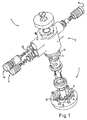
図1は、例示として、浄水装置1を上方から見た斜視図を示し、浄水装置1は、フィルタヘッド2と交換式フィルタキャンドル3とを備える。このフィルタヘッドは、複数のフィルタヘッド部品、すなわち、ハウジング7、流入口バルブ8、流出口バルブ9、並びに、安全バルブ及び/又は洗浄バルブ10、そしてまたコード化構造5も備える。相補的なコード化構造4は、フィルタキャンドルに連結されている。これらコード化構造4,5は、フィルタヘッド及びフィルタキャンドルの許容された組み合わせのみを可能とすることを確実にすることをもたらす。
FIG. 1 shows, as an example, a perspective view of a water purifier 1 as viewed from above, and the water purifier 1 includes a filter head 2 and a replaceable filter candle 3. The filter head also comprises a plurality of filter head components: a housing 7, an inlet valve 8, an outlet valve 9, as well as a safety valve and / or a
この目的を達成するため、コード化構造4が、フィルタキャンドル3の端面6上に、軸方向に形成されるような対策がとられる。好適な本実施形態では、このコード化構造4は、例示として、1つの歯状部を構成し、この歯状部は、フィルタヘッド部品11における相補的に対応する凹部5と係合する。問題となっているこのフィルタキャンドルは、フィルタキャンドル3に連結されるコード化構造4の構成要素が、フィルタヘッド部品11に連結されるコード化構造5の構成要素と適合する場合にのみ、フィルタヘッドに取り付けることが可能となる。
In order to achieve this object, measures are taken such that the coding structure 4 is formed axially on the end face 6 of the filter candle 3. In the preferred embodiment, this coding structure 4 constitutes, by way of example, a tooth, which engages a correspondingly corresponding recess 5 in the
本実施形態に加えて、上述の実施形態と比較して改良されうる実施形態も考えられる。この実施形態では、上述の実施形態と同様に、コード化構造4が、端面6に連結される構成要素上に軸方向に向けて形成される。この型の構成要素は、例えば、端面6上に配置され、フィルタキャンドルへの連結に対応するリング、ディスク等であり、これらは、この型のコード化構造、または、コード化構造の機能を実現するのに適している。 In addition to this embodiment, the embodiment which can be improved compared with the above-mentioned embodiment is also considered. In this embodiment, the coding structure 4 is formed on the component connected to the end face 6 in the axial direction as in the above-described embodiment. The components of this type are, for example, rings, discs, etc., which are arranged on the end face 6 and correspond to the connection to the filter candle, which realize this type of coding structure or the function of the coding structure Suitable for doing.
このようなフィルタキャンドルの構成要素とフィルタキャンドルとの間の連結としては、例えば、ねじ結合、接着剤結合、クリップ及び/又はスナップ式の結合等が可能である。 Such a connection between the filter candle component and the filter candle can be, for example, a screw connection, an adhesive connection, a clip and / or a snap-type connection.
しかしながら、このような中間構成要素はまた、原則として、フィルタヘッド、さらに、対応する機械的な連結と併せて、完全に利用可能とされうる。
さらに本質的な特徴として、フィルタキャンドル3をフィルタヘッド2に取り付けるために、コード化構造4,5と、固定構造12と、の間に仕切りが設けられている。本実施形態においては、固定構造12は、バヨネット式固定構造12にて形成されている。このバヨネット式固定構造12は、フィルタキャンドルがヘッド2に挿入されたときに、対応するハウジング7と連結される。これにより、フィルタキャンドル3が固定された状態となったときに、フィルタヘッドとフィルタキャンドルとが、適切な浄水装置1を形成する。
However, such intermediate components can also be made fully available in principle, in principle, in conjunction with a filter head and corresponding mechanical connection.
As a further essential feature, a partition is provided between the coding structures 4 and 5 and the fixing
2つのコード化構造4,5は、それゆえに、嵌め合い構造を形成し、複数の歯状部が設けられる場合、これら歯状部は、図示されたように、相互に特定の角度関係14を有し、例えば、図2においては、歯状部の間隔は180度である。図1〜図3に示すとおり、歯状部5は、フィルタキャンドル3から離れる方向を向く構造4を有しており、フィルタヘッド部品11に設けられた相補的な関係にある凹部5と嵌合する。しかしながら、上述した実施形態と比較して改良された図示しない実施形態においては、嵌合構造の歯状部15を、例えば、フィルタヘッド部品11上に形成し、相補関係にある対応する凹部に、フィルタキャンドル3に向かう方向に嵌めこむことが実現可能にされる。フィルタキャンドル13から離れる方向に向けて、及び、フィルタキャンドル3に向かう方向に向けて、異なる方向に方向付けられた歯状部の組み合わせ構造もまた可能であり、このような組み合わせ構造は、コード化の配列構造として可能な範囲を拡張する。
The two coding structures 4 and 5 thus form a mating structure and when a plurality of teeth are provided, these teeth have a specific angular relationship 14 with each other as shown. For example, in FIG. 2, the interval between the teeth is 180 degrees. As shown in FIGS. 1 to 3, the tooth-like portion 5 has a structure 4 that faces away from the filter candle 3, and engages with a recessed portion 5 in a complementary relationship provided in the
この点においては、例えば、個々の歯状部を放射方向にオフセットすることにより、また、複数の歯状部を互いに放射方向にオフセットすることにより、さらに追加することも可能である。しかしこの場合でも、歯状部は、フィルタキャンドル3の端面6に対して軸方向に向けられる。フィルタキャンドル3の端面6に対して軸方向を向くコード化構造4,5を用いることにより、軸方向を向いていない場合にはフィルタキャンドルの外側、または、フィルタキャンドルの首部上に放射状に配置されることが必要とされるコード化構造を免れうるので、例えば、より小型の設計が実現可能となる。 In this respect, it is possible to add further by, for example, offsetting individual tooth portions in the radial direction and offsetting the plurality of tooth portions in the radial direction. However, even in this case, the tooth-like portion is directed in the axial direction with respect to the end face 6 of the filter candle 3. By using the coding structures 4 and 5 oriented in the axial direction with respect to the end face 6 of the filter candle 3, they are arranged radially on the outside of the filter candle or on the neck of the filter candle when not oriented in the axial direction. For example, a smaller design can be realized.
この型の実施形態のさらなる利点として、より小型の、よりコンパクトな構造であることから、フィルタキャンドルをより簡単かつ迅速に挿入できることが見出されうる。加えて、具体的には、固定構造12とコード化構造4,5とが個別に構成されていることに起因して、例えば、Oリング17にて形成された、対応する未処理水流入封止部、の下流の領域である封止領域内にコード化構造を配置することも可能である。
As a further advantage of this type of embodiment, it can be found that the filter candle can be inserted more easily and quickly due to its smaller and more compact construction. In addition, specifically, the corresponding untreated water inflow seal formed by, for example, the O-
ここで、例えば、図2に一例として、2つの歯状部15,16により図示されたようなコード化の選択肢としてのさらなる拡張は、歯状部の長さ及び/又は大きさに関してだけでなく、歯状部の配置及び個数に関する異なる構成により生じる。上述の実施形態と比較して改良された実施形態では、フィルタ3の端面6上に配置されうる、3つ、4つ又は任意の好ましい数の歯状部を設けうる。図2においては、一例として、ここでは、1つの歯状部のみにて、角度セグメント18がここに装着される。しかしながら、他の実施形態では、歯状部の数をさらに多くすることもできる。
Here, for example, as an example in FIG. 2, further expansion as a coding option as illustrated by the two
さらに特に好ましいとされるのは、例えば、図3に図示されるバルブ本体9にて形成されるように、コード化構造4,5が、フィルタヘッド部品11のための作動要素として形成される場合である。図3に示すバルブ本体19は、図1に示すバルブ本体の実施形態とは異なり、つまり、回転式バルブ本体にて形成されている。これに対して、図1に示したバルブ本体は、例示として、タペット式バルブとして図示されている。
Further particularly preferred is when the coding structures 4, 5 are formed as actuating elements for the
図3においては、一例として、流入口バルブ8及び流出口バルブ9が、バルブ本体19上に形成された方式で図示されている。このバルブ本体19上におけるさらなる可能なバルブの配置が、安全バルブ10及び/又は洗浄バルブ10により示されており、安全バルブ10及び/又は洗浄バルブ10は、本実施形態では単一のバルブで実現されている。
In FIG. 3, as an example, the inlet valve 8 and the outlet valve 9 are illustrated in a manner formed on the
上記の流入口バルブは、未処理水の流入を制御する役割を果たし、流出口バルブは、ろ過水の流れを制御する役割を果たす。上記の安全バルブは、交換式のフィルタキャンドルが外される前に、浄水装置内部にかかる圧力を減少させる役割を果たす。圧力の減少は、好ましくは、この目的のために設けられた管(ここでは図示しない)を通して行われる。洗浄バルブ10は、同時に、フィルタヘッドに交換式フィルタが挿入された際に、その交換式フィルタを洗浄する役割を果たし、その結果、交換式フィルタ中に存在するあらゆる不純物は洗い流され、さらに、この流出口管を通して排出されうる。
The inlet valve serves to control the inflow of untreated water, and the outlet valve serves to control the flow of filtered water. The safety valve serves to reduce the pressure applied to the inside of the water purifier before the replaceable filter candle is removed. The pressure reduction is preferably done through a tube (not shown here) provided for this purpose. At the same time, the cleaning
安全バルブ10又は洗浄バルブ10を制御するために、バルブ本体19は、制御用カム21又は制御用突起20を備えうる。制御用カム21又は制御用突起20は、関連するバルブをそれぞれの作動時間に対応して作動させるために、また、フィルタヘッド2に対する交換式フィルタキャンドル3の相対位置を決めたりするために操作される。
In order to control the
図3では、これらに加えてバルブタペット22が示されているが、図1においてもこのようなバルブタペットが単純化のため番号22で示されている。図1に示される安全バルブ又は洗浄バルブ10の作動方法は、図3に示されるバルブ10に対応しており同じである。この実施形態では、上記のバルブは、流入口バルブ又は流出口バルブとは異なり、それゆえ、回転式バルブではなく、カム及び/又は突起にて操作されるタペット式バルブである。好ましいとされる作用に応じて、上記のタペット式バルブは、その作用を比較的短時間で実行するために、作動されるか又は操作されうる。
In addition to these, a
必要に応じて、バルブ本体19は、例えば、さらなるバルブ23を備えることも可能であり、バルブ23は、例えば、さらなる装置に対応する連結のため、例えば、バイパスバルブにて形成される。この型のさらなる装置は、例えば、第1の浄水装置のフィルタキャンドルが消耗したときに、選択的に第2の浄水装置に切り換えることができるように、選択的に第1の浄水装置と並列に連結されうる増設の浄水装置とすることが可能である。図3には、ここではバヨネット式固定具の形で示された固定構造12とは個別に設計されたコード化構造4,5が、追加的に明確に示される。
If desired, the
これに対して図4は、縦軸24回りに回転された浄水装置1の同じ構成要素の図を示している。図4は、特に、安全バルブ10又は洗浄バルブ10を作動させるための制御用突起20を明確に示している。
On the other hand, FIG. 4 has shown the figure of the same component of the water purifier 1 rotated around the vertical axis 24. FIG. 4 specifically shows the
図5もまた浄水装置をさらに示しているが、取り外さなければ、バルブ本体で覆われているさらなる構成要素を示すことを可能にするため、バルブ本体19を取り除いて示している。浄水装置1のさらなる構成要素は、設定装置25であり、設定装置25は、流入口バルブ8を通じて浄水装置1に供給される未処理水の流れのうち、少なくとも2つの流路26,27(図7)間の部分流比率を設定するものである。流路26は、本実施形態においては、交換式フィルタキャンドル3のろ過部を通じて導かれる。流路27は、流路26を通じて供給される浄水装置1のろ過水の流れを混合又は処理するために、いわゆるバイパス部又は混合部を通って導かれる。
FIG. 5 also shows the water purification device further, but with the
図6に示すように、設定装置25は、未処理水分配要素28、及び、図7に最もよく示される、相補的な部分流水路ガイド要素29を備える。本実施形態の場合、部分流水路ガイド要素29は、フィルタカードリッジ3に連結された要素として、2つの部分流部のための2つの流入口開口部35,36、ろ過部26及びバイパス部27を備える。
As shown in FIG. 6, the setting
未処理水分配要素28は、例示として、環状に形成されており、凹部30,31及びカバー32,33を有するセグメント状部材を備える。このセグメント状部材は、流入口バルブを通じて供給される未処理水の流れを制御するために、相互の相対的な角度位置により、2つの流路26,27を、程度の差はあるけれども閉鎖、又は、開放する。それゆえ、浄水装置1で処理される水質は、ろ過水の流れとバイパスの流れとの間の比率を用いて、例えば、この目的のために設けられた調整輪34を操作することにより、制御される。
The untreated
実施形態によっては、全ての混合設定において本質的に同じ大きさとなる全断面が2つの部分流の合計から形成されるか、又は、他の実施形態としては、混合設定に応じて大きさが異なる、変動する部分流の全断面が形成されるように、未処理水分配要素28及び部分流水路ガイド要素29を相互に関連させて形成し又は調整することができる。全断面が主に一定となる場合、浄水装置の内部の圧力についても全ての混合装置内で本質的に一定に維持され、その結果、可能な限り均一なろ過作用が、それゆえに、全ての設定範囲においてもたらされる。
In some embodiments, the entire cross-section, which is essentially the same size in all mixing settings, is formed from the sum of the two partial flows, or in other embodiments, the size varies depending on the mixing settings. The raw
1…浄水装置
2…フィルタヘッド
3…フィルタキャンドル
4…コード化構造
5…コード化構造
6…端面
7…ハウジング
8…バルブ
9…バルブ
10…バルブ
11…フィルタヘッド部品
12…固定構造
13…嵌合構造
14…角度関係
15…歯状部
16…歯状部
17…封止部
18…角度セグメント
19…バルブ本体
20…制御用突起
21…制御用カム
22…タペット
23…バイパスバルブ
24…軸
25…設定装置
26…流路
27…流路
28…未処理水分配要素
29…部分流水路ガイド要素
30…凹部
31…凹部
32…カバー
33…カバー
34…調整輪
35…開口部
36…開口部
DESCRIPTION OF SYMBOLS 1 ... Water purifier 2 ... Filter head 3 ... Filter candle 4 ... Coding structure 5 ... Coding structure 6 ... End surface 7 ... Housing 8 ... Valve 9 ...
Claims (14)
フィルタキャンドル部品を有する交換式フィルタキャンドル(3)と、
フィルタヘッド部品とフィルタキャンドル部品との間に形成される、規定の組み合わせ以外のフィルタヘッド部品とフィルタキャンドル部品との接続を妨げるための誤接続防止構造(4,5)と、
を備えた浄水装置(1)であって、
前記フィルタヘッド部品は、カム及び突起の少なくとも一方にて操作されるタペット式バルブ(10)を制御するための制御用カム(21)又は制御用突起(20)と、回転式バルブ(8,9)とを備える回転式バルブ本体(19)を備え、
前記誤接続防止構造(4)は、前記フィルタキャンドル(3)の端面(6)上、及び、前記フィルタヘッドと前記フィルタキャンドルとの間の中間要素である前記フィルタキャンドル(3)の端面(6)に連結された要素上の少なくとも一方に、軸方向に形成されており、
更に、前記誤接続防止構造(4,5)は、固定構造(12)とは別個に形成され、軸方向の嵌合構造(13)にて形成される
ことを特徴とする浄水装置(1)。 A filter head (2) having a filter head component (11);
A replaceable filter candle (3) having filter candle parts;
Ru is formed between the filter head part and the filter candle components, erroneous connection prevention structure for preventing the connection between the defined filter head part and the filter candle parts other than the combination of the (4,5),
A water purifier (1) comprising
The filter head component includes a control cam (21) or control protrusion (20) for controlling the tappet valve (10) operated by at least one of a cam and a protrusion, and a rotary valve (8, 9). A rotary valve body (19) comprising:
The erroneous connection prevention structure (4) is formed on the end face (6) of the filter candle (3) which is an intermediate element on the end face (6 ) of the filter candle (3) and between the filter head and the filter candle. at least one of the connected components of the), are formed in the axial direction,
Further, the water purification apparatus (1) is characterized in that the erroneous connection prevention structure (4, 5) is formed separately from the fixing structure (12) and is formed by an axial fitting structure (13). .
フィルタキャンドル部品を有する交換式フィルタキャンドル(3)と、
フィルタヘッド部品とフィルタキャンドル部品との間に形成される、規定の組み合わせ以外のフィルタヘッド部品とフィルタキャンドル部品との接続を妨げるための誤接続防止構造(4,5)と、
を備えた浄水装置(1)であって、
前記フィルタヘッド部品は、カム及び突起の少なくとも一方にて操作されるタペット式バルブ(10)を制御するための制御用カム(21)又は制御用突起(20)と、回転式バルブ(8,9)とを備える回転式バルブ本体(19)を備え、
前記誤接続防止構造(4)は、前記フィルタキャンドル(3)の端面(6)上、及び、前記フィルタヘッドと前記フィルタキャンドルとの間の中間要素である前記フィルタキャンドル(3)の端面(6)に連結された要素上の少なくとも一方に、軸方向に形成されており、
更に、前記誤接続防止構造(4,5)は、軸方向の嵌合構造(13)にて形成される
ことを特徴とする浄水装置(1)。 A filter head (2) having a filter head component (11);
A replaceable filter candle (3) having filter candle parts;
Ru is formed between the filter head part and the filter candle components, erroneous connection prevention structure for preventing the connection between the defined filter head part and the filter candle parts other than the combination of the (4,5),
A water purifier (1) comprising
The filter head component includes a control cam (21) or control protrusion (20) for controlling the tappet valve (10) operated by at least one of a cam and a protrusion, and a rotary valve (8, 9). A rotary valve body (19) comprising:
The erroneous connection prevention structure (4) is formed on the end face (6) of the filter candle (3) which is an intermediate element on the end face (6 ) of the filter candle (3) and between the filter head and the filter candle. at least one of the connected components of the), are formed in the axial direction,
Further, the water purification device (1) is characterized in that the erroneous connection prevention structure (4, 5) is formed by an axial fitting structure (13 ).
前記嵌合構造(13)は、相互に特定の角度関係(14)を有する歯状部(15,16)を備える
ことを特徴とする浄水装置。 The water purifier according to claim 1 or 2 ,
The said fitting structure (13) is provided with the tooth-like part (15, 16) which has a specific angular relationship (14) mutually. The water purifier characterized by the above-mentioned.
前記嵌合構造(13)の歯状部が、前記フィルタキャンドル(3)から離れる方向及び前記フィルタキャンドル(3)に向かう方向の方向の組み合わせをなすこと
ことを特徴とする浄水装置。 The water purifier according to claim 3 ,
The water purifier, wherein the tooth-shaped portion of the fitting structure (13) has a combination of a direction away from the filter candle (3) and a direction toward the filter candle (3).
前記歯状部(15,16)が、異なる長さ及び大きさの少なくとも一方によりもたらされる
ことを特徴とする浄水装置。 The water purifier according to claim 3 or claim 4 ,
The water purifier characterized in that the teeth (15, 16) are provided by at least one of different lengths and sizes.
多様な誤接続防止構造設計のために、異なる数の歯状部が設けられる
ことを特徴とする浄水装置。 It is a water purifier of any one of Claims 1-5 ,
A water purifier having a different number of teeth for various misconnection prevention structure designs.
多様な誤接続防止構造設計のために、異なる数の歯状部が特定の角度セグメント(18)に設けられる
ことを特徴とする浄水装置。 It is a water purifier of any one of Claims 1-6 ,
A water purifier characterized in that a different number of teeth are provided in a specific angle segment (18) for various misconnection prevention structure designs.
前記誤接続防止構造(4,5)は、前記フィルタヘッド部品(11)における前記回転式バルブ(8,9)、及び、前記タペット式バルブ(10)の少なくとも一つを開閉するための作動要素にて形成される
ことを特徴とする浄水装置。 It is a water purifier of any one of Claims 1-7 ,
The misconnection prevention structure (4, 5), wherein the rotary valve in the filter head part (11) (8, 9), and, actuating elements for opening and closing at least one of said tappet valve (10) A water purifier characterized by being formed by.
前記バルブ本体(19)は、少なくとも1つの流入口バルブ(8)及び少なくとも1つの流出口バルブ(9)の少なくとも一方を備える
ことを特徴とする浄水装置。 It is a water purifier of any one of Claims 1-8 ,
The said valve main body (19) is equipped with at least one of an at least 1 inflow port valve (8) and an at least 1 outflow port valve (9). The water purifier characterized by the above-mentioned.
前記バルブ本体(19)は、安全バルブ(10)及び洗浄バルブ(10)の少なくとも一方を備える
ことを特徴とする浄水装置。 It is a water purifier of any one of Claims 1-9 ,
The said valve main body (19) is provided with at least one of a safety valve (10) and a washing | cleaning valve (10). The water purifier characterized by the above-mentioned.
前記バルブ本体(19)は、安全バルブ(10)及び洗浄バルブ(10)の少なくとも一方に対する制御用カム(21)及び制御用突起(22)の少なくとも一方を備える
ことを特徴とする浄水装置。 It is a water purifier of any one of Claims 1-10 ,
The said valve main body (19) is provided with at least one of the control cam (21) and control protrusion (22) with respect to at least one of a safety valve (10) and a washing | cleaning valve (10). The water purifier characterized by the above-mentioned.
前記バルブ本体(19)は、バイパスバルブ(23)を備える
ことを特徴とする浄水装置。 It is a water purifier of any one of Claims 1-11 ,
The said valve main body (19) is provided with a bypass valve (23). The water purifier characterized by the above-mentioned.
ろ過部により処理された水と、前記ろ過部により処理されていない水と、を混合する混合装置と、
未処理水の少なくとも2つの流路(26,27)であって、前記ろ過部を通じて前記混合装置に導かれる流路(26)と、前記ろ過部を通らずに前記混合装置に導かれる流路(27)との間の部分流比率を設定する設定装置(25)と、
が設けられた
ことを特徴とする浄水装置。 It is a water purifier of any one of Claims 1-12,
A mixing device for mixing water treated by the filtration unit and water not treated by the filtration unit;
At least two flow paths (26, 27) of untreated water, a flow path (26) guided to the mixing device through the filtration unit, and a flow channel guided to the mixing device without passing through the filtration unit A setting device (25) for setting a partial flow ratio between (27) and
A water purifier characterized by that.
前記設定装置(25)が、対応する未処理水の流れの通過に影響を与える凹部(30,31)及びカバー(32,33)の少なくとも一方を有する未処理水分配要素(28)と、対応する未処理水の供給ラインに接続される開口部(35,36)を有する相補的な部分流水路ガイド要素(29)と、を備える
ことを特徴とする浄水装置。 It is a water purifier of Claim 13 , Comprising:
The setting device (25), and untreated water distribution element having at least one recess that affect the passage of the flow of the corresponding untreated water (30, 31) and the cover (32, 33) (28), corresponding the complementary parts water passage guide element having an opening (35, 36) connected to the supply line of the untreated water (29), water purification apparatus comprising: a.
Applications Claiming Priority (3)
| Application Number | Priority Date | Filing Date | Title |
|---|---|---|---|
| DE102006044744.1 | 2006-09-20 | ||
| DE102006044744.1A DE102006044744C5 (en) | 2006-09-20 | 2006-09-20 | Water filter device with encryption structure |
| PCT/EP2007/007742 WO2008034523A1 (en) | 2006-09-20 | 2007-09-05 | Water filter device having encoding structure |
Publications (3)
| Publication Number | Publication Date |
|---|---|
| JP2010504192A JP2010504192A (en) | 2010-02-12 |
| JP2010504192A5 JP2010504192A5 (en) | 2010-10-07 |
| JP5290180B2 true JP5290180B2 (en) | 2013-09-18 |
Family
ID=38961892
Family Applications (1)
| Application Number | Title | Priority Date | Filing Date |
|---|---|---|---|
| JP2009528615A Expired - Fee Related JP5290180B2 (en) | 2006-09-20 | 2007-09-05 | Water purifier with coded structure |
Country Status (11)
| Country | Link |
|---|---|
| US (2) | US8394269B2 (en) |
| EP (2) | EP2749336B1 (en) |
| JP (1) | JP5290180B2 (en) |
| KR (2) | KR101766608B1 (en) |
| CN (1) | CN101553295B (en) |
| DE (1) | DE102006044744C5 (en) |
| DK (1) | DK2063973T3 (en) |
| ES (1) | ES2476246T3 (en) |
| PL (1) | PL2063973T3 (en) |
| RU (1) | RU2434665C2 (en) |
| WO (1) | WO2008034523A1 (en) |
Families Citing this family (30)
| Publication number | Priority date | Publication date | Assignee | Title |
|---|---|---|---|---|
| EP2298431B1 (en) * | 2005-07-20 | 2014-01-01 | 3M Innovative Properties Co. | Fluid filtration system |
| DE102006044744C5 (en) | 2006-09-20 | 2021-04-01 | Aquis Wasser-Luftsysteme GmbH Lindau, Zweigniederlassung Rebstein | Water filter device with encryption structure |
| DE102008029533A1 (en) * | 2008-06-21 | 2009-12-24 | Krones Ag | Device for handling, in particular filtration of liquids |
| US9901852B2 (en) | 2008-08-08 | 2018-02-27 | Kx Technologies Llc | Push filter with floating key lock |
| US11426685B2 (en) | 2008-08-08 | 2022-08-30 | Kx Technologies Llc | Push filter with floating key lock |
| US9233322B1 (en) | 2008-08-08 | 2016-01-12 | Kx Technologies Llc | Push filter with floating key lock |
| US10040703B2 (en) | 2008-08-08 | 2018-08-07 | Kx Technologies Llc | Reverse osmosis push filter with floating key lock |
| US8137551B1 (en) | 2008-08-08 | 2012-03-20 | Kx Technologies, Llc | Push filter with floating key lock |
| BRPI0913555B1 (en) * | 2008-09-16 | 2019-06-25 | 3M Innovative Properties Company | FILTER CARTRIDGE AND FILTER CARTRIDGE INSTALLATION AND REMOVAL METHOD |
| DE102010005390A1 (en) * | 2010-01-22 | 2011-07-28 | MAHLE International GmbH, 70376 | filtering device |
| US9695579B2 (en) | 2011-03-15 | 2017-07-04 | Sloan Valve Company | Automatic faucets |
| CN105804166B (en) | 2011-03-15 | 2019-03-26 | 仕龙阀门公司 | Automatic faucet |
| MX359527B (en) | 2011-06-21 | 2018-10-01 | Kinetico Incorporated | Water treatment system. |
| KR101311654B1 (en) * | 2011-11-02 | 2013-09-25 | 정휘동 | Water purifying filter assembly |
| US9764263B2 (en) * | 2012-03-01 | 2017-09-19 | Caterpillar Inc. | Filter element |
| JP2017127841A (en) * | 2016-01-22 | 2017-07-27 | 日本濾過器株式会社 | Filter and valve device |
| US10905989B2 (en) * | 2018-05-16 | 2021-02-02 | Haier Us Appliance Solutions, Inc. | Electromagnet interface for a water filter assembly |
| US10913020B2 (en) * | 2018-05-16 | 2021-02-09 | Haier Us Appliance Solutions, Inc. | Magnetic interface for a water filter assembly |
| US11273397B2 (en) | 2018-09-13 | 2022-03-15 | Electrolux Home Products, Inc. | Filter base for electronic connection to mating filter housing assembly |
| USD948660S1 (en) | 2019-11-18 | 2022-04-12 | Electrolux Home Products, Inc. | Filter cartridge |
| USD946701S1 (en) | 2019-11-18 | 2022-03-22 | Electrolux Home Products, Inc. | Filter cartridge |
| USD946702S1 (en) | 2019-11-18 | 2022-03-22 | Electrolux Home Products, Inc. | Filter cartridge |
| USD946699S1 (en) | 2019-11-18 | 2022-03-22 | Electrolux Home Products, Inc. | Filter cartridge |
| US11413560B2 (en) | 2019-11-18 | 2022-08-16 | Electrolux Home Products, Inc. | Push filter with floating key lock |
| USD969270S1 (en) | 2019-11-18 | 2022-11-08 | Electrolux Home Products, Inc. | Filter cartridge |
| USD948659S1 (en) | 2019-11-18 | 2022-04-12 | Electrolux Home Products, Inc. | Filter cartridge |
| USD946703S1 (en) | 2019-11-18 | 2022-03-22 | Electrolux Home Products, Inc. | Filter cartridge |
| USD946700S1 (en) | 2019-11-18 | 2022-03-22 | Electrolux Home Products, Inc. | Filter cartridge |
| CA3105784A1 (en) * | 2020-03-06 | 2021-09-06 | Global Industrial Distribution Inc. | Bottle filler fountain |
| US11311827B1 (en) | 2021-12-31 | 2022-04-26 | ERD Paris, LLC | Water filter system head with interchangeable inlet and outlet connections |
Family Cites Families (34)
| Publication number | Priority date | Publication date | Assignee | Title |
|---|---|---|---|---|
| US3334754A (en) * | 1964-11-23 | 1967-08-08 | Marvel Eng Co | Filter head structure |
| US4515692A (en) * | 1983-05-06 | 1985-05-07 | Water Soft, Inc. | Water filter |
| US5035797A (en) * | 1990-02-14 | 1991-07-30 | Stanadyne Automotive Corp. | Key system for filter assembly |
| US5174337A (en) * | 1990-10-31 | 1992-12-29 | Erie Manufacturing Company | Water conditioner rotary valve |
| US5186829A (en) | 1991-08-16 | 1993-02-16 | Stanadyne Automotive Corp. | Fuel filter key system |
| JPH06178972A (en) * | 1992-12-14 | 1994-06-28 | Takuma Co Ltd | Water purifier |
| US5336406A (en) * | 1993-01-26 | 1994-08-09 | Elkay Manufacturing Company | Replaceable filter cartridge and head assembly with safety shut-off valve |
| JP3585586B2 (en) * | 1995-07-28 | 2004-11-04 | 松下電器産業株式会社 | Mixing faucet with water purifier |
| JP2715371B2 (en) * | 1995-12-28 | 1998-02-18 | クリタック株式会社 | Water purification equipment |
| US5693219A (en) * | 1996-01-31 | 1997-12-02 | Beauchamp; William J. | Apparatus for backwashing a water filter |
| US5826854A (en) * | 1996-06-07 | 1998-10-27 | Amana Refrigeration, Inc. | Fluid routing system |
| US5914037A (en) * | 1997-11-24 | 1999-06-22 | Yen; Chiu-Sen | Filter device for a water filter |
| CN2375824Y (en) * | 1999-06-03 | 2000-04-26 | 谭玉申 | Cam-washing valve |
| DE19958648A1 (en) * | 1999-12-06 | 2001-06-07 | Brita Gmbh | Water filter device |
| US6949189B2 (en) * | 2000-04-20 | 2005-09-27 | Cuno Incorporated | Keyed filter assembly |
| US6458269B1 (en) * | 2000-04-20 | 2002-10-01 | Cuno Incorporated | Keyed filter assembly |
| US7407148B2 (en) * | 2000-04-20 | 2008-08-05 | 3M Innovative Properties Company | Rotary valve assembly for fluid filtration system |
| ATE452692T1 (en) * | 2000-05-12 | 2010-01-15 | Pall Corp | FILTRATION SYSTEMS |
| EP1286748B1 (en) * | 2000-05-12 | 2006-01-25 | Pall Corporation | Filters |
| KR100975997B1 (en) * | 2000-08-11 | 2010-08-17 | 로저 피. 리이드 | Keyed system for connection of filter cartridge to filter holder |
| FR2818917B1 (en) * | 2000-12-28 | 2003-10-03 | Dan Vasilescu | FILTER FOR THE PARTICULATE DEPOLLUTION OF FLUIDS |
| US20020166805A1 (en) * | 2001-03-21 | 2002-11-14 | Minns Gian D. | Filter assembly and method of manufacture |
| CN2520931Y (en) * | 2002-01-14 | 2002-11-20 | 符福煜 | Domestic full automatic back flushing water treatment device |
| DE10231096B9 (en) * | 2002-07-10 | 2006-11-09 | Brita Gmbh | Filter device and inner container for a filter device |
| US6923910B2 (en) * | 2003-01-07 | 2005-08-02 | Cuno Incorporated | Filter cartridge having bypass feature |
| US20050023206A1 (en) * | 2003-07-29 | 2005-02-03 | Karl Fritze | Water filter adapter with locking feature |
| DE10353424B4 (en) * | 2003-11-15 | 2012-12-13 | Mahle Filtersysteme Gmbh | Liquid filter, in particular oil filter for a motor vehicle, and associated ring filter element |
| WO2006016924A1 (en) * | 2004-07-12 | 2006-02-16 | Mykrolis Corporation | Mass or energy transfer cartridge |
| US7326342B2 (en) * | 2004-09-13 | 2008-02-05 | Baldwin Filters, Inc. | Fuel filter cartridge and keyed end cap |
| CN2741960Y (en) * | 2004-10-28 | 2005-11-23 | 厦门建霖卫浴工业有限公司 | Water purifier |
| DE102005007022A1 (en) * | 2005-02-15 | 2006-10-26 | Mann + Hummel Gmbh | filtering device |
| WO2006091557A2 (en) * | 2005-02-22 | 2006-08-31 | Baldwin Filters, Inc. | Filter apparatus |
| KR100712266B1 (en) * | 2005-03-24 | 2007-05-17 | 주식회사 피코그램 | purification filter of using connector and water purification ddevice |
| DE102006044744C5 (en) | 2006-09-20 | 2021-04-01 | Aquis Wasser-Luftsysteme GmbH Lindau, Zweigniederlassung Rebstein | Water filter device with encryption structure |
-
2006
- 2006-09-20 DE DE102006044744.1A patent/DE102006044744C5/en active Active
-
2007
- 2007-09-05 DK DK07818054.4T patent/DK2063973T3/en active
- 2007-09-05 KR KR1020167007514A patent/KR101766608B1/en active IP Right Grant
- 2007-09-05 CN CN2007800429443A patent/CN101553295B/en active Active
- 2007-09-05 KR KR1020097007910A patent/KR101638192B1/en active IP Right Grant
- 2007-09-05 WO PCT/EP2007/007742 patent/WO2008034523A1/en active Application Filing
- 2007-09-05 ES ES07818054.4T patent/ES2476246T3/en active Active
- 2007-09-05 PL PL07818054T patent/PL2063973T3/en unknown
- 2007-09-05 EP EP14000356.7A patent/EP2749336B1/en active Active
- 2007-09-05 JP JP2009528615A patent/JP5290180B2/en not_active Expired - Fee Related
- 2007-09-05 EP EP07818054.4A patent/EP2063973B1/en not_active Revoked
- 2007-09-05 US US12/311,108 patent/US8394269B2/en active Active
- 2007-09-05 RU RU2009114720/05A patent/RU2434665C2/en active
-
2013
- 2013-03-12 US US13/815,586 patent/US9409794B2/en active Active
Also Published As
| Publication number | Publication date |
|---|---|
| US9409794B2 (en) | 2016-08-09 |
| EP2063973B1 (en) | 2014-04-02 |
| KR20160038069A (en) | 2016-04-06 |
| WO2008034523A1 (en) | 2008-03-27 |
| JP2010504192A (en) | 2010-02-12 |
| EP2063973A1 (en) | 2009-06-03 |
| US8394269B2 (en) | 2013-03-12 |
| ES2476246T3 (en) | 2014-07-14 |
| CN101553295B (en) | 2013-04-24 |
| DK2063973T3 (en) | 2014-06-30 |
| EP2749336B1 (en) | 2019-10-09 |
| US20130220909A1 (en) | 2013-08-29 |
| RU2009114720A (en) | 2010-10-27 |
| KR101638192B1 (en) | 2016-07-08 |
| KR20090082357A (en) | 2009-07-30 |
| PL2063973T3 (en) | 2015-01-30 |
| DE102006044744A1 (en) | 2008-03-27 |
| RU2434665C2 (en) | 2011-11-27 |
| DE102006044744B4 (en) | 2017-11-02 |
| DE102006044744C5 (en) | 2021-04-01 |
| CN101553295A (en) | 2009-10-07 |
| US20100018912A1 (en) | 2010-01-28 |
| EP2749336A1 (en) | 2014-07-02 |
| KR101766608B1 (en) | 2017-08-08 |
Similar Documents
| Publication | Publication Date | Title |
|---|---|---|
| JP5290180B2 (en) | Water purifier with coded structure | |
| JP2009532199A (en) | Clean water filter cartridge system with an integrated mixing valve system in the candle and an adjustment device in the head | |
| JP4648971B2 (en) | Water purifier | |
| JP5374160B2 (en) | Bypass valve with integrated flow sensor for water treatment systems | |
| KR100870572B1 (en) | Water Purification Filter Assembly using a swivel type connector | |
| US10359122B2 (en) | Control valve for a water softener | |
| KR20170050576A (en) | Flow path switching valve and Water treatment apparatus having the same | |
| WO2009025413A1 (en) | Water purifier filter having a filter washing function | |
| JP2008104902A (en) | Container for water purifier | |
| JP2584046Y2 (en) | Hot water mixing faucet with water purifier installed in the sink tank | |
| JP3310575B2 (en) | Single lever faucet | |
| KR200420880Y1 (en) | Water purifier having washing pipe | |
| JP3779566B2 (en) | Water purifier and its installation method | |
| JP4689520B2 (en) | Cylinder type valve device | |
| JP3707828B2 (en) | Water purification system | |
| JP4085727B2 (en) | Water purifier | |
| JPH1015540A (en) | Water purifier | |
| JPH0717893Y2 (en) | Clean water / backwash switching valve device for water filter | |
| JP3032805U (en) | Water tap for under sink type water purifier | |
| JP3745646B2 (en) | Tap water purification cartridge | |
| KR20230146807A (en) | Faucet | |
| JP2007222818A (en) | Bypassing switch unit of water purifier | |
| JPH07308665A (en) | Water purifier | |
| JP4451796B2 (en) | Purification cartridge | |
| JP2004169757A (en) | Switching cock |
Legal Events
| Date | Code | Title | Description |
|---|---|---|---|
| A521 | Request for written amendment filed |
Free format text: JAPANESE INTERMEDIATE CODE: A523 Effective date: 20100816 |
|
| A621 | Written request for application examination |
Free format text: JAPANESE INTERMEDIATE CODE: A621 Effective date: 20100816 |
|
| A977 | Report on retrieval |
Free format text: JAPANESE INTERMEDIATE CODE: A971007 Effective date: 20110805 |
|
| A131 | Notification of reasons for refusal |
Free format text: JAPANESE INTERMEDIATE CODE: A131 Effective date: 20110823 |
|
| A601 | Written request for extension of time |
Free format text: JAPANESE INTERMEDIATE CODE: A601 Effective date: 20111124 |
|
| A602 | Written permission of extension of time |
Free format text: JAPANESE INTERMEDIATE CODE: A602 Effective date: 20111201 |
|
| A601 | Written request for extension of time |
Free format text: JAPANESE INTERMEDIATE CODE: A601 Effective date: 20111221 |
|
| A602 | Written permission of extension of time |
Free format text: JAPANESE INTERMEDIATE CODE: A602 Effective date: 20120104 |
|
| A601 | Written request for extension of time |
Free format text: JAPANESE INTERMEDIATE CODE: A601 Effective date: 20120123 |
|
| A602 | Written permission of extension of time |
Free format text: JAPANESE INTERMEDIATE CODE: A602 Effective date: 20120130 |
|
| A521 | Request for written amendment filed |
Free format text: JAPANESE INTERMEDIATE CODE: A523 Effective date: 20120223 |
|
| A131 | Notification of reasons for refusal |
Free format text: JAPANESE INTERMEDIATE CODE: A131 Effective date: 20120807 |
|
| TRDD | Decision of grant or rejection written | ||
| A01 | Written decision to grant a patent or to grant a registration (utility model) |
Free format text: JAPANESE INTERMEDIATE CODE: A01 Effective date: 20130507 |
|
| A61 | First payment of annual fees (during grant procedure) |
Free format text: JAPANESE INTERMEDIATE CODE: A61 Effective date: 20130605 |
|
| R150 | Certificate of patent or registration of utility model |
Ref document number: 5290180 Country of ref document: JP Free format text: JAPANESE INTERMEDIATE CODE: R150 |
|
| R250 | Receipt of annual fees |
Free format text: JAPANESE INTERMEDIATE CODE: R250 |
|
| R250 | Receipt of annual fees |
Free format text: JAPANESE INTERMEDIATE CODE: R250 |
|
| R250 | Receipt of annual fees |
Free format text: JAPANESE INTERMEDIATE CODE: R250 |
|
| R250 | Receipt of annual fees |
Free format text: JAPANESE INTERMEDIATE CODE: R250 |
|
| R250 | Receipt of annual fees |
Free format text: JAPANESE INTERMEDIATE CODE: R250 |
|
| R250 | Receipt of annual fees |
Free format text: JAPANESE INTERMEDIATE CODE: R250 |
|
| R250 | Receipt of annual fees |
Free format text: JAPANESE INTERMEDIATE CODE: R250 |
|
| LAPS | Cancellation because of no payment of annual fees |