JP5289997B2 - A lesion model placed in the lumen of the duct - Google Patents
A lesion model placed in the lumen of the duct Download PDFInfo
- Publication number
- JP5289997B2 JP5289997B2 JP2009034659A JP2009034659A JP5289997B2 JP 5289997 B2 JP5289997 B2 JP 5289997B2 JP 2009034659 A JP2009034659 A JP 2009034659A JP 2009034659 A JP2009034659 A JP 2009034659A JP 5289997 B2 JP5289997 B2 JP 5289997B2
- Authority
- JP
- Japan
- Prior art keywords
- lesion model
- lesion
- lumen
- hole
- model
- Prior art date
- Legal status (The legal status is an assumption and is not a legal conclusion. Google has not performed a legal analysis and makes no representation as to the accuracy of the status listed.)
- Active
Links
Images


Landscapes
- Instructional Devices (AREA)
- Media Introduction/Drainage Providing Device (AREA)
Description
本発明は、管の内腔部に配置される病変モデルに関する。 The present invention relates to a lesion model placed in the lumen of a tube.
経皮的冠動脈形成術の一つとして、例えば、PTCA術(Percutaneous Transluminal Coronary Angioplasty:経皮的冠状動脈形成術)が知られている。 As one of the percutaneous coronary angioplasty, for example, PTCA (Percutaneous Transluminal Coronary Angioplasty) is known.
このPTCA術では、経大腿動脈法を適用した場合、次のような手技を経て、血管内の血流を回復させる。すなわち、I.まず、大腿動脈にシースカテーテルを挿入、次いで、これにガイドカテーテル用ガイドワイヤを挿入し、その先端を冠動脈入口付近まで進めた状態で、ガイドカテーテル用ガイドワイヤに沿わせてガイドカテーテルを進め、その先端を冠動脈口に位置させる。II.次に、ガイドカテーテル用ガイドワイヤを抜去し、バルーンカテーテル用ガイドワイヤをガイドカテーテル内に挿入して、ガイドカテーテルの先端からバルーンカテーテル用ガイドワイヤを突出させ、さらに冠動脈に生じている狭窄部位(病変部位)を越えた位置にまで進める。III.次に、バルーンカテーテル用ガイドワイヤを介してバルーンカテーテルを狭窄部位まで進め、バルーン部を狭窄部位に位置させた後、バルーンを膨張することにより狭窄部位すなわち血管壁を押し広げ、血液の通路を再形成して血流を回復させる。 In this PTCA technique, when the transfemoral artery method is applied, the blood flow in the blood vessel is recovered through the following procedure. That is, I.I. First, insert a sheath catheter into the femoral artery, then insert a guide catheter guide wire into the femoral artery, and advance the guide catheter along the guide catheter guide wire with its tip advanced to the vicinity of the coronary artery entrance. The tip is located at the coronary ostium. II. Next, the guide wire for the guide catheter is removed, the guide wire for the balloon catheter is inserted into the guide catheter, the guide wire for the balloon catheter is projected from the distal end of the guide catheter, and a stenotic site (lesion) occurring in the coronary artery Advance to a position beyond (part). III. Next, the balloon catheter is advanced to the stenosis site via the balloon catheter guide wire, and after the balloon portion is positioned at the stenosis site, the balloon is inflated to widen the stenosis site, that is, the blood vessel wall and re-open the blood passage. Form and restore blood flow.
以上のように、バルーンカテーテルを狭窄部位に位置させるには、複雑な工程を有し、術者には、極めて高度な技術が求められる。 As described above, in order to position the balloon catheter at the stenosis site, there are complicated steps, and the operator is required to have a very advanced technique.
そのため、近年、患者に対する手術の他に、術者の技術を向上さるための訓練に用いる生体モデルの開発が求められている。 Therefore, in recent years, in addition to surgery for patients, development of a biological model used for training for improving an operator's technique is required.
かかる生体モデルとして、血管やリンパ管のような管をモデルとした管モデルの製造方法が、例えば、特許文献1で提案されている。
As such a living body model, for example,
すなわち、特許文献1では、まず、CTスキャナやMRIスキャナ等の画像診断装置により得られた被検体の断層像データに基づき、この被検体の腔所領域を抽出してこの腔所領域に相当する内腔モデルを積層造形する。次に、この内腔モデルの周囲を立体モデル成形材料で囲繞した状態で立体モデル成形材料を硬化させた後、内腔モデルを除去することにより管モデル(立体モデル)を形成する。
That is, in
かかる構成の立体モデルでは、立体モデル成形材料としてシリコーンゴムやポリウレタンエラストマー等が用いられ、管モデルは、血管やリンパ管の物理的性質に近似させて形成される。そして、この立体モデルは、内腔モデルを囲繞するようにして形成されるため、病変部位である狭窄部位も前記管と一体的に形成され、管と同様の物理的性質を示すこととなる。しかしながら、例えば、血管に形成される狭窄部位は、主としてコレステロールが沈着したプラーク(沈着物)で構成されているため、その物理的性質は、血管とは大きく異なる。 In the three-dimensional model having such a configuration, silicone rubber, polyurethane elastomer, or the like is used as the three-dimensional model molding material, and the tube model is formed by approximating the physical properties of blood vessels and lymph vessels. Since this three-dimensional model is formed so as to surround the lumen model, a stenosis site, which is a lesion site, is also formed integrally with the tube and exhibits the same physical properties as the tube. However, for example, a stenosis site formed in a blood vessel is mainly composed of plaques (deposits) on which cholesterol is deposited, so that its physical properties are significantly different from those of blood vessels.
そのため、特許文献1に記載の立体モデルでは、狭窄部位に生じた実際のプラークの物理的性質に対応した訓練を実施できず、バルーンを狭窄部位で膨らませた後のプラークの状態が確認できないため、血液の流路の再構築がどのようになされているかを知ることができないという問題がある。
Therefore, in the three-dimensional model described in
さらに、立体モデルは、一人の被検体の断層像データに基づいて製造されているため、この被検体が健常者であった場合には、患者を対象とした訓練、すなわち、狭窄部位に対してバルーンを膨らませる訓練を実施することができない。また、たとえ、被検体が患者であったとしても、その患者が有する狭窄部位の位置または形状に対する訓練しかできず、様々な、位置および形状で生じる狭窄部位に対応した訓練を実施することができない。 Furthermore, since the three-dimensional model is manufactured based on the tomographic image data of one subject, if this subject is a healthy person, training for the patient, that is, for the stenosis site, Training to inflate the balloon is not possible. Moreover, even if the subject is a patient, only the training for the position or shape of the stenosis site that the patient has can be performed, and training corresponding to the stenosis site that occurs in various positions and shapes cannot be performed. .
本発明の目的は、血管等の内腔部を備える管に病変モデルを配置した状態で、この病変モデルを用いて術者の技術向上を目的とする訓練を行う際に、病変モデルを実際の病変部位の物理的性質に近似して訓練することができ、さらに前記内腔部において、その任意の位置に任意の形状で配置することができる病変モデルを提供することにある。 The object of the present invention is to use a lesion model in a tube having a lumen such as a blood vessel, and when performing training for improving the skill of the operator using this lesion model, An object of the present invention is to provide a lesion model that can be trained to approximate the physical properties of a lesion site and can be arranged in any shape at any position in the lumen.
このような目的は、下記(1)〜(9)の本発明により達成される。
(1) 内腔部を有する管の前記内腔部に配置され、前記内腔部に配置した際に前記内腔部を狭窄または閉塞する形状をなす病変モデルであって、
当該病変モデルは、主としてシリコーン粘土、樹脂粘土および油粘土のうちの少なくとも1種で構成される塑性変形可能な材料で構成されており、
当該病変モデルを前記内腔部に配置し、流路を確保するために拡張する訓練を行ったとき、前記拡張により拡張前の形状に戻らない程度に塑性変形するものであることを特徴とする病変モデル。
Such an object is achieved by the present inventions (1) to ( 9 ) below.
(1) A lesion model that is disposed in the lumen portion of a tube having a lumen portion, and has a shape that narrows or closes the lumen portion when disposed in the lumen portion,
The lesion model is composed of a plastically deformable material mainly composed of at least one of silicone clay, resin clay and oil clay .
When the lesion model is placed in the lumen part and subjected to training for expansion to ensure a flow path, it is plastically deformed to the extent that it does not return to the shape before expansion due to the expansion. Lesion model.
(2) 前記管よりも、その弾性率が小さい上記(1)に記載の病変モデル。 (2) The lesion model according to (1), which has a smaller elastic modulus than the tube .
(3) 軸方向に貫通する貫通孔を有し、前記内腔部に配置した際に、前記貫通孔の外周部により前記内腔部を狭窄する上記(1)または(2)に記載の病変モデル。 ( 3 ) The lesion according to the above (1) or (2) , which has a through-hole penetrating in the axial direction and narrows the lumen by the outer peripheral portion of the through-hole when arranged in the lumen. model.
(4) 前記貫通孔は、その一端部または両端部に前記貫通孔の孔径がその内部側から端部側に向かって漸増するテーパ部を備える上記(3)に記載の病変モデル。 ( 4 ) The lesion model according to ( 3 ), wherein the through hole includes a tapered portion in which the diameter of the through hole gradually increases from the inner side toward the end side at one end portion or both end portions thereof.
(5) 軸方向に連続する切れ目または孔を有し、前記内腔部に配置した際に、前記切れ目または前記孔の内面同士が密着することにより、前記内腔部を閉塞する上記または(2)に記載の病変モデル。 ( 5 ) The above or (2 ) which has an axially continuous cut or hole and closes the lumen when the inner surfaces of the cut or the hole are in close contact with each other when arranged in the lumen. ) Lesion model described in.
(6) 前記切れ目または孔の一端または両端に、前記切れ目または孔から連続する貫通孔を有し、該貫通孔は、その孔径がその内部側から端部側に向かって漸増するテーパ部を備える上記(5)に記載の病変モデル。 ( 6 ) One end or both ends of the cut or hole have a through hole continuous from the cut or hole, and the through hole has a tapered portion whose diameter gradually increases from the inner side toward the end side. The lesion model according to ( 5 ) above.
(7) 前記内腔部に圧縮された状態で挿入される上記(1)ないし(6)のいずれかに記載の病変モデル。 ( 7 ) The lesion model according to any one of (1) to ( 6 ), wherein the lesion model is inserted into the lumen in a compressed state.
(8) 塑性変形可能な材料をワイヤおよび押し子が挿入された外筒に充填して成形したものである上記(1)ないし(7)のいずれかに記載の病変モデル。 ( 8 ) The lesion model according to any one of (1) to ( 7 ), wherein a plastically deformable material is filled in an outer cylinder into which a wire and a pusher are inserted.
(9) 1種または2種以上の医療器具を、前記管内を挿通させて前記病変モデルに到達させた後、前記病変モデルを拡張させる訓練に用いられる上記(1)ないし(8)のいずれかに記載の病変モデル。 ( 9 ) Any one of the above (1) to ( 8 ) used for training for extending the lesion model after one or more medical devices are inserted through the tube to reach the lesion model The lesion model described in 1.
本発明によれば、血管等の内腔部を有する管を用いた立体モデルにおいて、病変部位の物理的性質に近似した病変モデルを、その任意の位置に任意の形状で配置することができる。そのため、この病変モデルを備える立体モデルを用いて、さまざまな患者の病態に対応した訓練を実施できることから、術者は、患者に施す手術以外の場で、より高度な技術を習得することができる。 According to the present invention, in a three-dimensional model using a tube having a lumen such as a blood vessel, a lesion model that approximates the physical properties of a lesion site can be arranged in an arbitrary shape at an arbitrary position. For this reason, since a three-dimensional model including this lesion model can be used to perform training corresponding to various patient pathologies, the surgeon can acquire more advanced techniques in a place other than the surgery performed on the patient. .
以下、本発明の病変モデルを添付図面に示す好適な実施形態に基づいて詳細に説明する。 Hereinafter, the lesion model of the present invention will be described in detail based on a preferred embodiment shown in the accompanying drawings.
本発明の病変モデルは、内腔部を備える管の該内腔部に配置され、前記内腔部に配置した際に前記内腔部を狭窄または閉塞する形状をなす病変モデルであり、当該病変モデルは、塑性変形可能な材料で構成されており、前記病変モデルを前記内腔部に配置し、流路を確保するために拡張する訓練を行ったとき、前記拡張により拡張前の形状に戻らない程度に塑性変形するものである。 The lesion model of the present invention is a lesion model that is disposed in the lumen portion of a tube having a lumen portion, and has a shape that narrows or closes the lumen portion when disposed in the lumen portion. The model is made of a plastically deformable material, and when the lesion model is placed in the lumen and is trained to expand to secure a flow path, the expansion returns to the shape before expansion. It will be plastically deformed to a certain extent.
この病変モデルは、例えば、血管(動脈、静脈)、リンパ管、胆管、尿管、卵管等の内腔部を備えるヒトの生体の各種管を再現して人工的に製造された立体モデル(管モデル)に配置され、かかる立体モデルを用いて、病変モデルにバルーンカテーテル等の医療器具を到達させ、その後、病変モデルを拡張することにより流路を確保したり、拡張した病変モデルにステントを留置するための訓練等が実施される。以下では、動脈の形状に対応して形成された立体モデルに、本発明の病変モデルを配置する場合を一例に説明する。 This lesion model is, for example, a three-dimensional model (manufactured artificially by reproducing various pipes of a human body having lumens such as blood vessels (arteries, veins), lymphatic vessels, bile ducts, ureters, oviducts, etc.) Using this three-dimensional model, a medical device such as a balloon catheter is made to reach the lesion model, and then the lesion model is expanded to secure a flow path, or a stent is attached to the expanded lesion model. Training for detention is conducted. Below, the case where the lesion model of this invention is arrange | positioned to the solid model formed corresponding to the shape of the artery is demonstrated to an example.
ヒトの全身における動脈(心臓を含む)は、図1の模式図に示すような形状をなしている。この動脈の形状に対応した立体モデルは、例えば、特許第3613568号公報の記載に基づいて、次のようにして製造される。 Arteries (including the heart) in the whole human body have a shape as shown in the schematic diagram of FIG. A three-dimensional model corresponding to the shape of the artery is manufactured as follows based on, for example, the description of Japanese Patent No. 3613568.
まず、動脈が備える腔部(血液の流路)の断層像データをCTスキャナ、MRIスキャナのような画像診断装置を用いて得た後、この動脈の内腔部に対応する断層像データに基づいて動脈の内腔部の形状をなす内腔モデルを積層造形する。 First, tomographic image data of a cavity (blood flow path) provided in an artery is obtained using an image diagnostic apparatus such as a CT scanner or an MRI scanner, and then based on the tomographic image data corresponding to the lumen of the artery. Then, a lumen model that forms the shape of the lumen of the artery is layered.
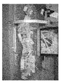
次に、内腔モデルの周囲を立体モデル成形材料で囲繞した状態で立体モデル成形材料を硬化させた後、内腔モデルを除去することにより、図2の全体写真に示すような、動脈の形状に対応した動脈モデル(立体モデル)が形成される。 Next, after hardening the three-dimensional model molding material in a state in which the periphery of the lumen model is surrounded by the three-dimensional model molding material, the lumen model is removed, and the shape of the artery as shown in the whole photograph of FIG. An arterial model (three-dimensional model) corresponding to is formed.
上記のような動脈モデルが備える各部の動脈(モデル)、例えば、冠動脈、脳動脈、頸動脈、腎動脈、上腕動脈等の任意の位置に、本発明の病変モデルを配置することにより、バルーンカテーテル等の医療器具を病変モデル(狭窄モデル)に位置させた後、この病変モデルを拡張することにより流路を確保する訓練を行うことができるが、本実施形態では、動脈モデルが備える冠動脈に本発明の病変モデルを配置する場合を代表に説明する。 By placing the lesion model of the present invention in any position such as coronary artery, cerebral artery, carotid artery, renal artery, brachial artery, etc., in each part of the arterial model as described above (balloon catheter) After positioning a medical instrument such as a lesion model (stenosis model) and then expanding the lesion model, training can be performed to secure a flow path. The case where the lesion model of the invention is arranged will be described as a representative.
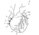
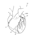
図3は、本発明の病変モデルが右冠動脈に配置された第1実施形態を示す模式図、図4は、右冠動脈に配置された病変モデルに対してPTCA術の訓練を行う手順を示す図、図5および図6は、狭窄型の病変モデルの各種構成を示す図(左図は縦断面図、右図は左図のA−A線断面図)、図7および図8は、閉塞型の病変モデルの各種構成を示す図(左図は縦断面図、右図は左図のA−A線断面図)、図9は、訓練後の病変モデルの状態を示す縦断面図、図10は、本発明の病変モデルを製造し、製造された病変モデルを管の内腔部に配置する方法を説明するための図、図11は、本発明の病変モデルを製造する他の製造方法を説明するための図、図12は、本発明の病変モデルを製造する際に用いられる押し子の他の構成を示す図、図13は、接続具の構成を説明するための図(図(a)は斜視図、図(B)は縦断面図)、図14は、接続機構の構成を説明するための図(図(a)は斜視図、図(B)は縦断面図)、図15は、本発明の病変モデルが左冠動脈の分岐部に配置された第2実施形態を示す模式図、図16は、分岐部に配置される病変モデルの各種構成を示す縦断面図、図17は、本発明の病変モデルが配置される、病変の好発部位を示すための図である。なお、以下の説明では、図3〜17図中の上側を「上」、下側を「下」と言う。また、図3、図15および図17には、冠動脈の形状および位置等が分かり易くなるように、心臓の形状についても併せて図示している。 FIG. 3 is a schematic diagram showing a first embodiment in which the lesion model of the present invention is placed in the right coronary artery, and FIG. 4 is a diagram showing a procedure for performing PTCA training on the lesion model placed in the right coronary artery. 5 and 6 are diagrams showing various configurations of a stenosis type lesion model (the left figure is a longitudinal sectional view, the right figure is a sectional view taken along the line AA of the left figure), and FIGS. 7 and 8 are occlusion types. (Left figure is a longitudinal sectional view, Right figure is a sectional view taken along line AA in the left figure), FIG. 9 is a longitudinal sectional view showing the state of a lesion model after training, FIG. FIG. 11 is a diagram for explaining a method of manufacturing the lesion model of the present invention and arranging the manufactured lesion model in the lumen of the tube, and FIG. 11 shows another manufacturing method of manufacturing the lesion model of the present invention. FIG. 12 for explanation, FIG. 12 is a diagram showing another configuration of the pusher used in manufacturing the lesion model of the present invention, FIG. The figure for demonstrating the structure of a connector (a figure (a) is a perspective view, the figure (B) is a longitudinal cross-sectional view), FIG. 14 is the figure (a figure (a) is a figure for demonstrating the structure of a connection mechanism. FIG. 15 is a schematic view showing a second embodiment in which the lesion model of the present invention is arranged at the bifurcation of the left coronary artery, and FIG. 16 is arranged at the bifurcation. FIG. 17 is a view for showing a site where a lesion is frequently generated, in which the lesion model of the present invention is arranged. In the following description, the upper side in FIGS. 3 to 17 is referred to as “upper” and the lower side is referred to as “lower”. 3, 15, and 17 also illustrate the shape of the heart so that the shape and position of the coronary artery can be easily understood.
冠動脈10は、大動脈5のバルサルバ洞において、左右に分岐する左冠動脈3および右冠動脈4からなる。
この冠動脈10は、前述した立体モデル成形材料の硬化物で構成される。
The
The
また、立体モデル成形材料としては、特に限定されないが、例えば、シリコーンエラストマー、シリコーンゲルのようなシリコーンゴム、ポリウレタンエラストマー、シリコーン樹脂、エポキシ樹脂、フェノール樹脂のような熱硬化性樹脂、ポリメタクリル酸メチル、ポリ塩化ビニル、ポリエチレンのような熱可塑性樹脂等が挙げられ、これらのうちの1種または2種以上を組み合わせて用いることができる。これらの中でも、特に、シリコーンゴムを用いるのが好ましい。この材料の硬化物で冠動脈10を構成することにより、冠動脈10は、透明性に優れ、かつ実際の冠動脈に近似した弾力性および柔軟性を発揮するものとなる。
The three-dimensional model molding material is not particularly limited. For example, silicone elastomer, silicone rubber such as silicone gel, polyurethane elastomer, silicone resin, epoxy resin, thermosetting resin such as phenol resin, polymethyl methacrylate, etc. And thermoplastic resins such as polyvinyl chloride and polyethylene, and one or more of these can be used in combination. Among these, it is particularly preferable to use silicone rubber. By configuring the
具体的には、シリコーンゴムで構成される冠動脈10の破断強度は、0.5〜3.0MPa程度であるのが好ましく、1.0〜2.0MPa程度であるのがより好ましい。
Specifically, the breaking strength of the
また、冠動脈10の破断伸びは、50〜300%程度であるのが好ましく、100〜200%程度であるのがより好ましい。
The breaking elongation of the
さらに、冠動脈10のショアA硬度(ASTMD2240に規定)は、10〜40程度であるのが好ましく、25〜35程度であるのがより好ましい。
Further, the Shore A hardness (specified in ASTM D2240) of the
さらに、冠動脈10の引張弾性率は、0.01〜5.0MPa程度であるのが好ましく、0.1〜3.0MPa程度であるのがより好ましい。
Furthermore, the tensile elastic modulus of the
また、冠動脈10の内径φは、特に限定されないが、0.5〜4.0mm程度に設定されるのが好ましく、1.0〜3.0mm程度に設定されるのがより好ましい。冠動脈10の内径φをかかる範囲内に設定することにより、実際のヒトの冠動脈に対応した訓練を確実に実施することができ、術者の技術向上が的確に図られる。
The inner diameter φ of the
右冠動脈4は、バルサルバ洞窟の1つである右冠動脈洞の上部より前方に出た後、右心耳に覆われて右心房と肺動脈の間を走行し、右房室間溝に沿って鋭縁部41を回り後下行枝42に向かい、後室間溝で左心室後壁および中隔の下側を養う血管を派生する。
The right
なお、この右冠動脈4において、右冠動脈4の入口から鋭縁部41までを半分にした上半分をSegment1(#1:Proximal)といい、その下半分をSegment2(#2:Middle)といい、鋭縁部41から後下行枝42で分岐するまでをSegment3(#3:distal)という。また、後下行枝42の分岐以降をSegment4といい、このSegment4は、#4AV・#4PD・#4PLの3つに分けられる。
In the right
また、左冠動脈3は、バルサルバ洞の1つである左冠動脈洞の上部より左前方に出て、前室間溝に入る左前下行枝31と、左回旋枝32とに分岐する。
The left
なお、大動脈5から左前下行枝31と左回旋枝32とに分岐するまでの間の部位を左主幹部33(Segment5)という。また、左前下行枝31は、Segment6〜10まで細分化されており、このうち左前下行枝31の本幹は、Segment6(#6:Proximal)、Segment7(#7:Middle)、Segment8(#8:distal)の3つに分類され、Segment6とSegment7との間からSegment9(#9:第1対角枝)が分岐し、Segment7とSegment8との間からSegment10(#10:第2対角枝)が分岐している。さらに、左回旋枝32は、Segment11〜15まで細分化されており、このうち左回旋枝32の本幹は、Segment11(#11:Proximal)、Segment13(#13:distal)の2つに分類され、Segment11とSegment13との接続部からSegment12(#12:obtuse marginal branch;OM)が分岐している。
A portion from the
<<第1実施形態>>
まず、本実施形態(第1実施形態)では、かかる構成の冠動脈10において、右冠動脈4のSegment2(#2:Middle)に本発明の病変モデル21が配置され、このSegment2の双方の端部に病変モデル21を介して接続部11が設けられている。
<< First Embodiment >>
First, in the present embodiment (the first embodiment), in the
かかる位置に配置された病変モデル21に対して、PTCA術の訓練が行われるが、かかる訓練は、以下に示すような手順で実施される。
PTCA surgery training is performed on the
[1] まず、大腿動脈にシースカテーテル(図示せず)を挿入、次いで、これにガイドカテーテル用ガイドワイヤ(図示せず)を挿入し、その先端を右冠動脈4の入口付近にまで進めた状態で、ガイドカテーテル用ガイドワイヤに沿わせてガイドカテーテル61を進め、その先端を右冠動脈4の入口に位置させる(図4(a)参照。)。
[1] First, a sheath catheter (not shown) is inserted into the femoral artery, then a guide catheter guide wire (not shown) is inserted into the femoral artery, and the distal end is advanced to the vicinity of the entrance of the right
[2] 次に、ガイドカテーテル用ガイドワイヤを抜去し、バルーンカテーテル用ガイドワイヤ62をガイドカテーテル61内に挿入してガイドカテーテル61の先端からバルーンカテーテル用ガイドワイヤ62を突出させ、さらに右冠動脈4に配置した病変モデル21を越えた位置にまでバルーンカテーテル用ガイドワイヤ62を進める(図4(b)参照。)。
[2] Next, the guide
[3] 次に、バルーンカテーテル用ガイドワイヤ62の基端(大腿動脈)側から挿通されたバルーンカテーテル63の先端部をガイドカテーテル61の先端から突出させ、さらにバルーンカテーテル用ガイドワイヤ62に沿って進め、バルーンカテーテル63のバルーン64を病変モデル21に位置させた後、バルーン64に、バルーンカテーテル63の基端側からバルーン膨張用の流体を注入することにより、バルーン64が膨張される(図4(c)参照。)。これにより、病変モデル21が押し広げられる。
[3] Next, the distal end portion of the
[4] 次に、バルーンカテーテル63の基端側からバルーン膨張用の流体を排出し、図4(d)に示すようにバルーン64を収縮させる。その後、バルーンカテーテル用ガイドワイヤ62、バルーンカテーテル63、ガイドカテーテル61およびシースカテーテルを大腿動脈側から抜去する。これにより、病変モデル21に血流路が形成される。
[4] Next, the balloon inflation fluid is discharged from the proximal end side of the
以上のような訓練に用いられる病変モデル21の形状は、その狭窄度に応じて、狭窄型または閉塞型のものに分類される。
The shape of the
以下、これら型の種類で分類して順次、病変モデル21の形状について説明する。
<狭窄型>
狭窄型の病変モデル21のうち、図5(a)に示す第1の構成の病変モデル21は、そのほぼ中心部に軸方向(長手方向)に貫通する貫通孔23を有し、その全体形状がほぼ筒状をなす筒状体である。
Hereinafter, the shape of the
<Stenosis type>
Of the stenosis-
かかる構成の病変モデル21では、この病変モデル21を右冠動脈(内腔部)4に配置した際に、貫通孔23の外周部を構成する筒状体により、右冠動脈4が狭窄される。
In the
この第1の構成の病変モデル21では、前記工程[3]において、バルーンカテーテル63をバルーンカテーテル用ガイドワイヤ62に沿って右冠動脈4内を進めて、バルーン64を右冠動脈4を狭窄する病変モデル21すなわち貫通孔23内に到達させ、その後バルーン64を膨らませることにより病変モデル21(貫通孔23)を拡張する訓練を行うのに好適である。
In the
病変モデル21の長さは、特に限定されないが、1〜100mm程度であるのが好ましく、5〜50mm程度であるのがより好ましい。病変モデル21の長さをかかる範囲内に設定することにより、より実際の病変部位(狭窄部位)の大きさに適した訓練を実施することができる。
The length of the
また、病変モデル21の外径φは、配置する右冠動脈4の内径φの大きさに応じて適宜設定され、特に限定されるものではないが、0.5〜5.0mm程度であるのが好ましく、1.0〜3.0mm程度であるのがより好ましい。
Further, the outer diameter φ of the
なお、かかる範囲内に設定される病変モデル21の外径φは、右冠動脈4の内径φよりも大きく設定されているのが好ましい。これにより、病変モデル21は、右冠動脈(内腔部)4に圧縮された状態で挿入され、その結果、病変モデル21が右冠動脈4内に確実に固定されることとなるため、訓練の際に、バルーンカテーテル用ガイドワイヤ62やバルーンカテーテル63の接触により病変モデル21が不本意に位置ずれしてしまうのを確実に防止することができる。
The outer diameter φ of the
さらに、病変モデル21の貫通孔23の内径φは、特に限定されないが、0.1〜2.0mm程度であるのが好ましく、0.3〜1.0mm程度であるのがより好ましい。貫通孔23の内径φをかかる範囲内に設定することにより、実際の狭窄部位の狭窄度に適した訓練を確実に実施することができ、術者の技術向上が的確に図られる。
Furthermore, the inner diameter φ of the through
次に、図5(b)に示す第2の構成の病変モデル21は、第1の構成の病変モデル21と同様に、その中心部に軸方向に貫通する貫通孔23を有し、その全体形状がほぼ筒状をなしているが、その両端部に、貫通孔23の孔径(外径)がその内部側から外部側に向かって漸増するテーパ部を備えており、病変モデル21の両端ではその幅が実質的に「0」となっている。
Next, similarly to the
換言すれば、貫通孔23は、その両端部において、ロート状をなしており、病変モデル21の両端部内周面が、病変モデル21の内側から両端部側に向かって傾斜する傾斜面22をそれぞれ有している。
In other words, the through-
この第2の構成の病変モデル21では、前記工程[3]において、バルーン64を貫通孔23に到達させる際に、病変モデル21の傾斜面22にバルーンカテーテル63を沿わせるようにしながら、バルーン64を貫通孔23内に到達させ、その後バルーン64を膨らませることにより病変モデル21(貫通孔23)を拡張する訓練を行うのに好適である。
In the
なお、傾斜面22は、特に限定されないが、貫通孔23の中心軸に対して、15°〜65°程度の角度で傾斜しているのが好ましく、22°〜55°程度の角度で傾斜しているのがより好ましい。これにより、実際の狭窄部位の形状により適した訓練を確実に実施することができる。
The
さらに、本実施形態では、病変モデル21の両端部にテーパ部を備えているが、かかる場合に限定されず、2つの端部のいずれか一方にテーパ部が設けられていればよい。
Furthermore, in this embodiment, although the taper part is provided in the both ends of the
また、第1の構成および第2の構成の病変モデル21では、貫通孔23が、そのほぼ中心部で軸方向(長手方向)にほぼ直行して貫通する場合について説明したが、かかる構成に限定されず、貫通孔23は如何なる位置に、如何なる形状で形成されていてもよく、例えば、貫通孔23は、縁部側に偏在(図6(a))していてもよいし、縁部でその一部が開放(図6(b))していてもよいし、蛇行(湾曲)(図6(c))していてもよいし、その途中で拡径および縮径(図6(d))していてもよい。
Moreover, in the
<閉塞型>
閉塞型の病変モデル21のうち、図7(a)に示す第3の構成の病変モデル21は、その中心部に軸方向(長手方向)に連続する孔23’を有し、この病変モデル21を右冠動脈4内に配置した際に、この孔23’の内面同士が密着していること以外は、前述した第1の構成の病変モデル21と同様の構成のものである。
<Occlusion type>
Among the occlusion
この第3の構成の病変モデル21では、上記のように、孔23’の内面同士が密着していることにより、この病変モデル21が配置された位置で右冠動脈4が閉塞される。
In the
この第3の構成の病変モデル21では、前記工程[3]において、バルーンカテーテル63をバルーンカテーテル用ガイドワイヤ62に沿って右冠動脈4内を進める際に、孔23’を押し広げながらバルーン64をこの孔23’内に到達させ、その後バルーン64を膨らませることにより病変モデル21(孔23’)を拡張する訓練を行うのに好適である。
In the
次に、図7(b)に示す第4の構成の病変モデル21は、孔23’の両端に、孔23’から連続する貫通孔25を有し、この貫通孔25の孔径がその内部側から端部側に向かって漸増していること以外は、前述した第3の構成の病変モデル21と同様の構成のものである。
Next, the
すなわち、第4の構成の病変モデル21は、第2の構成の病変モデル21と第3の構成の病変モデル21とを組み合わせた構成のものであり、孔23’の内面同士が密着し、かつ、その両端部が傾斜面22を備えるテーパ部で構成されるものである。
That is, the
この第4の構成の病変モデル21では、前記工程[3]において、バルーン64を孔23’に到達させる際に、病変モデル21の傾斜面22にバルーンカテーテル63を沿わせるようにしながら、その先端を孔23’の入口まで導入した後、孔23’を押し広げながらバルーン64を孔23’内に到達させ、その後バルーン64を膨らませることにより病変モデル21(貫通孔23)を拡張する訓練を行うのに好適である。
In the
なお、第3の構成および第4の構成の病変モデル21では、孔23’が、そのほぼ中心部で軸方向(長手方向)にほぼ直行して連続的に形成されている場合について説明したが、かかる構成に限定されるものではない。具体的には、軸方向に連続する孔23’に代えて、軸方向に連続する切れ目23”であってもよい。また、この切れ目23”は如何なる位置に、如何なる形状で形成されていてもよく、例えば、切れ目23”は、一文字状(図8(a))または十文字状(図8(b))をなしていてもよいし、U字状をなして縁部側に偏在(図8(c))していてもよいし、切れ目の一端が外周の一部で開放する(図8(d))形状をなしていてもよい。
In the
以上のような形状をなす各構成の病変モデル21は、本発明では、塑性変形可能な材料で構成されており、右冠動脈4に配置し、流路を確保するために拡張する訓練を行ったとき、前記拡張により拡張前の形状に戻らない程度に塑性変形するものである。
In the present invention, the
ここで、PTCA術では、バルーン64で病変モデル21を拡張した際に、病変モデル21の端部が外側に移動することによる移動部211の発生(プラークシフト、図9(a)参照。)や、病変モデル21の一部が断裂することによる解離部212の発生(図9(b)参照。)等を生じさせることなく、流路を確保する(血流を回復させる)ことが技術的に求められる。
Here, in the PTCA technique, when the
そこで、PTCA術の訓練に病変モデル21を用いれば、病変モデル21が塑性変形するため、前記工程[4]において、バルーンカテーテル用ガイドワイヤ62およびバルーンカテーテル63を病変モデル21から取り外した後にも、病変モデル21は、バルーン64で押し広げた形状を維持していることとなる。そのため、PTCA術の訓練の後に、病変モデル21に、移動部211や解離部212等が生じているか否かの評価をより確実に行え得るため、より質の高い訓練を実施することができる。
Therefore, if the
また、前記工程[3]におけるバルーン64の拡張を、目視やX線造影像で観察しながら訓練を実施でき、病変モデル21の拡張の度合いや、移動部211や解離部212等が生じているか否かの判断をその場で行い得るので、かかる観点からも、より質の高い訓練を実施することができる。
In addition, training can be performed while observing the expansion of the
なお、前記工程[4]により血流が回復された後の病変モデル21、すなわちPTCA術が施術された後の病変モデル21に対して、図9(c)に示すように、ステント81を留置することにより、病変モデル21の再狭窄や解離部212の解離を防止することができる。このようなステント81を留置する治療の訓練にも病変モデル21を用いることができ、かかる訓練に病変モデル21を用いれば、再狭窄や解離部212の解離が好適に防止されているか否かの評価をより確実に実施することができる。
In addition, as shown in FIG. 9C, the
また、塑性変形する病変モデル21は、これが配置されている右冠動脈4よりも、その弾性率が小さくなっているのが好ましい。人体内で形成される実際の病変部位(狭窄部位)は、主としてコレステロールが血管に沈着した沈着物で構成され、一般的に、その弾性率は、血管の弾性率よりも小さい。そのため、病変モデル21の弾性率を、右冠動脈4の弾性率よりも小さくすることにより、実際の病変部位の物理的性質に近似した訓練を確実に実施することができる。
Further, it is preferable that the
したがって、病変モデル21の圧縮弾性率は、0.001〜0.5MPa程度であるのが好ましく、0.01〜0.3MPa程度であるのがより好ましい。
Therefore, the compression elastic modulus of the
病変モデル21の物性値をかかる範囲内のもとのすることにより、病変モデル21の物理的性質は、実際の病変部位により近似した状態で塑性変形するものとなり、より質の高い訓練を実施することができる。
By making the physical property value of the
病変モデル21の構成材料は、上述したような物理的性質を病変モデル21に発揮させ得るもので、かつ可塑性を長時間に亘って持続し病変モデル21として成形後もその物理的性質が変わりにくいものが好ましい。
The constituent material of the
具体的には、シリコーン粘土、ゴム粘土、樹脂粘土および油粘土等が挙げられ、これらのうちの1種または2種以上を組み合わせて用いることができる。 Specific examples include silicone clay, rubber clay, resin clay, and oil clay, and one or more of these can be used in combination.
上記のうち、例えば、シリコーン粘土としては、シリコーンゴムとして、粘度が5000〜20万cSt(25℃)程度のポリオルガノシロキサンと、粘度が100万cSt(25℃)以上のポリオルガノシロキサンとを重量比で80:20〜40:60で混合したもの100重量部、無機充填材として、石英粉末、珪藻土、珪酸マグネシウム、炭酸カルシウム、タルクおよび雲母粉末等のうち1種または2種以上組み合わせたもの20〜100重量部、その他必要に応じて流動パラフィンとして10重量部を含有するものが挙げられる。また、かかる構成のシリコーン粘土は、上記のシリコーンゴム、無機充填材および必要に応じて流動パラフィンをそれぞれ用意し、これらを、ロールおよびニーダー等の通常のゴム混練りに使用される混練り機を使用して均一に混練りすることにより得ることができる。 Among the above, for example, as silicone clay, as silicone rubber, polyorganosiloxane having a viscosity of about 5000 to 200,000 cSt (25 ° C.) and polyorganosiloxane having a viscosity of 1 million cSt (25 ° C.) or more are weighted. 100 parts by weight mixed at a ratio of 80:20 to 40:60, 20 combined with one or more of quartz powder, diatomaceous earth, magnesium silicate, calcium carbonate, talc, mica powder, etc. as inorganic filler 20 ˜100 parts by weight, and others containing 10 parts by weight as liquid paraffin if necessary. In addition, the silicone clay having such a structure is prepared with the above-mentioned silicone rubber, inorganic filler, and liquid paraffin as required, and these are kneaders used for ordinary rubber kneading such as rolls and kneaders. It can be obtained by using and kneading uniformly.
なお、無機充填材の平均粒径は、特に限定されないが、0.1〜50μm程度であるのが好ましく、0.5〜30μm程度であるのがより好ましい。平均粒径が0.1μm未満であると、無機充填材の種類によっては、シリコーン粘土が硬すぎたり粘性が乏しくなるおそれがある。また、平均粒径が50μmを超えると、無機充填材の種類によっては、伸びのある物性が得にくくなるおそれがある。無機充填材の配合量は、少なすぎると好ましい粘土状物が得にくく、多すぎると硬くなりすぎるおそれがある。 In addition, although the average particle diameter of an inorganic filler is not specifically limited, It is preferable that it is about 0.1-50 micrometers, and it is more preferable that it is about 0.5-30 micrometers. If the average particle size is less than 0.1 μm, the silicone clay may be too hard or the viscosity may be poor depending on the type of the inorganic filler. On the other hand, if the average particle size exceeds 50 μm, depending on the type of the inorganic filler, it may be difficult to obtain stretched physical properties. When the blending amount of the inorganic filler is too small, it is difficult to obtain a preferable clay-like material, and when it is too large, there is a possibility that it becomes too hard.
また、流動パラフィンは、粘度の粘性を向上させる機能を有するが、この含有量を多くしすぎるとブリードし、手に付着したりすることがある。 Further, liquid paraffin has a function of improving the viscosity, but if this content is too large, it may bleed and adhere to the hand.
ゴム粘土としては、上記のシリコーンゴムの代わりに天然ゴムやブチルゴムを含有するものが挙げられる。 Examples of the rubber clay include those containing natural rubber or butyl rubber instead of the silicone rubber.
樹脂粘土としては、一般に、澱粉および/または穀粉と、酢酸ビニルエマルジョン系接着剤とを主材料として構成される粘土が挙げられる。澱粉ならびに穀粉としては、それぞれ、例えば、コーンスターチ、馬鈴薯澱粉、小麦澱粉、米澱粉、タピオカ澱粉および甘薯澱粉等、ならびに、小麦粉、とうもろこし粉、米粉およびそば粉等が挙げられる。酢酸ビニルエマルジョン系接着剤としては、例えば、酢酸ビニル樹脂エマルジョン、エチレン−酢酸ビニル共重合体エマルジョンおよびアクリル−酢酸ビニル共重合体エマルジョン等が挙げられる。 In general, the resin clay includes clay composed mainly of starch and / or flour and a vinyl acetate emulsion adhesive. Examples of the starch and cereal flour include corn starch, potato starch, wheat starch, rice starch, tapioca starch and sweet potato starch, and wheat flour, corn flour, rice flour and buckwheat flour, respectively. Examples of the vinyl acetate emulsion adhesive include a vinyl acetate resin emulsion, an ethylene-vinyl acetate copolymer emulsion, and an acrylic-vinyl acetate copolymer emulsion.
なお、これらの配合量は、澱粉や穀粉100重量部に対し、酢酸ビニルエマルジョン系接着剤が100〜150重量部程度であるのが好ましい。また、これらの材料の他、樹脂粘土には、無機物粉末、ロウおよび石鹸等が含まれていてもよい。無機物粉末としては、例えば、石英、カオリン、ゼオライト、珪藻土、タルク、ベントナイト、ホウ砂および岩石粉等が挙げられ、これらのうちの1種または2種以上を組み合わせて用いることができる。また、ロウとしては、蜜蝋等が挙げられる。石鹸としては、脂肪酸塩石鹸等が挙げられる。ただし、これらは、いずれもその配合量が10重量部未満となっているのが好ましい。 In addition, it is preferable that these compounding quantities are about 100-150 weight part of vinyl acetate emulsion adhesives with respect to 100 weight part of starch and flour. In addition to these materials, the resin clay may contain inorganic powder, wax, soap and the like. Examples of the inorganic powder include quartz, kaolin, zeolite, diatomaceous earth, talc, bentonite, borax, and rock powder, and one or more of these can be used in combination. Examples of the wax include beeswax. Examples of the soap include fatty acid salt soap. However, as for these, it is preferable that the compounding quantity is all less than 10 weight part.
油粘土としては、通常、クレー、炭酸カルシウム、セリサイト系粘土のような無機質充填剤と、石鹸および油成分とを練り合わせたものが用いられる。より詳しくは、油成分として、流動パラフィンおよび/またはマイクロクリスタリンワックスを、無機質充填剤100重量部に対し15〜45重量部程度含有し、石鹸として、アルカリ金属石鹸、アルカリ土類金属石鹸、アルミニウム石鹸のうちの1種または2種以上を組み合わせたものを、0.2〜15重量部程度含有し、さらにグリセリンを0.2〜10重量部程度含有するものが好ましく用いられる。 As the oil clay, a mixture of an inorganic filler such as clay, calcium carbonate, sericite clay, soap and an oil component is usually used. More specifically, liquid paraffin and / or microcrystalline wax is contained as an oil component in an amount of about 15 to 45 parts by weight with respect to 100 parts by weight of the inorganic filler, and the soap includes alkali metal soap, alkaline earth metal soap, aluminum soap. Of these, those containing about 0.2 to 15 parts by weight of one or a combination of two or more of them, and further containing about 0.2 to 10 parts by weight of glycerin are preferably used.
なお、上述したシリコーン粘度の具体例としては、透明粘土(日清アソシエイツ社製)が挙げられ、樹脂粘土の具体例としては、エクセレント(日清アソシエイツ社製)が挙げられる。 In addition, as a specific example of the above-mentioned silicone viscosity, transparent clay (manufactured by Nisshin Associates) is mentioned, and as a specific example of resin clay, excellent (manufactured by Nisshin Associates) is mentioned.
以上のような病変モデル21は、例えば、次のようにして、製造することができる。
[I] まず、外筒(シース)71と、外筒71内で摺動可能な、軸方向に貫通孔73が設けられた押し子72と、貫通孔73内に挿通されるワイヤ74とを用意し、図10(a)に示すように、外筒71内に押し子72を挿入した状態で、ワイヤ74を貫通孔73および外筒71内に挿通する。
The
[I] First, an outer cylinder (sheath) 71, a
[II] 次に、病変モデル21の構成材料である塑性変形可能な材料を、ワイヤ74および押し子72が挿入された状態の外筒71内に充填することで成形し、外筒71内に病変モデル21を得る(図10(b)参照。)。
[II] Next, a plastically deformable material that is a constituent material of the
ここで、本実施形態では、押し子72は、その先端が図10に示すように平坦面で構成されているため、病変モデル21は、第1の構成のものが製造される。
Here, in this embodiment, since the
また、塑性変形可能な材料を成形する際に、外筒71内でワイヤ74を蛇行させることにより、貫通孔23を蛇行させることができるし、ワイヤ74として拡径・縮径するものを用いることにより、貫通孔23を拡径・縮径させることができる。
Further, when molding a plastically deformable material, the through
[III] 次に、右冠動脈4のSegment2を接続部11で取り外し、この取り外されたSegment2内に、外筒71を挿入する(図10(c)参照。)。
[III] Next, the
[IV] 次に、ワイヤ74を、外筒71および貫通孔73内から抜き取り、その後、押し子72を、押圧操作して、外筒71内で先端方向に摺動させる。これにより、外筒71内から病変モデル21が押し出され、Segment2内に配置される(図10(d)参照。)。
[IV] Next, the
なお、外筒71の内面には、予め、剥離剤を用いたコーティング処理が施されているのが好ましい。これにより、押し子72の押圧操作により、病変モデル21に変形等が生じることなく、容易に外筒71内から病変モデル21を押し出すことができる。また、剥離剤としては、特に限定されず、例えば、シリコンオイル等を用いることができる。
The inner surface of the
以上のような工程を経て、右冠動脈4のSegment2内、すなわち、管の内腔部に、製造された病変モデル21が配置される。
The manufactured
また、第2の構成の病変モデル21を製造する場合、図11(a)に示すように、押し子72として先端部がその先端側に向かって縮径するものを2つ用意し、前記工程[II]を以下のような工程[II’]に変更することにより、第2の構成の病変モデル21を製造することができる。
When the
[II’] 先端部が先端側に向かって縮径する押し子72およびワイヤ74が挿入された状態の外筒71内に、病変モデル21の構成材料である塑性変形可能な材料を充填した後、さらに、もう1つの押し子72を、先に挿入された押し子72とは、反対側から挿入する。その後、この状態で、前記流体材料を成形することにより、外筒71内に、第2の構成の病変モデル21を得ることができる(図11(b)参照。)。
[II ′] After filling the
さらに、貫通孔23が縁部側に偏在している第2の構成の病変モデル21を製造する場合、図12のように、貫通孔73も押し子72内で縁部側に偏在するものを用いるようにすれば、かかる構成の病変モデル21を容易に製造することができる。
Furthermore, when manufacturing the
また、接続部11は、上述した病変モデル21の製造方法で説明したように、病変モデル21を右冠動脈4のSegment2(#2:Middle)の位置で配置し得るように、Segment2の部分で着脱可能とするため、Segment2の双方の端部にそれぞれ設けられている(図3参照。)。すなわち、Segment2は、一端がSegment1の端部と、他端がSegment3の端部と、それぞれ、接続部11で接続され、これにより、右冠動脈4から着脱可能な構成となっている。
Further, as described in the manufacturing method of the
このような接続部11は、Segment2の部分で着脱可能で、かつ接続すべき各端部同士を液密に接続し得る構成であれば、いかなる構成のものであってもよいが、例えば、以下に示すような接続具または接続機構を用いた構成とすることにより、液密に接続することができる。
Such a
<接続具>
接続具12は、その中心部に軸方向(長手方向)に貫通する貫通孔14を有し、その全体形状がほぼ筒状をなす本体13と、本体13のほぼ中央に設けられたフランジ15とを有するものである。
<Connector>
The
本体13は、その両端部で縮径する縮径部を有しており、この縮径部の外径が右冠動脈4の内径よりも小さく設定され、縮径部よりもフランジ15側(内側)ではその外径が右冠動脈4の内径よりも大きく設定される。
The
かかる構成の接続具12に対して、右冠動脈4の先端(切断面)から右冠動脈4を、前記先端部からフランジ15側に向かって挿入すると、右冠動脈4の内径が拡径する。これにより、本体13の外周面と右冠動脈4の内周面とが互いに密着することとなるため、接続具12により、右冠動脈4の端部同士が液密に接続される。
When the right
接続具12の構成材料としては、特に限定されないが、各種樹脂材料が好適に用いられ、具体的には、ポリエチレン、ポリプロピレン、エチレン−プロピレン共重合体、エチレン−酢酸ビニル共重合体(EVA)等のポリオレフィン、ポリ塩化ビニル、ポリ塩化ビニリデン、ポリスチレン、ポリアミド、ポリイミド、ポリアミドイミド、ポリカーボネート、ポリ−(4−メチルペンテン−1)、アイオノマー、アクリル系樹脂、ポリメチルメタクリレート、アクリロニトリル−ブタジエン−スチレン共重合体(ABS樹脂)、アクリロニトリル−スチレン共重合体(AS樹脂)、ブタジエン−スチレン共重合体、ポリエチレンテレフタレート(PET)、ポリブチレンテレフタレート(PBT)、ポリシクロヘキサンテレフタレート(PCT)等のポリエステル、ポリエーテル、ポリエーテルケトン(PEK)、ポリエーテルエーテルケトン(PEEK)、ポリエーテルイミド、ポリアセタール(POM)、ポリフェニレンオキシド、変性ポリフェニレンオキシド、ポリサルフォン、ポリエーテルサルフォン、ポリフェニレンサルファイド、ポリアリレート、芳香族ポリエステル(液晶ポリマー)、ポリテトラフルオロエチレンおよびポリフッ化ビニリデン等の各種樹脂材料が挙げられ、これらのうちの1種または2種以上を組み合わせて用いることができる。
Although it does not specifically limit as a constituent material of the
<接続機構>
接続機構16は、切断された右冠動脈4の各先端(切断面)に設けられたフランジ17と、一方の右冠動脈4に回転可能に支持されたリング状部材(第1のリング状部材)18と、他方の右冠動脈4にフランジ17と接触するように固着されたリング状部材(第2のリング状部材)19とを有するものである。
<Connection mechanism>
The
リング状部材18には、フランジ17側に開放する開放部が形成されており、この開放部の内面には雌ネジ181が形成されている。
The ring-shaped
また、リング状部材19には、その外周面に雄ネジ191が形成され、さらに、このリング状部材19がリング状部材18に形成された開放部に挿入可能な大きさに設定されることにより、リング状部材19がリング状部材18の開放部に挿入(螺入)し得るようになっている。
In addition, the ring-shaped
かかる構成の接続機構16において、2つのフランジ17の端面同士を接触させた状態で、リング状部材18、19にそれぞれ形成された雌ネジ181と雄ネジ191とを螺合することにより、2つのフランジ17の端面同士が互いに密着することとなるため、接続機構16により、右冠動脈4の端部同士が液密に接続される。
In the
接続機構16の各種構成部材の構成材料としては、前述した接続具12の構成材料と同様のものが好適に用いられる。
As the constituent material of the various constituent members of the
<<第2実施形態>>
次に、右冠動脈4のSegment2(#2:Middle)とは異なり、左冠動脈3に病変モデル21が配置された第2実施形態について説明する。
<< Second Embodiment >>
Next, unlike the Segment 2 (# 2: Middle) of the right
以下、左冠動脈3に病変モデル21が配置された第2実施形態について、前記第1実施形態との相違点を中心に説明し、同様の事項については、その説明を省略する。
Hereinafter, the second embodiment in which the
すなわち、本実施形態(第2実施形態)では、図15に示すように、左冠動脈3のSegment6がSegment7とSegment9とに分岐する分岐部(バイファケーション)34に病変モデル21が配置され、この病変モデル21を介してSegment6、Segment7およびSegment9の途中にそれぞれ接続部11が設けられていること以外は、前記第1実施形態と同様の構成となっている。
That is, in the present embodiment (second embodiment), as shown in FIG. 15, the
このような分岐部34に配置される病変モデル21は、例えば、図16(a)に示すような第5の構成のものや、図16(b)に示すような第6の構成のものが挙げられる。
For example, the
第5の構成の病変モデル21は、一端から他端に向かって拡径する筒状体をなし、その内部に形成される貫通孔23も同様に拡径すること以外は、前述した第2の構成の病変モデル21と同様の構成のものである。かかる構成の第5の構成の病変モデル21は、分岐部34の先端が、その口径が拡径する他端側に挿入するようにして配置される。
The
また、第6の構成の病変モデル21は、その口径が拡径する他端側でY字状に分岐し、その内部に形成される貫通孔23も同様にY字状に分岐するような構成となっていること以外は、前述した第5の構成の病変モデル21と同様の構成のものである。かかる構成の第6の構成の病変モデル21は、左冠動脈3の分岐部34と、病変モデル21のY字状をなす分岐部とが互いに当接するようにして配置される。
Further, the
これら第5および第6の構成の病変モデル21では、通常、まず、バルーンカテーテル用ガイドワイヤ62をSegment6からSegment7側に挿通し、このバルーンカテーテル用ガイドワイヤ62に沿ってバルーンカテーテル63を進めることにより、バルーン64を病変モデル21の位置に到達させ、さらにこの位置でバルーン64を膨らませて、病変モデル21のSegment7側を拡張させる。次いで、バルーンカテーテル用ガイドワイヤ62をSegment6からSegment9側に挿通し、上記と同様にしてバルーン64を病変モデル21の位置に到達させた後、膨らませて、病変モデル21のSegment9側を拡張することにより、流路を確保する訓練が実施される。
In the
このような訓練では、病変モデル21のSegment7側を拡張させる際に、バルーン64が病変モデル21のSegment9側をも押し潰し、これに起因して病変モデル21のSegment9側の端部が移動(プラークシフト)し、最終的にはSegment9が閉塞されてしまうことを回避するのに高度な技術が求められる。このような訓練に本発明の病変モデル21を適用すると、病変モデル21は、拡張により拡張前の形状に戻らない程度に塑性変形するものであるため、病変モデル21のSegment7側を拡張させた際に、Segment9に閉塞が生じているか否かの評価をより確実に行え得る。したがって、かかる訓練に本発明の病変モデルを適用すれば、より質の高い訓練を確実に実施することができる。
In such training, when the
なお、本実施形態では、接続部11は、前述の通り、病変モデル21を分岐部34に配置し得るように、Segment6、Segment7およびSegment9の途中にそれぞれ設けられ、これにより、接続部11において、分岐部34を含むSegment6、Segment7およびSegment9の一部が左冠動脈3から着脱可能な構成となっている(図15参照。)。
In the present embodiment, as described above, the
また、本実施形態で説明した第5の構成および第6の構成の病変モデル21も、前記第1実施形態で説明した病変モデル21と同様にして製造することができる。例えば、テーパー状に拡径する外筒と、外筒のテーパー状の内径に適合する外径を有し、先端が縮径する押し子と、貫通孔に挿通されるワイヤを用意し、病変モデル21の構成材料である塑性変形可能な材料を外筒内に充填することで形成することができる。また、図16(b)の分岐部34に設置する病変モデル213は、別途、塑性変形可能な材料で分岐部34を被覆することにより形成することができる。
The
なお、前記第1実施形態では、病変モデル21が右冠動脈4のSegment2(#2:Middle)に配置されている場合について説明し、前記第2実施形態では、病変モデル21が左冠動脈3のSegment6(#6)がSegment7(#7)とSegment9(#9)とに分岐する分岐部34に配置されている場合について説明したが、病変モデル21を配置する位置はかかる位置に限定されず、冠動脈の狭窄または閉塞が高確率で生じる好発部位に病変モデル21を配置して、好発部位に応じた訓練を実施すれば良い。なお、このような病変モデル21が配置される好発部位としては、例えば、図17に示す●印の位置が挙げられる。
In the first embodiment, the case where the
以上のように、本発明の病変モデルを用いれば、冠動脈(血管)等の内腔部を有する管を用いた立体モデルにおいて、病変部位の物理的性質に近似した病変モデルを、その任意の位置に任意の形状で配置することができる。そのため、この病変モデルを備える立体モデルを用いて、さまざまな患者の病態に対応した訓練を実施できることから、術者は、患者に施す手術以外の場で、より高度な技術を習得することができる。 As described above, by using the lesion model of the present invention, in a three-dimensional model using a tube having a lumen such as a coronary artery (blood vessel), a lesion model that approximates the physical properties of a lesion site can be obtained at an arbitrary position. Can be arranged in any shape. For this reason, since a three-dimensional model including this lesion model can be used to perform training corresponding to various patient pathologies, the surgeon can acquire more advanced techniques in a place other than the surgery performed on the patient. .
以上、本発明の病変モデルを図示の実施形態について説明したが、本発明は、これに限定されるものではなく、病変モデルを構成する各部は、同様の機能を発揮し得る任意の構成のものと置換することができる。また、任意の構成物が付加されていてもよい。 As mentioned above, although the lesion model of this invention was demonstrated about embodiment of illustration, this invention is not limited to this, Each part which comprises a lesion model is the thing of arbitrary structures which can exhibit the same function Can be substituted. Moreover, arbitrary components may be added.
また、前記実施形態では、血管(冠動脈)を再現して人工的に製造された管に、本発明の病変モデルを配置して訓練を実施する場合について説明したが、かかる場合に限定されず、ヒトを除く動物の生体が有する管や、ヒトの死体が有する管、すなわち、ヒトの生体が有する管を除く管に本発明の病変モデルを配置して訓練を実施するようにしてもよい。 Further, in the embodiment, the case where the training is performed by arranging the lesion model of the present invention on a tube artificially manufactured by reproducing a blood vessel (coronary artery) is not limited to such a case, Training may be carried out by placing the lesion model of the present invention in a tube of an animal body other than a human body or a tube of a human cadaver, that is, a tube other than a tube of a human body.
なお、本発明の病変モデルは、前記実施形態で説明したように、病変モデルに流路を確保するために拡張する訓練に好適に用い得るように、前記拡張により拡張前の形状に戻らない程度に塑性変形するものとしたが、このような本発明の病変モデルは、当然、病変モデルの拡張を伴わない、当該病変モデルにガイドワイヤを越えて通過させる訓練等にも適用される。 Note that, as described in the above embodiment, the lesion model of the present invention does not return to the shape before expansion due to the expansion so that the lesion model can be suitably used for training to expand to secure a flow path in the lesion model. The lesion model of the present invention is naturally applied to training or the like in which the lesion model is passed through the guide wire without expansion of the lesion model.
10 冠動脈
11 接続部
12 接続具
13 本体
14 貫通孔
15 フランジ
16 接続機構
17 フランジ
18、19 リング状部材
181 雌ネジ
191 雄ネジ
21 病変モデル
211 移動部
212 解離部
213 病変モデル
22 傾斜面
23 貫通孔
23’ 孔
23” 切れ目
24 側面
25 貫通孔
3 左冠動脈
31 左前下行枝
32 左回旋枝
33 左主幹部
34 分岐部
4 右冠動脈
41 鋭縁部
42 後下行枝
5 大動脈
61 ガイドカテーテル
62 バルーンカテーテル用ガイドワイヤ
63 バルーンカテーテル
64 バルーン
71 外筒
72 押し子
73 貫通孔
74 ワイヤ
81 ステント
DESCRIPTION OF
Claims (9)
当該病変モデルは、主としてシリコーン粘土、樹脂粘土および油粘土のうちの少なくとも1種で構成される塑性変形可能な材料で構成されており、
当該病変モデルを前記内腔部に配置し、流路を確保するために拡張する訓練を行ったとき、前記拡張により拡張前の形状に戻らない程度に塑性変形するものであることを特徴とする病変モデル。 A lesion model that is disposed in the lumen portion of a tube having a lumen portion and has a shape that narrows or occludes the lumen portion when disposed in the lumen portion;
The lesion model is composed of a plastically deformable material mainly composed of at least one of silicone clay, resin clay and oil clay .
When the lesion model is placed in the lumen part and subjected to training for expansion to ensure a flow path, it is plastically deformed to the extent that it does not return to the shape before expansion due to the expansion. Lesion model.
Priority Applications (6)
| Application Number | Priority Date | Filing Date | Title |
|---|---|---|---|
| JP2009034659A JP5289997B2 (en) | 2009-02-17 | 2009-02-17 | A lesion model placed in the lumen of the duct |
| CN201080008048.7A CN102317992B (en) | 2009-02-17 | 2010-02-04 | Biological model for training and method for producing biological model for training |
| EP18208241.2A EP3489933B1 (en) | 2009-02-17 | 2010-02-04 | Biological model for training |
| PCT/JP2010/051626 WO2010095519A1 (en) | 2009-02-17 | 2010-02-04 | Biological model for training and method for producing biological model for training |
| US13/201,930 US8808004B2 (en) | 2009-02-17 | 2010-02-04 | Biological model for training and production method of biological model for training |
| EP10743647.9A EP2400475A4 (en) | 2009-02-17 | 2010-02-04 | Biological model for training and method for producing biological model for training |
Applications Claiming Priority (1)
| Application Number | Priority Date | Filing Date | Title |
|---|---|---|---|
| JP2009034659A JP5289997B2 (en) | 2009-02-17 | 2009-02-17 | A lesion model placed in the lumen of the duct |
Publications (2)
| Publication Number | Publication Date |
|---|---|
| JP2010187878A JP2010187878A (en) | 2010-09-02 |
| JP5289997B2 true JP5289997B2 (en) | 2013-09-11 |
Family
ID=42814598
Family Applications (1)
| Application Number | Title | Priority Date | Filing Date |
|---|---|---|---|
| JP2009034659A Active JP5289997B2 (en) | 2009-02-17 | 2009-02-17 | A lesion model placed in the lumen of the duct |
Country Status (1)
| Country | Link |
|---|---|
| JP (1) | JP5289997B2 (en) |
Families Citing this family (6)
| Publication number | Priority date | Publication date | Assignee | Title |
|---|---|---|---|---|
| JP5136993B2 (en) * | 2009-03-20 | 2013-02-06 | 学校法人早稲田大学 | Simulated stenotic blood vessel and method for producing the same |
| US8685787B2 (en) | 2010-08-25 | 2014-04-01 | Semiconductor Energy Laboratory Co., Ltd. | Manufacturing method of semiconductor device |
| JP5749909B2 (en) * | 2010-09-24 | 2015-07-15 | テルモ株式会社 | Simulated human body |
| JP2012189909A (en) * | 2011-03-11 | 2012-10-04 | Asahi Intecc Co Ltd | Vascular lesion model |
| CN113781880B (en) * | 2021-06-28 | 2022-11-11 | 中山大学 | Preparation method of atherosclerotic plaque model |
| WO2023017600A1 (en) * | 2021-08-12 | 2023-02-16 | 朝日インテック株式会社 | Vascular lesion model |
Family Cites Families (4)
| Publication number | Priority date | Publication date | Assignee | Title |
|---|---|---|---|---|
| JPH0550477U (en) * | 1991-12-04 | 1993-07-02 | 株式会社高研 | Cardiovascular model |
| JP2001343891A (en) * | 2000-06-02 | 2001-12-14 | Medical Sense:Kk | Ptca trainer |
| DE10148341A1 (en) * | 2001-09-29 | 2003-04-24 | Friedhelm Brassel | Process for the production of a model system for vascular malformations |
| JP5024700B2 (en) * | 2007-03-26 | 2012-09-12 | 学校法人関西医科大学 | Cardiovascular simulation model |
-
2009
- 2009-02-17 JP JP2009034659A patent/JP5289997B2/en active Active
Also Published As
| Publication number | Publication date |
|---|---|
| JP2010187878A (en) | 2010-09-02 |
Similar Documents
| Publication | Publication Date | Title |
|---|---|---|
| WO2010095519A1 (en) | Biological model for training and method for producing biological model for training | |
| JP5289997B2 (en) | A lesion model placed in the lumen of the duct | |
| JP5290103B2 (en) | Biological model for training | |
| US8568326B2 (en) | Intravascular ultrasound pigtail catheter | |
| Robinson et al. | Patient-specific design of a soft occluder for the left atrial appendage | |
| JP5290077B2 (en) | Biological model for training and manufacturing method of biological model for training | |
| JP5452029B2 (en) | A lesion model placed in the lumen of the duct | |
| JP5136993B2 (en) | Simulated stenotic blood vessel and method for producing the same | |
| WO2009119908A1 (en) | Three-dimensional model of body tissue and method of producing the same | |
| JP2017509366A (en) | Catheter assembly for vascular access site creation | |
| JP2010508910A (en) | Devices and methods for accessing and treating aneurysms | |
| JP5290076B2 (en) | Biological model for training | |
| US20110251492A1 (en) | Ultrasound assessment of lumens to facilitate repair or replacement | |
| TW202145964A (en) | Introducer having controllable occlusion with perfusion capabilities | |
| US20120095334A1 (en) | Controlled inflation of an expandable member during a medical procedure | |
| CN109481828A (en) | A kind of novel seal wire and its application | |
| CN202191581U (en) | Multi-layer balloon dilation catheter | |
| US20110276127A1 (en) | Multiple inflation of an expandable member as a precursor to an implant procedure | |
| US20170080180A1 (en) | Catheter with asymmetric cross-section | |
| Cai et al. | Comparative analysis of three different optimization procedures for coronary bifurcation provisional stenting: insights from micro-computed tomography and optical coherence tomography imaging of bench deployments | |
| WO2009149645A1 (en) | A coated tuber for the bifurcated stent and the method for cutting membrane | |
| EP3300057B1 (en) | Use of a simulated animal organ | |
| Barbanti et al. | Interventions to reduce major vascular complications of TAVR | |
| JP2002143314A (en) | Dilation catheter | |
| Holoshitz et al. | Edwards SAPIEN XT Valve Implantation in the Pulmonary Position |
Legal Events
| Date | Code | Title | Description |
|---|---|---|---|
| A621 | Written request for application examination |
Free format text: JAPANESE INTERMEDIATE CODE: A621 Effective date: 20120110 |
|
| A131 | Notification of reasons for refusal |
Free format text: JAPANESE INTERMEDIATE CODE: A131 Effective date: 20130205 |
|
| A521 | Request for written amendment filed |
Free format text: JAPANESE INTERMEDIATE CODE: A523 Effective date: 20130405 |
|
| TRDD | Decision of grant or rejection written | ||
| A01 | Written decision to grant a patent or to grant a registration (utility model) |
Free format text: JAPANESE INTERMEDIATE CODE: A01 Effective date: 20130528 |
|
| A61 | First payment of annual fees (during grant procedure) |
Free format text: JAPANESE INTERMEDIATE CODE: A61 Effective date: 20130605 |
|
| R150 | Certificate of patent or registration of utility model |
Ref document number: 5289997 Country of ref document: JP Free format text: JAPANESE INTERMEDIATE CODE: R150 |
|
| R250 | Receipt of annual fees |
Free format text: JAPANESE INTERMEDIATE CODE: R250 |
|
| R250 | Receipt of annual fees |
Free format text: JAPANESE INTERMEDIATE CODE: R250 |
|
| R250 | Receipt of annual fees |
Free format text: JAPANESE INTERMEDIATE CODE: R250 |
|
| R250 | Receipt of annual fees |
Free format text: JAPANESE INTERMEDIATE CODE: R250 |
|
| R250 | Receipt of annual fees |
Free format text: JAPANESE INTERMEDIATE CODE: R250 |
|
| R250 | Receipt of annual fees |
Free format text: JAPANESE INTERMEDIATE CODE: R250 |