JP5289983B2 - Electrochemical cell - Google Patents
Electrochemical cell Download PDFInfo
- Publication number
- JP5289983B2 JP5289983B2 JP2009003325A JP2009003325A JP5289983B2 JP 5289983 B2 JP5289983 B2 JP 5289983B2 JP 2009003325 A JP2009003325 A JP 2009003325A JP 2009003325 A JP2009003325 A JP 2009003325A JP 5289983 B2 JP5289983 B2 JP 5289983B2
- Authority
- JP
- Japan
- Prior art keywords
- electrode
- reference electrode
- positive
- negative
- resistance
- Prior art date
- Legal status (The legal status is an assumption and is not a legal conclusion. Google has not performed a legal analysis and makes no representation as to the accuracy of the status listed.)
- Active
Links
Images


Classifications
-
- Y—GENERAL TAGGING OF NEW TECHNOLOGICAL DEVELOPMENTS; GENERAL TAGGING OF CROSS-SECTIONAL TECHNOLOGIES SPANNING OVER SEVERAL SECTIONS OF THE IPC; TECHNICAL SUBJECTS COVERED BY FORMER USPC CROSS-REFERENCE ART COLLECTIONS [XRACs] AND DIGESTS
- Y02—TECHNOLOGIES OR APPLICATIONS FOR MITIGATION OR ADAPTATION AGAINST CLIMATE CHANGE
- Y02E—REDUCTION OF GREENHOUSE GAS [GHG] EMISSIONS, RELATED TO ENERGY GENERATION, TRANSMISSION OR DISTRIBUTION
- Y02E60/00—Enabling technologies; Technologies with a potential or indirect contribution to GHG emissions mitigation
- Y02E60/10—Energy storage using batteries
Landscapes
- Electric Double-Layer Capacitors Or The Like (AREA)
- Secondary Cells (AREA)
Description
本発明は、電池、キャパシタ等の内部抵抗を正極、負極、電解液(セパレータ)の各抵抗に、簡便かつ精度良く同時に分離可能な電気化学セルに関する。 The present invention relates to an electrochemical cell that can easily and accurately simultaneously separate internal resistances of batteries, capacitors, and the like into resistances of a positive electrode, a negative electrode, and an electrolyte (separator).
近年、ハイブリッド電気自動車、瞬時停電バックアップ等の大電流負荷用途に向け、最先端蓄電デバイスであるリチウムイオン電池、リチウムイオンキャパシタ、電気二重層キャパシタ等の開発が加速している。この開発において、蓄電デバイスの入出力特性は最も重要な特性となり、迅速かつ有用な入出力特性評価、解析手法が求められている。従来、入出力特性は、蓄電デバイスに複数の充電電流(入力)あるいは放電電流(出力)を印加することにより得られる充電カーブあるいは放電カーブを解析・計算し評価されており、その評価は煩雑かつ手間のかかる作業であった。矢田は、入出力特性と内部抵抗を直接に関係づける評価手法として、直流電流印加を休止した時の電圧変化から内部抵抗の時間依存性を測定する直流内部抵抗測定法(電流休止法)の適用を提案している(非特許文献1)。この非特許文献1において休止直後から1秒までの電圧変化から算出される抵抗を休止法抵抗の「オーム成分」、1秒以降の電圧変化から算出される抵抗を休止法抵抗の「平衡成分」と定義されている。この電流休止法によれば、この方法により得られる直流内部抵抗(休止法抵抗)の時間変化を用いて、実際の入出力特性を予測することが可能である(非特許文献2、3)。このように直流内部抵抗(休止法抵抗)は実際の入出力特性と密接に関係するものであり、その評価・解析は特に高出力蓄電デバイスでは非常に重要となってきている。
In recent years, development of lithium-ion batteries, lithium-ion capacitors, electric double layer capacitors, etc., which are state-of-the-art power storage devices, has been accelerated toward high-current load applications such as hybrid electric vehicles and instantaneous power failure backups. In this development, the input / output characteristics of power storage devices are the most important characteristics, and rapid and useful input / output characteristics evaluation and analysis methods are required. Conventionally, input / output characteristics have been evaluated by analyzing and calculating a charge curve or discharge curve obtained by applying a plurality of charging currents (inputs) or discharging currents (outputs) to an electricity storage device. It was a laborious work. As an evaluation method that directly correlates input / output characteristics and internal resistance, Yada applied the DC internal resistance measurement method (current pause method) that measures the time dependence of internal resistance from the voltage change when DC current application was paused. (Non-Patent Document 1). In this
一方、蓄電デバイスの内部抵抗には,正極に起因する内部抵抗(正極抵抗)、負極に起因する内部抵抗(負極抵抗)、そして,電解液を含むセパレータに起因する内部抵抗(セパレータ抵抗)がある。各抵抗は蓄電デバイスの入出力特性を決定する基本要素である。従来、これら抵抗の解析は正極、負極、セパレータを個別で解析し、この解析情報からデバイス内における上記各抵抗を推定していた。これは内部抵抗、特に入出力特性と直接関係づけられる直流内部抵抗(休止法抵抗)を、デバイス内で分離し、かつ、同時に各抵抗(正極抵抗、負極抵抗、セパレータ抵抗)を評価することが難しいことによるものである。この課題に対し、矢田は非特許文献1において、四極セルによる分離手法を提案、報告している。この四極セルの構造は正極、負極以外に正極に近い位置に配置された正参照極、負極に近い位置に配置された負参照極の2つの参照極を有している。この四極セルを用いれば、正極抵抗、負極抵抗、セパレータ抵抗を、同時に分離することが可能とされており、この四極セルに対し、例えば、上記電流休止法を適用すれば、入出力特性と直接関係づけられるデバイス全体の休止法抵抗を、正極の休止法抵抗、負極の休止法抵抗、セパレータの休止法抵抗に分離することができ、より詳細な抵抗解析(入出力特性解析)が可能となる。
On the other hand, the internal resistance of the electricity storage device includes an internal resistance due to the positive electrode (positive electrode resistance), an internal resistance due to the negative electrode (negative electrode resistance), and an internal resistance due to the separator containing the electrolytic solution (separator resistance). . Each resistor is a basic element that determines the input / output characteristics of the electricity storage device. Conventionally, in the analysis of these resistances, the positive electrode, the negative electrode, and the separator are individually analyzed, and the respective resistances in the device are estimated from this analysis information. This separates the internal resistance, especially the DC internal resistance (quiescent resistance), which is directly related to the input / output characteristics, within the device and at the same time evaluates each resistance (positive resistance, negative resistance, separator resistance). This is due to difficulties. In response to this problem, Yada proposed and reported a separation method using a quadrupole cell in
この四極セルに関して特許文献1には、正極、負極、及び少なくとも2つの参照極を有し、少なくとも1つの参照極は正極の近傍に位置し、少なくとも1つの他の参照極は負極の近傍に位置することを特徴とし、正極と負極との極間(D)が1mm以下であり、正極の近傍に位置する参照極と正極との距離、及び、負極の近傍に位置する参照極と負極との距離の少なくともいずれか一方が、D以下である電気化学セルが開示されている。特許文献1に開示されている具体例では、正極の近傍に位置する参照極の表面は正極表面より内側にあり、負極の近傍に位置する参照極の表面は負極表面より内側にある。しかし、このセルを実際組み立てた場合、参照極の位置決め(正極と正極の近傍に位置する参照極との位置関係・距離、あるいは、負極と負極の近傍に位置する参照極との位置関係・距離)が難しく、参照極の位置決めが容易であり、かつ、精度良く抵抗を分離可能な電気化学セルが必要とされていた。
With respect to this quadrupole cell,
上記のごとく、正極、負極、及び少なくとも2つの参照極を有し、少なくとも1つの参照極は正極の近傍に位置し、少なくとも1つの他の参照極は負極の近傍に位置する電気セルを用いて、蓄電デバイスの内部抵抗を、同時にデバイス内で分離し、各抵抗(正極抵抗、負極抵抗、セパレータ抵抗)を評価する手法が知られている。また、正極、負極及び少なくとも1つの正参照極と少なくとも1つの負参照極とを有し、正参照極は正極面上の近傍に、負参照極は負極面上の近傍に配置された四極セルの構造に関して非特許文献1に開示されている。このように、正参照極を正極面上の近傍に、負参照極を負極面上の近傍に配置した場合、正極抵抗、負極抵抗、セパレータ抵抗をデバイス内で同時に分離評価することが可能であり、参照極の位置決めは容易になるものの、各抵抗の測定精度、分離精度に課題があった。本発明の目的は電池、キャパシタ等の内部抵抗を正極、負極、電解液(セパレータ)の各抵抗を簡便にかつ精度良く同時に分離可能な電気化学セルを提供することにある。
As described above, using an electric cell having a positive electrode, a negative electrode, and at least two reference electrodes, wherein at least one reference electrode is located in the vicinity of the positive electrode and at least one other reference electrode is located in the vicinity of the negative electrode. A method is known in which the internal resistance of the electricity storage device is simultaneously separated in the device and each resistance (positive electrode resistance, negative electrode resistance, separator resistance) is evaluated. A quadrupole cell having a positive electrode, a negative electrode, and at least one positive reference electrode and at least one negative reference electrode, the positive reference electrode being disposed in the vicinity on the positive electrode surface, and the negative reference electrode being disposed in the vicinity on the negative electrode surface This structure is disclosed in
本発明者は、上記の様な従来技術の問題点に留意しつつ研究を進めた結果、正極、負極及び少なくとも2つの参照極を有し、少なくとも1つの参照極は、正極面上の近傍に配置されている正参照極であり、少なくとも1つの参照極は、負極面上の近傍に配置されている負参照極である電気化学セルにおいて、参照極の形状、位置が特定条件内にあるとき、電池、キャパシタ等の内部抵抗を正極、負極、電解液(セパレータ)の各抵抗に簡便にかつ精度良く同時に分離可能であることを見出し本発明に至った。 As a result of conducting research while paying attention to the problems of the prior art as described above, the present inventor has a positive electrode, a negative electrode, and at least two reference electrodes, and at least one reference electrode is located near the positive electrode surface. In an electrochemical cell that is a positive reference electrode that is disposed and at least one reference electrode is a negative reference electrode disposed in the vicinity on the negative electrode surface, when the shape and position of the reference electrode are within specific conditions The present inventors have found that internal resistances of batteries, capacitors, etc. can be easily and accurately separated into positive, negative, and electrolytic solution (separator) resistances at the same time.
すなわち本発明は、以下の構成からなることを特徴とし、上記課題を解決するものである。 That is, the present invention is characterized by having the following configuration and solves the above problems.
(1)正極、負極及び少なくとも2つの参照極を有する電気化学セルであって、少なくとも1つの参照極は、正極面上の近傍に配置されている正参照極であり、少なくとも1つの参照極は、負極面上の近傍に配置されている負参照極であり、前記参照極の幅(W)が0.15mm以下、正極と正極面上に配置された正参照極との距離(d1)及び負極と負極面上に配置された負参照極との距離(d2)がW以上であることを特徴とする電気化学セル。
この構成により、電池、キャパシタ等の内部抵抗を正極、負極、電解液(セパレータ)の各抵抗に簡便かつ精度良く同時に分離可能である。前記の正極面上あるいは負極面上の近傍とは正極と負極との間の任意の位置で、正参照極及び負参照極の一部、あるいは、全部が各々正極面上、負極面上にあることをいう。また、前記のd1及びd2は、各々正極面(セパレータ側の電極面)と正参照極の最短距離、負極面(セパレータ側の電極面)と負参照極の最短距離である。
前記参照極の幅(W)は、前記参照極が製作可能な幅以上で0.15mm以下であればよいが、測定する抵抗が小さい場合には、前記参照極の幅(W)を小さくすれば、より精度良く内部抵抗の測定が可能になる。すなわち、前記参照極の幅(W)は、前記参照極製作可能な幅以上で0.1mm以下であるのが好ましく、より好ましくは0.08mm以下である。
(1) An electrochemical cell having a positive electrode, a negative electrode, and at least two reference electrodes, wherein at least one reference electrode is a positive reference electrode disposed in the vicinity on the positive electrode surface, and at least one reference electrode is , A negative reference electrode disposed in the vicinity of the negative electrode surface, the width (W) of the reference electrode being 0.15 mm or less, a distance (d1) between the positive electrode and the positive reference electrode disposed on the positive electrode surface, and An electrochemical cell, wherein a distance (d2) between the negative electrode and the negative reference electrode disposed on the negative electrode surface is W or more.
With this configuration, the internal resistance of a battery, a capacitor, or the like can be easily and accurately simultaneously separated into each resistance of the positive electrode, the negative electrode, and the electrolyte (separator). The vicinity on the positive electrode surface or the negative electrode surface is an arbitrary position between the positive electrode and the negative electrode, and some or all of the positive reference electrode and the negative reference electrode are on the positive electrode surface and the negative electrode surface, respectively. That means. The d1 and d2 are the shortest distance between the positive electrode surface (the separator-side electrode surface) and the positive reference electrode, and the shortest distance between the negative electrode surface (the separator-side electrode surface) and the negative reference electrode.
The width (W) of the reference electrode may be not less than a width that allows the reference electrode to be manufactured and not more than 0.15 mm. However, if the resistance to be measured is small, the width (W) of the reference electrode is reduced. Thus, the internal resistance can be measured with higher accuracy. That is, the width (W) of the reference electrode is preferably not less than the width that allows the reference electrode to be manufactured and not more than 0.1 mm, and more preferably not more than 0.08 mm.
(2)前記電気化学セルにおいて参照極の厚み(H)が0.15mm以下であることを特徴とする電気化学セル。
前記参照極の厚み(H)も製作可能であれば、できるだけ薄い方が好ましい。(2)の構成によれば、特に、電解液(セパレータ)の抵抗の分離精度を更に向上することが可能である。
(2) In the electrochemical cell, the thickness (H) of the reference electrode is 0.15 mm or less.
If the thickness (H) of the reference electrode can also be manufactured, it is preferable that it is as thin as possible. According to the configuration of (2), it is possible to further improve the separation accuracy of the resistance of the electrolytic solution (separator).
(3)前記電気化学セルにおいて正参照極及び負参照極の全部が正極あるいは負極の電極端面より内側に配置されることを特徴とする電気化学セル。
(3)の構成によれば、特に、非特許文献1に記載の休止法抵抗における「オーム成分」の測定精度を更に向上することが可能である。
(3) The electrochemical cell characterized in that in the electrochemical cell, all of the positive reference electrode and the negative reference electrode are arranged on the inner side of the electrode end face of the positive electrode or the negative electrode.
According to the configuration of (3), in particular, it is possible to further improve the measurement accuracy of the “ohm component” in the pause method resistance described in Non-Patent
(4)前記電気化学セルにおいて参照極の長さ(L)が5mm以下であることを特徴とする電気化学セル。
前記参照極の長さ(L)も製作可能であれば、できるだけ短い方が好ましい。(4)の構成によれば、特に、非特許文献1に記載の休止法抵抗における「平衡成分」の測定精度を更に向上することが可能である。
(4) The electrochemical cell characterized in that the reference electrode has a length (L) of 5 mm or less in the electrochemical cell.
As long as the length (L) of the reference electrode can be manufactured, it is preferable that the length is as short as possible. According to the configuration of (4), in particular, it is possible to further improve the measurement accuracy of the “equilibrium component” in the pause method resistance described in Non-Patent
(5)正参照極及び/又は負参照極が導電性基材上に参照極材料を電気化学的に析出させたものであることを特徴とする電気化学セル。
(5)の構成によれば、簡便に微細なサイズの参照極を、簡便に製作可能である。
(5) The electrochemical cell, wherein the positive reference electrode and / or the negative reference electrode is obtained by electrochemically depositing a reference electrode material on a conductive substrate.
According to the configuration of (5), it is possible to easily manufacture a reference electrode having a fine size.
本発明の電気化学セルは電池、キャパシタ等の内部抵抗を正極、負極、電解液(セパレータ)の各抵抗に、簡便かつ精度良く同時に分離可能であるという効果を奏する。 The electrochemical cell of the present invention has an effect that the internal resistance of a battery, a capacitor or the like can be easily and accurately simultaneously separated into each resistance of a positive electrode, a negative electrode, and an electrolyte (separator).
本発明の一実施形態について、説明すれば以下の通りである。本発明の電気化学セルは、正極、負極及び少なくとも2つの参照極を有する電気化学セルであって、少なくとも1つの参照極は、正極面上の近傍に配置されている正参照極であり、少なくとも1つの参照極は、負極面上の近傍に配置されている負参照極であり、前記参照極の幅(W)が0.15mm以下、正極と正極面上の近傍に配置された正参照極との距離(d1)及び負極と負極面上の近傍に配置された負参照極との距離(d2)がW以上である。図1は本発明の電気化学セルの構成の一例を示すものであり、図2は図1に示す電気化学セルの断面方向構造を示すものである。本発明の電気化学セルは正極集電体1’上に形成された正極層1よりなる正極、負極集電体2’上に形成された負極層2よりなる負極及び正極、負極間に配置されたセパレータ5、正極面上の近傍に配置された正参照極3、正参照極の電位を取り出すためのリード3’、負極面上の近傍に配置された負参照極4、負参照極の電位を取り出すためのリード4’より構成される。セパレータ5には電解液が含浸されている。正極面上あるいは負極面上の近傍とは正極と負極との間の任意の位置であり、正極面上の近傍に配置された正参照極は正極と距離(d1)、負極面上の近傍に配置された負参照極は負極と距離(d2)をおいて配置されている。正参照極3、負参照極4は各々少なくとも1つは必要であり、複数の正参照極3、複数の負参照極4を用いることもできる。これら構成材料をプラスチック材、アルミラミネート材、金属材等のケース11に入れ密閉型電気化学セルとする、あるいは、電解液が満たされた容器等にこれら構成材料を漬けることにより開放型電気化学セルにする等そのセル形状については任意に選択することが可能である。
An embodiment of the present invention will be described as follows. The electrochemical cell of the present invention is an electrochemical cell having a positive electrode, a negative electrode, and at least two reference electrodes, and at least one reference electrode is a positive reference electrode disposed in the vicinity on the positive electrode surface, and at least One reference electrode is a negative reference electrode disposed in the vicinity on the negative electrode surface, and the width (W) of the reference electrode is 0.15 mm or less, and the positive reference electrode is disposed in the vicinity on the positive electrode and the positive electrode surface. (D1) and the distance (d2) between the negative electrode and the negative reference electrode disposed in the vicinity on the negative electrode surface are W or more. FIG. 1 shows an example of the structure of the electrochemical cell of the present invention, and FIG. 2 shows the cross-sectional structure of the electrochemical cell shown in FIG. The electrochemical cell of the present invention is disposed between a positive electrode made of a
図1において、正極集電体1’及び負極集電体2’には電極層を形成しない部分を設け、この部分を外部端子として用いる構造を示しているが、正極集電体1’及び負極集電体2’に別途外部端子を溶接する、正極集電体1’及び負極集電体2’を、セルケースを兼ねる金属外装体に接着・圧接する等、その集電構造は任意に選択することが可能である。また、正参照極の電位を取り出すためのリード3’、負参照極の電位を取り出すためのリード4’についても、同様に正参照極3、負参照極4と一体とする、別途リードを電気的に接続する等任意の方法で構成することが可能である。
In FIG. 1, the positive electrode
正参照極3、負参照極4は、測定する電気化学系(電解液系)で電位を発生する材料を適宜選択して用いることが可能であり、例えば、リチウム塩を含む有機電解液系であればリチウム金属、リチウム合金等を用いることができる。本発明でいう正参照極3、負参照極4とは、参照極となりうる材料が電解液(電解質)と接している部分を指す。以下、正参照極3、負参照極4としてリチウム金属を用いる場合を例として具体的に説明するが、本発明の参照極の材料がリチウム金属のみに限定されるものではない。参照極の材料がリチウム金属の場合、正参照極3、負参照極4は、例えば、白金、ニッケル、銅、鉄、ステンレス等の金属線の先端に所定寸法のリチウム金属を圧着する、金属線の一部表面にリチウム金属を張り付ける、金属線の一部表面にリチウム金属を電析させる、金属線の一部表面にリチウム金属をコーティングさせる等の方法により製作することが可能である。これらの場合、正参照極3、負参照極4はリチウム金属が存在する部分を指し、リチウム金属が存在しない部分はリード3’、リード4’となる。また、本発明では正参照極3、負参照極4の寸法を規定するが、例えば、金属線の一部表面にリチウム金属を張り付けて正参照極3、負参照極4を製作した場合、リチウム金属が存在する部分の金属線も含めたサイズである。
The
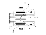
図3には本発明の正参照極及び負参照極の位置の一例を説明する図面であり、図4は図3においてA部、B部を矢印方向から見た正参照極及び負参照極の位置の一例を説明する図面である。図4(a)及び図(b)中の破線Yで囲った部分がセパレータ5の背面に正極及び負極が存在する範囲である。本発明では、正参照極は正極面上の近傍に、負参照極は負極面上の近傍に配置することにより、各参照極の位置決めを容易に行うことができる。ここで、正参照極3及び負参照極4は、全部が各々正極面上、負極面上にあるように図示されているが、正参照極3及び負参照極4の一部が各々正極面上、負極面上にあってもよい。図3、図4中の破線Xは、正極あるいは負極の電極端面を表しており、正参照極3及び負参照極4の全部が図3、図4に示すように正極あるいは負極の電極端面より内側に配置することがより好ましく、更に、正参照極3及び負参照極4は、正極と負極間の垂直線上に並ばないように配置することが好ましく、この場合、例えば、背景技術に記載の休止法抵抗の「オーム成分」の測定精度をより高めることが可能である。
FIG. 3 is a diagram for explaining an example of the positions of the positive reference electrode and the negative reference electrode of the present invention. FIG. 4 is a diagram of the positive reference electrode and the negative reference electrode viewed from the direction of the arrow A and B in FIG. It is drawing explaining an example of a position. A portion surrounded by a broken line Y in FIGS. 4A and 4B is a range where the positive electrode and the negative electrode exist on the back surface of the
図5は正極と正極面上に配置された正参照極3との距離(d1)及び負極と負極面上に配置された負参照極4との距離(d2)を説明する図であるが、d1、d2は各々正極面(セパレータ5側の電極面)と正参照極の最短距離、負極面(セパレータ5側の電極面)と負参照極の最短距離である。ここで、d1は正参照極3の幅(W)以上、d2は負参照極4の幅(W)以上であり、好ましくは2W以上、更に好ましくは3W以上である。その上限は特には限定しないが10W以下であり、これを超える場合、電気化学セルの内部抵抗が大きくなり、抵抗測定が難しくなる場合がある。また、d1、d2が各参照極の幅未満の場合には、その位置決めが困難になると伴に、各参照極が正負極間の充放電反応を阻害することも生じ易く、例えば、背景技術に記載の休止法抵抗の測定を精度良く実施することが難しくなる。
FIG. 5 is a diagram for explaining the distance (d1) between the positive electrode and the
図6は正参照極3、負参照極4の寸法を説明する図である。本発明において正参照極3、負参照極4の形状は特に限定されるものではなく、図6(a)では直方体、図6(b)では円柱を記載し説明するが、通常不定形であり、略直方体、略円柱等様々な形状をとる。正参照極及び負参照極の幅(W)は図6に示すとおりであるが、円柱の場合は直径、不定形の場合のWは各参照極の幅方向の距離の最大値である。本発明において、正参照極及び負参照極の幅(W)は0.15mm以下、好ましくは0.1mm以下、更に好ましくは0.08mm以下であり、参照極製作可能な幅以上であればよい。本発明の参照極の幅は特許文献1に記載されている幅(1mm)に比べ、極度に小さいが、正極面上の近傍あるいは負極面上の近傍に配置する為には、このレベルの幅が必要となる。その理由として、正参照極及び負参照極の幅(W)が上限を超える場合、d1、d2をW以上に大きくとる必要があることから、電気化学セル全体の内部抵抗が大きくなり抵抗測定が難しくなる。また、各参照極が正負極間の充放電反応を阻害することも生じ易く、例えば、背景技術に記載の休止法抵抗の測定を精度良く実施することも難しくなる。また、キャパシタ等の抵抗の小さいデバイスほど、正参照極及び負参照極の幅(W)を小さくする必要があり、例えば、Wが0.05mm以下にすることが必要となることがある。
FIG. 6 is a diagram for explaining the dimensions of the
正参照極及び負参照極の厚み(H)は図6に示すとおりであるが、円柱の場合は直径、不定形の場合のWは各参照極の厚み方向の距離の最大値である。本発明において、正参照極及び負参照極の厚み(H)は特に限定するものではなく、正負極の距離等により適宜決定することができるが、0.15mm以下が好ましく、0.1mm以下であれば更に好ましく、参照極の厚み(H)も製作可能であれば、できるだけ薄い方が好ましい。正参照極及び負参照極の厚み(H)がこの範囲にある場合、特に、電解液(セパレータ)の抵抗の分離精度を更に向上することが可能である。 The thicknesses (H) of the positive reference electrode and the negative reference electrode are as shown in FIG. 6, but in the case of a cylinder, W is the maximum value of the distance in the thickness direction of each reference electrode. In the present invention, the thickness (H) of the positive reference electrode and the negative reference electrode is not particularly limited, and can be appropriately determined depending on the distance between the positive electrode and the negative electrode, but is preferably 0.15 mm or less, and 0.1 mm or less. If the thickness (H) of the reference electrode can be manufactured, it is preferable that it is as thin as possible. When the thickness (H) of the positive reference electrode and the negative reference electrode is within this range, it is possible to further improve the separation accuracy of the resistance of the electrolytic solution (separator).
正参照極及び負参照極の長さ(L)は図6に示すとおりであるが、不定形の場合のWは各参照極の長さ方向の距離の最大値である。本発明において、正参照極及び負参照極の長さ(L)は特に限定するものではなく、正負極のサイズ等により適宜決定することができるが、5mm以下が好ましく、3mm以下であれば更に好ましく、前記参照極の長さ(L)も製作可能であれば、できるだけ短い方が好ましい。正参照極及び負参照極の長さ(L)がこの範囲にある場合、例えば、背景技術に記載の休止法抵抗における「平衡成分」の測定精度を更に向上することが可能である。 The lengths (L) of the positive reference electrode and the negative reference electrode are as shown in FIG. 6, but W in the case of an indefinite shape is the maximum value of the distance in the length direction of each reference electrode. In the present invention, the lengths (L) of the positive reference electrode and the negative reference electrode are not particularly limited and can be appropriately determined depending on the size of the positive electrode and the negative electrode, but are preferably 5 mm or less, and more preferably 3 mm or less. Preferably, the length (L) of the reference electrode is preferably as short as possible if it can be manufactured. When the length (L) of the positive reference electrode and the negative reference electrode is in this range, for example, it is possible to further improve the measurement accuracy of the “equilibrium component” in the pause method resistance described in the background art.
正参照極及び負参照極は上述の範囲であれば、各々の寸法やd1、d2の距離が異なっていても問題ないが、可能な限り同じサイズにすることが好ましい。 As long as the positive reference electrode and the negative reference electrode are in the above-mentioned range, there is no problem even if the dimensions and distances of d1 and d2 are different, but it is preferable to make them the same size as much as possible.
上述ごとく本発明における正参照極及び負参照極は、その寸法が小さいことから、その製作が困難な場合がある。このような場合、正参照極及び/あるいは負参照極が導電性基材上に、リチウム金属等の参照極材料を電気化学的に析出させて製作することが可能である。この方法を用いた場合、例えば、参照極の幅(W)が0.08mm以下、参照極の厚み(H)が0.05mm以下、参照極の長さ(L)が0.5mm以下の微細な形状の参照極を容易に製作することができる。例えば、厚さ0.03mmのステンレス板をエッチング加工等の微細加工で幅0.03mmにカットし、先端0.1mmを残し絶縁材料で被覆した導電性基材を準備し、その両面にリチウム金属を5μmの厚さで電気化学的に析出させて製作した参照極は、幅(W)が0.03mm、厚み(H)が0.04mm、長さ(L)が0.1mmと非常に微細なものである。 As described above, the positive reference electrode and the negative reference electrode in the present invention may be difficult to manufacture because of their small dimensions. In such a case, the positive reference electrode and / or the negative reference electrode can be manufactured by electrochemically depositing a reference electrode material such as lithium metal on the conductive substrate. When this method is used, for example, the reference electrode width (W) is 0.08 mm or less, the reference electrode thickness (H) is 0.05 mm or less, and the reference electrode length (L) is 0.5 mm or less. A reference electrode having a simple shape can be easily manufactured. For example, a stainless steel plate having a thickness of 0.03 mm is cut into a width of 0.03 mm by fine processing such as etching, and a conductive base material is prepared which is covered with an insulating material while leaving a tip of 0.1 mm. The reference electrode manufactured by electrochemically depositing 5 μm in thickness is 0.03 mm in width (W), 0.04 mm in thickness (H), and 0.1 mm in length (L). It is a thing.
本発明の電気化学セルは、特に適用範囲が限定されるものではないが、入出力特性、すなわち直流内部抵抗評価が重要とされるリチウムイオン電池、電気二重層キャパシタ、新型リチウム系蓄電デバイス、Ni水素電池等の蓄電デバイスに適用するとその効果は大きい。 The electrochemical cell of the present invention is not particularly limited in scope of application, but the input / output characteristics, that is, the DC internal resistance evaluation is important lithium ion battery, electric double layer capacitor, new lithium-based electricity storage device, Ni The effect is great when applied to an electricity storage device such as a hydrogen battery.
以下に実施例を示し、本発明の特徴とするところをさらに明確化するが、本発明は実施例により何ら限定されるものではない。 EXAMPLES Examples will be shown below to further clarify the features of the present invention, but the present invention is not limited to the examples.
(実施例1)
正極はLiCoO2(平均粒径7.4μm)89重量部に導電材であるアセチレンブラック6重量部、バインダーとしてポリフッ化ビニリデン5重量部をN−メチルピロリドン中で混合し、アルミ箔上に塗布・乾燥する事により合剤層を成形し、プレスする事により得た。電極層の厚みは80μmであり、電極密度は2.93g/ccであった。電極の電気伝導度は1.8×10−2S/cmであった。負極は黒鉛化MCMB(平均粒径25μm)93重量部に導電材であるアセチレンブラック2重量部、バインダーとしてポリフッ化ビニリデン5重量部をN−メチルピロリドン中で混合し、銅箔上に塗布・乾燥する事により合剤層を成形し、プレスする事により得た。電極層の厚みは80μmであり、電極密度は1.45g/ccであった。電極の電気伝導度は1.5×10−1S/cmであった。
Example 1
The positive electrode was mixed with 89 parts by weight of LiCoO 2 (average particle size: 7.4 μm), 6 parts by weight of acetylene black as a conductive material, and 5 parts by weight of polyvinylidene fluoride as a binder in N-methylpyrrolidone. The mixture layer was formed by drying and obtained by pressing. The thickness of the electrode layer was 80 μm, and the electrode density was 2.93 g / cc. The electrical conductivity of the electrode was 1.8 × 10 −2 S / cm. For the negative electrode, 93 parts by weight of graphitized MCMB (average particle size 25 μm), 2 parts by weight of acetylene black as a conductive material, and 5 parts by weight of polyvinylidene fluoride as a binder are mixed in N-methylpyrrolidone, and coated on copper foil and dried. This was obtained by molding and pressing the mixture layer. The thickness of the electrode layer was 80 μm, and the electrode density was 1.45 g / cc. The electric conductivity of the electrode was 1.5 × 10 −1 S / cm.
図1に示す構造の四極セルを試作した。正極に上記コバルト酸リチウム電極,正極に上記黒鉛電極を用い、電解液としては1モル濃度のLiPF6−3EC/7MEC(6フッ化リン酸リチウムをエチレンカーボネート/メチルエチルカーボネート〔重量比で3:7混合〕に溶解)であり,セパレータ5にはガラス繊維の不織布(厚み190μm,気孔率90%)を8枚用いている。正極層1、負極層2のサイズは14mm×20mmであり、図4に示すように正極集電体1’及び負極集電体2’は外部端子として電極層を形成しない部分を設けてある。また、正極層1、負極層2、セパレータ5には電解液が含浸されている。
A quadrupole cell having the structure shown in FIG. The lithium cobalt oxide electrode in a positive electrode, using the graphite electrode to the positive electrode, with LiPF 6 -3EC / 7MEC (6 hexafluorophosphate lithium ethylene carbonate / methyl ethyl carbonate [weight ratio of 1 molar concentration as the electrolyte solution 3: The
正参照極3、負参照極4は線径0.06mmのステンレス線に厚さ30μmのリチウムを両面から圧着したのち幅方向、長さ方向にカットすることにより、幅(W)を0.1mm、厚み(H)を0.12mm、長さ(L)は2mmとした。正参照極3は正極面上の近傍に、負参照極4は負極面上の近傍に図2の如く、上記セパレータ1枚を介して配置されており、正極と正極面上に配置された正参照極との距離(d1)及び負極と負極面上に配置された負参照極との距離(d2)は0.19mmである。このように正極と正参照極との距離(d1)及び負極と負参照極との距離(d2)は、セパレータをスペーサーとして参照極を配置するので、より容易にかつ精度良く決めることができる。正参照極3及び負参照極4の全部は図4及び図5に示すように正極、負極の各々の電極端面より0.1mm内側に配置した。
The
得られた電気化学セルを、非特許文献1に記載の電流休止法を用いて測定した。測定条件は4.5mAの電流を12分間印加/60秒休止するサイクルを、充電過程は放電末よりセル電圧(正極−負極間電圧)が4.2Vに達するまで、放電過程はセル電圧が2.5Vに達するまで実施した。この時、正極−負極間電圧(P−Nと記載する)、正極−正参照極電位(P−RPと記載する)、負極−負参照極電位(N−RNと記載する)を計測した。電圧計測には、参照極の消耗を防ぐために入力抵抗10MΩ以上の計測機を用いるのが好ましく、本実施例では入力抵抗10GΩのエレクトロメータを使用した。
The obtained electrochemical cell was measured using the current pause method described in
休止法抵抗は休止時の電圧変化から、休止直前の電圧と60秒休止後の電圧差を印加電流である4.5mAで割ることによりを求めた。また、非特許文献1に記載されているとおり、0から1秒までの電圧変化から算出される抵抗(休止法抵抗のオーム成分と呼ぶ)、1秒から60秒までの電圧変化から算出される抵抗(休止法抵抗の平衡成分と呼ぶ)についても同様に計算した。
The resting resistance was obtained by dividing the voltage difference immediately before resting from the voltage immediately before resting and the voltage difference after resting for 60 seconds by the applied current of 4.5 mA. Further, as described in
図7に充電過程、放電過程の電圧カーブを示す。このセルの放電容量は7.3mAhであった。図7には3本の充電あるいは放電カーブがある。2.5V〜4.2V間の電圧カーブは正極−負極間電圧(P−N)であり、その上にある4V近辺の電圧カーブが正極−正参照極間電位(P−RP)電位、0V〜1V間の電圧カーブは負極−負参照極間電位(N−RN)である。図中、各カーブにおける角上の部分が休止点である。以下、放電第1休止点の結果を用いて本発明を説明する。 FIG. 7 shows voltage curves of the charging process and discharging process. The discharge capacity of this cell was 7.3 mAh. In FIG. 7, there are three charge or discharge curves. The voltage curve between 2.5V and 4.2V is the voltage between the positive electrode and the negative electrode (PN), and the voltage curve near 4V above it is the potential between the positive electrode and the positive reference electrode (P-RP), 0V The voltage curve between ˜1V is the negative electrode-negative reference electrode potential (N-RN). In the figure, the portion on the corner of each curve is the rest point. Hereinafter, the present invention will be described using the result of the first discharge rest point.
図8に放電第1休止点(図7中B点)の拡大図を示す。P−Nの休止時の電圧変化(図8a)の休止直前の電圧と60秒休止後の電圧差を印加電流である4.5mAで割ることにより、セル休止法抵抗を求めた。セル休止法抵抗は17.0Ωであった。また、0から1秒までの電圧変化から算出される抵抗(休止法抵抗のオーム成分)、1秒から60秒までの電圧変化から算出される抵抗(休止法抵抗の平衡成分)についても同様に計算した。セルの休止法抵抗のオーム成分は12.5Ω、平衡成分は4.5Ωである。非特許文献1によれば、P−RPの休止時の電圧変化(図8b)から正極休止法抵抗、N−RNの休止時の電圧変化(図8c)から負極休止法抵抗を分離できることが示されている。これに従い、セル休止法抵抗と同様に計算し、正極休止法抵抗、負極休止法抵抗を算出した。正極休止法抵抗は4.2Ω、そのオーム成分は2.7Ω、平衡成分は1.5Ω、負極休止法抵抗は7.7Ω、オーム成分は4.4Ω、平衡成分は3.3Ωであった。
FIG. 8 shows an enlarged view of the first discharge rest point (point B in FIG. 7). The cell pause method resistance was obtained by dividing the voltage change immediately before the pause of the voltage change during the pause of PN (FIG. 8a) and the voltage difference after the 60 second pause by the applied current of 4.5 mA. The cell pause method resistance was 17.0Ω. The same applies to the resistance calculated from the voltage change from 0 to 1 second (ohmic component of the pause method resistance) and the resistance calculated from the voltage change from 1 second to 60 seconds (the equilibrium component of the pause method resistance). Calculated. The ohmic component of the quiescent resistance of the cell is 12.5Ω and the equilibrium component is 4.5Ω. According to
また、セル休止法抵抗と、分離した正極休止法抵抗、負極休止法抵抗の差分からセパレータ(電解液を含む)抵抗(図2中における正参照極3と負参照極4にあるセパレータ6枚分の抵抗)を求めた。セル休止法抵抗(17.0Ω)から正極休止法抵抗(4.2Ω)と負極休止法抵抗(7.7Ω)を引くと5.1Ωであり、これがセパレータ6枚分の休止法抵抗であることから、セパレータ(電解液を含む)1枚あたり0.9Ωである。また、正極休止法抵抗、負極休止法抵抗には各々セパレータ(電解液を含む)1枚分の抵抗が含まれることから、上記値からセパレータ(電解液を含む)1枚を引くことにより精度良く正極抵抗、負極抵抗を分離可能である。
Further, the separator (including the electrolyte) resistance (including 6 separators in the
上記実施例の如く、本発明の電気化学セルを用いることにより正極、負極、電解液(セパレータ)の各抵抗を精度良く同時に分離可能である。 Like the said Example, each resistance of a positive electrode, a negative electrode, and electrolyte solution (separator) is separable simultaneously with sufficient precision by using the electrochemical cell of this invention.
(実施例2)
実施例1において参照極を次のように変更する以外は実施例1と同様に四極セルを試作した。正参照極3、負参照極4は幅0.03mm、厚さ0.03mmのステンレス板にその両面からリチウムをセル内で電気化学的に析出させることにより得た。参照極の長さは、リチウムを電析させる部分以外は変性ポリエチレンフィルムによりマスクすることにより決めた。正参照極3、負参照極4は伴に幅(W)を0.03mm、厚み(H)を0.04mm、長さ(L)は0.2mmとした。正参照極3は正極面上の近傍に、負参照極4は負極面上の近傍に図2の如く、上記セパレータ1枚を介して配置されており、正極と正極面上に配置された正参照極との距離(d1)及び負極と負極面上に配置された負参照極との距離(d2)は0.19mmである。正参照極3及び負参照極4の全部は図4及び図5に示すように正極、負極の各々の電極端面より0.1mm内側に配置した。
(Example 2)
A quadrupole cell was prototyped in the same manner as in Example 1 except that the reference electrode in Example 1 was changed as follows. The
実施例1と同様に電流休止法で抵抗を評価した。セル休止法抵抗は17.3Ω、セルの休止法抵抗のオーム成分は12.4Ω、平衡成分は4.9Ωとなり、正極休止法抵抗は4.4Ω、そのオーム成分は2.8Ω、平衡成分は1.6Ω、負極休止法抵抗は7.5Ω、オーム成分は4.1Ω、平衡成分は3.4Ωであり、セパレータ(電解液を含む)抵抗は1枚あたり0.9Ωであった。実施例1と同様の結果が得られた。 The resistance was evaluated by the current pause method as in Example 1. The cell pause method resistance is 17.3Ω, the ohmic component of the cell pause method resistance is 12.4Ω, the equilibrium component is 4.9Ω, the positive electrode pause method resistance is 4.4Ω, the ohmic component is 2.8Ω, and the equilibrium component is The resistance of the negative electrode resting method was 7.5Ω, the ohmic component was 4.1Ω, the equilibrium component was 3.4Ω, and the separator (including electrolyte) resistance was 0.9Ω. The same result as in Example 1 was obtained.
(比較例1)
実施例1において参照極を次のように変更する以外は実施例1と同様に四極セルを試作した。正参照極3、負参照極4は線径0.06mmのステンレス線に厚さ50μmのリチウムを両面から圧着した後、幅方向、長さ方向にカットすることにより、幅(W)を0.2mm、厚み(H)を0.16mm、長さ(L)は2mmとした。正参照極3は正極面上の近傍に、負参照極4は負極面上の近傍に図2の如く、上記セパレータ1枚を介して配置されており、正極と正極面上に配置された正参照極との距離(d1)及び負極と負極面上に配置された負参照極との距離(d2)は0.19mmである。正参照極3及び負参照極4の全部は図4及び図5に示すように正極、負極の各々の電極端面より0.1mm内側に配置した。
(Comparative Example 1)
A quadrupole cell was prototyped in the same manner as in Example 1 except that the reference electrode in Example 1 was changed as follows. The
実施例1と同様に電流休止法で抵抗を評価した。セル休止法抵抗は17.7Ω、セルの休止法抵抗のオーム成分は12.9Ω、平衡成分は4.8Ωとなり、実施例1、実施例2と同様の結果が得られた。しかし、分離した正極休止法抵抗は5.1Ω、そのオーム成分は2.9Ω、平衡成分は2.2Ω、負極休止法抵抗は6.7Ω、オーム成分は4.1Ω、平衡成分は2.6Ωであった。また、セパレータ(電解液を含む)抵抗は1枚あたり1.0Ωであった。分離した平衡成分が、特に、実施例1、実施例2の値に対しずれる結果となった。このように正参照極3、負参照極4の幅(W)が0.15mm以上で、正極と正極面上に配置された正参照極との距離(d1)及び負極と負極面上に配置された負参照極との距離(d2)はW以下の場合、正極、負極、電解液(セパレータ)の各抵抗を精度良く同時に分離することが難しくなる。
The resistance was evaluated by the current pause method as in Example 1. The cell pause method resistance was 17.7Ω, the ohmic component of the cell pause method resistance was 12.9Ω, and the equilibrium component was 4.8Ω, and the same results as in Example 1 and Example 2 were obtained. However, the separated positive electrode pause method resistance is 5.1Ω, its ohmic component is 2.9Ω, the equilibrium component is 2.2Ω, the negative electrode pause method resistance is 6.7Ω, the ohmic component is 4.1Ω, and the equilibrium component is 2.6Ω. Met. Further, the resistance of the separator (including the electrolytic solution) was 1.0Ω per sheet. In particular, the separated equilibrium components were shifted from the values of Example 1 and Example 2. Thus, the width (W) of the
ハイブリッド電気自動車、瞬時停電バックアップ等の大電流負荷用途に向けた、最先端蓄電デバイスであるリチウムイオン電池、リチウムイオンキャパシタ、電気二重層キャパシタ等の内部抵抗に関し、正極、負極、電解液(セパレータ)の各抵抗を簡便にかつ精度良く同時に分離可能な電気化学セルを提供する。本発明の電気化学セルを用いることにより、大電流負荷用途蓄電デバイスにおいて重要な抵抗をより詳細に解析できると伴に、正極、負極、電解液(セパレータ)の各抵抗を基準とした新たな充放電制御等も可能となる。 For internal resistance of lithium-ion batteries, lithium-ion capacitors, electric double-layer capacitors, etc., which are state-of-the-art storage devices, for high-current load applications such as hybrid electric vehicles and momentary power outages It is possible to provide an electrochemical cell capable of easily and accurately simultaneously separating the resistors. By using the electrochemical cell of the present invention, it is possible to analyze in more detail important resistances in an electricity storage device for large current loads, and at the same time, new charges based on the resistances of the positive electrode, negative electrode, and electrolyte (separator) are used. Discharge control and the like are also possible.
1 正極層
1’ 正極集電体
2 負極層
2’ 負極集電体
3 正参照極
3’ 正参照極リード
4 負参照極
4’ 負参照極リード
5 セパレータ(電解液を含む)
11 ケース
1
11 cases
Claims (5)
5. The electrochemical cell according to claim 1, wherein the positive reference electrode and / or the negative reference electrode is obtained by electrochemically depositing a reference electrode material on a conductive substrate. An electrochemical cell according to claim 1.
Priority Applications (1)
| Application Number | Priority Date | Filing Date | Title |
|---|---|---|---|
| JP2009003325A JP5289983B2 (en) | 2009-01-09 | 2009-01-09 | Electrochemical cell |
Applications Claiming Priority (1)
| Application Number | Priority Date | Filing Date | Title |
|---|---|---|---|
| JP2009003325A JP5289983B2 (en) | 2009-01-09 | 2009-01-09 | Electrochemical cell |
Publications (2)
| Publication Number | Publication Date |
|---|---|
| JP2010161001A JP2010161001A (en) | 2010-07-22 |
| JP5289983B2 true JP5289983B2 (en) | 2013-09-11 |
Family
ID=42578025
Family Applications (1)
| Application Number | Title | Priority Date | Filing Date |
|---|---|---|---|
| JP2009003325A Active JP5289983B2 (en) | 2009-01-09 | 2009-01-09 | Electrochemical cell |
Country Status (1)
| Country | Link |
|---|---|
| JP (1) | JP5289983B2 (en) |
Families Citing this family (6)
| Publication number | Priority date | Publication date | Assignee | Title |
|---|---|---|---|---|
| JP5594583B2 (en) * | 2010-07-30 | 2014-09-24 | 独立行政法人産業技術総合研究所 | Method for manufacturing reference electrode |
| JP5442563B2 (en) * | 2010-08-26 | 2014-03-12 | ダイハツ工業株式会社 | Electrochemical cell |
| JP5955721B2 (en) * | 2012-02-14 | 2016-07-20 | 株式会社日本自動車部品総合研究所 | Lithium ion secondary battery and manufacturing method thereof |
| WO2015049778A1 (en) * | 2013-10-04 | 2015-04-09 | 株式会社日立製作所 | Lithium ion secondary battery, lithium ion secondary battery system, method for detecting potential in lithium ion secondary battery, and method for controlling lithium ion secondary battery |
| JP2015191878A (en) * | 2014-03-31 | 2015-11-02 | 株式会社日立製作所 | Lithium ion secondary battery system and method for diagnosing state of lithium ion secondary battery |
| JP6507679B2 (en) * | 2015-01-29 | 2019-05-08 | 日産自動車株式会社 | Lithium ion secondary battery |
Family Cites Families (4)
| Publication number | Priority date | Publication date | Assignee | Title |
|---|---|---|---|---|
| JP4365625B2 (en) * | 2003-06-25 | 2009-11-18 | 株式会社Kri | Electrochemical cell |
| JP2006179329A (en) * | 2004-12-22 | 2006-07-06 | Toyota Motor Corp | Electrochemical cell, evaluation device of electrochemical cell, evaluation method of electrochemical cell, and control method of electrochemical cell |
| JP2007193986A (en) * | 2006-01-17 | 2007-08-02 | Nissan Motor Co Ltd | Nonaqueous electrolyte secondary battery and its using method |
| JP2010086873A (en) * | 2008-10-01 | 2010-04-15 | Nissan Motor Co Ltd | Battery, and method and device for estimating electrode potential of battery |
-
2009
- 2009-01-09 JP JP2009003325A patent/JP5289983B2/en active Active
Also Published As
| Publication number | Publication date |
|---|---|
| JP2010161001A (en) | 2010-07-22 |
Similar Documents
| Publication | Publication Date | Title |
|---|---|---|
| US12027690B2 (en) | Pulse plating of lithium material in electrochemical devices | |
| Richter et al. | Thermal conductivity and internal temperature profiles of Li-ion secondary batteries | |
| CN111009679A (en) | Three-electrode battery cell, three-electrode soft package battery and preparation method thereof | |
| US8917095B2 (en) | Vehicle system and method for detecting hydrogen sulfide | |
| JP5289983B2 (en) | Electrochemical cell | |
| CN110828886A (en) | Three-electrode lithium ion battery and preparation method thereof | |
| KR101359902B1 (en) | Jig for Charging and Discharging of Battery Cell | |
| JP6337233B2 (en) | Battery evaluation method and battery characteristic evaluation apparatus | |
| CN114402473B (en) | All-solid-state lithium ion secondary battery system and charging device for all-solid-state lithium ion secondary battery | |
| CN101227015A (en) | Cylinder type lithium ion battery with high power rate and high safety performance | |
| EP4064395A1 (en) | Inspection method and manufacturing method of battery pack | |
| JP2020165859A (en) | Impedance measuring device for secondary batteries, secondary battery state estimating device, secondary battery system, and charing device for secondary batteries | |
| CN113422115A (en) | Lithium ion battery cell, preparation method of lithium ion battery cell and lithium analysis detection method | |
| CN111129432A (en) | Novel reference electrode and three-electrode system for nondestructive testing of lithium ion battery industry and method | |
| JP2022163239A (en) | Battery assembly | |
| CN104953087B (en) | A kind of lithium battery and its cathode, battery core, cathode voltage monitoring method | |
| JP5323375B2 (en) | Voltage distribution evaluation method for power storage devices | |
| KR20100059505A (en) | High power electric energy storage device | |
| US20170279166A1 (en) | Lithium-Ion Cell | |
| KR20220156659A (en) | Current collectors, electrochemical devices and electronic devices including the current collectors | |
| CN108923084B (en) | Method for testing current distribution of polar plate of polar group | |
| KR20180014763A (en) | A method for determining an anode potential and / or a cathode potential in a battery cell | |
| CN115360447A (en) | Three-electrode lithium ion battery and quick charge test method thereof | |
| KR101101546B1 (en) | Electrochemical capacitor and method for manufacturing the same | |
| JP2015103437A (en) | Method for short circuit inspection on all-solid battery |
Legal Events
| Date | Code | Title | Description |
|---|---|---|---|
| A621 | Written request for application examination |
Free format text: JAPANESE INTERMEDIATE CODE: A621 Effective date: 20111212 |
|
| TRDD | Decision of grant or rejection written | ||
| A01 | Written decision to grant a patent or to grant a registration (utility model) |
Free format text: JAPANESE INTERMEDIATE CODE: A01 Effective date: 20130528 |
|
| A61 | First payment of annual fees (during grant procedure) |
Free format text: JAPANESE INTERMEDIATE CODE: A61 Effective date: 20130605 |
|
| R150 | Certificate of patent or registration of utility model |
Ref document number: 5289983 Country of ref document: JP Free format text: JAPANESE INTERMEDIATE CODE: R150 |
|
| R250 | Receipt of annual fees |
Free format text: JAPANESE INTERMEDIATE CODE: R250 |
|
| R250 | Receipt of annual fees |
Free format text: JAPANESE INTERMEDIATE CODE: R250 |
|
| R250 | Receipt of annual fees |
Free format text: JAPANESE INTERMEDIATE CODE: R250 |