JP5289924B2 - Fixing base material for equipment and panel having the same - Google Patents
Fixing base material for equipment and panel having the same Download PDFInfo
- Publication number
- JP5289924B2 JP5289924B2 JP2008319966A JP2008319966A JP5289924B2 JP 5289924 B2 JP5289924 B2 JP 5289924B2 JP 2008319966 A JP2008319966 A JP 2008319966A JP 2008319966 A JP2008319966 A JP 2008319966A JP 5289924 B2 JP5289924 B2 JP 5289924B2
- Authority
- JP
- Japan
- Prior art keywords
- base material
- base
- equipment
- panel
- fixing
- Prior art date
- Legal status (The legal status is an assumption and is not a legal conclusion. Google has not performed a legal analysis and makes no representation as to the accuracy of the status listed.)
- Expired - Fee Related
Links
Images


Description
本発明は、空間を仕切るためのパネルに、設備取付用下地材を取付けるための設備用下地材固定金物及びこれを備えたパネルに係り、特に、骨組みとなる骨格形成部材の表面に石膏ボード等の表面材が貼付される、ボード式のパネルに用いられる設備取付用下地材を取付けるための設備用下地材固定金物及びこれを備えたパネルに関するものである。 The present invention relates to a facility base material fixing hardware for mounting a facility mounting base material on a panel for partitioning a space and a panel including the same, and in particular, a gypsum board or the like on the surface of a skeleton forming member serving as a framework. It is related with the equipment base material fixed metal fitting for attaching the equipment mounting base material used for the board-type panel, and a panel provided with the same.
従来より、住宅建築において、室内に形成される各空間を仕切るために、骨組みとなる枠体に石膏ボード等の表面材が貼付されたボード形式のパネルが使用されてきた。
このようなパネルは、角材等により形成された骨組み(枠体)に、石膏ボード等の表面材を貼付することにより立設される。
また、必要であれば、断熱材等を骨組みにセットし、表裏面の石膏ボードでこの断熱材を挟持した状態で立設される。
このようなパネルの構造としては、様々なものが提案されている(例えば、特許文献1、特許文献2参照)。
Conventionally, in a residential building, in order to partition each space formed in a room, a board-type panel in which a surface material such as a gypsum board is pasted on a frame body serving as a framework has been used.
Such a panel is erected by attaching a surface material such as a gypsum board to a framework (frame body) formed of square materials or the like.
Further, if necessary, a heat insulating material or the like is set on the framework, and the heat insulating material is sandwiched between gypsum boards on the front and back surfaces and is erected.
Various panel structures have been proposed (see, for example,
特許文献1には、柱と柱との間に耐力壁として簡単に装着することができる木造住宅用内壁パネルが開示されている。
この内壁パネルは、例えば、上下方向に平行に設置される上枠部及び下枠板と、これらの間を架橋するように設置される中桟により骨組みが構成されており、これら上枠部、下枠板、中桟の片側(又は、両側)に壁板が貼付される。
また、特許文献2には、柱間に設置される下地パネルが開示されている。
この下地パネルは、柱又は間柱間に、これら柱又は間柱と直交する方向へ複数の補助梁を渡して格子状の骨組みを構成し、この骨組みの片面(又は、両面)に下地パネルを貼付することにより形成される。
このとき、柱又は間柱の位置がわかるように、位置を示すマーキングが施される。
This inner wall panel is composed of, for example, an upper frame portion and a lower frame plate that are installed in parallel in the vertical direction, and a middle frame that is installed so as to bridge between them, the upper frame portion, Wall plates are affixed to one side (or both sides) of the lower frame plate and middle rail.
This foundation panel forms a lattice-like framework by passing a plurality of auxiliary beams in a direction perpendicular to these columns or studs between columns or studs, and affixing the foundation panel to one side (or both sides) of this framework Is formed.
At this time, the marking which shows a position is given so that the position of a pillar or a stud may be known.
上記のように、上記特許文献1及び特許文献2に開示されたパネルは、骨組みとその骨組みの表面及び/又は片面に貼付される板材により構成されている。
このため、パネルとしての役割を果たすことは可能であるが、このようなパネルに住宅設備品(例えば、吊戸棚、洗面台用シンク、手摺、ハンガ等の壁面に設置される設備品)を取付けることは困難であった。
つまり、洗面台用シンク等のような重量の大きい設備品を、特許文献1、2に開示されたようなパネルに取付ける場合には、骨組みのある場所を選択せざるを得ず、取付け位置が制限されるとともに、既製品が使用できずに、コストが増加する等の問題があった。
また、骨組みのある場所を選択せざるを得ないため、特許文献2に示すように、マーキング等を行う手間が生じる。
As described above, the panels disclosed in
For this reason, it is possible to play a role as a panel, but housing equipment (for example, equipment installed on the wall surface of a hanging cabinet, sink for sink, handrail, hanger, etc.) is attached to such a panel. It was difficult.
In other words, when attaching a heavy equipment such as a sink for a sink to a panel as disclosed in
In addition, since it is necessary to select a place where a skeleton is present, as shown in
このために、設備取付用の下地材を使用することが考えられた。
この設備取付用の下地材は板材であり、平行に配設される2本の縦枠を架橋するように設置される。
しかし、この設備取付用の下地材を取付ける際には、受けとしての桟木を縦枠に沿って配置し、この受用の桟木に設備取付用の下地材を取付ける必要があった。また、桟木に切り欠きを形成し、この切り欠き部に設備取付用の下地材を固定する必要があった。
このような施工方法の場合には、受用の桟木を設置する手間が生じるという問題があった。また、切り欠きを形成するため、桟木の奥行きが必要であり、狭い場所に設置することが困難であるという問題があった。
更に、切り欠きを形成する際に、割れが生じるという問題があるとともに、必要な桟木が増加するという問題点もある。
For this reason, it was considered to use a base material for equipment installation.
The base material for mounting the equipment is a plate material, and is installed so as to bridge two vertical frames arranged in parallel.
However, when attaching the base material for mounting the equipment, it is necessary to arrange the pier as a receiver along the vertical frame and attach the base material for mounting the equipment to the pier. Moreover, it was necessary to form a notch in the pier and to fix a base material for equipment attachment to the notch.
In the case of such a construction method, there is a problem in that it takes time to install a receiving pier. Moreover, since the notch is formed, the depth of the pier is necessary, and there is a problem that it is difficult to install in a narrow place.
Furthermore, there is a problem that cracks occur when forming the notches, and there is also a problem that the required piers increase.
また、図13に示すように、断面が階段状に形成された金物を用いて、スタットに合板を固定する方法があるが、施工性が悪く、壁面に不陸が生じるという問題点があった。
つまり、図13(a)に示すように、両側に起立するスタットに金物を取り付け、この金物に下地材を取付けるという施工方法がとられるのであるが、下地材を取付ける際には、下地材が落下しないように作業員が下地材を支持しながら金物へ固定しなければならず、作業性が非常に悪い。
また、図13(b)に示すように、石膏ボード等の表面材を貼付した場合に、金物をスタットに固定する際に使用した締結材のために不陸が生じることとなり外観性が悪い。
更に、壁の両面に下地材を取付けたい場合には、金物が2個必要となり、コストの面でも不利である。
Moreover, as shown in FIG. 13, there is a method of fixing a plywood to a stat using a hardware whose cross section is formed in a step shape, but there is a problem that workability is poor and unevenness occurs on the wall surface. .
That is, as shown in FIG. 13 (a), a construction method is adopted in which a hardware is attached to a stat that stands on both sides, and a base material is attached to the hardware. The worker must fix the base material to the hardware while supporting the base material so as not to fall, and workability is very poor.
Moreover, as shown in FIG.13 (b), when surface materials, such as a gypsum board, are affixed, unevenness will arise for the fastening material used when fixing a hardware to a stat, and its external appearance property is bad.
Furthermore, when it is desired to attach the base material to both surfaces of the wall, two hardwares are required, which is disadvantageous in terms of cost.
本発明の目的は、上記各問題点を解決することにあり、住宅用設備品を取付けるための設備取付用下地材を、パネル内部の骨組みに簡易に配設するための設備用下地材固定金物及びこれを備えたパネルを提供することにある。 An object of the present invention is to solve the above-mentioned problems, and a base material for fixing a base material for equipment for easily disposing a base material for mounting equipment for mounting a housing equipment on a framework inside the panel. And providing a panel having the same.
上記課題は、請求項1に係る発明によれば、空間を仕切るためのパネルに埋設され、前記パネル外部に備品を取付けるための下地となる設備取付用下地材を取付けるための金物であって、略矩形平板状の支持部と、該支持部の相対向する二辺より各々立ち下がる骨格部材挟持部と、前記支持部の相対向する前記二辺より、前記枠挟持部が立ち下がる方向と反対方向へ立ち上がる下地固定片と、を備え、前記支持部における前記下地固定片から前記設備取付用下地材の厚み分離隔した位置からは、前記下地固定片が立ち上がる方向と同方向へ向けて下地支持片が更に立ち上がっており、前記骨格部材挟持部で前記パネルの骨格となる骨格形成部材を挟持するとともに、前記設備取付用下地材を前記下地固定片と前記下地支持片とで挟持された状態で固定することにより、前記パネルを構成する前記骨格形成部材に前記設備取付用下地材が取付けられることにより解決される。
According to the invention according to
このように、本発明に係る設備用下地材固定金物によれば、骨格部材挟持部を骨格形成部材に固定し、下地固定片によって設備取付用下地材を支持できる。
このため、設備用下地材固定金物を介して、簡易に設備取付用下地材を骨格形成部材に取付けることができる。
よって、従来のように受けとしての桟木が不要となるとともに、桟木に切り欠きを形成し、この切り欠き部に設備取付用の下地材を固定する手間を省略することができる。
また、切り欠きを形成するための桟木の奥行きを考慮する必要がないため、施工場所の制限がなくなる。
更に、桟木に切り欠きを形成する必要がないため、この際に、割れが生じるという問題もなくなるとともに、必要な桟木が増加するという問題もなくなり、コスト面においても有利である。
このため、設備用下地材固定金物の位置決めが容易になり、施工効率が向上する。
また、支持部の相対向する二辺より下地固定片が各々立ち上がっているため、表裏2枚の設備取付用下地材を、一つの設備用下地材固定金物により固定することができる。
このため、作業性及びコスト面においてもまた有利なものとなる。
なお、骨格形成部材とは、パネルの骨格を構成する縦枠、横枠、補強材等の部材を全般的に指す。
なので、本発明に係る設備用下地材固定金物は、縦枠、横枠等、骨組みを形成する部材全てに取付けることが可能である。
また、パネルは、空間を仕切るためのものであればよく、部屋を区切る界壁、一般的に空間を仕切る間仕切り壁、天井を仕切る天井パネル等、どのような用途のパネルであってもよい。
更に、パネルとは、工場等により事前に組み立てられて出荷されるもの、現場にて組み立てられて使用されるもの双方を含む概念であり、特に製造形態や出荷形態等は問わない。
As described above, according to the equipment base material fixing hardware according to the present invention, the skeleton member sandwiching portion can be fixed to the skeleton forming member, and the equipment attachment base material can be supported by the base fixing piece.
For this reason, the base material for equipment attachment can be easily attached to the skeleton forming member via the base material fixing hardware for equipment.
As a result, it is not necessary to use a crosspiece as a receiver as in the prior art, and it is possible to eliminate the trouble of forming a notch in the crosspiece and fixing the base material for equipment installation to this cutout portion.
Moreover, since it is not necessary to consider the depth of the pier for forming the notch, there is no restriction on the construction site.
Furthermore, since it is not necessary to form a notch in the pier, there is no problem that cracking occurs at this time, and there is no problem that the required pier increases, which is advantageous in terms of cost.
For this reason, positioning of the base material fixed fixture for facilities becomes easy, and construction efficiency improves.
In addition, since the base fixing pieces rise from the two opposite sides of the support portion, the two front and back equipment mounting base materials can be fixed by one equipment base material fixing hardware.
For this reason, it is also advantageous in terms of workability and cost.
The skeleton forming member generally refers to members such as a vertical frame, a horizontal frame, and a reinforcing material that constitute the skeleton of the panel.
Therefore, the base material fixture for equipment according to the present invention can be attached to all members forming a framework such as a vertical frame and a horizontal frame.
Further, the panel may be a panel for partitioning a space, and may be a panel for any application such as a boundary wall for partitioning a room, a partition wall for partitioning a space, a ceiling panel for partitioning a ceiling.
Further, the panel is a concept including both those assembled and shipped in advance by a factory or the like, and those assembled and used in the field, and the manufacturing form and the shipping form are not particularly limited.
このとき、前記支持部からは、前記下地固定片が立ち上がる方向と同方向へ向けて下地支持片が立ち上がっており、前記下地支持片は、前記下地固定片から、前記設備取付用下地材の厚み分離隔した位置に形成され、前記設備取付用下地材は、前記下地固定片と前記下地支持片とで挟持された状態で固定されるよう構成されていると好適である。 At this time, from the support portion, the base support piece stands up in the same direction as the direction in which the base fixing piece rises, and the base support piece extends from the base fixing piece to the thickness of the equipment mounting base material. It is preferable that the equipment mounting base material is formed at a separated position and is fixed in a state of being sandwiched between the base fixing piece and the base support piece.
このように構成されていると、下地固定片と下地支持片とで、設備取付用下地材を挟持することができる。
つまり、この下地固定片と下地支持片とで設備取付用下地材を挟持して仮り留めすることができるため、下地固定片に設備取付用下地材を締結部材で固定する際に、作業員の作業が容易になり、作業性が向上する。
If comprised in this way, the base material for equipment attachment can be clamped with the base fixing piece and the base support piece.
That is, since the base material for equipment installation can be sandwiched and temporarily fixed by the base fixing piece and the base support piece, when fixing the base material for equipment installation to the base fixing piece with the fastening member, Work becomes easier and workability is improved.
また、このとき、前記骨格部材挟持部は、前記支持部から鋭角を成して立ち下がるとともに、前記下地固定片は、前記支持部から鈍角を成して立ち上がるよう構成されていると好適である。 Further, at this time, it is preferable that the skeleton member sandwiching portion is configured to fall at an acute angle from the support portion, and the base fixing piece is configured to rise at an obtuse angle from the support portion. .
つまり、本発明においては、骨格部材挟持部及び下地固定片は、支持部に対して傾斜して起立していることとなる。
具体的には、骨格部材挟持部と支持部との成す角は鋭角に、下地固定片と支持部が成す角は鈍角となるとともに、両者の角度の和は約180°となるように構成されている。
換言すれば、骨格部材挟持部間の距離は、下地固定片間の距離よりも小さくなるように構成されている。
このため、下地固定片に対し、両者が近づく方向への力を加えると、骨格部材挟持部は両者が離隔する方向へ押し開かれる。
よって、下地固定片に対し力を加えて骨格部材挟持部を押し開き、この縦枠挟持部間に骨格形成部材を嵌入することが可能となる。
In other words, in the present invention, the skeleton member sandwiching portion and the base fixing piece stand upright with respect to the support portion.
Specifically, the angle formed between the frame member sandwiching portion and the support portion is an acute angle, the angle formed between the base fixing piece and the support portion is an obtuse angle, and the sum of both angles is configured to be about 180 °. ing.
In other words, the distance between the skeleton member sandwiching portions is configured to be smaller than the distance between the base fixing pieces.
For this reason, if the force to the direction which both approach is applied with respect to a base | substrate fixed piece, a frame member clamping part will be pushed open in the direction which both space apart.
Therefore, it is possible to push open the skeleton member holding portion by applying a force to the base fixing piece, and to insert the skeleton forming member between the vertical frame holding portions.
そして、このように骨格形成部材が骨格部材挟持部間に挟持された状態においては、骨格挟持部の復元力により、骨格形成部材は強固に把持されることとなる。
よって、骨格形成部材は、骨格部材挟持部間に確実に仮り留めされることとなり、作業者が下地材固定金物から手を離しても、下地材固定金物が骨格形成部材から外れたり、その位置がずれたりすることがない。
このため、作業性が向上する。
In this state where the skeleton forming member is sandwiched between the skeleton member sandwiching portions, the skeleton forming member is firmly held by the restoring force of the skeleton sandwiching portion.
Therefore, the skeleton forming member is surely temporarily secured between the skeleton member sandwiching portions, and even if the operator releases his hand from the base material fixing hardware, the base material fixing hardware may come off from the skeleton forming member, or the position thereof. Will not slip.
For this reason, workability | operativity improves.
更に、このとき、前記下地固定片には、前記下地支持片が配設される方向へ向けて屈曲した自由端部分を有する下地固定爪が形成されていると好適である。
このように構成されていると、下地固定片と下地支持片との間に、設備取付用下地材を挟持した際に、この下地固定爪を設備取付用下地材方向に向けて押圧して差し込むことにより、設備取付用下地材は、下地固定片により確実に仮り留めされることとなる。
このため、より作業性が向上する。
Further, at this time, it is preferable that a base fixing claw having a free end portion bent in a direction in which the base support piece is disposed is formed on the base fixing piece.
With this configuration, when the equipment mounting base material is sandwiched between the base fixing piece and the base support piece, the base fixing claws are pressed and inserted toward the equipment mounting base material. As a result, the base material for equipment installation is securely secured by the base fixing piece.
For this reason, workability | operativity improves more.
更に、本発明に係るパネルは、骨組みとなる骨格形成部材で形成された略矩形状の枠体と、住宅設備品を取付けるための下地となる設備取付用下地材と、請求項1乃至請求項4いずれか一項記載の設備用下地材固定金物と、を少なくとも備え、前記設備用下地材固定金物を介して前記設備取付用下地材が前記骨格形成部材に取付けられている。
このように、本発明に係るパネルは、設備取付用下地材が配設された骨組みを有して構成されているため、洗面台用シンク等の設備品を簡易に取付けることができる。
Furthermore, the panel according to the present invention includes a substantially rectangular frame formed of a skeleton forming member that is a framework, a facility mounting base material that serves as a base for mounting housing equipment, and claims 1 to 10. 4. The equipment base material fixed hardware according to
Thus, since the panel which concerns on this invention has a frame | skeleton with which the base material for equipment attachment was arrange | positioned, equipments, such as a sink for sinks, can be attached easily.
本発明に係る設備用下地材固定金物によれば、骨格部材挟持部を骨格形成部材に固定し、下地固定片によって設備取付用下地材を支持できる。
このため、この設備用下地材固定金物を介して、簡易に設備取付用下地材を骨格形成部材に取付けることができる。
According to the equipment base material fixing hardware according to the present invention, the skeleton member clamping portion can be fixed to the skeleton forming member, and the equipment attachment base material can be supported by the base fixing piece.
For this reason, the base material for equipment attachment can be easily attached to the skeleton forming member via the base material fixing fixture for equipment.
また、支持部の相対向する二辺より下地固定片が各々立ち上がっているため、表裏2枚の設備取付用下地材を、一つの下地材固定金物により固定することができ、作業性及びコスト面においてもまた有利である。 In addition, since the base fixing pieces rise from the two opposite sides of the support part, the two base materials for mounting the equipment on the front and back sides can be fixed with a single base material fixing hardware. Is also advantageous.
更に、本発明に係る設備用下地材固定金物によれば、下地固定片と下地支持片とによって設備取付用下地材を挟持できる。
つまり、下地固定片と下地支持片とによって、設備取付用下地材を仮り留めすることができる。
この状態で、締結材による本固定を行えば、設備用下地材固定金物を介して、簡易に設備取付用下地材を取付けることができる。
このため、従来のように受けとしての桟木が不要となるとともに、桟木に切り欠きを形成し、この切り欠き部に設備取付用の下地を固定する手間を省略することができる。
Furthermore, according to the equipment base material fixing hardware according to the present invention, the equipment mounting base material can be sandwiched between the base fixing piece and the base support piece.
That is, the base material for equipment attachment can be temporarily secured by the base fixing piece and the base support piece.
In this state, if the main fixing with the fastening material is performed, the equipment mounting base material can be easily attached via the equipment base material fixing hardware.
This eliminates the need for a pedestal as a receiving member as in the prior art, and eliminates the need for forming a notch in the pedestal and fixing the base for mounting the equipment in the notched portion.
また、本発明においては、下地固定片には、下地固定爪が形成されている。
このため、より確実に、下地固定片と下地支持片とによって、設備取付用下地材を仮り留めすることができる。
In the present invention, the base fixing piece is formed with a base fixing claw.
For this reason, the base material for installation can be temporarily secured by the base fixing piece and the base support piece.
また、下地固定片には、締結部材貫通孔が形成されており、締結部材は、この締結部材貫通孔から螺設される。
このとき、締結部材として所謂ラッパ螺子を使用し、大きな力でこのラッパ螺子をねじ込むと、この押圧力により、このラッパ螺子の頭部は、締結部材貫通孔の周縁部を変形させながら押し込まれ、締結部材貫通孔内に格納される。
よって、この部分にて不陸が生じることを防止することができ、設備取付用下地材の表面に表面材を貼付した際の外観性が向上する。
In addition, a fastening member through hole is formed in the base fixing piece, and the fastening member is screwed from the fastening member through hole.
At this time, when using a so-called trumpet screw as a fastening member and screwing this trumpet screw with a large force, the head of this trumpet screw is pushed in by deforming the peripheral edge portion of the fastening member through hole by this pressing force, It is stored in the fastening member through hole.
Therefore, unevenness can be prevented from occurring in this portion, and the appearance when a surface material is pasted on the surface of the base material for installation is improved.
以下、本発明の一実施形態を図面に基づいて説明する。
なお、以下に説明する構成は本発明を限定するものでなく、本発明の趣旨の範囲内で種々改変することができるものである。
本実施形態は、住宅用設備品を取付けるための設備取付用下地材を、パネル内部の骨組みに簡易に配設するための設備用下地材固定金物(以下、単に「下地材固定金物」と記す)及びこれを備えたパネルに関するものである。
Hereinafter, an embodiment of the present invention will be described with reference to the drawings.
Note that the configuration described below does not limit the present invention and can be variously modified within the scope of the gist of the present invention.
In the present embodiment, equipment mounting base materials for mounting residential equipment are simply described as “base material fixing hardware” (hereinafter simply referred to as “base material fixing hardware”). ) And a panel having the same.
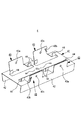
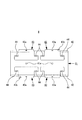
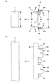
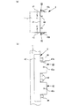
図1乃至図12は、本発明に係る一実施形態を示すものであり、図1は間仕切り壁を示す分解図、図2は下地材固定金物を示す斜視図、図3は下地材固定金物を示す上面図、図4は下地材固定金物を示す底面図、図5は下地材固定金物を示す側面図、図6乃至図10は設備取付用下地材の取付方法を示す説明図、図11は下地固定爪の係止状態を示す説明図、図12は設備取付用下地材の取付方法を示す説明図である。 1 to 12 show an embodiment according to the present invention. FIG. 1 is an exploded view showing a partition wall, FIG. 2 is a perspective view showing a base material fixing hardware, and FIG. 3 is a base material fixing hardware. FIG. 4 is a bottom view showing the base material fixing hardware, FIG. 5 is a side view showing the base material fixing hardware, FIGS. 6 to 10 are explanatory diagrams showing how to install the base material for equipment mounting, and FIG. FIG. 12 is an explanatory view showing a mounting state of the equipment mounting base material.
本実施形態においては、パネルとして間仕切り壁Sを例示し、下地材固定金物4,4を、縦枠1,1に取付ける例を説明する。
なお、パネルとしての間仕切り壁Sは、工場等により事前に組み立てられて出荷されるもの、現場にて組み立てられて使用されるもの双方を含む概念であり、本発明の趣旨を逸脱するものでなければ、特に製造形態や出荷形態等は問わない。
本実施形態においては、骨格形成部材として、縦枠1,1及び横枠2,2を備えるパネルとしての間仕切り壁Sが例示される。
まず、図1により本実施形態に係る間仕切り壁Sについて説明する。
本実施形態に係る間仕切り壁Sとは、住宅内部の室内空間を仕切る壁である。
なお、本実施形態においては、間仕切り壁Sの例を示したが、これに限られることはなく、天井等に使用されるパネルに適用されていてもよい。
図1に示すように、本実施形態に係る間仕切り壁Sは、骨組みS1、設備取付用下地材S2、表面材S3,S3、とで構成されている。
In this embodiment, the partition wall S is illustrated as a panel and the example which attaches the base material fixed
In addition, the partition wall S as a panel is a concept including both what is assembled and shipped in advance by a factory or the like, and what is assembled and used in the field, and must depart from the spirit of the present invention. In particular, the production form, the shipment form, etc. are not particularly limited.
In this embodiment, the partition wall S as a panel provided with the
First, the partition wall S according to the present embodiment will be described with reference to FIG.
The partition wall S which concerns on this embodiment is a wall which partitions the indoor space inside a house.
In addition, in this embodiment, although the example of the partition wall S was shown, it is not restricted to this, You may be applied to the panel used for a ceiling etc.
As shown in FIG. 1, the partition wall S which concerns on this embodiment is comprised by frame S1, the base material S2 for equipment attachment, and surface material S3, S3.
本実施形態に係る骨組みS1は、縦枠1,1、横枠2,2を有して構成されている。
横枠2,2は、略平行に配設されるとともに、その両端部から縦枠1,1が1本ずつ、横枠2,2間を架橋するように固定されている。
このとき、縦枠1,1と横枠2,2とは略直交しており、縦枠1,1及び横枠2,2により矩形状の枠体が形成され、これが骨組みS1となる。
The framework S1 according to the present embodiment is configured to have
The
At this time, the
また、本実施形態に係る設備取付用下地材S2は、略矩形状の平板である。
設備取付用下地材S2の長辺は、縦枠1,1間の距離より若干小さく形成されており、縦枠1,1間を架橋した状態に配設される。
この設備取付用下地材S2は、両短辺(長辺と直交する辺)側に取付けられる下地材固定金物4,4を介して、縦枠1,1に取付けられる。
この下地材固定金物4,4に関しては、後述する。
Further, the facility mounting base material S2 according to the present embodiment is a substantially rectangular flat plate.
The long side of the equipment mounting base material S2 is formed slightly smaller than the distance between the
This equipment mounting base material S2 is attached to the
The base
更に、本実施形態に係る表面材S3,S3は、略矩形状の平板であり、通常、板材、石膏ボード等で形成される。
表面材S3,S3は、設備取付用下地材S2が取付けられた骨組みS1を挟持した状態となるように、骨組みS1の両面に貼付される。
なお、この縦枠1,1及び横枠2,2の構成はこれに限られるものではなく、材質、形状等、施工現場及び施工条件に応じて適宜変更することができる。
Furthermore, the surface materials S3 and S3 according to the present embodiment are substantially rectangular flat plates and are usually formed of a plate material, a gypsum board, or the like.
The surface materials S3 and S3 are affixed to both sides of the framework S1 so as to sandwich the framework S1 to which the equipment mounting base material S2 is attached.
The configurations of the
図2乃至図5により、本実施形態に係る下地材固定金物4について説明する。
本実施形態に係る下地材固定金物4は、支持部41、2個の骨格部材挟持部としての縦枠挟持部42、4個の下地固定片43、8個の下地支持片44を有して構成されている。
なお、本実施形態に係る下地材固定金物4は、一の鋼板を打ち抜き処理及び屈曲処理することにより形成されている。
The base
The base
Note that the base
本実施形態に係る支持部41は、略長方形状の平板部分であり、その相対向する長辺からは、略長方形状の縦枠挟持部42,42が立ち下がっている。
つまり、支持部41及び縦枠挟持部42,42により、断面略コ字状を形成している。
また、縦枠挟持部42,42は、支持部41と鋭角を成して立ち下がっている。
換言すれば、縦枠挟持部42,42の自由端辺の距離は、支持部41の短辺の長さよりも小さくなっている。
The
That is, the
Further, the vertical
In other words, the distance between the free ends of the vertical
これは、縦枠挟持部42,42により縦枠1を挟持するためである。
つまり、この縦枠挟持部42,42を押し広げた状態で縦枠1を嵌入すれば、この縦枠挟持部42,42の復元力により、縦枠を強固に把持することができる。
なお、支持部41の略中央部には、締結材貫通孔41a,41aが、長辺と平行方向に並列して形成されている。
This is because the
That is, if the
Note that fastening material through
また、支持部41の両長辺からは、下地固定片43,43が各々立ち上がっている(縦枠挟持部42,42が起立する方向と逆の方向へ起立している)。
この下地固定片43は、支持部41の一の長辺から2個ずつ並列して立ち上がっている略矩形状の部分である。
また、下地固定片43は、支持部41と鈍角を成して立ち上がっている。
換言すれば、下地固定片43の自由端辺の距離は、支持部41の短辺の長さよりも大きくなっている。
In addition,
The
The
In other words, the distance of the free end side of the
更に、この下地固定片43の略中央部には、締結材貫通孔43aが形成されている。
この締結材貫通孔43aの径は、設備取付用下地材S2を固定するためのラッパ螺子Rを螺設するためのものである。
なお、ラッパ螺子Rを螺設する際、大きな力でこのラッパ螺子Rをねじ込むと、この押圧力により、このラッパ螺子の頭部は、締結部材貫通孔の周縁部を変形させながら押し込まれ、締結部材貫通孔43a内に格納される。
このため、ラッパ螺子Rを完全に螺子込んだ状態においては、このラッパ螺子Rの頭部が、この締結材貫通孔43aより突出することがなく、下地固定片43の外側面に不陸部分が形成されることを防止することができる。
Further, a fastening material through-
The diameter of the fastening material through
When the trumpet screw R is screwed, when the trumpet screw R is screwed with a large force, the head of the trumpet screw is pushed in by deforming the peripheral portion of the fastening member through-hole due to the pressing force, and is fastened. It is stored in the member through
For this reason, in the state where the trumpet screw R is completely screwed in, the head of the trumpet screw R does not protrude from the fastening material through-
なお、本実施形態においては、縦枠挟持部42と下地固定片43とは連続した一枚の板状部として形成されている。
このため、下地固定片43に力を加えると、縦枠挟持部42にもこの加えられた力が影響を及ぼし、その位置を変える。
具体的には、相対向する辺上に形成される下地固定片43,43に対し、互いに近接する方向へ向けて力を加えれば、互いに対向する辺から立ち下がる縦枠挟持部42,42は、互いに離隔する方向へと動く(つまり、縦枠挟持部42,42は、押し広げられた状態となる)。
In the present embodiment, the vertical
For this reason, when a force is applied to the
Specifically, when a force is applied toward the
また、支持部41の一の長辺から立ち上がる2個の下地固定片43,43の一方側には、下地固定爪43bが形成されている。
この下地固定爪43bは、下地固定片43の外側(隣接する支持固定片43から離隔する側)に形成される。
Further, a
The
また、この下地固定爪43bの自由端側は鋭利な状態に形成されるとともに、内側(下地支持片44が形成される側)に向かって屈曲している。
これは、設備取付用下地材S2が下地固定片43と下地支持片44とに挟持された際、設備取付用下地材S2を係止固定する役割を果たすためである。
Further, the free end side of the
This is because when the equipment mounting base material S2 is sandwiched between the
なお、本実施形態においては、下地固定爪43bは、支持部41に対して対角線方向に配置される下地固定片43,43に形成される。
ただし、下地固定爪43bの配設位置、配設数等はこれに限られることはなく、設備取付用下地材S2を係止することができれば、どのように設計されていてもよい。
In the present embodiment, the
However, the arrangement position, the number of arrangements, and the like of the
また、この下地固定片43の両端部には、下地支持片44,44が立ち上がっている。
この下地支持片44,44は、支持部41の内側(対向する長辺の方向側)に、設備取付用下地材S2の厚さ分の空隙をもって形成されている。
つまり、設備取付用下地材S2は、この下地固定片43,43と、下地支持片44,44,44,44との間に挟持されることとなる。
Further,
The
That is, the equipment mounting base material S2 is sandwiched between the
次いで、図6乃至図12により、下地材固定金物4の使用方法について説明する。
図6に示すように、下地材固定金物4を縦枠1の所定位置に取付ける。
なお、前述のとおり、縦枠挟持部42,42間の距離W2は、下地固定片43,43間W3よりも小さくなるように構成されている。
Next, a method of using the base
As shown in FIG. 6, the base
As described above, the distance W2 between the vertical
つまり、縦枠挟持部42及び下地固定片43は、支持部41に対して傾斜して起立している。具体的には、縦枠挟持部42と支持部41との成す角θ1は鋭角に、下地固定片43と支持部41が成す角θ2は鈍角となるとともに、θ1+θ2≒180°となるように構成されている。
In other words, the vertical
また、前述のとおり、縦枠挟持部42,42間の距離W2は、縦枠1の幅W1よりも小さくなるように構成されている。
更に、縦枠挟持部42と下地固定片43とは連続した一枚の板状部として形成されており、下地固定片43に力を加えると、縦枠挟持部42にもこの加えられた力が影響を及ぼし、その位置を変える。
このため、具体的には、図6(a)に示すように、下地固定片43,43に対しA方向の力を加えると、縦枠挟持部42,42はB方向へ押し開かれる。
Further, as described above, the distance W2 between the vertical
Further, the vertical
Therefore, specifically, as shown in FIG. 6A, when a force in the A direction is applied to the
このようにして、縦枠挟持部42,42が押し開かれた状態を図7に示す。
本実施形態においては、縦枠挟持部42,42が押し開かれた際の両者の距離W2´(つまり、縦枠挟持部42及び下地固定片43が、支持部41に対して略垂直に起立している状態での距離)は、縦枠1の幅W1とほぼ同一となるように構成されている。
このため、下地固定片43,43に対しA方向の力を加えて、縦枠挟持部42,42を押し開くと、この縦枠挟持部42,42間に縦枠1を嵌入することが可能となる。
FIG. 7 shows a state where the vertical
In the present embodiment, the distance W2 ′ between the vertical
For this reason, when a force in the A direction is applied to the
このようにして、下地材固定金物4が縦枠1に取付けられた様子を図8に示す。
図8(a)に示すように、下地材固定金物4は、縦枠挟持部42,42間に縦枠1を挟持することにより縦枠1に取付けられるが、このとき、縦枠挟持部42,42の復元力により、縦枠1はC方向の力を受けることとなる。
よって、縦枠1は、縦枠挟持部42,42に確実に仮り留めされることとなり、作業者が下地材固定金物4から手を離しても、下地材固定金物4が縦枠1から外れたり、その位置がずれたりすることがない。
このため、作業性が向上する。
FIG. 8 shows how the base
As shown in FIG. 8A, the base
Therefore, the
For this reason, workability | operativity improves.
また、締結部材Tは、縦枠1の内側を向く面(骨組みS1の内側方向を向く面)に取付けられるため、表面材S3が貼付される面に、締結部材Tの頭部が突出することがない。
このため、締結部材Tが、表面材S3を貼付する際に障害となることがなく(不陸を形成することがなく)、仕上がりの外観性が向上する。
更に、設備取付用下地材S2が、面外への引張力を受けても、固定金物4が縦枠1より引張力に滑り出るのを防止することができる。
Moreover, since the fastening member T is attached to the surface facing the inner side of the vertical frame 1 (the surface facing the inner side of the framework S1), the head of the fastening member T protrudes from the surface to which the surface material S3 is attached. There is no.
For this reason, the fastening member T does not become an obstacle when the surface material S3 is affixed (without forming unevenness), and the finished appearance is improved.
Furthermore, even if the equipment mounting base material S2 receives a tensile force out of the plane, the fixed
次いで、図9に示すように、支持部41の略中央部に形成された締結材貫通孔41a,41aより締結部材Tを螺子込み、下地材固定金物4を本固定する。
なお、前述したとおり、縦枠挟持部42,42の復元力により、下地材固定金物4は縦枠1に確実に仮り留めされているため、作業員は、下地材固定金物4から手を離した状態で、締結部材Tを螺子込むことができる。
よって、締結作業を簡易に行うことが可能となり、作業性が向上する。
Next, as shown in FIG. 9, the fastening member T is screwed into the fastening material through
As described above, since the base material fixed
Therefore, it is possible to easily perform the fastening operation, and the workability is improved.
次いで、図10に示すように、設備取付用下地材S2を取付ける。
本実施形態においては、2枚の設備取付用下地材S2を取付ける。
このとき、設備取付用下地材S2は、下地固定片43と下地支持片44との間に挿入されて固定される。
なお、図11に示すように、設備取付用下地材S2を下地固定片43と下地支持片44との間に挿入した後、下地固定爪43bを矢印方向(設備取付用下地材S2へ向かう方向)へ倒して、その自由端部分を設備取付用下地材S2に突き刺すことにより、設備取付用下地材S2を下地材固定金物4へと仮り留めする。
Next, as shown in FIG. 10, the equipment mounting base material S <b> 2 is attached.
In the present embodiment, two pieces of equipment mounting base material S2 are attached.
At this time, the equipment mounting base material S <b> 2 is inserted and fixed between the
As shown in FIG. 11, after the equipment mounting base material S2 is inserted between the
次いで、図12(a)に示すように、締結材貫通孔43aより、ラッパ螺子Rを螺子込むことにより、設備取付用下地材S2を下地材固定金物4に本固定する。
なお、このとき、下地固定爪43bの自由端部分を設備取付用下地材S2に突き刺すことにより、設備取付用下地材S2は下地材固定金物4へと仮り留めされているため、作業員は、設備取付用下地材S2から手を離した状態で、ラッパ螺子Rを螺子込むことができる。
よって、締結作業を簡易に行うことが可能となり、作業性が向上する。
Next, as shown in FIG. 12A, the tapping screw R is screwed into the fastening material through
At this time, the equipment mounting base material S2 is temporarily fastened to the base
Therefore, it is possible to easily perform the fastening operation, and the workability is improved.
また、前述したが、この締結材貫通孔43aにラッパ螺子Rを螺設する際には、大きな力でラッパ螺子Rをねじ込むとよい。
このように大きな力を加えることにより、ラッパ螺子R頭部による押圧力のため締結部材貫通孔43aの周縁部が変形して、ラッパ螺子Rがねじ込まれることとなる。
よって、ラッパ螺子Rを完全に螺子込んだ状態においては、このラッパ螺子Rの頭部がこの締結材貫通孔43aより突出することがなく、下地固定片43の外側面に不陸部分が形成されることを防止することができる。
よって、図12(b)に示すように、設備取付用下地材S2の表面に、表面材S3を障害なく貼付することができ、間仕切り壁Sの外観性が向上する。
As described above, when the trumpet screw R is screwed into the fastening material through
By applying such a large force, the peripheral portion of the fastening member through-
Therefore, when the trumpet screw R is completely screwed in, the head of the trumpet screw R does not protrude from the fastening material through
Therefore, as shown in FIG.12 (b), the surface material S3 can be affixed on the surface of the base material S2 for equipment attachment without an obstacle, and the external appearance property of the partition wall S improves.
以上のように、本実施形態に係る下地材固定金物4を使用することによって、縦枠1,1に設備取付用設備取付用下地材S2を簡易に取付けることができる。
このため、設備取付用下地材S2の施工が容易になるとともに、作業性が向上する。
また、本実施形態によれば、一つの下地材固定金物4により2枚の(表裏の)設備取付用下地材S2を縦枠1に取付けることができる。
As described above, by using the base
For this reason, the construction of the facility mounting base material S2 is facilitated and workability is improved.
Further, according to this embodiment, two (front and back) equipment mounting base materials S <b> 2 can be attached to the
1 縦枠
2 横枠
4 下地材固定付金物
41 支持部
41a,43a 締結材貫通孔
42 縦枠挟持部(骨格部材挟持部)
43 下地固定片
43b 下地固定爪
44 下地支持片
R ラッパ螺子
S 間仕切り壁(パネル)
S1骨組み
S2 設備取付用下地材
S3 表面材
T 締結部材
DESCRIPTION OF
43
S1 frame S2 Equipment mounting base material S3 Surface material T Fastening member
Claims (4)
略矩形平板状の支持部と、
該支持部の相対向する二辺より各々立ち下がり、前記パネルの骨格となる骨格形成部材を挟持して仮り留めされることが可能に構成された骨格部材挟持部と、
前記支持部の相対向する前記二辺より、前記枠挟持部が立ち下がる方向と反対方向へ向けて各々立ち上がる複数の下地固定片と、を備え、
前記支持部における前記下地固定片から前記設備取付用下地材の厚み分離隔した位置からは、前記下地固定片が立ち上がる方向と同方向へ向けて複数の下地支持片が更に立ち上がっており、
前記骨格部材挟持部で前記パネルの骨格となる骨格形成部材を挟持するとともに、前記設備取付用下地材を複数の前記下地固定片と複数の前記下地支持片とで挟持された状態で固定することにより、前記パネルを構成する前記骨格形成部材に前記設備取付用下地材が取付けられることを特徴とする設備用下地材固定金物。 It is embedded in a panel for partitioning space, and is a hardware for mounting a facility mounting base material that is a base for mounting equipment outside the panel,
A substantially rectangular flat plate-shaped support portion;
The respective falling from two sides facing each other of the support portion is Ri, and the frame member holding portions configured to can be temporarily fastened by sandwiching a framework forming member serving as the skeleton of the panel,
A plurality of base fixing pieces each rising in the opposite direction to the direction in which the frame holding portion falls from the two opposite sides of the support portion;
From the position where the thickness of the base material for equipment installation is separated from the base fixing piece in the support part, a plurality of base support pieces are further raised in the same direction as the direction in which the base fixing piece rises,
The skeleton forming member that becomes the skeleton of the panel is sandwiched by the skeleton member sandwiching portion, and the base material for equipment installation is fixed in a state of being sandwiched by the plurality of base fixing pieces and the plurality of base support pieces. By the above, the equipment mounting base material is attached to the skeleton forming member constituting the panel.
Priority Applications (1)
| Application Number | Priority Date | Filing Date | Title |
|---|---|---|---|
| JP2008319966A JP5289924B2 (en) | 2008-12-16 | 2008-12-16 | Fixing base material for equipment and panel having the same |
Applications Claiming Priority (1)
| Application Number | Priority Date | Filing Date | Title |
|---|---|---|---|
| JP2008319966A JP5289924B2 (en) | 2008-12-16 | 2008-12-16 | Fixing base material for equipment and panel having the same |
Publications (2)
| Publication Number | Publication Date |
|---|---|
| JP2010144345A JP2010144345A (en) | 2010-07-01 |
| JP5289924B2 true JP5289924B2 (en) | 2013-09-11 |
Family
ID=42565049
Family Applications (1)
| Application Number | Title | Priority Date | Filing Date |
|---|---|---|---|
| JP2008319966A Expired - Fee Related JP5289924B2 (en) | 2008-12-16 | 2008-12-16 | Fixing base material for equipment and panel having the same |
Country Status (1)
| Country | Link |
|---|---|
| JP (1) | JP5289924B2 (en) |
Families Citing this family (1)
| Publication number | Priority date | Publication date | Assignee | Title |
|---|---|---|---|---|
| JP5782845B2 (en) * | 2011-06-10 | 2015-09-24 | 株式会社デンソー | Power converter and manufacturing method thereof |
Family Cites Families (1)
| Publication number | Priority date | Publication date | Assignee | Title |
|---|---|---|---|---|
| JP2008255607A (en) * | 2007-04-03 | 2008-10-23 | Daiwa House Ind Co Ltd | Mounting bracket for substrate material for equipment, and parting wall with the same |
-
2008
- 2008-12-16 JP JP2008319966A patent/JP5289924B2/en not_active Expired - Fee Related
Also Published As
| Publication number | Publication date |
|---|---|
| JP2010144345A (en) | 2010-07-01 |
Similar Documents
| Publication | Publication Date | Title |
|---|---|---|
| US11920339B2 (en) | Method of constructing a fire-resistive wall assembly | |
| US20060032157A1 (en) | Seismic wall system | |
| US20080022624A1 (en) | Joist support | |
| JP5289924B2 (en) | Fixing base material for equipment and panel having the same | |
| RU2430222C1 (en) | Bracket of suspended facade system with air clearance (versions) | |
| JP6666677B2 (en) | Refractory cladding and columns with refractory cladding | |
| JP2015007355A (en) | Member lock tool, beam lower mounting member and ceiling structure | |
| JP2018009383A (en) | Fixing hardware for fixing exterior wall panel | |
| JP2010106626A (en) | Joint structure of column and beam | |
| JP2008255607A (en) | Mounting bracket for substrate material for equipment, and parting wall with the same | |
| JP2008008112A (en) | Partition wall | |
| JP7276834B2 (en) | Ceiling plate fall prevention device and ceiling structure | |
| JP5427059B2 (en) | Corner wall panel mounting method and structure | |
| JP6908955B2 (en) | Timber connection bracket, building construction method, wood connection method and building manufacturing method | |
| JP6892991B2 (en) | Joint structure of wall member and foundation | |
| JP6997947B2 (en) | Installation structure of stud material | |
| JP6633320B2 (en) | Supports and ceiling structures | |
| JP2007031969A (en) | Backing reinforcing material attachment hardware | |
| JP2023031936A (en) | Composite vertical furring, and wall substrate using composite vertical furring | |
| JP2008163635A (en) | System ceiling | |
| JP6886788B2 (en) | Seismic ceiling structure | |
| JP2006104774A (en) | Building member connection structure | |
| KR20200010555A (en) | Installation bracket for exterior panel | |
| JP2019023398A (en) | Supporting member and structure | |
| JP3030004U (en) | Connection and reinforcement hardware |
Legal Events
| Date | Code | Title | Description |
|---|---|---|---|
| A621 | Written request for application examination |
Free format text: JAPANESE INTERMEDIATE CODE: A621 Effective date: 20111209 |
|
| A521 | Written amendment |
Free format text: JAPANESE INTERMEDIATE CODE: A523 Effective date: 20121205 |
|
| A131 | Notification of reasons for refusal |
Free format text: JAPANESE INTERMEDIATE CODE: A131 Effective date: 20130129 |
|
| A521 | Written amendment |
Free format text: JAPANESE INTERMEDIATE CODE: A523 Effective date: 20130326 |
|
| TRDD | Decision of grant or rejection written | ||
| A01 | Written decision to grant a patent or to grant a registration (utility model) |
Free format text: JAPANESE INTERMEDIATE CODE: A01 Effective date: 20130514 |
|
| A61 | First payment of annual fees (during grant procedure) |
Free format text: JAPANESE INTERMEDIATE CODE: A61 Effective date: 20130605 |
|
| R150 | Certificate of patent or registration of utility model |
Ref document number: 5289924 Country of ref document: JP Free format text: JAPANESE INTERMEDIATE CODE: R150 |
|
| R250 | Receipt of annual fees |
Free format text: JAPANESE INTERMEDIATE CODE: R250 |
|
| LAPS | Cancellation because of no payment of annual fees |