JP5287811B2 - Energy evaluation apparatus, energy evaluation method, and control program - Google Patents
Energy evaluation apparatus, energy evaluation method, and control program Download PDFInfo
- Publication number
- JP5287811B2 JP5287811B2 JP2010198215A JP2010198215A JP5287811B2 JP 5287811 B2 JP5287811 B2 JP 5287811B2 JP 2010198215 A JP2010198215 A JP 2010198215A JP 2010198215 A JP2010198215 A JP 2010198215A JP 5287811 B2 JP5287811 B2 JP 5287811B2
- Authority
- JP
- Japan
- Prior art keywords
- physical quantity
- energy
- change
- temperature
- target value
- Prior art date
- Legal status (The legal status is an assumption and is not a legal conclusion. Google has not performed a legal analysis and makes no representation as to the accuracy of the status listed.)
- Active
Links
- 238000011156 evaluation Methods 0.000 title claims description 96
- 230000008859 change Effects 0.000 claims description 119
- 238000005265 energy consumption Methods 0.000 claims description 68
- 238000003860 storage Methods 0.000 claims description 41
- 238000001816 cooling Methods 0.000 description 119
- 239000000498 cooling water Substances 0.000 description 110
- 238000003908 quality control method Methods 0.000 description 108
- 238000003466 welding Methods 0.000 description 94
- XLYOFNOQVPJJNP-UHFFFAOYSA-N water Substances O XLYOFNOQVPJJNP-UHFFFAOYSA-N 0.000 description 61
- 230000004043 responsiveness Effects 0.000 description 20
- 238000005259 measurement Methods 0.000 description 17
- 239000000872 buffer Substances 0.000 description 15
- 238000012545 processing Methods 0.000 description 14
- 239000003657 drainage water Substances 0.000 description 12
- 238000009529 body temperature measurement Methods 0.000 description 10
- 238000010586 diagram Methods 0.000 description 10
- 239000002245 particle Substances 0.000 description 10
- 230000007423 decrease Effects 0.000 description 9
- 238000000034 method Methods 0.000 description 9
- 238000004891 communication Methods 0.000 description 8
- 230000006870 function Effects 0.000 description 6
- 238000004519 manufacturing process Methods 0.000 description 6
- 230000004044 response Effects 0.000 description 6
- 230000007613 environmental effect Effects 0.000 description 5
- 230000008569 process Effects 0.000 description 4
- 238000010438 heat treatment Methods 0.000 description 3
- 238000002360 preparation method Methods 0.000 description 3
- 239000002351 wastewater Substances 0.000 description 3
- 239000010419 fine particle Substances 0.000 description 2
- 230000003287 optical effect Effects 0.000 description 2
- 230000009467 reduction Effects 0.000 description 2
- 239000002699 waste material Substances 0.000 description 2
- 230000001133 acceleration Effects 0.000 description 1
- 230000033228 biological regulation Effects 0.000 description 1
- 230000005540 biological transmission Effects 0.000 description 1
- 230000001364 causal effect Effects 0.000 description 1
- 230000006835 compression Effects 0.000 description 1
- 238000007906 compression Methods 0.000 description 1
- 239000002826 coolant Substances 0.000 description 1
- 230000003247 decreasing effect Effects 0.000 description 1
- 238000007667 floating Methods 0.000 description 1
- 238000009434 installation Methods 0.000 description 1
- 238000010295 mobile communication Methods 0.000 description 1
- 238000012986 modification Methods 0.000 description 1
- 230000004048 modification Effects 0.000 description 1
- 238000003825 pressing Methods 0.000 description 1
- 238000005086 pumping Methods 0.000 description 1
- 238000012887 quadratic function Methods 0.000 description 1
- 239000003507 refrigerant Substances 0.000 description 1
- 239000004065 semiconductor Substances 0.000 description 1
- 238000005476 soldering Methods 0.000 description 1
- 239000000758 substrate Substances 0.000 description 1
- 230000002123 temporal effect Effects 0.000 description 1
Images


Classifications
-
- F—MECHANICAL ENGINEERING; LIGHTING; HEATING; WEAPONS; BLASTING
- F24—HEATING; RANGES; VENTILATING
- F24F—AIR-CONDITIONING; AIR-HUMIDIFICATION; VENTILATION; USE OF AIR CURRENTS FOR SCREENING
- F24F11/00—Control or safety arrangements
- F24F11/30—Control or safety arrangements for purposes related to the operation of the system, e.g. for safety or monitoring
- F24F11/46—Improving electric energy efficiency or saving
-
- F—MECHANICAL ENGINEERING; LIGHTING; HEATING; WEAPONS; BLASTING
- F24—HEATING; RANGES; VENTILATING
- F24F—AIR-CONDITIONING; AIR-HUMIDIFICATION; VENTILATION; USE OF AIR CURRENTS FOR SCREENING
- F24F11/00—Control or safety arrangements
- F24F11/50—Control or safety arrangements characterised by user interfaces or communication
- F24F11/52—Indication arrangements, e.g. displays
-
- F—MECHANICAL ENGINEERING; LIGHTING; HEATING; WEAPONS; BLASTING
- F24—HEATING; RANGES; VENTILATING
- F24F—AIR-CONDITIONING; AIR-HUMIDIFICATION; VENTILATION; USE OF AIR CURRENTS FOR SCREENING
- F24F11/00—Control or safety arrangements
- F24F11/62—Control or safety arrangements characterised by the type of control or by internal processing, e.g. using fuzzy logic, adaptive control or estimation of values
- F24F11/63—Electronic processing
Description
本発明は、品質管理基準を満たすために消費されるエネルギーを評価するまたは最適化するエネルギー評価装置またはエネルギー評価方法に関する。 The present invention relates to an energy evaluation apparatus or energy evaluation method for evaluating or optimizing energy consumed to satisfy quality control standards.
近年、環境問題が取りざたされ、工場または家庭等における設備のエネルギー消費量を削減することが重要事項となっている。そのために、工場または家庭等における設備の、環境への影響を評価する方法が必要になってくる。例えば、情報通信サービスの利用形態に起因する環境影響因子と環境負荷との因果関係を評価する方法として、例えば特許文献1の技術が提案されている。 In recent years, environmental problems have been addressed, and it has become important to reduce the energy consumption of facilities in factories or homes. Therefore, a method for evaluating the environmental impact of equipment in factories or homes is required. For example, as a method for evaluating a causal relationship between an environmental influence factor and an environmental load caused by a usage form of an information communication service, for example, a technique of Patent Document 1 is proposed.
例えば、生産設備が物品の製造を行う場合、物品の品質および歩留まりを高めるために、要求される環境等の条件がある。要求される条件とは、例えば、生産設備が配置されたクリーンルーム内の粒子濃度を所定の濃度以下に保つ、加工設備の周囲の気温を所定の温度以下に保つ、または、溶接設備に供給される冷却水の排水が所定の温度以下になるように冷却水を溶接設備に供給する等の条件である。これらの条件は、設備の仕様として決められている場合もあれば、設備の使用者が個々に設定する場合もある。 For example, when a production facility manufactures an article, there are conditions such as an environment required to improve the quality and yield of the article. The required conditions include, for example, keeping the particle concentration in the clean room where the production equipment is arranged below a predetermined concentration, keeping the ambient temperature around the processing equipment below a predetermined temperature, or supplying the welding equipment to the welding equipment The condition is such that the cooling water is supplied to the welding equipment so that the cooling water drainage is below a predetermined temperature. These conditions may be determined as equipment specifications or may be set individually by the equipment user.
上記クリーンルームの例では、粒子濃度が、生産する物品の品質を保つために管理対象となる因子(品質管理因子)となる。また、上記加工設備の例では、加工設備の周囲の気温が、上記溶接設備の例では、冷却水の排水温度が、それぞれ品質管理因子である。 In the clean room example, the particle concentration is a factor (quality control factor) to be managed in order to maintain the quality of the article to be produced. In the example of the processing equipment, the temperature around the processing equipment is the quality control factor, and in the example of the welding equipment, the drainage temperature of the cooling water is the quality control factor.
また、物品等の品質を管理するために設備に関して設定される、品質管理因子が満たすべき条件が、品質管理基準である。上記クリーンルームの例では、例えば粒子濃度が100個/m3以下という条件が品質管理基準である。また、上記溶接設備の例では、例えば冷却水の排水温度が30℃以下という条件が品質管理基準である。 In addition, a quality control criterion is a condition that should be satisfied by a quality control factor, which is set for equipment to manage the quality of articles and the like. In the example of the clean room, for example, the condition that the particle concentration is 100 particles / m 3 or less is the quality control standard. Moreover, in the example of the said welding installation, the conditions that the drainage temperature of a cooling water is 30 degrees C or less are quality control standards, for example.
生産現場では、これら品質管理因子が、品質管理基準を満たすように、品質管理因子を制御する。そして、品質管理因子を制御するために、エネルギーが消費される。例えば、上記クリーンルームの場合であれば、クリーンルーム内を浮遊する微粒子をエアフィルターで集塵するために、空気調節器がクリーンルーム内の空気を循環させるために電力エネルギーを消費する。また、上記加工設備の場合、加工設備の周囲の気温を下げるために、空気調節器が電力エネルギーを消費する。また、上記溶接設備の場合、溶接設備に供給される冷却水の温度を下げ、冷却水を循環させるために、冷却装置がエネルギーを消費する。 At the production site, the quality control factors are controlled so that these quality control factors satisfy the quality control standards. And energy is consumed to control quality control factors. For example, in the case of the clean room, in order to collect fine particles floating in the clean room with an air filter, the air conditioner consumes electric power energy to circulate the air in the clean room. In the case of the above processing equipment, the air conditioner consumes electric power energy in order to lower the temperature around the processing equipment. In the case of the above welding equipment, the cooling device consumes energy to lower the temperature of the cooling water supplied to the welding equipment and circulate the cooling water.
ここで、設備に関して設定される品質管理基準は、種々の外乱等を考慮して余裕(バッファ)を持たせて設定される場合がほとんどである。例えば、上記クリーンルームの場合であれば、クリーンルーム内に外から作業員が入ってきた場合、作業員と共に微粒子もクリーンルーム内に入りうる。そのため、一時的にクリーンルーム内の粒子濃度が上昇することはよくある。そのような場合にも、クリーンルーム内の粒子濃度が品質管理基準を外れないように、外乱のない安定時においては、粒子濃度は限界値(例えば100個/m3)より余裕を持ったレベル(例えば50個/m3)に維持される。ただし、多くの場合、どれぐらいの余裕を持たせるかは経験等から判断されてきた。そのため、品質管理因子(粒子濃度、または冷却水排水温度等)を余裕を持ったレベルに維持するために費やされる(空気調節器、または冷却装置等の)エネルギーは、余裕をみて過剰に費やされることになる。それゆえ、品質管理因子または品質管理因子を制御・維持するために費やされるエネルギーの適切な余裕分を判断・評価することが重要になる。 Here, in most cases, the quality control standards set for the equipment are set with a margin (buffer) in consideration of various disturbances and the like. For example, in the case of the clean room, when a worker enters the clean room from the outside, fine particles can enter the clean room together with the worker. Therefore, the particle concentration in the clean room often increases temporarily. Even in such a case, in order to prevent the particle concentration in the clean room from deviating from the quality control standard, the particle concentration is more than a limit value (for example, 100 particles / m 3 ) at a stable time without disturbance. For example, it is maintained at 50 / m 3 ). However, in many cases, it has been judged from experience etc. how much room is provided. Therefore, energy (such as air conditioners or cooling devices) used to maintain quality control factors (particle concentration, cooling water drainage temperature, etc.) at a level with a margin is excessively expended. It will be. Therefore, it is important to judge and evaluate the quality control factor or an appropriate margin of energy spent for controlling and maintaining the quality control factor.
しかしながら、特許文献1の技術は、情報通信サービスに関連する環境負荷を評価する技術であり、工場等における設備のエネルギー消費量を評価することはできない。 However, the technique of Patent Document 1 is a technique for evaluating the environmental load related to information communication services, and cannot evaluate the energy consumption of equipment in factories and the like.
消費エネルギーの余裕分について、溶接装置に冷却水を循環させる場合を例にとって説明する。図8は、溶接装置の冷却水の排水水温の時間変化を示す図である。ここで、冷却水の排水水温は、30℃以下に維持されるという品質管理基準があるとする。循環する冷却水を冷却・循環させるためにエネルギーを消費する。図8に示す例では、安定時においては冷却水の排水水温は約15℃に保たれ、溶接装置の稼動時には排水水温は23℃〜25℃まで上昇する。図8に、斜線のハッチングで示す領域は、いかなる場合でも品質管理基準を満たすために設けられた余裕分(バッファ)を示すものであり、外乱に備えて過剰に消費されるエネルギーに対応する。このバッファが大きすぎることは、無駄にエネルギーを消費していることを意味する。 An example of a case where the cooling water is circulated in the welding apparatus will be described with respect to the surplus energy consumption. FIG. 8 is a diagram illustrating a temporal change in the temperature of the drain water of the cooling water in the welding apparatus. Here, it is assumed that there is a quality control standard that the temperature of the cooling water drainage is maintained at 30 ° C. or lower. Energy is consumed to cool and circulate the circulating cooling water. In the example shown in FIG. 8, the drain water temperature of the cooling water is kept at about 15 ° C. when stable, and the drain water temperature rises to 23 ° C. to 25 ° C. during operation of the welding apparatus. In FIG. 8, the hatched area indicates a margin (buffer) provided to satisfy the quality control standard in any case, and corresponds to energy consumed excessively in preparation for disturbance. If this buffer is too large, it means that energy is being wasted.
本発明は、上記の問題点に鑑みてなされたものであり、その目的は、品質管理因子または品質管理因子を制御・維持するために費やされるエネルギーの適切な余裕分を判断・評価する評価装置を実現することにある。 The present invention has been made in view of the above problems, and its purpose is to evaluate / evaluate a quality control factor or an appropriate margin of energy consumed to control / maintain a quality control factor. Is to realize.
本発明に係るエネルギー評価装置は、管理対象である物理量が所定の管理基準を満たすように、エネルギーを消費して上記物理量を調節する調節装置について、消費エネルギーを評価するためのエネルギー評価装置であって、上記の課題を解決するために、上記物理量の測定値を取得する物理量取得部と、上記調節装置の消費エネルギーの因子となるエネルギー因子の値を取得するエネルギー因子取得部と、あらかじめ取得した上記エネルギー因子の変化に対する上記物理量の変化の関係に基づき、上記物理量が上記管理基準を満たす限界値になるように上記調節装置を動作させるときの、上記エネルギー因子の値を上記エネルギー因子の限界値として特定する限界値特定部と、上記エネルギー因子取得部が取得した上記エネルギー因子の値に対応する上記調節装置の消費エネルギーと、上記エネルギー因子の限界値に対応する上記調節装置の消費エネルギーとの差を、過剰エネルギーとして特定する過剰エネルギー特定部とを備えることを特徴としている。 The energy evaluation device according to the present invention is an energy evaluation device for evaluating energy consumption for an adjustment device that consumes energy and adjusts the physical quantity so that the physical quantity to be managed satisfies a predetermined management standard. In order to solve the above-described problem, a physical quantity acquisition unit that acquires a measurement value of the physical quantity, an energy factor acquisition unit that acquires a value of an energy factor that is a factor of energy consumption of the adjustment device, and acquired in advance Based on the relationship of the change of the physical quantity with respect to the change of the energy factor, the value of the energy factor when operating the adjusting device so that the physical quantity becomes a limit value satisfying the management standard is the limit value of the energy factor. The value of the energy factor acquired by the limit value specifying unit and the energy factor acquiring unit specified as And energy consumption of the corresponding said adjustment device is characterized in that it comprises a excess energy specification unit the difference between the energy consumption is specified as excess energy of the adjusting device corresponding to the limit value of the energy factor.
本発明に係るエネルギー評価方法は、管理対象である物理量が所定の管理基準を満たすように、エネルギーを消費して上記物理量を調節する調節装置について、消費エネルギーを評価するためのエネルギー評価方法であって、上記の課題を解決するために、上記物理量の測定値を取得する物理量取得ステップと、上記調節装置の消費エネルギーの因子となるエネルギー因子の値を取得するエネルギー因子取得ステップと、あらかじめ取得した上記エネルギー因子の変化に対する上記物理量の変化の関係に基づき、上記物理量が上記管理基準を満たす限界値になるように上記調節装置を動作させるときの、上記エネルギー因子の値を上記エネルギー因子の限界値として特定する限界値特定ステップと、上記エネルギー因子取得ステップにて取得した上記エネルギー因子の値に対応する上記調節装置の消費エネルギーと、上記エネルギー因子の限界値に対応する上記調節装置の消費エネルギーとの差を、過剰エネルギーとして特定する過剰エネルギー特定ステップとを含むことを特徴としている。 The energy evaluation method according to the present invention is an energy evaluation method for evaluating energy consumption for an adjustment device that consumes energy and adjusts the physical quantity so that the physical quantity to be managed satisfies a predetermined management standard. In order to solve the above problems, a physical quantity acquisition step for acquiring a measured value of the physical quantity, an energy factor acquisition step for acquiring a value of an energy factor that is a factor of energy consumption of the adjustment device, Based on the relationship of the change of the physical quantity with respect to the change of the energy factor, the value of the energy factor when operating the adjusting device so that the physical quantity becomes a limit value satisfying the management standard is the limit value of the energy factor. Acquired at the limit value specifying step specified as above and the energy factor acquiring step above And an excess energy specifying step for specifying, as excess energy, a difference between the energy consumption of the adjusting device corresponding to the value of the energy factor and the energy consumption of the adjusting device corresponding to the limit value of the energy factor. It is characterized by.
上記の構成によれば、現在の上記エネルギー因子の値に対応する上記調節装置の消費エネルギーと、上記エネルギー因子の限界値に対応する上記調節装置の消費エネルギーとの差を、過剰エネルギーとして特定することができる。この過剰エネルギーは、外乱がある場合にも管理対象である物理量が品質基準を満たすために設けられている消費エネルギーの余裕分と考えられる。そのため、余裕分のためにどれだけのエネルギーが消費されているかを特定することができる。 According to the above configuration, the difference between the energy consumption of the adjusting device corresponding to the current value of the energy factor and the energy consumption of the adjusting device corresponding to the limit value of the energy factor is specified as excess energy. be able to. This excess energy is considered to be a margin of energy consumption provided for the physical quantity to be managed to satisfy the quality standard even when there is a disturbance. Therefore, it is possible to specify how much energy is consumed for the surplus.
また、求めた上記過剰エネルギーを利用者に提示する提示部を備える構成であってもよい。 Moreover, the structure provided with the presentation part which shows the calculated | required excess energy to a user may be sufficient.
上記の構成によれば、利用者はエネルギー評価装置が特定した過剰エネルギーを確認することができる。よって、利用者は、余裕分のためにどれだけのエネルギーが消費されているかを認識することができ、エネルギー削減を図るための情報として利用することができる。 According to said structure, the user can confirm the excess energy which the energy evaluation apparatus specified. Therefore, the user can recognize how much energy is consumed for the surplus and can use it as information for energy reduction.
本発明に係るエネルギー評価装置は、管理対象である物理量が所定の管理基準を満たすように、エネルギーを消費して上記物理量を調節する調節装置について、消費エネルギーを評価するためのエネルギー評価装置であって、上記の課題を解決するために、上記物理量の測定値を取得する物理量取得部と、上記調節装置の消費エネルギーの因子となるエネルギー因子の値を取得するエネルギー因子取得部と、外乱がないときの上記物理量の目標値を特定する物理量目標値特定部とを備え、上記物理量目標値特定部は、あらかじめ取得した上記エネルギー因子の変化に対する上記物理量の変化の関係と、外乱に起因する想定される上記物理量の変化とに基づき、外乱があった場合にも上記物理量が上記管理基準を外れることがないようにするための余裕分を持った上記物理量の値を、上記物理量の目標値として特定することを特徴としている。 The energy evaluation device according to the present invention is an energy evaluation device for evaluating energy consumption for an adjustment device that consumes energy and adjusts the physical quantity so that the physical quantity to be managed satisfies a predetermined management standard. In order to solve the above problem, there is no disturbance, a physical quantity acquisition unit that acquires the measurement value of the physical quantity, an energy factor acquisition unit that acquires a value of an energy factor that is a factor of energy consumption of the adjustment device, and A physical quantity target value specifying unit that specifies a target value of the physical quantity at the time, and the physical quantity target value specifying unit is assumed to be caused by a relationship between a change in the physical quantity with respect to a change in the energy factor acquired in advance and a disturbance. In order to prevent the physical quantity from deviating from the management standard even when there is a disturbance based on the change in the physical quantity. Of the value of the physical quantity with a margin, it is characterized by identifying a target value of the physical quantity.
本発明に係るエネルギー評価方法は、管理対象である物理量が所定の管理基準を満たすように、エネルギーを消費して上記物理量を調節する調節装置について、消費エネルギーを評価するためのエネルギー評価方法であって、上記の課題を解決するために、上記物理量の測定値を取得する物理量取得ステップと、上記調節装置の消費エネルギーの因子となるエネルギー因子の値を取得するエネルギー因子取得ステップと、外乱がないときの上記物理量の目標値を特定する物理量目標値特定ステップとを含み、上記物理量目標値特定ステップでは、あらかじめ取得した上記エネルギー因子の変化に対する上記物理量の変化の関係と、外乱に起因する想定される上記物理量の変化とに基づき、外乱があった場合にも上記物理量が上記管理基準を外れることがないようにするための余裕分を持った上記物理量の値を、上記物理量の目標値として特定することを特徴としている。 The energy evaluation method according to the present invention is an energy evaluation method for evaluating energy consumption for an adjustment device that consumes energy and adjusts the physical quantity so that the physical quantity to be managed satisfies a predetermined management standard. In order to solve the above problem, there is no disturbance, a physical quantity acquisition step for acquiring the measured value of the physical quantity, an energy factor acquisition step for acquiring a value of an energy factor that is a factor of energy consumption of the adjusting device, and no disturbance A physical quantity target value specifying step that specifies a target value of the physical quantity at the time, and in the physical quantity target value specifying step, the relationship between the change of the physical quantity with respect to the change of the energy factor acquired in advance and an assumption caused by disturbance Even if there is a disturbance based on the change in the physical quantity, the physical quantity does not exceed the management standard. The value of the physical quantity with a margin for so as not Rukoto is characterized by identifying a target value of the physical quantity.
上記の構成によれば、あらかじめ取得した上記エネルギー因子の変化に対する上記物理量の変化の関係と、外乱に起因する想定される上記物理量の変化とに基づき、上記物理量の目標値を特定することができる。よって、外乱がある場合にも管理対象である物理量が品質基準を満たすための適切な上記物理量の目標値を得ることができる。そのため、品質基準を満たしながら、調節装置の消費エネルギーを削減することができる。 According to said structure, the target value of the said physical quantity can be specified based on the relationship of the change of the said physical quantity with respect to the change of the said energy factor acquired previously, and the said change of the said physical quantity resulting from a disturbance. . Therefore, even when there is a disturbance, it is possible to obtain an appropriate target value of the physical quantity that allows the physical quantity to be managed to satisfy the quality standard. Therefore, the energy consumption of the adjusting device can be reduced while satisfying the quality standard.
また、あらかじめ取得した上記エネルギー因子の変化に対する上記物理量の変化の関係に基づき、上記物理量の目標値に対応する上記エネルギー因子の目標値を特定するエネルギー因子目標値特定部を備える構成であってもよい。 Moreover, even if it is a structure provided with the energy factor target value specific | specification part which specifies the target value of the said energy factor corresponding to the target value of the said physical quantity based on the relationship of the change of the said physical quantity with respect to the change of the said energy factor acquired beforehand. Good.
上記の構成によれば、上記物理量を目標値に調節するために、調節装置のエネルギー因子をどの値に調節すればよいのかが分かる。よって、上記エネルギー因子を目標値に調節することにより、上記物理量を目標値に調節することができる。 According to said structure, in order to adjust the said physical quantity to a target value, it turns out to which value the energy factor of an adjustment apparatus should be adjusted. Therefore, the physical quantity can be adjusted to the target value by adjusting the energy factor to the target value.
また、上記物理量の測定値が上記物理量の目標値になるように、上記エネルギー因子を調節するエネルギー因子調節部を備える構成であってもよい。 Moreover, the structure provided with the energy factor adjustment part which adjusts the said energy factor so that the measured value of the said physical quantity may turn into the target value of the said physical quantity may be sufficient.
上記の構成によれば、エネルギー因子を制御し、上記物理量を目標値に調節することができる。よって、品質基準を満たしながら、調節装置の消費エネルギーを削減することができる。 According to said structure, an energy factor can be controlled and the said physical quantity can be adjusted to a target value. Therefore, the energy consumption of the adjusting device can be reduced while satisfying the quality standard.
また、上記エネルギー因子取得部が取得した上記エネルギー因子の値に対応する上記調節装置の消費エネルギーと、上記エネルギー因子の目標値に対応する上記調節装置の消費エネルギーとの差を、削減可能なエネルギーとして特定する削減可能エネルギー特定部を備える構成であってもよい。 Further, the energy that can reduce the difference between the energy consumption of the adjustment device corresponding to the value of the energy factor acquired by the energy factor acquisition unit and the energy consumption of the adjustment device corresponding to the target value of the energy factor. It may be the composition provided with the reducible energy specific part specified as.
上記の構成によれば、削減可能なエネルギーは、管理基準を満たしながら削減することができる消費エネルギーの余裕分に相当する。よって、不必要な消費エネルギーの余裕分を特定することができる。 According to said structure, the energy which can be reduced is equivalent to the margin of the energy consumption which can be reduced, satisfy | filling a management standard. Therefore, it is possible to specify an unnecessary energy consumption margin.
求めた上記削減可能なエネルギーを利用者に提示する提示部を備える構成であってもよい。 The structure provided with the presentation part which presents the calculated | required said energy which can be reduced to a user may be sufficient.
上記の構成によれば、利用者は不必要で削減可能な消費エネルギーを認識することができ、エネルギー削減を図るための情報として利用することができる。 According to said structure, the user can recognize the energy consumption which is unnecessary and can be reduced, and can utilize it as information for aiming at energy reduction.
また、外乱がない状態において、上記エネルギー因子を変化させて上記物理量の測定値の変化を取得し、上記エネルギー因子の変化に対する上記物理量の変化の関係を特定する関係特定部を備える構成であってもよい。 Further, in a state where there is no disturbance, the energy factor is changed to obtain a change in the measured value of the physical quantity, and a configuration is provided that includes a relationship specifying unit that specifies the relationship of the change in the physical quantity with respect to the change in the energy factor. Also good.
上記の構成によれば、あらかじめ外乱がない状態において、上記エネルギー因子を変化させて上記物理量の測定値の変化を取得することにより、上記エネルギー因子の変化に対する上記物理量の変化の関係を特定することができる。 According to the above configuration, the relationship between the change in the physical quantity with respect to the change in the energy factor is specified by obtaining the change in the measured value of the physical quantity by changing the energy factor in a state where there is no disturbance in advance. Can do.
また、上記エネルギー因子調節部は、上記物理量の測定値が上記物理量の目標値から変動すると、上記物理量の変動を抑制するよう上記エネルギー因子を調節し、上記物理量目標値特定部は、あらかじめ取得した上記エネルギー因子の変化に対する上記物理量の変化の関係と、外乱に起因する想定される上記物理量の変化とに基づき、想定される最大の外乱があった場合に上記物理量が上記管理基準を満たすための最小限の余裕分を持った上記物理量の値を、上記物理量の目標値として特定する構成であってもよい。 The energy factor adjusting unit adjusts the energy factor to suppress the variation of the physical quantity when the measured value of the physical quantity varies from the target value of the physical quantity, and the physical quantity target value specifying unit is acquired in advance. Based on the relationship between the change in the physical quantity with respect to the change in the energy factor and the assumed change in the physical quantity due to the disturbance, the physical quantity satisfies the management standard when there is a maximum expected disturbance. The physical quantity value having the minimum margin may be specified as the physical quantity target value.
上記の構成によれば、想定される最大の外乱がある場合にも管理対象である物理量が品質基準を満たすための最小限の余裕を持つ上記物理量の目標値を得ることができる。そのため、品質基準を満たしながら、調節装置の消費エネルギーを削減することができる。 According to the above configuration, it is possible to obtain a target value of the physical quantity having a minimum margin for the physical quantity to be managed to satisfy the quality standard even when there is a maximum disturbance that is assumed. Therefore, the energy consumption of the adjusting device can be reduced while satisfying the quality standard.
また、1つの上記物理量に対して、上記物理量を調節する調節装置が複数あり、外乱がない状態において、上記エネルギー因子を変化させて上記物理量の測定値の変化を取得し、上記複数の調節装置のうち、上記物理量をより少ない消費エネルギーで調節する上記調節装置を特定する調節装置特定部を備え、上記エネルギー因子調節部は、上記調節装置特定部が特定した上記調節装置のエネルギー因子を、優先的に調節する構成であってもよい。 In addition, there are a plurality of adjusting devices that adjust the physical quantity for one physical quantity, and in a state where there is no disturbance, the energy factor is changed to obtain a change in the measured value of the physical quantity, and the plurality of adjusting apparatuses An adjustment device specifying unit for specifying the adjustment device that adjusts the physical quantity with less energy consumption, wherein the energy factor adjustment unit prioritizes the energy factor of the adjustment device specified by the adjustment device specification unit. It may be configured to adjust automatically.
上記の構成によれば、上記物理量をより少ない消費エネルギーで調節することができる調節装置を特定し、そのエネルギー効率のよい調節装置のエネルギー因子を優先的に調節することができる。そのため、調節装置および対応するエネルギー因子が複数ある場合に、より消費エネルギーを削減することができる。 According to said structure, the adjustment apparatus which can adjust the said physical quantity with less energy consumption is pinpointed, and the energy factor of the adjustment apparatus with the sufficient energy efficiency can be adjusted preferentially. Therefore, when there are a plurality of adjusting devices and corresponding energy factors, the energy consumption can be further reduced.
なお、上記エネルギー評価装置は、一部をコンピュータによって実現してもよく、この場合には、コンピュータを上記各部として動作させる制御プログラム、および上記制御プログラムを記録したコンピュータ読み取り可能な記録媒体も、本発明の範疇に入る。 Note that a part of the energy evaluation apparatus may be realized by a computer. In this case, a control program that causes the computer to operate as each unit and a computer-readable recording medium that records the control program are also provided. It falls into the category of the invention.
以上のように本発明によれば、現在の上記エネルギー因子の値に対応する上記調節装置の消費エネルギーと、上記エネルギー因子の限界値に対応する上記調節装置の消費エネルギーとの差を、過剰エネルギーとして求めることができる。そのため、余裕分のためにどれだけのエネルギーが消費されているかを特定することができる。 As described above, according to the present invention, the difference between the energy consumption of the adjusting device corresponding to the current value of the energy factor and the energy consumption of the adjusting device corresponding to the limit value of the energy factor is calculated as excess energy. Can be obtained as Therefore, it is possible to specify how much energy is consumed for the surplus.
また、本発明によれば、外乱がある場合にも管理対象である物理量が品質基準を満たすための適切な上記物理量の目標値を得ることができる。そのため、品質基準を満たしながら、調節装置の消費エネルギーを削減することができる。 Further, according to the present invention, it is possible to obtain an appropriate target value of the physical quantity for the physical quantity to be managed to satisfy the quality standard even when there is a disturbance. Therefore, the energy consumption of the adjusting device can be reduced while satisfying the quality standard.
[実施形態1]
以下、本発明の実施形態について、図1〜図3を参照して詳細に説明する。
[Embodiment 1]
Hereinafter, embodiments of the present invention will be described in detail with reference to FIGS.
<気温調節システムの構成>
本実施形態では、空気調節器によって部屋内の気温を所定の基準値以上に維持する場合について説明する。図1は、空気調節器とエネルギー評価装置とを含む、気温調節システム1の機能的構成を示すブロック図である。
<Configuration of temperature control system>
In the present embodiment, a case will be described in which the air temperature in the room is maintained at a predetermined reference value or higher by the air conditioner. FIG. 1 is a block diagram showing a functional configuration of an air temperature control system 1 including an air conditioner and an energy evaluation device.
気温調節システム1は、空気調節器(調節装置)2、気温測定装置3、エネルギー評価装置4、および、表示装置16を備える。空気調節器2、気温測定装置3、および表示装置16は、それぞれエネルギー評価装置4と互いに通信可能に接続されている。
The temperature adjustment system 1 includes an air conditioner (regulation device) 2, an air
空気調節器2は、風量測定部5を備える。空気調節器2は、暖房能力を有し、一定の温度に暖められた空気を部屋内に供給することにより、部屋内の気温を上げるよう動作する。なお、部屋内の気温の維持すべき所定の基準値は、外気温より高いものとする。よって、単位時間当たりに空気調節器2によって供給される空気の量が多ければ、部屋内の気温はより高くなり、単位時間当たりに空気調節器2によって供給される空気の量が少なければ、部屋内の気温はより低くなる。本実施形態において、部屋内の気温は20℃以上に維持する、という品質管理基準が設けられているものとする。ここで、品質管理因子は気温であり、品質管理因子が品質管理基準を満たす限界値である「20℃」を品質管理基準の限界値と表現する。なお、気温を20℃以上30℃以下の範囲に維持するという品質管理基準であれば、限界値は、暖房エネルギーを節約できる方である「20℃」の方を指す。
The
風量測定部5は、空気調節器2が単位時間当たりに供給する空気の量(風量)を測定する。空気調節器2は、一定の温度に暖められた空気を、風量を調節して供給する。よって、空気調節器2の風量は、空気調節器2が消費するエネルギーと密接に関連しており、かつ、部屋内の気温(品質管理因子)を調節するために調節される因子である。品質管理因子となる物理量(気温)を調節するために調節される因子(風量)であり、かつ、品質管理因子を調節する装置のエネルギー消費に密接に関連している因子(風量)を、エネルギー因子と表現する。風量測定部5は、空気調節器2の出力として風量を測定することにより、空気調節器2の消費するエネルギーを間接的に測定する。風量測定部5は、風量測定値をエネルギー評価装置4に出力する。
The air
気温測定装置3は、部屋内の気温を測定し、気温測定値をエネルギー評価装置4に出力する。気温測定装置3は、部屋内に複数設けられてもよく、複数の測定値の平均を、気温測定値としてエネルギー評価装置4に出力してもよい。
The
なお、気温測定装置3および風量測定部5は、エネルギー評価装置4に備えられていてもよい。
The
エネルギー評価装置4は、気温取得部(物理量取得部)6、風量取得部(エネルギー因子取得部)7、風量限界値特定部(限界値特定部)8、過剰エネルギー特定部(削減可能エネルギー特定部)9、表示制御部(提示部)10、記憶部11、性能特定部(関係特定部)12、気温目標値特定部(物理量目標値特定部)13、風量目標値特定部(エネルギー因子目標値特定部)14、および、風量制御部(エネルギー因子調節部)15を備える。
The energy evaluation device 4 includes an air temperature acquisition unit (physical quantity acquisition unit) 6, an air volume acquisition unit (energy factor acquisition unit) 7, an air volume limit value specifying unit (limit value specifying unit) 8, an excess energy specifying unit (reducible energy specifying unit). ) 9, display control unit (presentation unit) 10,
気温取得部6は、気温測定装置3から気温測定値を取得し、風量限界値特定部8に出力する。風量取得部7は、空気調節器2の風量測定部5から風量測定値を取得し、風量限界値特定部8に出力する。
The air
風量限界値特定部8は、気温が品質管理基準の限界値(20℃)になるときの風量を特定し、気温が品質管理基準の限界値になるときの風量を過剰エネルギー特定部9に出力する。 The air volume limit value specifying unit 8 specifies the air volume when the air temperature reaches the limit value (20 ° C.) of the quality control standard, and outputs the air volume when the air temperature becomes the limit value of the quality control standard to the excess energy specifying unit 9. To do.
過剰エネルギー特定部9は、現在の風量に対応する空気調節器2の消費エネルギーを特定し、気温が品質管理基準値の限界値であるときの風量に対応する空気調節器2の消費エネルギーを特定する。過剰エネルギー特定部9は、現在の風量に対応する空気調節器2の消費エネルギーと、気温が品質管理基準値の限界値であるときの風量に対応する空気調節器2の消費エネルギーとを表示制御部10に出力する。
The excess energy specifying unit 9 specifies the energy consumption of the
表示制御部10は、外部の表示装置16の表示の制御を行う。なお、エネルギー評価装置4は、表示装置16を含む構成であってもよい。
The
記憶部11は、取得された気温測定値、および風量測定値を記憶する。また、記憶部11は、種々のデータを記憶する。
The
性能特定部12は、空気調節器2の即応性および追従性を特定する。具体的な処理は後述する。特定した即応性および追従性は、記憶部11に記憶させる。
The
気温目標値特定部13は、安定状態において維持すべき気温の目標値を特定し、気温の目標値を風量目標値特定部14および表示制御部10に出力する。
The temperature target
風量目標値特定部14は、気温の目標値に対応する空気調節器2の風量を特定し、風量の目標値として風量制御部15および表示制御部10に出力する。
The air volume target value specifying unit 14 specifies the air volume of the
風量制御部15は、空気調節器2の風量を制御する。
The air
<エネルギー評価装置の処理>
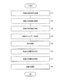
以下に、エネルギー評価装置4の各部の処理について、詳細に説明する。図2は、エネルギー評価装置4の処理フローを示す図である。
<Processing of energy evaluation equipment>
Below, the process of each part of the energy evaluation apparatus 4 is demonstrated in detail. FIG. 2 is a diagram illustrating a processing flow of the energy evaluation device 4.
気温取得部6は、気温測定装置3から気温測定値を取得する(S1)。風量取得部7は、空気調節器2の風量測定部5から風量測定値を取得する(S2)。
The
空気調節器2の暖房風量を少なくすると、気温は低くなり、風量を多くすると、気温は高くなる。ここで、空気調節器2が運転状態にある場合の気温の領域では、通常、風量と気温の関係はリニアの関係にあると想定できる。すなわち、風量の変化に対する気温の変化は、直線的に表すことができると仮定できる。そして、安定状態(定常状態)におけるエネルギー因子と品質管理因子との関係は、事前にエネルギー因子(風量)を様々に変えて、品質管理因子(気温)が安定した時点での品質管理因子の値を記録することにより、取得することができる。安定状態とは、外乱のない、通常想定される使用状態である。このように、エネルギー評価装置4は、あらかじめエネルギー因子の変化と品質管理因子の変化との関係を取得し、エネルギー因子と品質管理因子との関係を例えばテーブルデータとして記憶部11に記憶している。なお、エネルギー因子と品質管理因子との関係を示すデータは、テーブルデータに限らず、関係を表す数式のデータ等であってもよい。また、エネルギー因子と品質管理因子との関係を示すデータは、あらかじめ外部からエネルギー評価装置4に与えられてもよい。
When the air volume of the
風量限界値特定部8は、気温が品質管理基準の限界値(20℃)になるときの風量を推定(特定)する(S3)。ここで、風量の変化と気温の変化とは直線的な関係にあるので、気温および風量の測定値から、気温が品質管理基準の限界値(20℃)になるときの風量(すなわち、消費エネルギーを低減できる風量の限界値)を推定することができる。 The air volume limit value specifying unit 8 estimates (specifies) the air volume when the air temperature reaches the limit value (20 ° C.) of the quality control standard (S3). Here, since the change in the air volume and the change in the air temperature are in a linear relationship, the air volume (that is, the energy consumption) when the temperature becomes the limit value (20 ° C.) of the quality control standard from the measured values of the air temperature and the air volume. Can be estimated.
図3は、風量の変化と気温の変化との関係を示すグラフである。例えば、気温測定装置3および風量測定部5での事前の測定において、点Aの風量xaと気温ya、および点Bの風量xbと気温ybが測定されたとする。なお、点Aおよび点Bの測定は信頼できる測定値である、すなわち、複数回の測定において、点Aと点Bとは統計的に測定点が集中する点である。点Cは、気温取得部6および風量取得部7が取得した現在の気温ycおよび風量xcを示す点である。本実施形態では、風量の変化と気温の変化とは直線的な関係にあると想定できる。点Cは、あらかじめ測定された点Aおよび点Bの測定値と、風量の変化および気温の変化の直線的な関係とから求められる直線の上にほぼ位置する。よって、現在の部屋の気温は安定状態にあると判断できる。それゆえ、部屋の気温が限界値である品質管理基準値の限界値(20℃)になるときの風量xdを、求めた直線に基づいて、特定することができる。気温が品質管理基準値の限界値であるときの気温と風量とを示すのが点Dである。このように、風量限界値特定部8は、あらかじめ風量を変えて複数回測定した気温と風量との関係から、気温が品質管理基準値の限界値であるときの風量xdを特定することができる。求めた風量xdは、品質管理基準を満たしながら下げられる(節約できる)限界の風量に相当する。
FIG. 3 is a graph showing the relationship between the change in air volume and the change in temperature. For example, it is assumed that the air volume xa and the air temperature ya at the point A and the air volume xb and the air temperature yb at the point B are measured in the prior measurement by the
過剰エネルギー特定部9は、現在の風量xcに対応する空気調節器2の消費エネルギーを特定し、気温が品質管理基準値の限界値であるときの風量xdに対応する空気調節器2の消費エネルギーを特定する。現在の風量xcに対応する空気調節器2の消費エネルギーとは、風量がxcである場合の空気調節器2の消費電力である。エネルギー評価装置4は、空気調節器2における風量と消費電力との関係を示すデータを記憶部11にあらかじめ記憶している。風量と消費電力との関係を示すデータは、例えばテーブルデータでもよいし、数式を示すデータであってもよい。過剰エネルギー特定部9は、記憶部11に記憶されている風量と消費電力との関係を示すデータに基づき、風量がxcである場合の空気調節器2の消費電力を特定する。同様にして、過剰エネルギー特定部9は、記憶部11に記憶されている風量と消費電力との関係を示すデータに基づき、風量がxdである場合の空気調節器2の消費電力を特定する。現在の風量の測定値である風量xcが、外乱に備えて余裕分(バッファ)を持ったものになっている場合、風量xcに対応する消費電力も、余裕分のために過剰に大きいものになっている。そのため、風量xcに対応する消費電力と、気温が品質管理基準値の限界値になるときの風量xdに対応する消費電力との差は、バッファのために過剰に消費されているエネルギーということができる。過剰エネルギー特定部9は、風量xcに対応する消費電力と、気温が品質管理基準値の限界値になるときの風量xdに対応する消費電力との差を、過剰エネルギーとして求める(S4)。過剰エネルギーは、品質管理基準を満たすために消費エネルギーに設けられたバッファということができる。
The excess energy specifying unit 9 specifies the energy consumption of the
表示制御部10は、求められた過剰エネルギーを表示装置16に表示(提示)させる制御を行う(S5)。なお、表示制御部10は、現在の消費エネルギーおよび気温が品質管理基準値の限界値になるときの消費エネルギーを、表示装置16に表示させてもよい。利用者は表示装置16に表示された過剰エネルギーを確認することで、消費エネルギーのバッファがどれだけ多いか、どれだけのエネルギーが過剰に消費されているかを認識することができる。
The
ただし、通常は、エネルギーの節約のために過剰エネルギーの全てを削減することはできない。過剰エネルギーの全てを削減すると、安定状態においては気温は品質管理基準を満たす限界値の20℃に維持される。しかしながら、この場合、部屋の扉を開けて外部から部屋に人・物等が入る等の外乱があると、気温は20℃を下回り、品質管理基準を満たさなくなる。生産現場等で常に品質管理基準を満たすことが求められる状況では、品質管理基準の限界値に対してある程度の余裕分(バッファ)を設けることが必要になる。エネルギー評価装置4は、消費エネルギーのバッファのうち、削減可能なエネルギーを特定し、それを削減するよう空気調節器2を制御する。以下にその処理について説明する。
However, it is usually not possible to reduce all of the excess energy to save energy. When all of the excess energy is reduced, the air temperature is maintained at a limit value of 20 ° C. that satisfies the quality control standard in a stable state. However, in this case, if there is a disturbance such as opening a room door and people or objects entering the room from the outside, the temperature falls below 20 ° C. and the quality control standard is not satisfied. In a situation where it is always required to satisfy the quality control standard at a production site or the like, it is necessary to provide a certain margin (buffer) with respect to the limit value of the quality control standard. The energy evaluation device 4 specifies energy that can be reduced from among the buffers of energy consumption, and controls the
削減可能なエネルギーを特定するためには、安定状態における気温をどこまで品質管理基準の限界値に近づけてもよいかを決定する必要がある。外乱等によって気温が下降し始めた場合、気温を品質管理基準の限界値以上に維持するために、空気調節器2の暖房の風量を上げる。しかしながら、安定状態における元々の気温が限界値に近ければ、外乱によって一時的に気温が限界値未満になってしまう。そのため、安定状態においてできる限りエネルギーを節約しながら、十分な余裕を持った温度を、安定状態における気温の目標値にする必要がある。
In order to identify the energy that can be reduced, it is necessary to determine how close the temperature in the stable state may be to the limit value of the quality control standard. When the temperature starts to decrease due to disturbance or the like, the air volume of the
安定状態における気温の目標値は、空気調節器2の即応性と追従性とに基づいて設定できる。空気調節器2は、外乱等による部屋の気温の変動(下降)を検知すると、風量を多くして気温を上昇させようと動作する。即応性は、空気調節器2の出力の変化(上昇)により、品質管理因子である気温(気温測定値)に変化が現れるまでの時間を表す。すなわち、安定状態において空気調節器2の風量が増加してから1秒後に気温の測定値が上昇し始めた場合、即応性は「1秒」ということができる。追従性は、空気調節器2の出力を最大にする場合に、品質管理因子が変動し始めてからの品質管理因子の変化の速さを表す。すなわち、安定状態において空気調節器2が気温を1秒(s)間に0.5℃上昇させることができる場合、追従性は「0.5[℃/s]」ということができる。この場合、即応性を1[s]とすると、空気調節器2によるt秒後(t≧1)の気温上昇量は、0.5[℃/s]×(t[s]−1[s])になる。
The target value of the temperature in the stable state can be set based on the responsiveness and followability of the
また、空気調節器2の出力の変化自体が時間の関数になる場合がある。例えば、空気調節器2の出力を変化させる場合の、出力の変化の度合いが100W/sであり、空気調節器2の1Wの出力で、1秒間当たりに気温を0.005℃上昇させることができる場合、追従性は、以下となる。
In addition, the change in the output of the
(100[W/s])×(0.005[℃/W・s])=0.5[℃/s2]
この場合、即応性を1[s]とすると、空気調節器2は、t秒後(t≧1)には気温を0.5[℃/s2]×(t[s]−1[s])の速度で上昇させることができる。空気調節器2によるt秒後(t≧1)の気温上昇量は、次式で表せる。
(100 [W / s]) × (0.005 [° C./W·s])=0.5 [° C./s 2 ]
In this case, when the responsiveness is 1 [s], the
この例では、追従性は加速度的であり、気温は時間tの2次関数で変化するが、実際の空気調節器2の出力には上限(例えば1000W)がある。そのため、出力の変化自体が時間の関数になる。
In this example, the followability is acceleration and the temperature changes with a quadratic function of time t, but the actual output of the
そして、空気調節器2の出力が一定の時に、外乱等により気温が最大でどの程度変動するかが分かれば、安定状態において維持すべき気温の目標値を決定することができる。例えば、外乱等により、最大で気温が一定の速度2[℃/s]で下降するとする。すなわち、気温が1[s]で2℃下降する。外乱による気温の下降速度2[℃/s]と、空気調節器2の動作による気温の上昇速度0.5[℃/s2]×(t[s]−1[s])とが釣り合うのは、5秒後である。よって、外乱があってから5秒間の間の気温低下量を余裕分(バッファ)とすればよい。部屋の気温が最も低下するのは外乱があってから5秒後である。外乱があってからt秒後(t≧1)の気温低下量は、次式で表すことができる。
Then, when the output of the
よって、5秒後の気温低下量は、−6℃となる。それゆえ、品質管理基準の限界値20℃より6℃高い26℃を、安定状態における気温の目標値として管理すれば、外乱等があった場合でも、気温が常に品質管理基準を満たすように空気調節器2を動作させることができる。よって、安定状態において気温を30℃に維持するよう動作している空気調節器2があれば、気温の目標値を26℃まで低下させて動作させることにより、その差分に対応する風量の消費エネルギーを削減することができる。このようにして求められた気温の目標値は、外乱があった場合にも気温が品質管理基準を満たすという条件において、最も空気調節器2の消費エネルギーを低減することができるものである。
Therefore, the amount of temperature decrease after 5 seconds is −6 ° C. Therefore, if 26 ° C, which is 6 ° C higher than the
性能特定部12は、空気調節器2の即応性および追従性を特定する。具体的には、性能特定部12は、外乱のない安定状態において、空気調節器2の出力を最大に変更させてから品質管理因子(気温)が変化し始めるまでの時間をあらかじめ測定し、即応性として記憶部11に記憶させる。また、性能特定部12は、空気調節器2の出力を最大に変更した場合に、品質管理因子(気温)が変動し始めてからの品質管理因子の時間変化を測定し、追従性として記憶部11に記憶させる。即応性および追従性は、エネルギー因子(風量)の変化に対する品質管理因子(気温)の変化の関係を示す量である。なお、即応性および追従性については、公開されている空気調節器2のスペックに基づいて、利用者が性能特定部12に入力してもよい。また、性能特定部12は、想定される外乱があった場合に、品質管理因子(気温)が最大でどの程度(どれぐらいの速度で)変化するのかをあらかじめ測定し、品質管理因子の最大変化度合いとして記憶部11に記憶させる。なお、即応性、追従性、および品質管理因子の最大変化度合いについては、別に用意した同様の環境であらかじめ測定し、エネルギー評価装置4の記憶部11に記憶させていてもよい。
The
気温目標値特定部13は、安定状態において維持すべき気温の目標値を特定する(S6)。上述したように、安定状態において維持すべき気温の目標値は、外乱がある場合でも品質管理因子である気温が品質管理基準を常に満たすために、品質管理基準の限界値に対してバッファを持った値に設定される。具体的には、気温目標値特定部13は、記憶部11に記憶されている即応性、追従性、および品質管理因子の最大変化度合いに基づいて、気温の目標値を求める。上述の例の場合、気温目標値特定部13は、26℃を気温の目標値として特定する。
The temperature target
風量目標値特定部14は、気温目標値特定部13が特定した気温の目標値に対応する空気調節器2の出力(風量)を特定する(S7)。風量目標値特定部14は、風量限界値特定部8と同様に、あらかじめ測定された風量の変化と気温の変化との関係に基づき、部屋の気温を目標値にする風量を求め、風量の目標値として特定する。
The air volume target value specifying unit 14 specifies the output (air volume) of the
また、過剰エネルギー特定部9は、記憶部11に記憶されている風量と消費電力との関係を示すデータに基づき、風量の目標値に対応する空気調節器2の消費エネルギーを特定する。過剰エネルギー特定部9は、風量の目標値に対応する空気調節器2の消費エネルギーと現在の風量測定値に対応する空気調節器2の消費エネルギーとの差を、削減可能なエネルギーとして特定する。なお、風量と消費エネルギーがリニアな関係にある場合は、過剰エネルギー特定部9は、風量の目標値と、現在の風量測定値との差を求め、この風量の差に相当する消費エネルギーを削減可能なエネルギーとして求めてもよい。
Further, the excess energy specifying unit 9 specifies the energy consumption of the
風量制御部15は、空気調節器2の風量が、風量目標値特定部14が特定した風量の目標値になるよう空気調節器2を制御する(S8)。これにより、部屋の気温を気温の目標値である26℃にし、削減可能なエネルギーを削減することができる。なお、風量制御部15は、空気調節器2の風量を徐々に変化(低下)させ、気温の測定値が気温の目標値になるまで、風量を変化させてもよい。
The air
なお、気温取得部6が気温の急激な変化(気温が目標値より低くなること)を測定した場合、風量制御部15は、空気調節器2の風量を最大にし、外乱等に起因すると考えられる気温の低下を抑制する。これにより、エネルギー評価装置4は、部屋の気温が常に品質管理基準を満たすように空気調節器2を制御し、かつ、外乱に備えた空気調節器2の消費エネルギーのバッファを必要最小限に抑えることができる。
In addition, when the
<その他の変形例>
なお、表示制御部10は、気温目標値特定部13が特定した気温の目標値を表示装置16に表示させてもよい。また、表示制御部10は、風量の目標値を表示装置16に表示させてもよい。品質管理基準を満たしつつ、消費エネルギーを低減することができる気温の目標値または風量の目標値を利用者に提示することで、利用者は空気調節器2を適切な出力で動作するよう設定することができる。また、表示制御部10は、過剰エネルギー特定部9が求めた削減可能なエネルギーを表示装置16に表示させてもよい。削減可能なエネルギーを利用者に提示することで、どの程度のエネルギーが過剰に消費されているのかを利用者が認識することができる。
<Other variations>
Note that the
本実施形態では、エネルギー評価装置4は、エネルギー因子として空気調節器2の風量を取得したが、代わりに空気調節器2の消費電力等を取得してもよい。
In the present embodiment, the energy evaluation device 4 acquires the air volume of the
なお、本実施形態では、品質管理因子として部屋の気温、エネルギー因子として暖房の風量を想定した場合について説明したが、これに限らない。例えば、品質管理因子は、冷却水の水温、生産設備の排熱温度、またはクリーンルームの粒子濃度等、調節可能な物理量であればよい。また、例えば、エネルギー因子は、冷却水の流量、冷却水の水温、生産設備の排気風量、または空気調節器の電力等、品質管理因子の調節およびエネルギーに結びついた物理量であればよい。 In addition, although this embodiment demonstrated the case where the room temperature was assumed as a quality control factor and the air volume of heating was assumed as an energy factor, it is not restricted to this. For example, the quality control factor may be a physical quantity that can be adjusted, such as the temperature of cooling water, the exhaust heat temperature of production equipment, or the concentration of particles in a clean room. Further, for example, the energy factor may be a physical quantity related to the adjustment of the quality control factor and the energy such as the flow rate of the cooling water, the cooling water temperature, the exhaust air volume of the production facility, or the power of the air regulator.
また、部屋に複数の空気調節器が備えられ、エネルギー評価装置が複数の空気調節器の風量を群制御によって制御してもよい。この場合エネルギー評価装置は、各空気調節器について風量の測定値を取得し、各空気調節器の風量を制御する。ここで、空気調節器に限らず一般の装置は、最大出力で動作させた方がエネルギー効率がよいことがある。例えば、部屋に3つの空気調節器が設置されており、気温を目標値に維持するために1つの空気調節器の最大出力の180%に相当する出力が合計で必要な場合、3つの空気調節器を60%ずつで動作させるよりは、100%の出力の空気調節器と、80%の出力の空気調節器と、0%の出力の空気調節器とに分けて動作させた方がエネルギー効率がよいことがある。エネルギー評価装置は、エネルギー評価装置は、複数の空気調節器のうちの1つの空気調節器の風量を様々に変化させたときの、部屋の気温の変化を測定することができる。そのため、エネルギー評価装置の風量目標値特定部は、各空気調節器において出力(風量)レベル毎のエネルギー効率を特定することができる。ここで、エネルギー効率は、風量当たりのまたは消費エネルギー当たりの気温の変化度合いに相当する。よって、エネルギー評価装置の風量制御部は、各空気調節器の出力がエネルギー効率がよい出力レベルに優先的になるよう、各空気調節器の風量を台数制御することができる。 Further, a plurality of air conditioners may be provided in the room, and the energy evaluation device may control the air volumes of the plurality of air conditioners by group control. In this case, the energy evaluation device acquires the measurement value of the air volume for each air regulator and controls the air volume of each air regulator. Here, not only an air conditioner but a general device may be more energy efficient when operated at the maximum output. For example, if three air conditioners are installed in a room and a total output corresponding to 180% of the maximum output of one air conditioner is required to maintain the air temperature at the target value, three air conditioners are required. It is more energy efficient to operate a 100% output air conditioner, an 80% output air conditioner, and a 0% output air conditioner rather than operating at 60% each. May be good. The energy evaluation apparatus can measure a change in room temperature when the air volume of one of the plurality of air conditioners is changed variously. Therefore, the air volume target value specifying unit of the energy evaluation device can specify the energy efficiency for each output (air volume) level in each air regulator. Here, the energy efficiency corresponds to the degree of change in temperature per air volume or per consumed energy. Therefore, the air volume control unit of the energy evaluation device can control the number of air flows of each air conditioner so that the output of each air conditioner has priority over the output level with good energy efficiency.
また、同じ風量、同じ消費エネルギーであっても、空気調節器毎に、気温を調節する能力が異なる場合がある。エネルギー評価装置は、複数の空気調節器のうちの1つの空気調節器の風量を変化させたときの、部屋の気温の変化を測定することができる。そのため、エネルギー評価装置の風量目標値特定部は、いずれの空気調節器を動作させれば、より少ない風量、すなわちより少ないエネルギーで気温を調節することができるかを認識することができる。風量目標値特定部(調節装置特定部)は、よりエネルギー効率のよい空気調節器を特定する、またはよりエネルギー効率のよい空気調節器の出力レベル(例えば、出力レベル80%が最も効率がよい等)を特定することができる。よって、エネルギー評価装置の風量制御部は、よりエネルギー効率のよい空気調節器を優先的に動作させ、全体での消費エネルギーの無駄を削減することができる。 Moreover, even if it is the same air volume and the same energy consumption, the ability to adjust temperature may differ for every air conditioner. The energy evaluation device can measure a change in room temperature when the air volume of one of the plurality of air conditioners is changed. Therefore, the air volume target value specifying unit of the energy evaluation apparatus can recognize which air regulator can be operated to adjust the air temperature with a smaller air volume, that is, with less energy. The air volume target value specifying unit (the adjusting device specifying unit) specifies a more energy efficient air conditioner, or the output level of the more energy efficient air conditioner (for example, an output level of 80% is most efficient, etc.) ) Can be specified. Therefore, the air volume control unit of the energy evaluation apparatus can preferentially operate a more energy efficient air conditioner and reduce waste of energy consumption as a whole.
[実施形態2]
本実施の形態では、複数の溶接装置に冷却水を循環させ、各溶接装置の冷却水の排水時の水温を品質管理因子として管理する場合について説明する。なお、説明の便宜上、実施の形態1にて説明した図面と同じ機能を有する部材・構成については、同じ符号を付記し、その詳細な説明を省略する。以下、本発明の実施形態について、図4〜図5を参照して詳細に説明する。
[Embodiment 2]
In the present embodiment, a case will be described in which cooling water is circulated through a plurality of welding apparatuses and the water temperature at the time of draining the cooling water of each welding apparatus is managed as a quality control factor. For convenience of explanation, members / configurations having the same functions as those in the drawings described in the first embodiment are given the same reference numerals, and detailed descriptions thereof are omitted. Hereinafter, embodiments of the present invention will be described in detail with reference to FIGS.
<溶接装置冷却システムの構成>
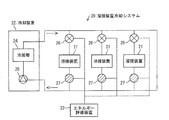
図4は、溶接装置冷却システム20の概略構成を示す図である。溶接装置冷却システム20は、複数(3つ)の溶接装置21と冷却装置(調節装置)22とエネルギー評価装置23とを含む。
<Configuration of welding system cooling system>
FIG. 4 is a diagram showing a schematic configuration of the welding
溶接装置21は、基板等のはんだ付けを行う溶接装置であり、装置の動作時には熱を発生させる。そのため、発生した熱を排熱するために、冷却装置22から各溶接装置21に冷却水の配管が配されている。図4における矢印は、冷却水の流れる方向を示す。各溶接装置21を冷却して温度が高くなって排出された冷却水は、冷却装置22に回収される。
The
冷却装置22は、冷却部24と冷却水圧送ポンプ25とを備える。冷却部24は、電力駆動する冷媒圧縮ポンプを備え、回収されて温まった冷却水を一定の温度に冷却する。冷却水圧送ポンプ25は、冷却水に圧力を加えて流れさせ冷却水を各溶接装置21に供給する。冷却装置22は、冷却部24と冷却水圧送ポンプ25とにおいて、溶接装置21を冷却するためにエネルギー(電力)を消費する。
The cooling device 22 includes a
本実施形態の例では、溶接装置21の内部の温度が高くなりすぎないように、溶接装置21が排出した時点における冷却水の水温が30℃以下になるようにするという品質管理基準が設けられている。
In the example of the present embodiment, a quality control standard is set such that the temperature of the cooling water at the time when the
従来の溶接装置冷却システムでは、一定水温(例えば15℃)の冷却水を一定の流量で各溶接装置に供給していた。しかしながら、溶接装置は動作時により多くの熱を発生させ、その動作状態によっても発生させる熱量は変化する。そのため、溶接装置が動作しているか否かに関わらず一定の水温の冷却水を一定の流量で供給する従来の構成では、冷却水の水温または流量により多くの余裕(バッファ)を見込んでおく必要があった。そのため、冷却装置が消費するエネルギーの無駄があった。 In a conventional welding apparatus cooling system, cooling water having a constant water temperature (for example, 15 ° C.) is supplied to each welding apparatus at a constant flow rate. However, the welding apparatus generates more heat during operation, and the amount of heat generated varies depending on the operation state. Therefore, in the conventional configuration in which the cooling water having a constant water temperature is supplied at a constant flow rate regardless of whether or not the welding apparatus is operating, it is necessary to allow for a large margin (buffer) depending on the cooling water temperature or flow rate. was there. Therefore, there was a waste of energy consumed by the cooling device.
そこで、本実施形態では、エネルギー評価装置23が、各溶接装置21について最適な冷却水の流量を特定し、各溶接装置21に流れる冷却水の流量を調節する。
Therefore, in the present embodiment, the
溶接装置冷却システム20では、溶接装置21毎に、冷却水の配管に流量調節バルブ26と、流量温度センサ27とが設置されている。
In the welding
流量調節バルブ26は、エネルギー評価装置23からの命令によって各溶接装置21に流入する冷却水の流量を調節する。
The flow
流量温度センサ27は、各溶接装置21からの排水の流量と水温とを測定する。流量温度センサ27は、流量と水温の測定値をエネルギー評価装置23に出力する。
The flow
エネルギー評価装置23は、各流量調節バルブ26および各流量温度センサ27に通信可能に接続されている。
The
図5は、エネルギー評価装置23の機能的構成を示すブロック図である。エネルギー評価装置23は、水温取得部(物理量取得部)28、流量取得部(エネルギー因子取得部)29、記憶部11、性能特定部30、水温目標値特定部(物理量目標値特定部)31、流量目標値特定部(エネルギー因子目標値特定部)32、および、流量制御部(エネルギー因子調節部)33を備える。
FIG. 5 is a block diagram showing a functional configuration of the
水温取得部28は、流量温度センサ27から、排水された冷却水の水温を取得する。流量取得部29は、流量温度センサ27から、冷却水の流量を取得する。
The water
記憶部11は、取得された水温測定値、および流量測定値を記憶する。また、記憶部11は、種々のデータを記憶する。
The
性能特定部30は、冷却水による冷却の即応性および追従性を特定する。具体的な処理は後述する。特定した即応性および追従性は、記憶部11に記憶させる。
The
水温目標値特定部31は、各溶接装置21について安定状態において維持すべき水温の目標値を特定し、水温の目標値を流量目標値特定部32に出力する。
The water temperature target
流量目標値特定部32は、各溶接装置21の水温の目標値に対応する冷却水の流量を特定し、各溶接装置21の冷却水の流量の目標値として流量制御部33に出力する。
The flow rate target
流量制御部33は、流量調節バルブ26を調節し、各溶接装置21の冷却水の流量を制御する。
The flow
<エネルギー評価装置の処理>
以下に、エネルギー評価装置23の各部の処理について、詳細に説明する。
<Processing of energy evaluation equipment>
Below, the process of each part of the
水温取得部28は、流量温度センサ27から、排水された冷却水の水温を取得する。流量取得部29は、流量温度センサ27から、冷却水の流量を取得する。
The water
各溶接装置21に流入する冷却水の流量を少なくすると、排水時の冷却水の温度は高くなり、冷却水の流量を多くすると、排水時の冷却水の温度は低くなる。本実施形態では、各溶接装置21について、排水時の冷却水の水温が品質管理因子であり、各溶接装置21に流入する冷却水の流量がエネルギー因子である。そして、溶接装置21が高レベルで動作している状態(より多くの熱を発生させている状態)が外乱のある状態に対応する。エネルギー評価装置23は、実施形態1と同様に、溶接装置21が待機状態(または低レベルで動作している状態)のときに、事前にエネルギー因子(流量)を様々に変えて、品質管理因子(水温)の値を記録することにより、安定状態におけるエネルギー因子と品質管理因子との関係を取得することができる。エネルギー評価装置23は、あらかじめエネルギー因子の変化と品質管理因子の変化との関係を取得し、エネルギー因子と品質管理因子との関係を例えばテーブルデータとして記憶部11に記憶している。
When the flow rate of the cooling water flowing into each
性能特定部30は、冷却水の流量の変化による即応性および追従性を特定する。具体的には、性能特定部30は、安定状態(各溶接装置21が待機状態または低レベルで動作している状態)において、ある溶接装置21の冷却水の流量を最大に変更させてから品質管理因子(排水水温)が変化し始めるまでの時間をあらかじめ測定し、即応性として記憶部11に記憶させる。また、性能特定部30は、当該溶接装置21の冷却水の流量を最大に変更した場合に、品質管理因子(排水水温)が変動し始めてからの品質管理因子の時間変化を測定し、追従性として記憶部11に記憶させる。また、性能特定部30は、溶接装置21が高レベルで動作した場合に、品質管理因子(排水水温)が最大でどの程度(どれぐらいの速度で)変化するのかをあらかじめ測定し、品質管理因子の最大変化度合いとして記憶部11に記憶させる。なお、複数の溶接装置21の性能が互いに異なる場合、動作時の最大の発熱量等も異なる。そのため、性能特定部30は、複数の溶接装置21毎に、即応性、追従性、および品質管理因子の最大変化度合いを求めて、それらを記憶部11に記憶させる。なお、即応性、追従性、および品質管理因子の最大変化度合いについては、別に用意した同様の環境であらかじめ測定し、エネルギー評価装置23の記憶部11に記憶させていてもよい。
The
水温目標値特定部31は、安定状態において維持すべき排水水温の目標値を特定する。実施形態1と同様にして、水温目標値特定部31は、記憶部11に記憶されている即応性、追従性、および品質管理因子の最大変化度合いに基づいて、各溶接装置21の排水水温の目標値を求める。複数の溶接装置21毎に、即応性、追従性、および品質管理因子の最大変化度合いが異なる場合、溶接装置21毎に排水水温の目標値を求める。
The water temperature target
流量目標値特定部32は、水温目標値特定部31が特定した排水水温の目標値に対応する冷却水の流量を特定する。流量目標値特定部32は、あらかじめ測定された冷却水の流量の変化と排水水温の変化との関係に基づき、各溶接装置21について、排水水温を目標値にする冷却水の流量を求め、冷却水の流量の目標値として特定する。冷却水の流量の目標値も、溶接装置21毎に異なりうる。
The flow rate target
流量制御部33は、各溶接装置21に流入する冷却水の流量が、各溶接装置21についての冷却水の流量の目標値になるよう、流量調節バルブ26を制御し、冷却水の流量を調節する。これにより、エネルギー評価装置23は、各溶接装置21に供給する冷却水の流量を最適に制御することができる。全体の冷却水の流量が少なくなれば、冷却装置22の冷却部24が循環する冷却水の冷却を行うために消費するエネルギーも小さくなる。そのため、エネルギー評価装置23は、品質管理基準を常に満たせる状態で、冷却装置22の消費エネルギーを最適化することができる、すなわち、消費エネルギーにおける余裕分(バッファ)を必要最小限に抑えることができる。
The flow
なお、水温取得部28がいずれかの溶接装置21の排水水温の急激な変化(排水水温が目標値より高くなること)を測定した場合、流量制御部33は、当該溶接装置21の冷却水の流量を最大にし、溶接装置21の動作に起因する排水水温の上昇を抑制する。
In addition, when the water
[実施形態3]
本実施の形態では、1つの品質管理因子に対してエネルギー因子が2つある場合について説明する。なお、説明の便宜上、実施の形態2にて説明した図面と同じ機能を有する部材・構成については、同じ符号を付記し、その詳細な説明を省略する。以下、本発明の実施形態について、図6〜図7を参照して詳細に説明する。
[Embodiment 3]
In the present embodiment, a case where there are two energy factors for one quality control factor will be described. For convenience of explanation, members / configurations having the same functions as those in the drawings described in the second embodiment are given the same reference numerals, and detailed descriptions thereof are omitted. Hereinafter, embodiments of the present invention will be described in detail with reference to FIGS.
<溶接装置冷却システムの構成>
図6は、溶接装置冷却システム40の概略構成を示す図である。溶接装置冷却システム40は、1つの溶接装置21と冷却装置22とエネルギー評価装置42とを含む。
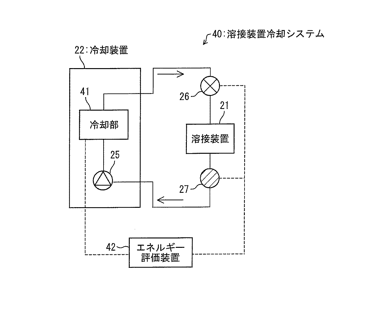
<Configuration of welding system cooling system>
FIG. 6 is a diagram showing a schematic configuration of the welding
溶接装置21の構成は、実施形態2と同様である。
The configuration of the
冷却装置22は、冷却部41と冷却水圧送ポンプ25とを備える。冷却部41は、回収されて温まった冷却水を、エネルギー評価装置42によって指定された所定の温度に冷却する。実施形態2とは異なり、冷却部41は、エネルギー評価装置42からの命令に従って冷却水の水温を調節する。また、冷却部41は、冷却して供給する冷却水の水温をエネルギー評価装置42に出力する。冷却水圧送ポンプ25は、冷却水に圧力を加えて流れさせ冷却水を溶接装置21に供給する。冷却装置22は、冷却部41と冷却水圧送ポンプ25とにおいて、溶接装置21を冷却するためにエネルギーを消費する。
The cooling device 22 includes a
本実施形態の例では、溶接装置21の内部の温度が高くなりすぎないように、溶接装置21が排出した時点における冷却水の水温が30℃以下になるようにするという品質管理基準が設けられている。
In the example of the present embodiment, a quality control standard is set such that the temperature of the cooling water at the time when the
本実施形態では、エネルギー評価装置42が、溶接装置21について最適な冷却水の供給時の水温と流量とを特定し、溶接装置21に流れる冷却水の水温および流量を調節する。
In the present embodiment, the
溶接装置冷却システム40では、溶接装置21毎に、冷却水の配管に流量調節バルブ26と、流量温度センサ27とが設置されている。
In the welding
流量調節バルブ26は、エネルギー評価装置42からの命令によって溶接装置21に流入する冷却水の流量を調節する。
The flow
流量温度センサ27は、溶接装置21からの排水の流量と水温とを測定する。流量温度センサ27は、流量と水温の測定値をエネルギー評価装置42に出力する。
The flow
エネルギー評価装置23は、冷却装置22、流量調節バルブ26および流量温度センサ27に通信可能に接続されている。
The
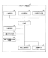
図7は、エネルギー評価装置42の機能的構成を示すブロック図である。エネルギー評価装置42は、水温取得部28、流量取得部29、記憶部11、冷却温度取得部(エネルギー因子取得部)43、性能特定部44、水温目標値特定部45、流量冷却温度目標値特定部(エネルギー因子目標値特定部)46、流量制御部47、および、冷却温度制御部(エネルギー因子調節部)48を備える。
FIG. 7 is a block diagram showing a functional configuration of the
水温取得部28は、流量温度センサ27から、排水された冷却水の水温を取得する。流量取得部29は、流量温度センサ27から、冷却水の流量を取得する。冷却温度取得部43は、冷却装置22の冷却部41から冷却した冷却水の温度(冷却温度)を取得する。なお、冷却温度取得部43は、温度の実測値ではなく、冷却部41の冷却温度の設定値を取得してもよいし、冷却温度制御部48等から冷却部41に指示する冷却温度の設定値を取得してもよい。
The water
記憶部11は、取得された水温測定値、流量測定値、冷却温度を記憶する。また、記憶部11は、種々のデータを記憶する。
The memory |
性能特定部44は、冷却水による冷却の即応性および追従性を特定する。具体的な処理は後述する。特定した即応性および追従性は、記憶部11に記憶させる。
The performance specifying unit 44 specifies the responsiveness and followability of cooling with cooling water. Specific processing will be described later. The specified responsiveness and followability are stored in the
水温目標値特定部45は、溶接装置21について安定状態において維持すべき水温の目標値を特定し、水温の目標値を流量冷却温度目標値特定部46に出力する。
The water temperature target
流量冷却温度目標値特定部46は、溶接装置21の水温の目標値に対応する冷却水の流量および冷却温度を特定し、溶接装置21の冷却水の流量の目標値および冷却温度の目標値として、それぞれ流量制御部47および冷却温度制御部48に出力する。
The flow rate cooling temperature target
流量制御部47は、流量調節バルブ26を調節し、溶接装置21の冷却水の流量を制御する。
The flow
冷却温度制御部48は、冷却装置22の冷却部41に冷却温度の設定値を出力し、冷却部41の冷却温度を制御する。
The cooling
<エネルギー評価装置の処理>
以下に、エネルギー評価装置42の各部の処理について、詳細に説明する。
<Processing of energy evaluation equipment>
Below, the process of each part of the
水温取得部28は、流量温度センサ27から、排水された冷却水の水温を取得する。流量取得部29は、流量温度センサ27から、冷却水の流量を取得する。冷却温度取得部43は、冷却装置22の冷却部41から冷却した冷却水の温度(冷却温度)を取得する。
The water
溶接装置21に流入する冷却水の流量を少なくすると、排水時の冷却水の温度は高くなり、冷却水の流量を多くすると、排水時の冷却水の温度は低くなる。また、冷却部41の冷却温度を低くすると、排水時の冷却水の温度は低くなり、冷却部41の冷却温度を高くすると、排水時の冷却水の温度は高くなる。本実施形態では、溶接装置21の排水時の冷却水の水温が品質管理因子であり、溶接装置21に流入する冷却水の流量および冷却部41の冷却温度がエネルギー因子である。エネルギー評価装置40は、実施形態2と同様に、溶接装置21が待機状態(または低レベルで動作している状態)のときに、事前に2つのエネルギー因子(流量および冷却温度)をそれぞれ独立に変化させ、品質管理因子(排水水温)の値を記録することにより、安定状態における2つのエネルギー因子と品質管理因子との関係を取得することができる。エネルギー評価装置40は、あらかじめ各エネルギー因子の変化と品質管理因子の変化との関係を取得し、各エネルギー因子と品質管理因子との関係を例えばテーブルデータとして記憶部11に記憶している。
If the flow rate of the cooling water flowing into the
性能特定部44は、冷却水の流量の変化による即応性および追従性と、冷却部41の冷却温度の変化による即応性および追従性とを特定する。具体的には、実施形態2と同様に、性能特定部44は、安定状態(溶接装置21が待機状態または低レベルで動作している状態)において、溶接装置21の冷却水の流量を最大かつ冷却部41の出力を最大(冷却温度を最低)に変更させてから品質管理因子(排水水温)が変化し始めるまでの時間をあらかじめ測定し、即応性として記憶部11に記憶させる。また、性能特定部44は、溶接装置21の冷却水の流量を最大かつ冷却部41の出力を最大に変更した場合に、品質管理因子(排水水温)が変動し始めてからの品質管理因子の時間変化を測定し、追従性として記憶部11に記憶させる。また、性能特定部44は、溶接装置21が高レベルで動作した場合に、品質管理因子(排水水温)が最大でどの程度(どれぐらいの速度で)変化するのかをあらかじめ測定し、品質管理因子の最大変化度合いとして記憶部11に記憶させる。
The performance specifying unit 44 specifies the responsiveness and followability due to the change in the flow rate of the cooling water, and the responsiveness and followability due to the change in the cooling temperature of the cooling
水温目標値特定部45は、安定状態において維持すべき排水水温の目標値を特定する。実施形態2と同様にして、水温目標値特定部45は、記憶部11に記憶されている即応性、追従性、および品質管理因子の最大変化度合いに基づいて、排水水温の目標値を求める。
The water temperature target
流量冷却温度目標値特定部46は、水温目標値特定部45が特定した排水水温の目標値に対応する冷却水の流量および冷却部41の冷却温度を特定する。流量冷却温度目標値特定部46は、あらかじめ測定された冷却水の流量の変化と排水水温の変化との関係および冷却温度の変化と排水水温の変化との関係に基づき、溶接装置21について、排水水温を目標値にする冷却水の流量と冷却温度の組み合わせを求める。ここで、独立に調節可能なエネルギー因子が2つ(流量および冷却温度)あるので、排水水温を目標値にするような冷却水の流量と冷却温度の組み合わせは、1つだけではなく、複数あることが考えられる。そこで、流量冷却温度目標値特定部46は、排水水温を目標値にするような冷却水の流量と冷却温度の複数の組み合わせの中から、対応する消費エネルギー(冷却装置22の消費エネルギー)がより低くなる(最も低くなる)組み合わせを特定する。そして、流量冷却温度目標値特定部46は、特定した組み合わせの冷却水の流量を、冷却水の流量の目標値として特定し、特定した組み合わせの冷却温度を、冷却温度の目標値として特定する。
The flow rate cooling temperature target
なお、実施形態1と同様に、エネルギー評価装置42は、冷却装置22における流量および冷却温度と、消費電力との関係を示すデータを記憶部11にあらかじめ記憶している。流量および冷却温度と消費電力との関係を示すデータは、例えばテーブルデータでもよいし、数式を示すデータであってもよい。流量冷却温度目標値特定部46は、記憶部11に記憶されている流量および冷却温度と消費電力との関係を示すデータに基づき、排水水温を目標値にするような冷却水の流量と冷却温度の複数の組み合わせの中から、対応する消費エネルギーがより低くなる組み合わせを特定する。
As in the first embodiment, the
流量制御部47は、溶接装置21に流入する冷却水の流量が、冷却水の流量の目標値になるよう、流量調節バルブ26を制御し、冷却水の流量を調節する。
The flow
冷却温度制御部48は、冷却装置22の冷却部41に冷却温度の設定値を出力し、冷却部41の冷却温度が、冷却温度の目標値になるよう制御する。
The cooling
これにより、エネルギー評価装置42は、供給する冷却水の流量および冷却温度を最適に制御することができる。エネルギー評価装置42は、安定状態において冷却水の流量を絞ることと冷却温度を上げることとのバランスを考慮して、最もエネルギー効率がよい(余裕分(バッファ)のために消費するエネルギーが最も小さい)冷却水の流量と冷却温度の組み合わせを特定する。そのため、エネルギー評価装置42は、品質管理基準を常に満たせる状態で、冷却装置22の消費エネルギーを最適化することができる、すなわち、消費エネルギーにおける余裕分(バッファ)を必要最小限に抑えることができる。
Thereby, the
最後に、エネルギー評価装置4、23、42の各ブロック、特に気温取得部6、風量取得部7、風量限界値特定部8、過剰エネルギー特定部9、表示制御部10、記憶部11、性能特定部12、30、44、気温目標値特定部13、風量目標値特定部14、風量制御部15、水温取得部28、流量取得部29、性能特定部30、水温目標値特定部31、45、流量目標値特定部32、流量制御部33、47、冷却温度取得部43、流量冷却温度目標値特定部46、および、冷却温度制御部48は、ハードウェアロジックによって構成してもよいし、次のようにCPU(central processing unit)を用いてソフトウェアによって実現してもよい。
Finally, each block of the
すなわち、エネルギー評価装置4、23、42は、各機能を実現する制御プログラムの命令を実行するCPU、上記プログラムを格納したROM(read only memory)、上記プログラムを展開するRAM(random access memory)、上記プログラムおよび各種データを格納するメモリ等の記憶装置(記録媒体)などを備えている。そして、本発明の目的は、上述した機能を実現するソフトウェアであるエネルギー評価装置4、23、42の制御プログラムのプログラムコード(実行形式プログラム、中間コードプログラム、ソースプログラム)をコンピュータで読み取り可能に記録した記録媒体を、上記エネルギー評価装置4、23、42に供給し、そのコンピュータ(またはCPUやMPU(microprocessor unit))が記録媒体に記録されているプログラムコードを読み出し実行することによっても、達成可能である。
That is, the
上記記録媒体としては、例えば、磁気テープやカセットテープ等のテープ系、フロッピー(登録商標)ディスク/ハードディスク等の磁気ディスクやCD−ROM(compact disc read-only memory)/MO(magneto-optical)/MD(Mini Disc)/DVD(digital versatile disk)/CD−R(CD Recordable)等の光ディスクを含むディスク系、ICカード(メモリカードを含む)/光カード等のカード系、あるいはマスクROM/EPROM(erasable programmable read-only memory)/EEPROM(electrically erasable and programmable read-only memory)/フラッシュROM等の半導体メモリ系などを用いることができる。 Examples of the recording medium include a tape system such as a magnetic tape and a cassette tape, a magnetic disk such as a floppy (registered trademark) disk / hard disk, a CD-ROM (compact disc read-only memory) / MO (magneto-optical) / Disk systems including optical disks such as MD (Mini Disc) / DVD (digital versatile disk) / CD-R (CD Recordable), card systems such as IC cards (including memory cards) / optical cards, or mask ROM / EPROM ( An erasable programmable read-only memory) / EEPROM (electrically erasable and programmable read-only memory) / semiconductor memory system such as a flash ROM can be used.
また、エネルギー評価装置4、23、42を通信ネットワークと接続可能に構成し、上記プログラムコードを通信ネットワークを介して供給してもよい。この通信ネットワークとしては、特に限定されず、例えば、インターネット、イントラネット、エキストラネット、LAN(local area network)、ISDN(integrated services digital network)、VAN(value-added network)、CATV(community antenna television)通信網、仮想専用網(virtual private network)、電話回線網、移動体通信網、衛星通信網等が利用可能である。また、通信ネットワークを構成する伝送媒体としては、特に限定されず、例えば、IEEE(institute of electrical and electronic engineers)1394、USB、電力線搬送、ケーブルTV回線、電話線、ADSL(asynchronous digital subscriber loop)回線等の有線でも、IrDA(infrared data association)やリモコンのような赤外線、Bluetooth(登録商標)、802.11無線、HDR(high data rate)、携帯電話網、衛星回線、地上波デジタル網等の無線でも利用可能である。
Further, the
本発明は上述した各実施形態に限定されるものではなく、請求項に示した範囲で種々の変更が可能であり、異なる実施形態にそれぞれ開示された技術的手段を適宜組み合わせて得られる実施形態についても本発明の技術的範囲に含まれる。 The present invention is not limited to the above-described embodiments, and various modifications are possible within the scope shown in the claims, and embodiments obtained by appropriately combining technical means disclosed in different embodiments. Is also included in the technical scope of the present invention.
本発明は、消費エネルギーを評価するまたは最適化するエネルギー評価装置に利用することができる。 The present invention can be used in an energy evaluation apparatus that evaluates or optimizes energy consumption.
1 気温調節システム
2 空気調節器(調節装置)
3 気温測定装置
4、23、42 エネルギー評価装置
5 風量測定部
6 気温取得部(物理量取得部)
7 風量取得部(エネルギー因子取得部)
8 風量限界値特定部(限界値特定部)
9 過剰エネルギー特定部(削減可能エネルギー特定部)
10 表示制御部(提示部)
11 記憶部
12、30、44 性能特定部(関係特定部)
13 気温目標値特定部(物理量目標値特定部)
14 風量目標値特定部(エネルギー因子目標値特定部、調節装置特定部)
15 風量制御部(エネルギー因子調節部)
16 表示装置
20、40 溶接装置冷却システム
21 溶接装置
22 冷却装置(調節装置)
24、41 冷却部
25 冷却水圧送ポンプ
26 流量調節バルブ
27 流量温度センサ
28 水温取得部(物理量取得部)
29 流量取得部(エネルギー因子取得部)
31、45 水温目標値特定部(物理量目標値特定部)
32 流量目標値特定部(エネルギー因子目標値特定部)
33、47 流量制御部(エネルギー因子調節部)
43 冷却温度取得部(エネルギー因子取得部)
46 流量冷却温度目標値特定部(エネルギー因子目標値特定部)
48 冷却温度制御部(エネルギー因子調節部)
1
3 Air
7 Air volume acquisition unit (energy factor acquisition unit)
8 Airflow limit value specifying part (limit value specifying part)
9 Excess energy specific part (Reducible energy specific part)
10 Display control unit (presentation unit)
11
13 Temperature target value specifying part (physical quantity target value specifying part)
14 Airflow target value specifying unit (energy factor target value specifying unit, regulator specifying unit)
15 Air volume control unit (energy factor adjustment unit)
16
24, 41
29 Flow rate acquisition unit (energy factor acquisition unit)
31, 45 Water temperature target value specifying part (physical quantity target value specifying part)
32 Flow rate target value specifying part (energy factor target value specifying part)
33, 47 Flow control unit (energy factor adjustment unit)
43 Cooling temperature acquisition unit (energy factor acquisition unit)
46 Flow rate cooling temperature target value specifying part (energy factor target value specifying part)
48 Cooling temperature controller (energy factor controller)
Claims (9)
上記調節装置の出力を変更させてから上記物理量が変化し始めるまでの時間と、上記調節装置の出力を変更させた場合における上記物理量が変化し始めてからの上記物理量の変化の速さとを記憶する記憶部と、
上記物理量の測定値を取得する物理量取得部と、
上記調節装置の消費エネルギーの因子となるエネルギー因子の値を取得するエネルギー因子取得部と、
外乱がないときの上記物理量の目標値を特定する物理量目標値特定部とを備え、
上記物理量目標値特定部は、あらかじめ取得した上記エネルギー因子の変化に対する上記物理量の変化の関係と、外乱に起因する想定される上記物理量の変化とに基づき、外乱があった場合にも上記物理量が上記管理基準を外れることがないようにするための余裕分を持った上記物理量の値を、上記物理量の目標値として特定し、
上記物理量目標値特定部は、上記記憶部に記憶された上記時間と上記速さとに基づいて算出した、上記調節装置の出力を変更させてからの上記物理量の変化の速さと、外乱に起因する想定される上記物理量の変化の速さとが釣り合うまでの時間における上記物理量の変化量を上記余裕分として算出することを特徴とするエネルギー評価装置。 An energy evaluation device for evaluating energy consumption for an adjustment device that adjusts the physical quantity by consuming energy so that the physical quantity to be managed satisfies a predetermined management standard,
The time until the physical quantity starts changing after the output of the adjusting device is changed and the speed of change of the physical quantity after the physical quantity starts changing when the output of the adjusting device is changed are stored. A storage unit;
A physical quantity acquisition unit for acquiring a measured value of the physical quantity;
An energy factor acquisition unit that acquires a value of an energy factor that is a factor of energy consumption of the adjusting device;
A physical quantity target value specifying unit for specifying the target value of the physical quantity when there is no disturbance,
The physical quantity target value specifying unit, based on the relationship between the physical quantity change obtained in advance with respect to the change in the energy factor and the assumed change in the physical quantity caused by the disturbance, The physical quantity value having a margin to prevent the management standard from being deviated is specified as the target value of the physical quantity,
The physical quantity target value specifying unit is calculated based on the time and the speed stored in the storage unit, resulting from a change in the physical quantity after changing the output of the adjusting device and a disturbance. An energy evaluation apparatus characterized in that a change amount of the physical quantity in a time until a speed of change of the assumed physical quantity is balanced is calculated as the margin.
上記物理量目標値特定部は、あらかじめ取得した上記エネルギー因子の変化に対する上記物理量の変化の関係と、外乱に起因する想定される上記物理量の変化とに基づき、想定される最大の外乱があった場合に上記物理量が上記管理基準を満たすための最小限の余裕分を持った上記物理量の値を、上記物理量の目標値として特定することを特徴とする請求項3に記載のエネルギー評価装置。 The energy factor adjustment unit adjusts the energy factor so as to suppress the variation of the physical quantity when the measured value of the physical quantity varies from the target value of the physical quantity,
The physical quantity target value specifying unit is based on the assumed relationship between the change in the physical quantity with respect to the change in the energy factor acquired in advance and the assumed change in the physical quantity caused by the disturbance. The energy evaluation apparatus according to claim 3 , wherein the physical quantity value having a minimum margin for satisfying the management standard is specified as a target value of the physical quantity.
外乱がない状態において、上記エネルギー因子を変化させて上記物理量の測定値の変化を取得し、上記複数の調節装置のうち、上記物理量をより少ない消費エネルギーで調節する上記調節装置を特定する調節装置特定部を備え、
上記エネルギー因子調節部は、上記調節装置特定部が特定した上記調節装置のエネルギー因子を、優先的に調節することを特徴とする請求項3に記載のエネルギー評価装置。 For one physical quantity, there are a plurality of adjusting devices for adjusting the physical quantity,
In a state where there is no disturbance, the energy factor is changed to obtain a change in the measured value of the physical quantity, and the adjusting device that specifies the adjusting device that adjusts the physical quantity with less energy consumption among the plurality of adjusting devices. With a specific part,
The energy evaluation device according to claim 3 , wherein the energy factor adjustment unit preferentially adjusts the energy factor of the adjustment device specified by the adjustment device specifying unit.
上記調節装置の出力を変更させてから上記物理量が変化し始めるまでの時間と、上記調節装置の出力を変更させた場合における上記物理量が変化し始めてからの上記物理量の変化の速さとを保持しておき、
上記物理量の測定値を取得する物理量取得ステップと、
上記調節装置の消費エネルギーの因子となるエネルギー因子の値を取得するエネルギー因子取得ステップと、
外乱がないときの上記物理量の目標値を特定する物理量目標値特定ステップとを含み、
上記物理量目標値特定ステップでは、あらかじめ取得した上記エネルギー因子の変化に対する上記物理量の変化の関係と、外乱に起因する想定される上記物理量の変化とに基づき、外乱があった場合にも上記物理量が上記管理基準を外れることがないようにするための余裕分を持った上記物理量の値を、上記物理量の目標値として特定し、
上記物理量目標値特定ステップでは、保持されている上記時間と上記速さとに基づいて算出した、上記調節装置の出力を変更させてからの上記物理量の変化の速さと、外乱に起因する想定される上記物理量の変化の速さとが釣り合うまでの時間における上記物理量の変化量を上記余裕分として算出することを特徴とするエネルギー評価方法。 An energy evaluation method for evaluating energy consumption for an adjustment device that adjusts the physical quantity by consuming energy so that the physical quantity to be managed satisfies a predetermined management standard,
The time until the physical quantity starts to change after changing the output of the adjusting device, and the speed of change of the physical quantity after the physical quantity starts changing when the output of the adjusting device is changed are held. Leave
A physical quantity acquisition step of acquiring a measured value of the physical quantity;
An energy factor acquisition step of acquiring a value of an energy factor that is a factor of energy consumption of the regulator;
A physical quantity target value specifying step for specifying a target value of the physical quantity when there is no disturbance,
In the physical quantity target value specifying step, the physical quantity is determined even when there is a disturbance based on the relationship between the change in the physical quantity with respect to the change in the energy factor acquired in advance and the assumed change in the physical quantity caused by the disturbance. The physical quantity value having a margin to prevent the management standard from being deviated is specified as the target value of the physical quantity,
In the physical quantity target value specifying step, the speed of change of the physical quantity after changing the output of the adjusting device, which is calculated based on the held time and speed, is assumed due to disturbance. An energy evaluation method, wherein the amount of change of the physical quantity in a time until the speed of change of the physical quantity is balanced is calculated as the margin.
上記調節装置の出力を変更させてから上記物理量が変化し始めるまでの時間と、上記調節装置の出力を変更させた場合における上記物理量が変化し始めてからの上記物理量の変化の速さとを保持しておき、
上記物理量の測定値を取得する物理量取得ステップと、
上記調節装置の消費エネルギーの因子となるエネルギー因子の値を取得するエネルギー因子取得ステップと、
あらかじめ取得した上記エネルギー因子の変化に対する上記物理量の変化の関係と、外乱に起因する想定される上記物理量の変化とに基づき、外乱があった場合にも上記物理量が上記管理基準を外れることがないようにするための余裕分を持った上記物理量の値を、外乱がないときの上記物理量の目標値として特定する物理量目標値特定ステップとをコンピュータに実行させ、
上記物理量目標値特定ステップでは、保持されている上記時間と上記速さとに基づいて算出した、上記調節装置の出力を変更させてからの上記物理量の変化の速さと、外乱に起因する想定される上記物理量の変化の速さとが釣り合うまでの時間における上記物理量の変化量を上記余裕分として算出することを特徴とする制御プログラム。 About the adjusting device that adjusts the physical quantity by consuming energy so that the physical quantity to be managed satisfies the predetermined management standard,
The time until the physical quantity starts to change after changing the output of the adjusting device, and the speed of change of the physical quantity after the physical quantity starts changing when the output of the adjusting device is changed are held. Leave
A physical quantity acquisition step of acquiring a measured value of the physical quantity;
An energy factor acquisition step of acquiring a value of an energy factor that is a factor of energy consumption of the regulator;
Based on the relationship between the change in the physical quantity to the change in the energy factor acquired in advance and the assumed change in the physical quantity due to the disturbance, the physical quantity does not deviate from the management standard even when there is a disturbance. Causing the computer to execute a physical quantity target value specifying step for specifying the physical quantity value having a margin for making the physical quantity target value when there is no disturbance,
In the physical quantity target value specifying step, the speed of change of the physical quantity after changing the output of the adjusting device, which is calculated based on the held time and speed, is assumed due to disturbance. A control program for calculating, as the margin, a change amount of the physical quantity in a time until the speed of change of the physical quantity is balanced.
Priority Applications (3)
| Application Number | Priority Date | Filing Date | Title |
|---|---|---|---|
| JP2010198215A JP5287811B2 (en) | 2010-09-03 | 2010-09-03 | Energy evaluation apparatus, energy evaluation method, and control program |
| PCT/JP2011/056275 WO2012029343A1 (en) | 2010-09-03 | 2011-03-16 | Energy evaluation device, energy evaluation method, and control program |
| CN201180034804.8A CN103003835B (en) | 2010-09-03 | 2011-03-16 | Heat-supplied device, energy evaluation method and control program |
Applications Claiming Priority (1)
| Application Number | Priority Date | Filing Date | Title |
|---|---|---|---|
| JP2010198215A JP5287811B2 (en) | 2010-09-03 | 2010-09-03 | Energy evaluation apparatus, energy evaluation method, and control program |
Publications (2)
| Publication Number | Publication Date |
|---|---|
| JP2012058781A JP2012058781A (en) | 2012-03-22 |
| JP5287811B2 true JP5287811B2 (en) | 2013-09-11 |
Family
ID=45772459
Family Applications (1)
| Application Number | Title | Priority Date | Filing Date |
|---|---|---|---|
| JP2010198215A Active JP5287811B2 (en) | 2010-09-03 | 2010-09-03 | Energy evaluation apparatus, energy evaluation method, and control program |
Country Status (3)
| Country | Link |
|---|---|
| JP (1) | JP5287811B2 (en) |
| CN (1) | CN103003835B (en) |
| WO (1) | WO2012029343A1 (en) |
Families Citing this family (2)
| Publication number | Priority date | Publication date | Assignee | Title |
|---|---|---|---|---|
| JP6305677B2 (en) * | 2012-10-10 | 2018-04-04 | 横河電機株式会社 | Energy-saving operation evaluation system |
| CN107798472B (en) * | 2017-10-20 | 2021-11-30 | 重庆长安汽车股份有限公司 | Analysis method for whole vehicle energy flow distribution and fuel consumption influence factor evaluation |
Family Cites Families (7)
| Publication number | Priority date | Publication date | Assignee | Title |
|---|---|---|---|---|
| JPH0593539A (en) * | 1991-10-01 | 1993-04-16 | Matsushita Electric Ind Co Ltd | Controller for air conditioning system |
| JPH07332740A (en) * | 1994-06-03 | 1995-12-22 | Toshiba Corp | Operation control method of air conditioner |
| CN1200463A (en) * | 1997-05-23 | 1998-12-02 | 台湾得意温控科技股份有限公司 | Temp. control method for central air conditioner system by intermittent wind blowing control |
| JP4294021B2 (en) * | 2005-12-22 | 2009-07-08 | イーキュービック株式会社 | Energy consumption consumption calculation system and method |
| CN100480593C (en) * | 2006-12-31 | 2009-04-22 | 广州金关节能科技发展有限公司 | Air-conditioning energy-saving monitoring system of base station |
| JP5113631B2 (en) * | 2007-07-24 | 2013-01-09 | パナソニック株式会社 | Electricity usage notification system |
| JP4920027B2 (en) * | 2008-12-04 | 2012-04-18 | 株式会社Nttファシリティーズ | Linkage control method for air conditioning equipment and ICT equipment |
-
2010
- 2010-09-03 JP JP2010198215A patent/JP5287811B2/en active Active
-
2011
- 2011-03-16 WO PCT/JP2011/056275 patent/WO2012029343A1/en active Application Filing
- 2011-03-16 CN CN201180034804.8A patent/CN103003835B/en active Active
Also Published As
| Publication number | Publication date |
|---|---|
| CN103003835A (en) | 2013-03-27 |
| JP2012058781A (en) | 2012-03-22 |
| CN103003835B (en) | 2016-09-21 |
| WO2012029343A1 (en) | 2012-03-08 |
Similar Documents
| Publication | Publication Date | Title |
|---|---|---|
| US20130268126A1 (en) | Air conditioning information estimation device, control method of air conditioning information estimation device, and control program | |
| US10169833B2 (en) | Using customer premises to provide ancillary services for a power grid | |
| US11060745B1 (en) | Energy reduction | |
| WO2015075794A1 (en) | Power demand prediction system, power demand prediction method, customer profiling system, and customer profiling method | |
| CN108917117B (en) | Air conditioner and control method and device thereof | |
| CN110223005B (en) | Air conditioner load power supply reliability assessment method and assessment device | |
| US20150362206A1 (en) | System and method to manage energy consumption in an hvac system | |
| US10620244B2 (en) | Remote leak and failure detection of electrical water heaters through temperature and power monitoring | |
| US10655874B1 (en) | Enthalpy measurement and system control | |
| US10760814B2 (en) | Variable-capacity compressor controller with two-wire configuration | |
| CN113294885B (en) | Air conditioner control method and device, air conditioner and computer readable storage medium | |
| US11353232B2 (en) | Control method, control apparatus, and non-transitory computer-readable storage medium for storing program | |
| CN110375422B (en) | Control method and system of air conditioner and air conditioning equipment | |
| US10830474B2 (en) | Systems and methods of predicting energy usage | |
| JP5287811B2 (en) | Energy evaluation apparatus, energy evaluation method, and control program | |
| JP2015183935A (en) | Facility control device, facility management method and program | |
| CN111023523A (en) | Air conditioner control method and device, air conditioner and storage medium | |
| CN115017006A (en) | Auxiliary energy-saving control method and system for data center | |
| JP6258487B2 (en) | Energy network heat demand adjustment apparatus and energy network heat demand adjustment method | |
| JP2013040705A (en) | Controller, control method, control program and recording medium | |
| CN107894076B (en) | Multi-split air conditioning system, energy-saving control method and device thereof and storage medium | |
| US11543163B2 (en) | Method and system for charge determination | |
| WO2014010186A1 (en) | Air conditioning control device, air conditioning control system, air conditioning system and program | |
| JP7332865B2 (en) | Information processing method, information processing device, and program | |
| CN112364999A (en) | Training method and device for water chiller adjustment model and electronic equipment |
Legal Events
| Date | Code | Title | Description |
|---|---|---|---|
| A131 | Notification of reasons for refusal |
Free format text: JAPANESE INTERMEDIATE CODE: A131 Effective date: 20121113 |
|
| A521 | Request for written amendment filed |
Free format text: JAPANESE INTERMEDIATE CODE: A523 Effective date: 20130109 |
|
| A131 | Notification of reasons for refusal |
Free format text: JAPANESE INTERMEDIATE CODE: A131 Effective date: 20130205 |
|
| A521 | Request for written amendment filed |
Free format text: JAPANESE INTERMEDIATE CODE: A523 Effective date: 20130327 |
|
| TRDD | Decision of grant or rejection written | ||
| A01 | Written decision to grant a patent or to grant a registration (utility model) |
Free format text: JAPANESE INTERMEDIATE CODE: A01 Effective date: 20130507 |
|
| A61 | First payment of annual fees (during grant procedure) |
Free format text: JAPANESE INTERMEDIATE CODE: A61 Effective date: 20130520 |
|
| R150 | Certificate of patent or registration of utility model |
Ref document number: 5287811 Country of ref document: JP Free format text: JAPANESE INTERMEDIATE CODE: R150 |
|
| RD02 | Notification of acceptance of power of attorney |
Free format text: JAPANESE INTERMEDIATE CODE: R3D02 |
|
| RD04 | Notification of resignation of power of attorney |
Free format text: JAPANESE INTERMEDIATE CODE: R3D04 |
|
| R250 | Receipt of annual fees |
Free format text: JAPANESE INTERMEDIATE CODE: R250 |
|
| R250 | Receipt of annual fees |
Free format text: JAPANESE INTERMEDIATE CODE: R250 |
|
| R250 | Receipt of annual fees |
Free format text: JAPANESE INTERMEDIATE CODE: R250 |