JP5287623B2 - Virtual server management system, image processing system, virtual server management apparatus, and control program - Google Patents
Virtual server management system, image processing system, virtual server management apparatus, and control program Download PDFInfo
- Publication number
- JP5287623B2 JP5287623B2 JP2009210613A JP2009210613A JP5287623B2 JP 5287623 B2 JP5287623 B2 JP 5287623B2 JP 2009210613 A JP2009210613 A JP 2009210613A JP 2009210613 A JP2009210613 A JP 2009210613A JP 5287623 B2 JP5287623 B2 JP 5287623B2
- Authority
- JP
- Japan
- Prior art keywords
- virtual server
- server
- information
- function
- unit
- Prior art date
- Legal status (The legal status is an assumption and is not a legal conclusion. Google has not performed a legal analysis and makes no representation as to the accuracy of the status listed.)
- Expired - Fee Related
Links
Images


Landscapes
- Data Exchanges In Wide-Area Networks (AREA)
Description
本発明は、仮想サーバ管理システム、画像処理システム、仮想サーバ管理装置及び制御プログラムに関し、特に、仮想サーバの起動及び終了の自動化に関する。 The present invention relates to a virtual server management system, an image processing system, a virtual server management apparatus, and a control program, and more particularly to automation of activation and termination of a virtual server.
複数のコンピュータ間のTCP/IPネットワーク環境における通信は、IPアドレスによって各コンピュータが識別され、通信が行われる。このIPアドレスは静的に割り当てられる場合や、DHCP(Dynamic Host Configuration Protocol)のように動的に割り当てられる場合がある。このIPアドレスは、数字の羅列によって示される情報であるところ、ユーザによる識別性やプログラムによる処理の利便性を向上するため、ホスト名によって置き換えられて用いられることが行われている。 In communication in a TCP / IP network environment between a plurality of computers, each computer is identified by an IP address, and communication is performed. This IP address may be statically assigned or may be dynamically assigned such as DHCP (Dynamic Host Configuration Protocol). This IP address is information indicated by an enumeration of numbers, and is used by being replaced by a host name in order to improve identification by a user and convenience of processing by a program.
ホスト名とはIPアドレスとの対応付けがなされた情報であり、ホスト名によって通信先が指定された場合、通信端末であるコンピュータは、内部に保有するホスト名のリストや、DNS(Domain Name System)サービスによって、ホスト名からIPアドレスを取得する。このようにホスト名を用いることにより、通信端末の識別を人間にとって容易にすると同時に、コンピュータの変更によりIPアドレスが変更された場合に、多数のコンピュータで指定先を変更することなく、DNSサービスだけを変更することで対応することができる。 A host name is information associated with an IP address. When a communication destination is specified by a host name, a computer as a communication terminal can store a list of host names held inside, a DNS (Domain Name System), or the like. ) Obtain the IP address from the host name by the service. By using the host name in this way, it is easy for humans to identify the communication terminal, and at the same time, when the IP address is changed due to a change in the computer, only the DNS service is used without changing the designation destination in many computers. You can respond by changing
また、上記DNSサービスにおいて、ホスト名とIPアドレスとの対応関係を動的に更新するDDNS(Dynamic DNS)環境においては、1つのホスト名に複数のIPアドレスを割り当てることで、通信のたびに通信先のコンピュータを変更するが可能である。この技術によって、一台のコンピュータとの通信が途絶えても他のコンピュータとの通信が可能になり、耐故障性が高まるなどの利点がある。 In the DNS service, in a DNS (Dynamic DNS) environment in which the correspondence between the host name and the IP address is dynamically updated, a plurality of IP addresses are assigned to one host name, so that communication is performed every time communication is performed. It is possible to change the destination computer. With this technology, even if communication with one computer is interrupted, it is possible to communicate with other computers, and there is an advantage that fault tolerance is improved.
このようなDDNS環境において、ホスト名が変更された場合や、他の機器と重複した場合であっても、適切な名前解決をDNSサーバに実行させることができる方法が提案されている(例えば、特許文献1参照)。特許文献1に開示された技術においては、変更によって付与されたホスト名とは異なる別名であって、機器毎に一意に定まるエイリアス名をDNSサーバに登録することにより、DDNS環境におけるホスト名の課題を解決している。
In such a DDNS environment, even when the host name is changed or when the host name is duplicated with another device, a method capable of causing the DNS server to perform appropriate name resolution has been proposed (for example, Patent Document 1). In the technique disclosed in
また、近年、複数のサーバ等の情報処理装置が互いに情報をやり取りしながら連動して処理を実行することが可能な情報処理環境において、上述したIPアドレスやホスト名が個別に設定された仮想的なサーバを構築する技術が知られている。このような仮想化技術においては、新規にIPアドレス及びホスト名を設定するだけで、物理的なサーバと同様に振る舞う仮想サーバをネットワーク上に構築することが可能である。 In recent years, in an information processing environment in which information processing apparatuses such as a plurality of servers exchange information with each other and execute processing in conjunction with each other, the above-described virtual IP addresses and host names are individually set. A technique for constructing a secure server is known. In such a virtualization technology, it is possible to construct a virtual server on the network that behaves like a physical server by simply setting a new IP address and host name.
このような仮想化技術を用いてネットワークを介したサービスを提供する場合、システムの負荷状況に応じて起動させる仮想サーバの数を増減させることが行われる。従って、仮想サーバが互いに通信する場合、通信相手のホスト名が頻繁に変わるため、ホスト名解決のための仕組みが重要になる。上述したような仮想化環境を独自に開発してサービスを提供する場合、ホスト名を付与するルールをも独自に構築することができるため、ホスト名の管理も容易である。 When a service is provided via a network using such a virtualization technology, the number of virtual servers to be activated is increased or decreased according to the system load status. Therefore, when the virtual servers communicate with each other, the host name of the communication partner changes frequently, so a mechanism for host name resolution becomes important. When a virtual environment such as that described above is developed and a service is provided, a rule for assigning a host name can also be independently constructed, so that host names can be easily managed.
他方、他社によって提供されている仮想化環境のサービス(以降、仮想環境サービスとする)を利用して、自社のサービスを提供する場合、ホスト名の付与は、提供される仮想環境サービスのルールに則るため、そのルールに則ってホスト名解決の仕組みを構築する必要がある。ここで、他社による仮想環境サービスを利用する場合、新たに起動した仮想サーバが、既に起動している仮想サーバと同一のサブネット内に配置されるとは限らないため、ホスト名を確認するためにブロードキャストを行うことができない。 On the other hand, when providing a company's service using a virtual environment service provided by another company (hereinafter referred to as a virtual environment service), the host name is assigned according to the rules of the provided virtual environment service. Therefore, it is necessary to construct a host name resolution mechanism according to the rules. Here, when using a virtual environment service provided by another company, the newly started virtual server is not necessarily placed in the same subnet as the already started virtual server. Cannot broadcast.
更に、他社による仮想環境サービスを利用する場合、同様に仮想環境サービスを利用している他人若しくは他社の仮想サーバが同一のサブネット内に配置されている可能性もあり、この点からもブロードキャストを行うことは好ましくない。このような課題は、予めホスト名のリストを設けておき、そのリストに従って処理が行われるような場合に特に問題となる。 Furthermore, when using a virtual environment service by another company, there is a possibility that another person who uses the virtual environment service or a virtual server of another company is also located in the same subnet. That is not preferable. Such a problem is particularly problematic when a list of host names is provided in advance and processing is performed according to the list.
更に、ネットワークを介したサービスにおいては、様々な機能を有する複数のサーバが互いに連動して動作するため、仮想サーバの増減においては、新たに起動したサーバや、終了したサーバが、どの機能を担っていたのかを把握する必要がある。しかしながら、特許文献1等の従来技術においては、そこまでの仕組みは考慮されていない。
Furthermore, in a service via a network, a plurality of servers having various functions operate in conjunction with each other. Therefore, in the increase / decrease of the virtual server, which function the newly activated server or the terminated server plays. It is necessary to know what was happening. However, the prior art such as
本発明は、このような課題を解決するためになされたものであり、仮想サーバ環境において、仮想サーバが増減された場合に増減された仮想サーバの機能を把握し、予め定められたホスト名のリストに従ってホスト名を付与して通信を行うことを目的とする。 The present invention has been made to solve such a problem, and in a virtual server environment, when the number of virtual servers is increased or decreased, the functions of the increased or decreased virtual servers are grasped, and a predetermined host name is determined. The purpose is to perform communication by assigning a host name according to the list.
上記課題を解決するために、本発明の一態様は、ネットワーク上に接続された情報処理装置によって構成される仮想サーバを、前記仮想サーバを識別する識別情報と前記仮想サーバのネットワークアドレスを関連付けて記憶することにより管理する仮想サーバ管理部と、前記仮想サーバ管理部に対して前記ネットワーク上において起動している仮想サーバの負荷状態に応じて仮想サーバの起動を要求する仮想サーバ起動要求部と、前記仮想サーバの機能の情報を、前記識別情報と関連付けて記憶している仮想サーバ機能管理部と、前記仮想サーバの機能別に予め定められたホスト名のリストに従って前記仮想サーバのネットワークアドレスと前記ホスト名との対応関係を管理する通信制御部とを含む仮想サーバ管理システムであって、前記仮想サーバ管理部が、前記仮想サーバ起動要求部からの要求に応じて前記識別情報及び前記仮想サーバのネットワークアドレスを新たに設定して仮想サーバを新たに起動し且つ前記設定した識別情報及び前記ネットワークアドレスを前記仮想サーバ起動要求部に送信すると共に、前記通信制御部からの要求に応じて記憶している識別情報及びネットワークアドレスを送信し、前記仮想サーバ起動要求部が、前記仮想サーバの起動によって受信した前記識別情報及び前記仮想サーバに担わせる機能の情報を前記仮想サーバ機能管理部に記憶させ、前記仮想サーバ機能管理部が、前記通信制御部からの要求に応じて、起動されている前記仮想サーバの機能の情報を前記通信制御部に送信し、前記通信制御部が、前記仮想サーバ管理部から前記記憶されている識別情報及びネットワークアドレスを取得し、前記仮想サーバ機能管理部から前記仮想サーバの機能の情報を取得し、前記取得したネットワークアドレスを前記取得した仮想サーバの機能の情報に従って前記仮想サーバの機能別に予め定められたホスト名に関連付けて記憶することを特徴とする。 In order to solve the above problem, one aspect of the present invention, a virtual server configured by an information processing apparatus connected to the network, associating the network address of the virtual server identification information for identifying the virtual server A virtual server management unit that manages the virtual server, and a virtual server activation request unit that requests the virtual server management unit to activate a virtual server according to a load state of the virtual server activated on the network. , A virtual server function management unit that stores information on the function of the virtual server in association with the identification information, a network address of the virtual server according to a list of host names predetermined for each function of the virtual server, and the A virtual server management system including a communication control unit that manages a correspondence relationship with a host name. A server management unit newly sets the identification information and the network address of the virtual server in response to a request from the virtual server activation request unit, newly starts a virtual server, and sets the identification information and the network address. Is transmitted to the virtual server activation request unit, and the stored identification information and network address are transmitted in response to a request from the communication control unit, and the virtual server activation request unit is received by activation of the virtual server. The virtual server function management unit stores the identification information and the function information to be assigned to the virtual server, and the virtual server function management unit is activated in response to a request from the communication control unit. Server function information is transmitted to the communication control unit, and the communication control unit stores the stored information from the virtual server management unit. The virtual server function is acquired according to the virtual server function information obtained from the virtual server function management unit, the virtual server function information is acquired from the virtual server function management unit, and the virtual server function information is acquired from the virtual server function management unit. Another feature is that the information is stored in association with a predetermined host name.
ここで、前記仮想サーバ起動要求部が、前記仮想サーバの起動によって受信した前記識別情報及び前記機能の情報を前記仮想サーバ機能管理部に記憶させると共に、前記通信制御部に前記仮想サーバのネットワークアドレスとホスト名との対応関係の更新要求を送信し、前記通信制御部が、前記更新要求に応じて、前記仮想サーバ管理部から前記記憶されている識別情報及びネットワークアドレスを取得し、前記仮想サーバ機能管理部から前記仮想サーバの機能の情報を取得することが好ましい。 Here, the virtual server activation request unit stores the identification information and the function information received by the activation of the virtual server in the virtual server function management unit, and causes the communication control unit to store the network address of the virtual server. And the communication control unit acquires the stored identification information and network address from the virtual server management unit in response to the update request, and the virtual server It is preferable to acquire the function information of the virtual server from the function management unit.
また、前記通信制御部は、定期的に前記仮想サーバ管理部から前記記憶されている識別情報及びネットワークアドレスを取得し、前記仮想サーバ機能管理部から前記仮想サーバの機能の情報を取得することもできる。 Further, the communication control unit periodically acquires the stored identification information and network address from the virtual server management unit, and acquires information on the function of the virtual server from the virtual server function management unit. it can.
また、前記通信制御部は、前記仮想サーバにおいて前記ネットワーク上における通信を制御していることが好ましい。 The communication control unit preferably controls communication on the network in the virtual server.
また、前記通信制御部は、少なくとも1つの前記仮想サーバにおいて構成され、他の仮想サーバは、前記通信制御部を含む仮想サーバにアクセスすることによって前記ホスト名に基づいて前記ネットワークアドレスを取得することもできる。 The communication control unit is configured in at least one of the virtual servers, and the other virtual server acquires the network address based on the host name by accessing a virtual server including the communication control unit. You can also.
また、前記通信制御部は、前記ホスト名のリストに含まれる全てのホスト名に対して前記ネットワーク上において起動している仮想サーバのネットワークアドレスのいずれかを関連付けて管理することが好ましい。 In addition, it is preferable that the communication control unit manages all the host names included in the host name list in association with any of the network addresses of virtual servers running on the network.
また、前記仮想サーバによって実現される機能によって処理可能な情報処理の実行命令を取得し、取得した実行命令を複数の仮想サーバのいずれかに割り振る実行命令割り振り部を更に含み、前記実行命令割り振り部は、前記予め定められたホスト名に従って前記実行命令を割り振ることが好ましい。 The execution instruction allocating unit further includes an execution instruction allocating unit that acquires an execution instruction of information processing that can be processed by the function realized by the virtual server, and allocates the acquired execution instruction to any of a plurality of virtual servers. Preferably assigns the execution instruction according to the predetermined host name.
また、前記予め定められたホスト名のリストは、前記仮想サーバの機能を示す情報と連続する数値とからなる文字列のリストであることが好ましい。 The predetermined list of host names is preferably a list of character strings composed of information indicating the function of the virtual server and a continuous numerical value.
また、前記通信制御部は、前記ネットワーク上において起動している仮想サーバのネットワークアドレスを、前記ホスト名に対して前記連続する数値の順に関連付けることにより前記ホスト名と前記ネットワークアドレスとを関連付けて管理することが好ましい。 In addition, the communication control unit associates and manages the host name and the network address by associating the network address of the virtual server running on the network with the host name in the order of the consecutive numerical values. It is preferable to do.
また、本発明の他の態様は、上述したいずれかの仮想サーバ管理システムによって構成される画像処理システムであって、前記実行命令割り振り部によって割り振られた前記実行命令の情報を記憶する実行命令記憶部と、前記記憶された実行命令の情報を取得して前記実行命令に係る情報処理としての画像処理を実行する画像処理部とを含むことを特徴とする。 According to another aspect of the present invention, there is provided an image processing system configured by any one of the virtual server management systems described above, wherein the execution instruction storage stores information on the execution instruction allocated by the execution instruction allocation unit. And an image processing unit that acquires information of the stored execution instruction and executes image processing as information processing related to the execution instruction.
また、前記仮想サーバ起動要求部は、前記実行命令記憶部に記憶された前記実行命令の蓄積状態に応じて前記仮想サーバの起動を要求することが好ましい。 Further, it is preferable that the virtual server activation request unit requests activation of the virtual server according to an accumulation state of the execution instructions stored in the execution instruction storage unit.
また、前記仮想サーバ起動要求部は、前記画像処理システムを構成している前記仮想サーバを制御する演算装置の負荷状態に応じて前記仮想サーバの起動を要求することが好ましい。 In addition, it is preferable that the virtual server activation request unit requests activation of the virtual server according to a load state of an arithmetic device that controls the virtual server configuring the image processing system.
また、本発明の更に他の態様は、ネットワーク上に接続された情報処理装置によって構成される仮想サーバを制御する仮想サーバ制御装置であって、前記仮想サーバの機能別に予め定められたホスト名のリストに従って前記仮想サーバのネットワークアドレスと前記ホスト名との対応関係を管理し、前記ネットワーク上の通信を制御する通信制御部と、前記仮想サーバを識別する識別情報と前記仮想サーバのネットワークアドレスを関連付けて記憶している仮想サーバ管理部から前記記憶されている識別情報及びネットワークアドレスを取得すると共に、前記仮想サーバの機能の情報を前記識別情報と関連付けて記憶している仮想サーバ機能管理部から前記仮想サーバの機能の情報を取得する情報取得部と、前記取得したネットワークアドレスを前記取得した仮想サーバの機能の情報に従って前記仮想サーバの機能別に予め定められたホスト名に関連付けて記憶することにより前記仮想サーバのネットワークアドレスと前記ホスト名との対応関係を更新する情報更新部とを含むことが好ましい。 According to still another aspect of the present invention, there is provided a virtual server control device that controls a virtual server configured by an information processing device connected to a network, the host name being predetermined for each function of the virtual server. The correspondence between the network address of the virtual server and the host name is managed according to the list, the communication control unit for controlling communication on the network, the identification information for identifying the virtual server, and the network address of the virtual server are associated The stored identification information and network address are acquired from the stored virtual server management unit, and the function information of the virtual server is stored in association with the identification information from the virtual server function management unit. An information acquisition unit that acquires information on the function of the virtual server, and the acquired network address. An information update unit that updates a correspondence relationship between the network address of the virtual server and the host name by storing in association with a host name predetermined for each function of the virtual server according to the acquired function information of the virtual server Are preferably included.
また、前記情報取得部は、前記ネットワーク上において起動している仮想サーバの負荷状態に応じて前記仮想サーバの追加起動を要求する仮想サーバ起動要求部からの通知に応じて、前記記憶されている識別情報及びネットワークアドレス並びに前記仮想サーバの機能の情報を取得することが好ましい。 Further, the information acquisition unit is stored in response to a notification from a virtual server activation request unit that requests additional activation of the virtual server according to a load state of a virtual server activated on the network. It is preferable to acquire identification information, a network address, and function information of the virtual server.
また、本発明の更に他の態様は、情報処理装置を、ネットワーク上に接続された情報処理装置によって構成される仮想サーバを制御する仮想サーバ制御装置として機能させる制御プログラムであって、前記仮想サーバの機能別に予め定められたホスト名のリストに従って前記仮想サーバのネットワークアドレスと前記ホスト名との対応関係を管理し、前記ネットワーク上の通信を制御するステップと、前記仮想サーバを識別する識別情報と前記仮想サーバのネットワークアドレスを関連付けて記憶している仮想サーバ管理部から前記記憶されている識別情報及びネットワークアドレスを取得すると共に、前記仮想サーバの機能の情報を前記識別情報と関連付けて記憶している仮想サーバ機能管理部から前記仮想サーバの機能の情報を取得するステップと、前記取得したネットワークアドレスを前記取得した仮想サーバの機能の情報に従って前記仮想サーバの機能別に予め定められたホスト名に関連付けて記憶することにより、前記仮想サーバのネットワークアドレスと前記ホスト名との対応関係を更新するステップとを前記情報処理装置に実行させることを特徴とする。 According to still another aspect of the present invention, there is provided a control program that causes an information processing apparatus to function as a virtual server control apparatus that controls a virtual server configured by an information processing apparatus connected on a network, the virtual server Managing the correspondence between the network address of the virtual server and the host name in accordance with a list of host names predetermined for each function, controlling communication on the network, and identification information for identifying the virtual server; Obtaining the stored identification information and network address from the virtual server management unit storing the network address of the virtual server in association with each other, and storing the function information of the virtual server in association with the identification information; The function information of the virtual server from the existing virtual server function management unit And storing the acquired network address in association with a host name predetermined for each function of the virtual server according to the acquired function information of the virtual server, and storing the network address of the virtual server and the host name The information processing apparatus is caused to execute the step of updating the correspondence relationship.
本発明によれば、仮想サーバ環境において、仮想サーバが増減された場合に増減された仮想サーバの機能を把握し、予め定められたホスト名のリストに従ってホスト名を付与して通信を行うことができる。 According to the present invention, in a virtual server environment, when a virtual server is increased or decreased, the function of the increased or decreased virtual server is grasped, and communication is performed by assigning a host name according to a predetermined list of host names. it can.
以下、図面を参照して、本発明の実施形態を詳細に説明する。本実施形態においては、仮想サーバ環境を利用して画像処理のネットワークサービスを提供する場合を例として説明する。 Hereinafter, embodiments of the present invention will be described in detail with reference to the drawings. In this embodiment, a case where a network service for image processing is provided using a virtual server environment will be described as an example.
図1は、本実施の形態に係る仮想サーバ管理システムを利用した画像処理システムの運用形態を示す図である。図1に示すように、本実施形態に係る画像処理システムにおいては、仮想サーバ環境を提供する提供者(以降、仮想環境提供者とする)のネットワークAと、画像処理のネットワークサービス(以降、画像処理サービスとする)を提供するサービス提供者(以降、画像処理サービス提供者)のネットワークBと、画像処理サービスを利用するサービス利用者のネットワークCとが、インターネットや電話回線等の公衆回線Dを介して接続されている。 FIG. 1 is a diagram showing an operation mode of an image processing system using a virtual server management system according to the present embodiment. As shown in FIG. 1, in the image processing system according to the present embodiment, a network A of a provider that provides a virtual server environment (hereinafter referred to as a virtual environment provider) and a network service of image processing (hereinafter referred to as an image). A network B of a service provider (hereinafter referred to as an image processing service provider) that provides a processing service) and a network C of a service user that uses the image processing service use a public line D such as the Internet or a telephone line. Connected through.
ネットワークAには、連動して動作する複数の物理サーバ1が接続されており、この物理サーバ1において動作しているアプリケーションの機能によって、仮想サーバ環境が提供される。ネットワークBには、画像処理サービス提供者のオペレータが操作する端末であるクライアント端末2が接続されている。ネットワークCには、画像処理システムを利用するユーザが操作する画像処理装置3が接続されている。
A plurality of
クライアント端末2は、一般的な情報処理端末であり、PC(Personal Computer)等の情報処理装置によって実現される。画像処理装置3は、撮像機能、画像形成機能及び通信機能等を備えることにより、プリンタ、ファクシミリ、スキャナ、複写機として利用可能な複合機である。また、画像処理装置3は、本実施形態に係る画像処理システムにおける画像処理の実行を命令するためのユーザインタフェースとしても機能する。
The client terminal 2 is a general information processing terminal, and is realized by an information processing apparatus such as a PC (Personal Computer). The
次に、本実施形態に係る物理サーバ1、クライアント端末2及び画像処理装置3のハードウェア構成について説明する。図2は、本実施形態に係るクライアント端末2のハードウェア構成を示すブロック図である。尚、画像処理装置3は、図2に示すハードウェア構成に加えて、スキャナ、プリンタ等を実現するためのエンジンを備える。以下の説明においては、クライアント端末2のハードウェア構成を例として説明するが、物理サーバ1及び画像処理装置3についても同様である。
Next, the hardware configuration of the
図2に示すように、本実施形態に係るクライアント端末2は、一般的なサーバやPC等と同様の構成を含む。即ち、本実施形態に係るクライアント端末2は、CPU(Central Processing Unit)10、RAM(Random Access Memory)20、ROM(Read Only Memory)30、HDD(Hard Disk Drive)40及びI/F50がバス80を介して接続されている。また、I/F50にはLCD(Liquid Crystal Display)60及び操作部70が接続されている。
As shown in FIG. 2, the client terminal 2 according to the present embodiment includes the same configuration as that of a general server or PC. That is, the client terminal 2 according to the present embodiment includes a CPU (Central Processing Unit) 10, a RAM (Random Access Memory) 20, a ROM (Read Only Memory) 30, an HDD (Hard Disk Drive) 40, and an I /
CPU10は演算手段であり、クライアント端末2全体の動作を制御する。RAM20は、情報の高速な読み書きが可能な揮発性の記憶媒体であり、CPU10が情報を処理する際の作業領域として用いられる。ROM30は、読み出し専用の不揮発性記憶媒体であり、ファームウェア等のプログラムが格納されている。HDD40は、情報の読み書きが可能な不揮発性の記憶媒体であり、OS(Operating System)や各種の制御プログラム、アプリケーション・プログラム等が格納される。
The CPU 10 is a calculation means and controls the operation of the entire client terminal 2. The
I/F50は、バス80と各種のハードウェアやネットワーク等を接続し制御する。LCD60は、操作者がクライアント端末2の状態を確認するための視覚的ユーザインタフェースである。操作部70は、キーボードやマウス等、操作者がクライアント端末2に情報を入力するためのユーザインタフェースである。尚、図1において説明したように、本実施形態に係る物理サーバ1は、サーバとして運用される。従って、LCD60及び操作部70等のユーザインタフェースは省略可能である。
The I /
このようなハードウェア構成において、ROM30やHDD40若しくは図示しない光学ディスク等の記憶媒体に格納されたプログラムがRAM20に読み出され、CPU10の制御に従って動作することにより、ソフトウェア制御部が構成される。このようにして構成されたソフトウェア制御部と、ハードウェアとの組み合わせによって、本実施形態に係る仮想サーバ環境や、情報処理システムの機能が実現される。
In such a hardware configuration, a program stored in a storage medium such as the
次に、ネットワークAの物理サーバ1において実現される仮想的な環境について、図3を参照して説明する。図3に示すように、本実施形態に係る仮想環境においては、ネットワーク上に仮想管理サーバ4、データベースサーバ5及び複数の仮想サーバ6が接続されたように振る舞う仮想環境が構築される。仮想管理サーバ4は、仮想サーバ6の起動及び終了を管理する管理サーバであり、本実施形態においては、仮想環境を利用する利用者(本実施形態においては、仮想環境を利用して画像処理サービスを提供するサービス提供者)の指示に応じて、仮想サーバ6の起動若しくは終了を管理する。
Next, a virtual environment realized in the
データベースサーバ5は、仮想環境における仮想サーバ6の情報を記憶しているデータベースである。本実施形態に係るデータベースサーバ5は、起動している仮想サーバ6の機能の情報を記憶している。尚、仮想管理サーバ4及びデータベースサーバ5は、仮想環境を提供する提供者によって提供されるサーバであり、仮想サーバとしてではなく、物理サーバとして実現しても良い。
The
複数の仮想サーバ6は、上述したように、物理サーバ1において動作するアプリケーションにより、ネットワーク上において実際の物理サーバと同様に振る舞う仮想的な情報処理装置であり、サーバとしての識別子、ネットワーク上のアドレスであるIPアドレス及びホスト名が設定される。本実施形態に係る仮想サーバ6は、画像処理サービスのシステム負荷に応じて数が増減される。
As described above, the plurality of virtual servers 6 are virtual information processing apparatuses that behave in the same manner as an actual physical server on the network by an application that operates on the
次に、本実施形態において、画像処理サービス提供者によって仮想サーバ6によって構築される画像処理システムについて、図4を参照して説明する。図4に示すように、本実施形態に係る画像処理システムにおいては、ネットワーク上にロードバランササーバ100、モニターサーバ200、タスク管理サーバ300、ワーカーサーバ400及びタスク記憶サーバ500が接続されたように振る舞う画像処理システムが仮想的に実現される。尚、タスク管理サーバ300、ワーカーサーバ400及びタスク記憶サーバ500は、システムの負荷状態に応じて複数構成される。
Next, an image processing system constructed by the virtual server 6 by the image processing service provider in the present embodiment will be described with reference to FIG. As shown in FIG. 4, the image processing system according to the present embodiment behaves as if the
ロードバランササーバ100は、本実施形態に係る画像処理システムにおいて、画像処理サービスを利用するサービス利用者(以降、ユーザとする)に対して窓口となる構成であり、ユーザが画像処理装置3を操作して入力したジョブを取得し、複数のタスク管理サーバ300に順番に割り振る。これにより、処理が分散され、システムの安定稼働が実現される。モニターサーバ200は、タスク管理サーバ300、ワーカーサーバ400及びタスク記憶サーバ500の負荷状況を監視しており、夫々の負荷状況に応じて、夫々のサーバの起動若しくは終了を仮想管理サーバ4に要求する。これにより、システム負荷が高い場合は、処理がより分散されるようにサーバ数が増え、システム負荷が低い場合は、効率的な動作のためにサーバ数が減ることとなる。
The
タスク管理サーバ300は、ロードバランササーバ100によって割り振られたタスクを管理するサーバである。また、タスク管理サーバ300は、ワーカーサーバ400に実行させるまでもない画像処理を実行する機能も含む。ワーカーサーバ400は、画像処理システムにおいて実際の画像処理を実行するサーバである。タスク記憶サーバ500は、タスク管理サーバ300がロードバランササーバ100によって割り振られたタスクを記憶するサーバである。
The
次に、本実施形態に係る仮想管理サーバ4の機能構成について、図5を参照して説明する。図5に示すように、本実施形態に係る仮想管理サーバ4は、仮想サーバ起動管理部4a、仮想サーバ情報記憶部4b及び通信制御部4cを含む。上述したように、仮想サーバ起動管理部4a及び通信制御部4cは、図2に示すHDD40等の記憶媒体に記憶されている制御プログラムが、RAM20にロードされ、CPU10の制御に従って動作することにより構成される。また、仮想サーバ情報記憶部4bは、図2に示すHDD40等の記憶媒体によって構成される。
Next, the functional configuration of the virtual management server 4 according to the present embodiment will be described with reference to FIG. As shown in FIG. 5, the virtual management server 4 according to the present embodiment includes a virtual server activation management unit 4a, a virtual server
仮想サーバ起動管理部4aは、上述したモニターサーバ200の要求に基づき、仮想サーバ6の起動及び終了を管理する。仮想サーバ起動管理部4aは、仮想サーバ6を起動する場合、図2において説明したHDD40等の記憶媒体に記憶されているプログラムであって、サーバを実現するためのプログラムをコピーしてRAM20にロードし、CPU10に制御させることによって仮想サーバ6を起動する。また、仮想サーバ起動管理部4aは、起動した仮想サーバ6に対して、識別子及びネットワーク上のアドレスであるIPアドレスを設定し、仮想サーバ情報記憶部4bに記憶させる。
The virtual server activation management unit 4a manages activation and termination of the virtual server 6 based on the request from the
仮想サーバ情報記憶部4bは、上述したように、起動している仮想サーバ6の識別子及びIPアドレスを関連付けて記憶している記憶媒体である。図6に、仮想サーバ情報記憶部4bが記憶している情報の例を示す。通信制御部4cは、仮想サーバ起動管理部4aが仮想的なネットワークを介してデータベースサーバ5や仮想サーバ6と情報をやり取りするためのネットワークインタフェースである。
As described above, the virtual server
尚、本実施形態において、仮想サーバ起動管理部4aは、新たに仮想サーバ6を起動すると、上述した識別子及びIPアドレスに加えてホスト名も設定する。このホスト名は、例えばMACアドレス等、一意に決定される情報が用いられる。従って、仮想管理サーバ4に含まれる通信制御部4cは、上記仮想サーバ起動管理部4aによって設定されたホスト名の解決に対応したDNS(Domain Name System)環境(以降、第1のDNS環境とする)により情報通信を行う。 In the present embodiment, when the virtual server activation management unit 4a newly activates the virtual server 6, it sets a host name in addition to the identifier and IP address described above. For this host name, for example, uniquely determined information such as a MAC address is used. Accordingly, the communication control unit 4c included in the virtual management server 4 has a DNS (Domain Name System) environment (hereinafter referred to as a first DNS environment) corresponding to the resolution of the host name set by the virtual server activation management unit 4a. ) To communicate information.
次に、データベースサーバ5の機能構成について、図7を参照して説明する。図7に示すように、本実施形態に係るデータベースサーバ5は、通信制御部5a及びサーバ機能情報記憶部5bを含む。通信制御部5aは、仮想管理サーバ4に含まれる通信制御部4cと同様に、データベースサーバ5が仮想的なネットワークを介して仮想管理サーバ4や仮想サーバ6と情報をやり取りするためのネットワークインタフェースである。
Next, the functional configuration of the
サーバ機能情報記憶部5bは、起動している仮想サーバ6の識別子及びサーバが担う機能を関連付けて記憶している記憶媒体である。図8に、サーバ機能情報記憶部5bが記憶している情報の例を示す。図4において説明したように、本実施形態においては、タスク管理サーバ300、ワーカーサーバ400及びタスク記憶サーバ500が増減の対象となる。従って、タスク管理サーバ300、ワーカーサーバ400及びタスク記憶サーバ500に対して、夫々“taskmaster”、“worker”、“database”という文字情報が機能を示す情報として設定され、記憶されている。
The server function
次に、ロードバランササーバ100の機能構成について、図9を参照して説明する。図9に示すように、本実施形態に係るロードバランササーバ100は、タスク振り分け部101及び通信制御部102を含む。タスク振り分け部101は、入力されたタスクを振り分けることにより処理の分散化を図り、システムの安定性を向上させる。即ち、タスク振り分け部101は、仮想サーバ6において実行可能な処理の実行命令を取得し、取得した実行命令を複数の仮想サーバ6のいずれかに割り振る実行命令割り振り部として機能する。タスク振り分け部101は、タスクの振り分け先として夫々の仮想サーバ6に担わせる機能別に予め定められてリスト化されているホスト名を用いて振り分けを行う。
Next, the functional configuration of the
通信制御部102は、ロードバランササーバ100が、仮想的なネットワークを介して図4に示す各サーバと情報をやり取りするためのネットワークインタフェースである。また、通信制御部102は、公衆回線Dを介した情報のやりとりも行う。ここで、通信制御部102は、図4に示す各サーバと情報をやり取りする際、仮想管理サーバ4から与えられたホスト名、即ち、仮想環境提供者によって構築されたルールに基づいて設定されたホスト名ではなく、図3に示す画像処理システムを運用している画像処理サービス提供者によって独自に設定されたホスト名を用いる。
The
通信制御部102が通信において用いるホスト名は、仮想サーバ起動管理部4aによって設定されるホスト名ではなく、タスク振り分け部101によるタスク振り分けの対象として予めリスト化されているホスト名(以降、登録済みホスト名とする)である。即ち、ロードバランササーバ100に含まれる通信制御部102は、上述した第1のDNS環境に加えて、タスク振り分け部101に予め登録されているホスト名の解決に対応したDNS環境(以降、第2のDNS環境)により情報通信を行う。
The host name used in communication by the
この第2のDNS環境を実現するため、ロードバランササーバ100に含まれる通信制御部102は、上記登録済みホスト名とIPアドレスとが関連付けられた情報を保持している。図10に、本実施形態に係る通信制御部102が保持している情報の例を示す。図10に示すように、通信制御部102は、タスク管理サーバ300、ワーカーサーバ400及びタスク記憶サーバ500、即ち、仮想サーバ6が画像処理システムにおいて担う機能別に、登録済みホスト名とIPアドレスとが関連付けられた情報を保持している。即ち、通信制御部102は、仮想サーバ6の機能別に予め定められたホスト名のリストに従って、仮想サーバ6のIPアドレスとホスト名との対応関係を管理している。
In order to realize the second DNS environment, the
図10において、タスク管理サーバを例として説明する。本実施形態においては、タスク振り分け部101は、タスク管理サーバ300のホスト名として“taskmaster00”〜“taskmaster99”までの100個のホスト名を保持している。即ち、通信制御部102は、“taskmaster”のように、仮想サーバ6の機能を示す文字列と、“00”〜“99”のように、連続する数値とからなる文字列のリストとしてホスト名を管理している。そして、図10の状態は、タスク管理サーバ300として、仮想サーバ6が1つだけ起動している場合を例としている。この場合、タスク管理サーバ300として起動する仮想サーバ6のIPアドレスは1つしかないため、図10に示すように、100個のホスト名は、全て1つのIPアドレスに関連付けられている。
In FIG. 10, a task management server will be described as an example. In the present embodiment, the
タスク振り分け部101は、タスク管理サーバ300にタスクを振り分ける際、図10に示す100個のホスト名に対して順番にタスクを割り振る。しかしながら、図10の場合、100個のホスト名は全て同一のIPアドレスに関連付けられているため、結果的に処理は分散されることなく、全て同一のタスク管理サーバ300に割り振られる。
When the
これに対して、システムの負荷が高まり、新たに仮想サーバ6が起動されてタスク管理サーバ300として機能し始めると、図10に示すホスト名とIPアドレスとの対応関係が変更され、例えば、100個のホスト名に対して、2つのIPアドレスが交互に関連付けられる。これにより、タスク振り分け部が、100個のホスト名に対して順番にタスクを割り振ることにより、2つのタスク管理サーバ300に対して交互にタスクが割り振られることとなる。このような処理が、本実施形態に係る要旨である。これについては、後に詳述する。
On the other hand, when the system load increases and the virtual server 6 is newly activated and starts to function as the
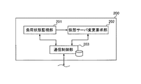
次に、モニターサーバ200の機能構成について、図11を参照して説明する。図11に示すように、本実施形態に係るモニターサーバ200は、負荷状態監視部201、仮想サーバ変更要求部202及び通信制御部203を含む。負荷状態監視部201は、通信制御部203による通信を介して、タスク管理サーバ300、ワーカーサーバ400及びタスク記憶サーバ500の負荷状態を監視している。
Next, the functional configuration of the
タスク管理サーバ300の負荷状態を監視する場合、負荷状態監視部201は、例えばタスク管理サーバ300を構成するプログラムを制御しているCPU、即ち演算装置の負荷状況や、ワーカーサーバ400を構成するプログラムを制御しているCPUの負荷状況や、タスク管理サーバ300が処理すべきものとしてタスク記憶サーバ500に記憶されているタスクの数を参照する。ワーカーサーバ400の負荷状況を監視する場合、負荷状態監視部201は、例えばワーカーサーバ400が処理すべきものとしてタスク記憶サーバ500に記憶されているタスクの数を参照する。タスク記憶サーバ500の負荷状況を監視する場合、負荷状態監視部201は、例えばタスク記憶サーバ500に割り当てられている記憶領域の空き領域等を参照する。
When monitoring the load state of the
負荷状態監視部201は、各サーバの負荷状態に対して設けられた閾値を記憶しており、上述した処理により監視している各サーバの負荷状態が、記憶している閾値を超えた場合、そのサーバが過負荷状態であると判断する。そして、負荷状態監視部201は、過負荷状態であると判断したサーバと同一の機能を担う仮想サーバ6の起動を決定し、仮想サーバ変更要求部202に通知する。
The load state monitoring unit 201 stores a threshold value provided for the load state of each server, and when the load state of each server monitored by the above-described processing exceeds the stored threshold value, Determine that the server is overloaded. Then, the load state monitoring unit 201 determines the activation of the virtual server 6 having the same function as the server that is determined to be in an overload state, and notifies the virtual server
また、負荷状態監視部201は、各サーバの負荷状態が低いと判断するための閾値を記憶しており、上述した処理により監視している各サーバの負荷状態が、上記閾値に基づいて低いと判断された場合、そのサーバの負荷が低いと判断する。そして、負荷状態監視部201は、負荷が低いと判断したサーバとして動作する仮想サーバの数を減らす、即ち、起動しているサーバを終了させることを決定し、仮想サーバ変更要求部202に通知する。
Further, the load state monitoring unit 201 stores a threshold value for determining that the load state of each server is low, and the load state of each server monitored by the above-described processing is low based on the above threshold value. If it is determined, it is determined that the load on the server is low. Then, the load state monitoring unit 201 determines to reduce the number of virtual servers operating as servers determined to have a low load, that is, to terminate the active server, and notifies the virtual server
仮想サーバ変更要求部202は、負荷状態監視部201からの上記通知に従い、通信制御部203を介して、上記過負荷状態であると判断された機能のサーバとして動作している仮想サーバ6の追加起動を、仮想管理サーバ4に対して要求する。また、仮想サーバ変更要求部202は、負荷状態監視部201からの上記通知に従い、通信制御部203を介して、負荷が低いと判断された機能のサーバとして動作している仮想サーバ6の終了を、仮想管理サーバ4に対して要求する。
The virtual server
尚、通信制御部203は、上記負荷状態の監視動作のために、図4に示す各サーバと通信する場合と、上記仮想サーバ6の起動若しくは終了を要求するために仮想管理サーバ4と通信する場合とがある。従って、通信制御部203は、上述した第1のDNS環境及び第2のDNS環境による通信手段、即ちホスト名とIPアドレスとの関連付け情報を含む。
The
次に、タスク管理サーバ300の機能構成について、図12を参照して説明する。図12に示すように本実施形態に係るタスク管理サーバ300は、タスク処理部301、画像処理部302及び通信制御部303を含む。タスク処理部301は、通信制御部303を介して入力されたタスクの種類に基づき、そのタスクを処理する。タスク処理部301によるタスク処理の態様としては、画像処理部302へのタスク入力、タスク記憶サーバ500へのタスク格納、公衆回線Dを介した画像処理装置3からのタスク処理進捗確認への応答等がある。
Next, the functional configuration of the
画像処理部302は、画像処理専用のサーバであるワーカーサーバ400に実行させるまでもない軽微な画像処理を実行する。画像処理部302が実行する画像処理としては、簡単な画像変換等である。通信制御部303は、モニターサーバ200の通信制御部203と同様に、第1のDNS環境及び第2のDNS環境による通信手段を有する。
The
次に、ワーカーサーバ400の機能構成について、図13を参照して説明する。図13に示すように本実施形態に係るワーカーサーバ400は、タスク取得部401、画像処理部402及び通信制御部403を含む。タスク取得部401は、通信制御部403を介してタスク記憶サーバ500に記憶されているタスクの取得を要求する。尚、本実施形態においては、タスク取得部401によるタスク取得要求も、ロードバランササーバ100によって振り分けられる。即ち、タスク取得部401は、通信制御部403を介して、ロードバランササーバ100に対してタスク要求を行う。
Next, the functional configuration of the
画像処理部402は、タスク取得部401が取得したタスク及び画像情報に基づき、画像処理を実行する。画像処理部402が実行する画像処理としては、例えばOCRや、情報埋め込み等、処理量の多い処理である。本実施形態に係るワーカーサーバ400は、入力されたタスクを処理するのではなく、タスク取得部401がタスク記憶サーバ500からタスクを取得し、画像処理部402がタスクを処理する。従って、タスク取得部401は、画像処理部402による画像処理が完了する度に、通信制御部403を介してタスク記憶サーバ500にアクセスし、タスクを取得する。尚、通信制御部403は、上記第1のDNS環境及び第2のDNS環境による通信手段を有する。
The
次に、タスク記憶サーバ500の機能構成について、図14を参照して説明する。図14に示すように、本実施形態に係るタスク記憶サーバ500は、タスク記憶部501及び通信制御部502を含む。タスク記憶部501は、タスク処理部301によってタスク記憶サーバ500に振り分けられたタスクや、そのタスクに係る画像情報が記憶されている記憶媒体である。通信制御部502は、上述した第1のDNS環境及び第2のDNS環境による通信手段を有する。
Next, the functional configuration of the
このような構成により、本実施形態に係る仮想サーバ管理システム及び画像処理システムが構成される。次に、本実施形態に係る画像処理システムの一般動作について、図15を参照して説明する。図15に示すように、まずは、ユーザが画像処理装置3を操作して、画像処理のジョブ及び処理すべき画像情報をロードバランササーバ100に送信する(S1501)。尚、本実施形態においては、例として、入力された画像のOCR(Optical Character Recognition)を実行する場合を例とする。
With such a configuration, the virtual server management system and the image processing system according to the present embodiment are configured. Next, a general operation of the image processing system according to the present embodiment will be described with reference to FIG. As shown in FIG. 15, first, the user operates the
ジョブ及び画像情報を受信したロードバランササーバ100においては、タスク振り分け部101が、上述したように、受信したジョブをタスクとして振り分け処理を実行し、振り分け先のタスク管理サーバ300にタスク及び画像情報を送信する(S1502)。ロードバランササーバ100からタスク及び画像情報を受信したタスク管理サーバ300においては、受信したタスク及び画像情報を、タスク処理部301がタスク記憶サーバ500に記憶させる(S1503)。即ち、タスク記憶サーバ500のタスク記憶部501が、実行命令記憶部として機能する。
In the
S1503の処理が完了した後、上述したように、ワーカーサーバ400のタスク取得部401が、ロードバランササーバ100にタスク要求を送信する(S1504)。タスク取得部401からタスク要求を受信したロードバランササーバ100は、そのタスク要求をタスク管理サーバ300に振り分ける(S1505)。タスク要求の振り分けを受けたタスク管理サーバ300は、タスク記憶サーバ500からタスク情報及び画像情報を取得し、ワーカーサーバ400に送信する(S1506)。
After the processing of S1503 is completed, as described above, the
タスク管理サーバ300からタスク情報及び画像情報を受信したワーカーサーバ400においては、画像処理部402がタスク、即ち本実施形態においてはOCRを実行し、その実行結果としての文字情報若しくは認識結果を含む情報(以降、文字情報等とする)の格納をロードバランササーバ100に要求する(S1507)。ワーカーサーバ400から実行結果の格納要求を受信したロードバランササーバ100は、上記格納要求をタスク管理サーバ300に振り分ける(S1508)。
In the
タスクの振り分けを受けたタスク管理サーバ300は、同時に受信した文字情報等を実行結果としてタスク記憶サーバ500のタスク記憶部501に記憶させる(S1509)。他方、S1501の処理の後、画像処理装置3は、ロードバランササーバ100を介して、送信したジョブの結果確認を所定期間毎に実行する(S1510)。S1509の処理の後に画像処理装置3からの結果確認(S1510)を受信すると、タスク管理サーバ300は、画像処理装置3に対して、結果確認への応答として実行結果である文字情報等の格納先、例えばURL(Uniform Resource Locator)を通知する。これにより、画像処理装置3を操作しているユーザが、タスク記憶サーバ500にアクセスして、実行結果である文字情報等を取得することが可能となる。
The
このような画像処理装置において、上述したように、モニターサーバ200がタスク管理サーバ300、ワーカーサーバ400及びタスク記憶サーバ500の負荷状態を監視しており、状況に応じて夫々のサーバとして動作する仮想サーバ6の数の増減が行われる。ここで、図15において説明したように、各サーバは互いに通信しながら処理を行っているため、サーバの数が変化すると、DNSの情報、具体的には、図10において説明したような情報を、変化したサーバの数に応じて更新する必要がある。このDNS情報の更新の仕組みが、本実施形態に係る要旨である。
In such an image processing apparatus, as described above, the
図16を参照して、本実施形態に係るDNS情報の更新動作について説明する。図16においては、モニターサーバが、タスク管理サーバ300が過負荷状態であることを判断した場合を例として説明する。また、図16の説明においては、DNS情報を更新する対象としてロードバランササーバ100を例として説明するが、他のモニターサーバ200、タスク管理サーバ300、ワーカーサーバ400及びタスク記憶サーバ500も同様である。
With reference to FIG. 16, the update operation of the DNS information according to the present embodiment will be described. In FIG. 16, a case where the monitor server determines that the
図16に示すように、まず、モニターサーバ200の仮想サーバ変更要求部202が、仮想管理サーバ4に対して、タスク管理サーバ300としての、仮想サーバ6の起動要求を送信する(S1601)。即ち、モニターサーバ200の仮想サーバ変更要求部202が、仮想サーバ起動要求部として機能する。起動要求を受信した仮想管理サーバ4においては、仮想サーバ起動管理部4aが上述した処理を実行して、タスク管理サーバ300としての仮想サーバ6を新たに起動させる(S1602)。即ち、仮想管理サーバ4の仮想サーバ起動管理部4aが、仮想サーバ管理部として機能する。これにより、新たに起動された仮想サーバ6に対して、図6において説明したように、識別子及びIPアドレスが設定され、仮想サーバ情報記憶部4bに記憶される。
As shown in FIG. 16, first, the virtual server
図6に示す状態において、上記識別子及びIPアドレスの設定が実行された後の仮想サーバ情報記憶部4bに記憶されている情報の例を図17に示す。図17に示す例においては、新たな識別子として“i−0004”が設定され、新たなIPアドレスとして“10.0.1.4”が設定されている。このように、S1602の処理が完了すると、仮想管理サーバ4は、モニターサーバ200に対して、上記新たに設定した情報を通知する(S1603)。
FIG. 17 shows an example of information stored in the virtual server
S1603の通知を受けることにより、新たに起動された仮想サーバ6の識別子を取得したモニターサーバ200は、その識別子である“i−0004”という情報及び新たな仮想サーバ6がタスク管理サーバ300として起動されたことを示す機能識別情報である“taskmaster”という情報をデータベースサーバ5に登録する(S1604)。これにより、新たに起動された仮想サーバ6の識別子と、その機能を示す情報が図18に示すように関連付けて登録される。即ち、データベースサーバ5のサーバ機能情報記憶部5bが、仮想サーバ機能管理部として機能する。
Upon receiving the notification of S1603, the
S1604の登録が完了すると、モニターサーバ200は、DNS情報を更新させる対象であるロードバランササーバ100に対して、DNS情報の更新要求を送信する(S1605)。S1605の更新要求を受信したロードバランササーバ100においては、通信制御部102が、まず仮想管理サーバ4にアクセスし、仮想サーバ情報記憶部4bに記憶されている全仮想サーバ6の情報、即ち、図18に示す情報を取得する(S1606)。
When the registration in S1604 is completed, the
S1606の処理により、全仮想サーバ6の情報を取得すると、通信制御部102は、次に、夫々の仮想サーバ6の識別子に基づき、データベースサーバ5にアクセスして、夫々の仮想サーバ6の機能を識別する機能識別情報を取得する(S1607)。S1607の処理により、機能識別情報を取得すると、通信制御部102は、S1606において取得したIPアドレスとS1607において取得した機能識別情報を対応させて、夫々の希望別にIPアドレスを分類し、予め登録されている登録済みホスト名を、夫々の機能別にIPアドレスに関連付けることによってDNS情報を更新する(S1608)。換言すると、通信制御部102は、S1607において取得した機能識別情報に従い、S1606において取得したIPアドレスを、仮想サーバ6の機能別に予め定められたホスト名に関連付ける。
When the information of all the virtual servers 6 is acquired by the processing of S1606, the
図16の例においては、DNS情報として図10において説明したような情報が保持されている状態において、タスク管理サーバ300が1つ増えた場合を例としている。従って、S1608の処理の結果、図10に示すような状態であったDNS情報は、図19に示すような状態に更新される。図16の処理の結果、タスク管理サーバ300として動作する仮想サーバ6のIPアドレスとして、元から存在した“10.0.1.1”に加えて、新たに“10.0.1.4”が追加された。従って、図19に示す例においては、登録済みホスト名である“taskmaster00”、“taskmaster01”、・・・に対して、“10.0.1.1”と“10.0.1.4”とが交互に割り当てられている。これにより、ロードバランササーバ100は、タスク管理サーバ300が追加される前と同様に、登録済みホスト名の順番に従ってタスクの割り振りを実行するだけで、2つのタスク管理サーバ300に交互にタスクが割り振られることとなる。このような処理により、本実施形態に係るDNS情報の更新動作が完了する。
In the example of FIG. 16, the case where the
尚、上述したように、図16の例においては、ロードバランササーバ100が、DNS情報を更新する場合を例として説明したが、モニターサーバ200、タスク管理サーバ300、ワーカーサーバ400及びタスク記憶サーバ500も同様である。DNS情報を更新する全てのサーバが、S1608において同一のルールに従ってDNS情報を更新することにより、全てのサーバにおけるDNS情報の更新結果が同一となる。
Note that, as described above, in the example of FIG. 16, the
例えば、OCR等のワーカーサーバ400において処理されるタスクが集中し、ワーカーサーバ400の負荷が高くなった場合、タスク記憶サーバ500に未処理のタスク情報が蓄積される。モニターサーバ200は、タスク記憶サーバ500に蓄積されたタスク情報の量に応じてワーカーサーバ400の過負荷を判断し、ワーカーサーバ400として機能する仮想サーバ6の追加起動を要求する。これにより、図16の処理が実行され、ワーカーサーバ400として機能する仮想サーバ6が追加され、ワーカーサーバ400の過負荷状態が解消される。尚、ワーカーサーバ400に実行させる画像処理の例を図20に示す。
For example, when tasks processed in the
以上説明したように、本実施形態に係る仮想サーバ管理システムにより、仮想サーバが増減された場合に増減された仮想サーバの機能を把握し、予め定められたホスト名のリストに従ってホスト名を付与して通信を行うことが可能となる。これにより、仮想サーバにおいてタスクを振り分けるロードバランササーバ100は、予め定められたホスト名、即ち、タスク振り分け機能を実現するプログラム内に組み込まれたホスト名のリストに従ってタスクの振り分けを実行することができるため、タスクの振り分けに際して別途記憶されたホスト名のリストを参照する必要がなく、タスクの振り分けを迅速に行うことができる。
As described above, the virtual server management system according to the present embodiment grasps the function of the virtual server that is increased or decreased when the virtual server is increased or decreased, and assigns the host name according to a predetermined list of host names. Communication. As a result, the
尚、上記実施形態においては、ロードバランササーバ100、モニターサーバ200、タスク管理サーバ300、ワーカーサーバ400及びタスク記憶サーバ500夫々に含まれる通信制御部が、図10及び図19に示すような情報を保持している場合を例として説明したが、仮想サーバ6によってDNSサーバを構築し、そのDNSサーバが、図10及び図19に示すような情報を管理することも可能である。この場合、ロードバランササーバ100、モニターサーバ200、タスク管理サーバ300、ワーカーサーバ400及びタスク記憶サーバ500に含まれる通信制御部は、上記DNSサーバにアクセスすることによってホスト名の名前解決を行うこの場合においても、ロードバランササーバ100が、プログラムとして組み込まれているホスト名に従ってタスクの割り振りを実行し、上記DNSサーバが、上記組み込まれているホスト名のリストに従ってDNS情報を管理することにより、上記と同様の効果を得ることができる。
In the above embodiment, the communication control unit included in each of the
また、図16の説明においては、モニターサーバ200が、データベースサーバ5に識別情報及び機能識別情報を登録すると共に、ロードバランササーバ100に対してDNS情報の更新要求を送信し、この更新要求に応じて、ロードバランササーバ100が、仮想管理サーバ4及びデータベースサーバ5から情報を取得する場合を例として説明した。この場合、DNS情報を更新するのは、ロードバランササーバ100だけではないので、モニターサーバ200は、多くの宛先に対して更新要求を送信する必要がある。これに対して、モニターサーバ200が更新要求を送信するのではなく、ロードバランササーバ100が定期的に仮想管理サーバ4及びデータベースサーバ5から情報を取得し、DNS情報の更新処理を実行するようにしても良い。これにより、モニターサーバ200の処理負荷を低減することができる。
In the description of FIG. 16, the
1 物理サーバ、
2 クライアント端末、
3 画像処理装置、
4 仮想管理サーバ、
4a 仮想サーバ起動管理部、
4b 仮想サーバ情報記憶部、
4c 通信制御部、
5 データベースサーバ、
5a 通信制御部、
5b サーバ機能情報記憶部、
6 仮想サーバ、
10 CPU、
20 RAM、
30 ROM、
40 HDD、
50 I/F、
60 LCD、
70 操作部、
80 バス、
100 ロードバランササーバ、
101 タスク振り分け部、
102 通信制御部、
200 モニターサーバ、
201 負荷状態監視部、
202 仮想サーバ変更要求部、
203 通信制御部、
300 タスク管理サーバ、
301 タスク処理部、
302 画像処理部、
303 通信制御部、
400 ワーカーサーバ、
401 タスク取得部、
402 画像処理部、
403 通信制御部、
500 タスク記憶サーバ、
501 タスク記憶部、
502 通信制御部
1 physical server,
2 client terminals,
3 image processing device,
4 virtual management server,
4a virtual server activation management unit,
4b virtual server information storage unit,
4c communication control unit,
5 Database server,
5a communication control unit,
5b Server function information storage unit,
6 virtual servers,
10 CPU,
20 RAM,
30 ROM,
40 HDD,
50 I / F,
60 LCD,
70 operation unit,
80 bus,
100 load balancer server,
101 Task distribution part,
102 communication control unit,
200 monitor server,
201 load state monitoring unit,
202 Virtual server change request section,
203 communication control unit,
300 task management server,
301 task processing unit,
302 image processing unit,
303 communication control unit,
400 worker servers,
401 task acquisition unit,
402 image processing unit,
403 communication control unit,
500 task storage server,
501 task storage unit,
502 communication control unit
Claims (15)
前記仮想サーバ管理部に対して前記ネットワーク上において起動している仮想サーバの負荷状態に応じて仮想サーバの起動を要求する仮想サーバ起動要求部と、
前記仮想サーバの機能の情報を、前記識別情報と関連付けて記憶している仮想サーバ機能管理部と、
前記仮想サーバの機能別に予め定められたホスト名のリストに従って前記仮想サーバのネットワークアドレスと前記ホスト名との対応関係を管理する通信制御部とを含む仮想サーバ管理システムであって、
前記仮想サーバ管理部が、前記仮想サーバ起動要求部からの要求に応じて前記識別情報及び前記仮想サーバのネットワークアドレスを新たに設定して仮想サーバを新たに起動し且つ前記設定した識別情報及び前記ネットワークアドレスを前記仮想サーバ起動要求部に送信すると共に、前記通信制御部からの要求に応じて記憶している識別情報及びネットワークアドレスを送信し、
前記仮想サーバ起動要求部が、前記仮想サーバの起動によって受信した前記識別情報及び前記仮想サーバに担わせる機能の情報を前記仮想サーバ機能管理部に記憶させ、
前記仮想サーバ機能管理部が、前記通信制御部からの要求に応じて、起動されている前記仮想サーバの機能の情報を前記通信制御部に送信し、
前記通信制御部が、前記仮想サーバ管理部から前記記憶されている識別情報及びネットワークアドレスを取得し、前記仮想サーバ機能管理部から前記仮想サーバの機能の情報を取得し、前記取得したネットワークアドレスを前記取得した仮想サーバの機能の情報に従って前記仮想サーバの機能別に予め定められたホスト名に関連付けて記憶することを特徴とする仮想サーバ管理システム。 And virtual server management unit which manages by storing virtual server configured by an information processing apparatus connected to the network, in association with the network address of the virtual server identification information for identifying the virtual server,
A virtual server activation request unit that requests the virtual server management unit to activate a virtual server according to a load state of a virtual server activated on the network;
A virtual server function management unit storing information on the function of the virtual server in association with the identification information;
A virtual server management system including a communication control unit that manages a correspondence relationship between a network address of the virtual server and the host name according to a list of host names predetermined for each function of the virtual server,
In response to a request from the virtual server activation request unit, the virtual server management unit newly sets the identification information and the network address of the virtual server to newly start a virtual server, and the set identification information and the Sending the network address to the virtual server activation request unit, sending the stored identification information and network address in response to a request from the communication control unit,
The virtual server activation request unit stores the identification information received by the activation of the virtual server and information on functions to be assigned to the virtual server in the virtual server function management unit,
In response to a request from the communication control unit, the virtual server function management unit transmits information on the function of the activated virtual server to the communication control unit,
The communication control unit acquires the stored identification information and network address from the virtual server management unit, acquires function information of the virtual server from the virtual server function management unit, and acquires the acquired network address. A virtual server management system, wherein the virtual server management system stores information in association with a host name predetermined for each function of the virtual server in accordance with the acquired function information of the virtual server.
前記通信制御部が、前記更新要求に応じて、前記仮想サーバ管理部から前記記憶されている識別情報及びネットワークアドレスを取得し、前記仮想サーバ機能管理部から前記仮想サーバの機能の情報を取得することを特徴とする、請求項1に記載の仮想サーバ管理システム。 The virtual server activation request unit stores the identification information and the function information received by activation of the virtual server in the virtual server function management unit, and the communication control unit causes the network address and host name of the virtual server to be stored. Send a request to update the correspondence with
In response to the update request, the communication control unit acquires the stored identification information and network address from the virtual server management unit, and acquires information on the function of the virtual server from the virtual server function management unit. The virtual server management system according to claim 1, wherein:
前記実行命令割り振り部は、前記予め定められたホスト名に従って前記実行命令を割り振ることを特徴とする請求項1乃至6に記載の仮想サーバ管理システム。 An execution instruction allocating unit that acquires an execution instruction of information processing that can be processed by the function realized by the virtual server, and that allocates the acquired execution instruction to any of a plurality of virtual servers,
The virtual server management system according to claim 1, wherein the execution instruction allocation unit allocates the execution instruction according to the predetermined host name.
前記実行命令割り振り部によって割り振られた前記実行命令の情報を記憶する実行命令記憶部と、
前記記憶された実行命令の情報を取得して前記実行命令に係る情報処理としての画像処理を実行する画像処理部とを含むことを特徴とする画像処理システム。 An image processing system configured by the virtual server management system according to claim 7,
An execution instruction storage unit that stores information on the execution instructions allocated by the execution instruction allocation unit;
An image processing system comprising: an image processing unit that acquires information on the stored execution instruction and executes image processing as information processing related to the execution instruction.
前記仮想サーバの機能別に予め定められたホスト名のリストに従って前記仮想サーバのネットワークアドレスと前記ホスト名との対応関係を管理し、前記ネットワーク上の通信を制御する通信制御部と、
前記仮想サーバを識別する識別情報と前記仮想サーバのネットワークアドレスを関連付けて記憶している仮想サーバ管理部から前記記憶されている識別情報及びネットワークアドレスを取得すると共に、前記仮想サーバの機能の情報を前記識別情報と関連付けて記憶している仮想サーバ機能管理部から前記仮想サーバの機能の情報を取得する情報取得部と、
前記取得したネットワークアドレスを前記取得した仮想サーバの機能の情報に従って前記仮想サーバの機能別に予め定められたホスト名に関連付けて記憶することにより前記仮想サーバのネットワークアドレスと前記ホスト名との対応関係を更新する情報更新部とを含むことを特徴とする仮想サーバ制御装置。 A virtual server control device that controls a virtual server configured by information processing devices connected to a network,
A communication control unit that manages the correspondence between the network address of the virtual server and the host name according to a list of host names predetermined for each function of the virtual server, and controls communication on the network;
Obtaining the stored identification information and network address from the virtual server management unit that stores the identification information for identifying the virtual server and the network address of the virtual server in association with each other, and the function information of the virtual server An information acquisition unit for acquiring information on the function of the virtual server from a virtual server function management unit stored in association with the identification information;
The correspondence between the network address of the virtual server and the host name is stored by associating and storing the acquired network address in association with a predetermined host name for each function of the virtual server according to the information of the function of the acquired virtual server. A virtual server control device comprising: an information updating unit for updating.
前記仮想サーバの機能別に予め定められたホスト名のリストに従って前記仮想サーバのネットワークアドレスと前記ホスト名との対応関係を管理し、前記ネットワーク上の通信を制御するステップと、
前記仮想サーバを識別する識別情報と前記仮想サーバのネットワークアドレスを関連付けて記憶している仮想サーバ管理部から前記記憶されている識別情報及びネットワークアドレスを取得すると共に、前記仮想サーバの機能の情報を前記識別情報と関連付けて記憶している仮想サーバ機能管理部から前記仮想サーバの機能の情報を取得するステップと、
前記取得したネットワークアドレスを前記取得した仮想サーバの機能の情報に従って前記仮想サーバの機能別に予め定められたホスト名に関連付けて記憶することにより、前記仮想サーバのネットワークアドレスと前記ホスト名との対応関係を更新するステップとを前記情報処理装置に実行させることを特徴とする制御プログラム。 A control program that causes an information processing device to function as a virtual server control device that controls a virtual server configured by an information processing device connected to a network,
Managing the correspondence between the network address of the virtual server and the host name according to a list of host names predetermined for each function of the virtual server, and controlling communication on the network;
Obtaining the stored identification information and network address from the virtual server management unit that stores the identification information for identifying the virtual server and the network address of the virtual server in association with each other, and the function information of the virtual server Obtaining information on the function of the virtual server from the virtual server function management unit stored in association with the identification information;
Correspondence between the network address of the virtual server and the host name by storing the acquired network address in association with a host name predetermined for each function of the virtual server according to the function information of the acquired virtual server And a step of updating the information processing apparatus.
Priority Applications (1)
| Application Number | Priority Date | Filing Date | Title |
|---|---|---|---|
| JP2009210613A JP5287623B2 (en) | 2009-09-11 | 2009-09-11 | Virtual server management system, image processing system, virtual server management apparatus, and control program |
Applications Claiming Priority (1)
| Application Number | Priority Date | Filing Date | Title |
|---|---|---|---|
| JP2009210613A JP5287623B2 (en) | 2009-09-11 | 2009-09-11 | Virtual server management system, image processing system, virtual server management apparatus, and control program |
Publications (3)
| Publication Number | Publication Date |
|---|---|
| JP2011061608A JP2011061608A (en) | 2011-03-24 |
| JP2011061608A5 JP2011061608A5 (en) | 2012-07-26 |
| JP5287623B2 true JP5287623B2 (en) | 2013-09-11 |
Family
ID=43948715
Family Applications (1)
| Application Number | Title | Priority Date | Filing Date |
|---|---|---|---|
| JP2009210613A Expired - Fee Related JP5287623B2 (en) | 2009-09-11 | 2009-09-11 | Virtual server management system, image processing system, virtual server management apparatus, and control program |
Country Status (1)
| Country | Link |
|---|---|
| JP (1) | JP5287623B2 (en) |
Families Citing this family (4)
| Publication number | Priority date | Publication date | Assignee | Title |
|---|---|---|---|---|
| JP5039226B1 (en) * | 2011-05-31 | 2012-10-03 | 株式会社東芝 | Server and data distribution system |
| JP5808700B2 (en) * | 2012-03-05 | 2015-11-10 | 株式会社Nttドコモ | Communication control device, communication control system, virtualization server management device, switch device, and communication control method |
| KR102035071B1 (en) * | 2012-05-25 | 2019-11-08 | 삼성에스디에스 주식회사 | System and method for constructing on-demand virtual cluster |
| JP5997659B2 (en) * | 2013-05-09 | 2016-09-28 | 日本電信電話株式会社 | Distributed processing system and distributed processing method |
Family Cites Families (6)
| Publication number | Priority date | Publication date | Assignee | Title |
|---|---|---|---|---|
| JP3417374B2 (en) * | 2000-02-04 | 2003-06-16 | 日本電気株式会社 | Server, client, client server system, load distribution method, recording medium |
| JP4544146B2 (en) * | 2005-11-29 | 2010-09-15 | 株式会社日立製作所 | Disaster recovery method |
| JP4739272B2 (en) * | 2007-04-19 | 2011-08-03 | 株式会社富士通アドバンストエンジニアリング | Load distribution apparatus, virtual server management system, load distribution method, and load distribution program |
| JP2009116380A (en) * | 2007-11-01 | 2009-05-28 | Nec Corp | Virtual server movement controller, virtual server movement control method and program |
| WO2009098909A1 (en) * | 2008-02-04 | 2009-08-13 | Nec Corporation | Virtual appliance assignment system |
| JP5423401B2 (en) * | 2008-02-22 | 2014-02-19 | 日本電気株式会社 | Information processing apparatus, information processing system, setting program transmission method, and server setting program |
-
2009
- 2009-09-11 JP JP2009210613A patent/JP5287623B2/en not_active Expired - Fee Related
Also Published As
| Publication number | Publication date |
|---|---|
| JP2011061608A (en) | 2011-03-24 |
Similar Documents
| Publication | Publication Date | Title |
|---|---|---|
| JP5582344B2 (en) | Connection management system and connection management server linkage method in thin client system | |
| US7454482B2 (en) | Print queue manager | |
| US8321530B2 (en) | Cloud computing system, server computer, device connection method, and storage medium | |
| JP5557689B2 (en) | Network system | |
| JP4787684B2 (en) | Session management system, session management method, and program | |
| JP4311636B2 (en) | A computer system that shares a storage device among multiple computers | |
| JP4960782B2 (en) | Information processing apparatus and method and program for controlling the same | |
| JP4677482B2 (en) | Access distribution system, server device, common management device, access distribution device, access distribution method, and computer program | |
| JP5174747B2 (en) | Computer system and management device | |
| JP6205878B2 (en) | Data processing apparatus, system and program | |
| JP5352367B2 (en) | Virtual machine boot terminal and virtual machine boot program | |
| JP5459983B2 (en) | Information processing apparatus, information processing apparatus control method, and computer program | |
| US20180176289A1 (en) | Information processing device, information processing system, computer-readable recording medium, and information processing method | |
| JP2006285316A (en) | Server performance measuring method, server performance measuring system and computer program used for the method and system | |
| JP2019032686A (en) | Managing device, control method for managing device, and program | |
| JP5287623B2 (en) | Virtual server management system, image processing system, virtual server management apparatus, and control program | |
| JP2016218530A (en) | Request distribution system, management system, and control method thereof | |
| JP2007004403A (en) | Distributed resource allocation system, distributed resource allocation method, and program | |
| JP2013105237A (en) | Job processing system, job processing device, load distributing device, job processing program, and load distributing program | |
| JPWO2022132317A5 (en) | ||
| JP5524606B2 (en) | Communication method between modules in virtual environment, information processing apparatus and control method thereof, client apparatus, information processing system, and program | |
| JP2016177324A (en) | Information processing apparatus, information processing system, information processing method, and program | |
| US9250841B2 (en) | Print server, control method of print server, and storage medium | |
| JP6812673B2 (en) | Image processing systems, image forming equipment, data sharing methods, and computer programs | |
| JP5554946B2 (en) | Thin client system, session management method, and program |
Legal Events
| Date | Code | Title | Description |
|---|---|---|---|
| A521 | Written amendment |
Free format text: JAPANESE INTERMEDIATE CODE: A523 Effective date: 20120613 |
|
| A621 | Written request for application examination |
Free format text: JAPANESE INTERMEDIATE CODE: A621 Effective date: 20120613 |
|
| A977 | Report on retrieval |
Free format text: JAPANESE INTERMEDIATE CODE: A971007 Effective date: 20130311 |
|
| TRDD | Decision of grant or rejection written | ||
| A01 | Written decision to grant a patent or to grant a registration (utility model) |
Free format text: JAPANESE INTERMEDIATE CODE: A01 Effective date: 20130507 |
|
| A61 | First payment of annual fees (during grant procedure) |
Free format text: JAPANESE INTERMEDIATE CODE: A61 Effective date: 20130520 |
|
| R151 | Written notification of patent or utility model registration |
Ref document number: 5287623 Country of ref document: JP Free format text: JAPANESE INTERMEDIATE CODE: R151 |
|
| LAPS | Cancellation because of no payment of annual fees |