JP5287386B2 - Game machine - Google Patents

Game machine Download PDF

Info

Publication number
JP5287386B2
JP5287386B2 JP2009062211A JP2009062211A JP5287386B2 JP 5287386 B2 JP5287386 B2 JP 5287386B2 JP 2009062211 A JP2009062211 A JP 2009062211A JP 2009062211 A JP2009062211 A JP 2009062211A JP 5287386 B2 JP5287386 B2 JP 5287386B2
Authority
JP
Japan
Prior art keywords
door body
locking
hook
frame
portions
Prior art date
Legal status (The legal status is an assumption and is not a legal conclusion. Google has not performed a legal analysis and makes no representation as to the accuracy of the status listed.)
Active
Application number
JP2009062211A
Other languages
Japanese (ja)
Other versions
JP2010213810A (en
JP2010213810A5 (en
Inventor
誠 中村
Current Assignee (The listed assignees may be inaccurate. Google has not performed a legal analysis and makes no representation or warranty as to the accuracy of the list.)
Sanyo Bussan Co Ltd
Original Assignee
Sanyo Bussan Co Ltd
Priority date (The priority date is an assumption and is not a legal conclusion. Google has not performed a legal analysis and makes no representation as to the accuracy of the date listed.)
Filing date
Publication date
Application filed by Sanyo Bussan Co Ltd filed Critical Sanyo Bussan Co Ltd
Priority to JP2009062211A priority Critical patent/JP5287386B2/en
Publication of JP2010213810A publication Critical patent/JP2010213810A/en
Publication of JP2010213810A5 publication Critical patent/JP2010213810A5/ja
Application granted granted Critical
Publication of JP5287386B2 publication Critical patent/JP5287386B2/en
Active legal-status Critical Current
Anticipated expiration legal-status Critical

Links

Images

Description

本発明は、パチンコ機等の遊技機に関するものである。   The present invention relates to a gaming machine such as a pachinko machine.

一般にパチンコ機等の遊技機では、メンテナンス等の観点から遊技機本体が固定枠に対し開閉可能に設けられている。そのため、店員以外の者が無断で遊技機本体を開放できないように、遊技機には施錠装置が設けられている。かかる施錠装置としては、専用の鍵を用いて操作されるシリンダ錠と、固定枠に設けられた複数の被係合部に対しそれぞれ係脱可能に設けられた複数の鉤部材と、鍵によるシリンダ錠の解錠操作に応じて複数の鉤部材を連動させる伝達機構とを備えたものが知られている。そして、施錠状態では各鉤部材がそれぞれ対応する被係合部に係合することで遊技機本体が固定枠に対し開放不能となる。他方、専用の鍵でシリンダ錠を解錠操作することにより伝達機構を介して各鉤部材が被係合部から同時に離脱し、遊技機本体が開放可能となる(例えば特許文献1参照)。   Generally, in gaming machines such as pachinko machines, a gaming machine main body is provided so as to be openable and closable with respect to a fixed frame from the viewpoint of maintenance and the like. Therefore, the gaming machine is provided with a locking device so that a person other than the store clerk cannot open the gaming machine body without permission. Such a locking device includes a cylinder lock that is operated using a dedicated key, a plurality of hook members that can be engaged with and disengaged from a plurality of engaged portions that are provided on a fixed frame, and a cylinder that uses a key. There has been known one provided with a transmission mechanism for interlocking a plurality of scissors members according to an unlocking operation of the lock. And in the locked state, each gutter member engages with the corresponding engaged portion, so that the gaming machine main body cannot be opened with respect to the fixed frame. On the other hand, when the cylinder lock is unlocked with a dedicated key, the hook members are simultaneously detached from the engaged portions via the transmission mechanism, and the gaming machine main body can be opened (see, for example, Patent Document 1).

近年、遊技ホールでは、営業中に遊技機本体を不正に解錠し、本体裏側に設けられた制御機器を不正に操作したり交換する等して、多くの遊技媒体を獲得する不正行為が行われることもある。このような不正解錠は、通常、遊技機本体と固定枠との隙間から針金等の線材を差込み、当該線材を鉤部材、シリンダ錠のカム板、伝達機構などに引っ掛けて解錠方向に動かすことにより行われる。鉤部材等に対して不正な解錠操作が行われると、鉤部材が被係合部から離脱し、遊技機本体が開放可能となる。   In recent years, gaming halls have been used for illegal activities to acquire a large number of gaming media by illegally unlocking the gaming machine body during operation and illegally operating or exchanging control devices provided on the back side of the gaming machine. Sometimes it is. Such unauthorized unlocking is usually performed by inserting a wire such as a wire from the gap between the gaming machine main body and the fixed frame and hooking the wire to a hook member, a cylinder lock cam plate, a transmission mechanism or the like to move in the unlocking direction. Is done. When an unauthorized unlocking operation is performed on the heel member or the like, the heel member is detached from the engaged portion, and the gaming machine main body can be opened.

特開2004−024337号公報JP 2004-024337 A

しかしながら、従来、施錠装置は、遊技機本体の背面側に設けられており、鉤部材、シリンダ錠のカム板、伝達機構など線材等を引っ掛けやすい各種機構が背面側に露出した状態となっている。そのため、遊技機本体と固定枠との隙間から針金等の線材を差込み、遊技機本体を不正に開放するといった不正行為が比較的容易に行われるおそれがあった。   However, conventionally, the locking device is provided on the back side of the gaming machine body, and various mechanisms that are easy to hook a wire member such as a hook member, a cylinder lock cam plate, and a transmission mechanism are exposed on the back side. . For this reason, there has been a risk that a fraudulent act such as inserting a wire such as a wire from the gap between the gaming machine main body and the fixed frame and illegally opening the gaming machine main body may be performed relatively easily.

本発明は、上記例示した問題点などを解決するためになされたものであり、その目的は、線材等を用いた不正解錠に対する防御性能に優れた遊技機を提供することにある。   The present invention has been made to solve the above-described problems and the like, and an object of the present invention is to provide a gaming machine excellent in defense performance against unauthorized unlocking using a wire or the like.

上記の目的を達成するため、本発明に係る遊技機は、
支持体に対し開閉可能に支持された第1扉体と、
前記第1扉体の前面側にて当該第1扉体に対し開閉可能に支持された第2扉体と、
前記支持体に対し前記第1扉体を施錠しかつ前記第1扉体に対し前記第2扉体を施錠するための施錠装置とを備えた遊技機であって、
前記施錠装置は、
前記第2扉体の閉状態において当該第2扉体と前記第1扉体との間に形成される収容空間に配置されるとともに、
前記第1扉体に固定される基枠部材と、
前記基枠部材に固定されるとともに、前記第2扉体の閉状態において当該第2扉体の前面から所定の鍵により操作可能な錠部材と、
前記支持体に固定された第1鉤部と係合可能な第1鉤受部が前記基枠部材に対して相対変位可能に設けられ、前記第1扉体に形成された挿通孔を介して前記収容空間内へ進入した前記第1鉤部が前記第1鉤受部に係合して前記第1扉体の開放を規制する施錠状態から、前記第1鉤部が前記第1鉤受部から係合解除され前記第1扉体の開放を許容する解錠状態へ、少なくとも前記鍵による第1操作に応じた前記錠部材の動作に連動して切換わる第1施錠機構と、
前記第2扉体に固定された第2鉤部と係合可能な第2鉤受部が前記基枠部材に対して相対変位可能に設けられ、前記第2鉤部が前記第2鉤受部に係合して前記第2扉体の開放を規制する施錠状態から、前記第2鉤部が前記第2鉤受部から係合解除され前記第2扉体の開放を許容する解錠状態へ、少なくとも前記鍵による第2操作に応じた前記錠部材の動作に連動して切換わる第2施錠機構とを備えたことをその要旨としている。
In order to achieve the above object, a gaming machine according to the present invention provides:
A first door supported to be openable and closable with respect to the support;
A second door body supported on the front side of the first door body so as to be openable and closable with respect to the first door body;
A gaming machine comprising: a locking device for locking the first door to the support and locking the second door to the first door;
The locking device is
In the closed state of the second door body and disposed in the accommodating space formed between the second door body and the first door body,
A base frame member fixed to the first door body;
A locking member fixed to the base frame member and operable with a predetermined key from the front surface of the second door body in the closed state of the second door body;
A first hook receiving portion that is engageable with the first hook portion fixed to the support body is provided so as to be relatively displaceable with respect to the base frame member, and through an insertion hole formed in the first door body. From the locked state in which the first hook part that has entered the housing space engages with the first hook receiving part to restrict the opening of the first door body, the first hook part is the first hook receiving part. A first locking mechanism that switches to an unlocked state that is disengaged from the door and allows the first door body to be opened at least in conjunction with the operation of the locking member according to the first operation by the key;
A second hook receiving portion engageable with a second hook portion fixed to the second door body is provided so as to be relatively displaceable with respect to the base frame member, and the second hook portion is the second hook receiving portion. From the locked state in which the opening of the second door body is restricted by engaging the door, the unlocked state in which the second hook part is disengaged from the second hook receiving part and the second door body is allowed to open. The gist of the invention is that it comprises a second locking mechanism that switches in conjunction with at least the operation of the locking member in response to a second operation by the key.

本発明の遊技機によれば、不正解錠に対する防御性能の向上等を図るという優れた効果を奏する。   According to the gaming machine of the present invention, there is an excellent effect of improving the defense performance against unauthorized unlocking.

一実施形態におけるパチンコ機を示す正面図である。It is a front view which shows the pachinko machine in one Embodiment. パチンコ機の斜視図である。It is a perspective view of a pachinko machine. 内枠及び遊技盤の構成を示す正面図である。It is a front view which shows the structure of an inner frame and a game board. 内枠の構成を示す背面図であるIt is a rear view which shows the structure of an inner frame. パチンコ機の構成を示す背面図である。It is a rear view which shows the structure of a pachinko machine. 電気的構成を示すブロック図である。It is a block diagram which shows an electric structure. 施錠装置、外枠、内枠及び前面枠などの各部材を示す分解斜視図である。It is a disassembled perspective view which shows each member, such as a locking device, an outer frame, an inner frame, and a front frame. 施錠装置、外枠、内枠及び前面枠などの各部材を組み付けた状態を示す斜視図である。It is a perspective view which shows the state which assembled | attached each member, such as a locking device, an outer frame, an inner frame, and a front frame. 施錠装置、外枠、内枠及び前面枠などの各部材を組み付けた状態で、前面枠を開放した状態を示す斜視図である。It is a perspective view which shows the state which open | released the front frame in the state which assembled | attached each member, such as a locking device, an outer frame, an inner frame, and a front frame. 施錠装置、外枠、内枠及び前面枠などの各部材を組み付けた状態で、前面枠及び内枠を開放した状態を示す斜視図である。It is a perspective view which shows the state which open | released the front frame and the inner frame in the state which assembled | attached each member, such as a locking device, an outer frame, an inner frame, and a front frame. 施錠装置を正面左側から見た斜視図である。It is the perspective view which looked at the locking device from the front left side. 施錠装置を正面右側から見た斜視図である。It is the perspective view which looked at the locking device from the front right side. 施錠装置を背面左側から見た斜視図である。It is the perspective view which looked at the locking device from the back left side. 施錠装置を背面右側から見た斜視図である。It is the perspective view which looked at the locking device from the back right side. 施錠装置の正面図である。It is a front view of a locking device. 施錠装置の左側面図である。It is a left view of a locking device. 施錠装置の右側面図である。It is a right view of a locking device. 施錠装置の背面図である。It is a rear view of a locking device. 施錠装置の分解図である。It is an exploded view of a locking device. (a)は、第1摺動杆が上方へ摺動した状態における施錠装置の背面図であり、(b)は、その状態における施錠装置の右側面図である。(A) is a rear view of the locking device in a state where the first sliding rod is slid upward, and (b) is a right side view of the locking device in that state. (a)は、第2摺動杆が下方へ摺動した状態における施錠装置の背面図であり、(b)は、その状態における施錠装置の右側面図である。(A) is a rear view of the locking device in a state where the second sliding rod slides downward, and (b) is a right side view of the locking device in that state. (a)は、第1摺動杆が上方へ摺動した状態における施錠装置を正面右側から見た斜視図であり、(b)は、その状態における施錠装置を背面左側から見た斜視図である。(A) is the perspective view which looked at the locking device in the state which the 1st sliding rod slid upwards from the front right side, (b) is the perspective view which looked at the locking device in the state from the back left side. is there. (a)は、第2摺動杆が下方へ摺動した状態における施錠装置を正面右側から見た斜視図であり、(b)は、その状態における施錠装置を背面左側から見た斜視図である。(A) is the perspective view which looked at the locking device in the state where the 2nd sliding rod slid down from the front right side, (b) is the perspective view which looked at the locking device in the state from the back left side. is there. 別の実施形態に係る内枠の構成を示す背面図である。It is a rear view which shows the structure of the inner frame which concerns on another embodiment. 別の実施形態に係る内枠の構成を示す背面図である。It is a rear view which shows the structure of the inner frame which concerns on another embodiment.

以下、パチンコ遊技機(以下、単に「パチンコ機」という)の一実施形態を、図面に基づいて詳細に説明する。ここで、図1はパチンコ機10の正面図であり、図2は斜視図である。   Hereinafter, an embodiment of a pachinko gaming machine (hereinafter simply referred to as “pachinko machine”) will be described in detail with reference to the drawings. Here, FIG. 1 is a front view of the pachinko machine 10, and FIG. 2 is a perspective view.

図1,2に示すように、パチンコ機10は、当該パチンコ機10の外郭を構成する支持体(固定枠)としての外枠11を備えており、この外枠11の一側部に第1扉体(遊技機本体)としての内枠12が開閉可能に支持されている。   As shown in FIGS. 1 and 2, the pachinko machine 10 includes an outer frame 11 as a support (fixed frame) that constitutes the outline of the pachinko machine 10. An inner frame 12 as a door body (game machine body) is supported so as to be openable and closable.

ここで、外枠11について図7等を参照しつつ説明する。本実施形態における外枠11は、例えば上下辺部11a,11bが木製の板材により構成され、左右側辺部11c,11dがアルミ製の板材により構成され、これら各板材が小ネジ等の離脱可能な締結具により全体として矩形枠状に組み付けられている。   Here, the outer frame 11 will be described with reference to FIG. In the outer frame 11 in this embodiment, for example, the upper and lower sides 11a and 11b are made of a wooden plate, the left and right sides 11c and 11d are made of an aluminum plate, and each of these plates can be detached such as a small screw. As a whole, it is assembled in a rectangular frame shape by a simple fastener.

左側辺部11cの上下端部には、それぞれ上ヒンジ81及び下ヒンジ82が設けられている。当該上ヒンジ81及び下ヒンジ82にて、内枠12の上下部が回動可能に支持されており、これにより内枠12が開閉可能となる。   An upper hinge 81 and a lower hinge 82 are provided at the upper and lower ends of the left side portion 11c. The upper and lower hinges 81 and 82 support the upper and lower portions of the inner frame 12 so that the inner frame 12 can be rotated. As a result, the inner frame 12 can be opened and closed.

また、右側辺部11dには、その後端縁部から外枠11の内方向に向け突出した遮蔽部材としての延出壁部83が形成されている(図10等参照)。延出壁部83は、少なくとも後述する施錠装置600に対応する上下区間全域を内枠12の背面側から覆うように、上辺部11aから下辺部11bにかけて形成されている(図5等参照)。   The right side portion 11d is formed with an extending wall portion 83 as a shielding member that protrudes inward from the rear edge portion toward the inner side of the outer frame 11 (see FIG. 10 and the like). The extension wall portion 83 is formed from the upper side portion 11a to the lower side portion 11b so as to cover at least the entire upper and lower section corresponding to the locking device 600 described later from the back side of the inner frame 12 (see FIG. 5 and the like).

図10に示すように、延出壁部83の前方には、後述する施錠装置600の内鉤受部609,610に対し係合する上下一対の内鉤部84,85が設けられている。内鉤部84,85が本実施形態における第1鉤部を構成する。内鉤部84,85は、外枠11の右側辺部11dの内側面に対し固定される取付部84a,85a(図19等参照)と、当該取付部84a,85aの前端縁部から外枠11内方側へ延出した基部84b,85bと、当該基部84b,85bから前方へ延出した軸部84c,85cと、当該軸部84c,85cの前端側において前方へ先細りするように設けられた略三角形状の頭部84d,85dと、基部84b,85bの外枠11内方側の端縁部から後方へ延出した折り返し部84e,85eとから構成されている。頭部84d,85dの上端部は、軸部84c,85cより上方に突出しており、当該突出部分が係止爪として機能する。そして、施錠装置600の内鉤受部609,610に対し、内鉤部84,85の頭部84d,85dが係合されることで、内枠12が施錠状態となる。基部84b,85bが本実施形態における対向壁部を構成する。   As shown in FIG. 10, a pair of upper and lower inner collar portions 84 and 85 that engage with inner collar receiving portions 609 and 610 of a locking device 600 described later are provided in front of the extending wall portion 83. The inner collar portions 84 and 85 constitute the first collar portion in the present embodiment. The inner flange portions 84 and 85 are attached to the inner side surface of the right side portion 11d of the outer frame 11 from the attachment portions 84a and 85a (see FIG. 19 and the like), and from the front edge of the attachment portions 84a and 85a to the outer frame. 11. Base portions 84b and 85b extending inwardly, shaft portions 84c and 85c extending forward from the base portions 84b and 85b, and provided so as to taper forward on the front end side of the shaft portions 84c and 85c. Furthermore, it is comprised from the substantially triangular head parts 84d and 85d, and the folding | returning parts 84e and 85e extended backward from the edge of the outer side of the outer frame 11 of the base parts 84b and 85b. The upper end portions of the head portions 84d and 85d protrude upward from the shaft portions 84c and 85c, and the protruding portions function as locking claws. The inner frame 12 is locked by engaging the heads 84d and 85d of the inner collar parts 84 and 85 with the inner collar receiving parts 609 and 610 of the locking device 600. The base parts 84b and 85b constitute the opposing wall part in the present embodiment.

本実施形態の内鉤部84,85は、図7等に示すように、1枚の金属板材を加工することにより、取付部84a,85a、基部84b,85b、軸部84c,85c、頭部84d,85d及び折り返し部84e,85eの各部位が一体形成された構成となっている。より詳しくは、金属板材の周縁部を一続きに残すようにして、その中央部を略コ字状に切欠くことにより、軸部84c,85c及び頭部84d,85dに相当する部分を形成する。そして、ネジ孔等を形成した後、プレス加工等により所定位置にて折り曲げることにより、内鉤部84,85が完成する。このように形成することで、より強度の高い内鉤部84,85を比較的低コストで製造することができる。   As shown in FIG. 7 and the like, the inner flange portions 84 and 85 of the present embodiment are obtained by processing one metal plate material, thereby attaching the mounting portions 84a and 85a, the base portions 84b and 85b, the shaft portions 84c and 85c, the head portion. Each part of 84d and 85d and the folding | returning parts 84e and 85e is the structure integrally formed. More specifically, the peripheral portions of the metal plate material are left in a row, and the central portion is cut into a substantially U shape, thereby forming portions corresponding to the shaft portions 84c and 85c and the head portions 84d and 85d. . And after forming a screw hole etc., it folds in a predetermined position by press work etc., and the inner collar parts 84 and 85 are completed. By forming in this way, the inner collar portions 84 and 85 having higher strength can be manufactured at a relatively low cost.

なお、本実施形態では、上記ヒンジ81,82や内鉤部84,85として、アルミニウム合金製の外枠11本体よりも剛性の高いステンレス合金等の鋼鉄製のものが採用されている。   In the present embodiment, the hinges 81 and 82 and the inner flange portions 84 and 85 are made of steel such as a stainless alloy having higher rigidity than the outer frame 11 body made of aluminum alloy.

また、右側辺部11dの内側面には、上下方向に沿ってリブ89が形成されている。これにより、内枠12の閉時においては、内枠12と外枠11との隙間から針金等の線材を差込むことは難しくなる。   A rib 89 is formed on the inner side surface of the right side portion 11d along the vertical direction. Thereby, when the inner frame 12 is closed, it is difficult to insert a wire such as a wire from the gap between the inner frame 12 and the outer frame 11.

さらに、外枠11の下辺部11bには、樹脂製の幕板飾り86が取着されている。幕板飾り86の上面奥部には、上方に突出するリブ88が一体形成されている。これにより内枠12との間に隙間が形成されにくくなっている。   Furthermore, a resin curtain decoration 86 is attached to the lower side 11 b of the outer frame 11. A rib 88 projecting upward is integrally formed at the back of the upper surface of the curtain decoration 86. This makes it difficult to form a gap with the inner frame 12.

内枠12の開閉軸線は、上述したようにパチンコ機10の正面からみて左側において上下に沿って設定されており、この開閉軸線を軸心として内枠12が前方側に開放できるようになっている。内枠12は、外形が矩形状をなす青色の樹脂ベース38を主体に構成されており、当該樹脂ベース38の中央部には略楕円形状の窓孔39が形成されている。   The opening / closing axis of the inner frame 12 is set up and down on the left side when viewed from the front of the pachinko machine 10 as described above, and the inner frame 12 can be opened forward with the opening / closing axis serving as an axis. Yes. The inner frame 12 is mainly composed of a blue resin base 38 whose outer shape is rectangular, and a substantially elliptical window hole 39 is formed at the center of the resin base 38.

また、内枠12の前面側には、第2扉体(前面扉)としての前面枠14が開閉可能に取付けられている。前面枠14は、内枠12と同様に、パチンコ機10の正面から見て左側において上下に沿って設定された開閉軸線を軸心として前方側に開放できるようになっている。   A front frame 14 as a second door body (front door) is attached to the front side of the inner frame 12 so as to be openable and closable. Similar to the inner frame 12, the front frame 14 can be opened forward with an opening / closing axis set along the top and bottom on the left side when viewed from the front of the pachinko machine 10.

前面枠14は、内枠12と同様に外形が矩形状をなす樹脂ベース37を主体に構成されており(図7等参照)、閉鎖状態においては内枠12の前面側ほぼ全域を覆う。前面枠14(樹脂ベース37)の中央部には略楕円形状の窓部101が形成されている。これにより、前面枠14の窓部101及び内枠12の窓孔39を介して、内枠12の後面に装着される遊技盤30(遊技領域)を外部から視認可能となる。遊技盤30の詳細な構成については後述する。   The front frame 14 is mainly composed of a resin base 37 whose outer shape is rectangular like the inner frame 12 (see FIG. 7 and the like), and covers almost the entire front side of the inner frame 12 in the closed state. A substantially elliptical window 101 is formed at the center of the front frame 14 (resin base 37). Thereby, the game board 30 (game area) attached to the rear surface of the inner frame 12 can be visually recognized from the outside through the window portion 101 of the front frame 14 and the window hole 39 of the inner frame 12. The detailed configuration of the game board 30 will be described later.

前面枠14の前面側には、その下部中央において球受皿としての下皿15が設けられており、排出口16より排出された遊技球が下皿15内に貯留可能になっている。また、下皿15の手前側には、下皿15内から遊技球を排出するための球抜きレバー25が設けられている。   On the front side of the front frame 14, a lower tray 15 as a ball receiving tray is provided at the center of the lower portion thereof, so that game balls discharged from the discharge port 16 can be stored in the lower tray 15. In addition, on the front side of the lower plate 15, a ball removal lever 25 for discharging the game ball from the lower plate 15 is provided.

下皿15の右方には、手前側に突出した遊技球発射ハンドル(以下、単にハンドルという)18が設けられ、下皿15の左方には、灰皿26が設けられている。尚、ハンドル18には、図示しないタッチセンサや、ハンドル18の操作部の操作量を検出するための図示しない操作量検出手段が設けられている。   A game ball launching handle (hereinafter simply referred to as a handle) 18 projecting toward the front side is provided on the right side of the lower plate 15, and an ashtray 26 is provided on the left side of the lower plate 15. The handle 18 is provided with a touch sensor (not shown) and an operation amount detection means (not shown) for detecting the operation amount of the operation unit of the handle 18.

下皿15の上方には上皿19が設けられている。上皿19は、遊技球を一旦貯留し、一列に整列させながら後述する遊技球発射装置(以下、単に発射装置という)70の方へ案内する球受皿である。なお、上皿19から溢れる遊技球は下皿15へ案内されるようになっている。   An upper plate 19 is provided above the lower plate 15. The upper plate 19 is a ball tray that temporarily stores the game balls and guides them toward a game ball launching device (hereinafter simply referred to as launching device) 70 while aligning them in a row. The game ball overflowing from the upper plate 19 is guided to the lower plate 15.

上皿19には球貸しボタン121と返却ボタン122とが設けられている。これにより、遊技場等において、パチンコ機10の側方に配置されるカードユニット(球貸しユニット)に紙幣やカード等を投入した状態で球貸しボタン121が操作されると、その操作に応じて貸出球が上皿19に供給される。一方、返却ボタン122は、カードユニットに挿入されたカード等の返却を求める際に操作される。但し、カードユニットを介さずに球貸し装置等から上皿19に遊技球が直接貸し出されるパチンコ機、いわゆる現金機では球貸しボタン121及び返却ボタン122は不要である。   The upper plate 19 is provided with a ball lending button 121 and a return button 122. As a result, when the ball lending button 121 is operated in a game hall or the like with a bill or a card inserted into a card unit (ball lending unit) arranged on the side of the pachinko machine 10, according to the operation. Rental balls are supplied to the upper plate 19. On the other hand, the return button 122 is operated when requesting the return of a card or the like inserted into the card unit. However, the ball lending button 121 and the return button 122 are not necessary for a pachinko machine in which game balls are directly lending to the upper plate 19 from a ball lending device or the like without using a card unit, so-called cash machine.

また、前面枠14の前面にはその周囲に各種ランプ等の発光手段が設けられている。これら発光手段は、大当たり時や所定のリーチ時等における遊技状態の変化に応じて点灯、点滅のように発光態様が変更制御され遊技中の演出効果を高める役割を果たすものである。例えば、窓部101の周縁横側には、LED等の発光手段を内蔵した横電飾部102が設けられ、最上部には、同じくLED等の発光手段を内蔵した中央電飾部103が設けられている。本パチンコ機10では、中央電飾部103が大当たりランプとして機能し、大当たり時に点灯や点滅を行うことにより、大当たり中であることを報知する。さらに、中央電飾部103の左右側方には、所定のエラー時に点灯するエラー表示ランプ104が設けられている。また、各エラー表示ランプ104に隣接してスピーカSP(図6参照)が設けられるとともに、当該スピーカSPの前側にスピーカカバー24が取着されている。   In addition, light emitting means such as various lamps are provided around the front surface of the front frame 14. These light emitting means play a role of enhancing the effect of the game during the game by changing and controlling the light emission mode such as lighting and blinking according to the change of the game state at the time of big hit or predetermined reach. For example, a horizontal illumination part 102 incorporating a light emitting means such as an LED is provided on the side of the peripheral edge of the window 101, and a central illumination part 103 also incorporating a light emission means such as an LED is provided at the top. It has been. In the pachinko machine 10, the central illumination unit 103 functions as a jackpot lamp, and lights and blinks when the jackpot is informed that the jackpot is being hit. Further, an error display lamp 104 that is turned on at the time of a predetermined error is provided on the left and right sides of the central illumination unit 103. A speaker SP (see FIG. 6) is provided adjacent to each error display lamp 104, and a speaker cover 24 is attached to the front side of the speaker SP.

前面枠14の背面側にはガラスユニット137が取付けられている。ガラスユニット137は、従来の前後一対の矩形状の板ガラスが前後対を為して別々に取着されるものではなく、全体として丸形をなし、アッセンブリ化された上で取付けられている。   A glass unit 137 is attached to the back side of the front frame 14. The glass unit 137 is not a pair of front and rear rectangular glass plates that are attached to the front and back of the glass unit 137, but is attached in a round shape as a whole and assembled.

また、図7に示すように、前面枠14の背面側には、後述する施錠装置600の前鉤受部628,629,630に係合される前鉤部91,92,93が設けられている。前鉤部91,92,93が本実施形態における第2鉤部を構成する。より詳しくは、前面枠14の右側辺部の背面側には、上下方向に沿って補強金具90が取付けられており、この補強金具90の背面側の上下方向3箇所に前鉤部91,92,93が固定されている。   Further, as shown in FIG. 7, on the back side of the front frame 14, front hook portions 91, 92, and 93 that are engaged with front hook receiving portions 628, 629, and 630 of the locking device 600 described later are provided. Yes. The front collar portions 91, 92, and 93 constitute the second collar portion in the present embodiment. More specifically, reinforcing metal fittings 90 are attached along the vertical direction on the back side of the right side portion of the front frame 14, and the front flange portions 91, 92 are provided at three locations in the vertical direction on the back side of the reinforcing metal fittings 90. , 93 are fixed.

図19に示すように、前鉤部91,92,93は、補強金具90の背面側に固定される取付部91a,92a,93aと、当該取付部91a,92a,93aから後方へ延出した軸部91b,92b,93bと、当該軸部91b,92b,93bの後端側において後方へ先細りするように設けられた略三角形状の頭部91c,92c,93cとを備えている。頭部91c,92c,93cの下端部は、軸部91b,92b,93bより下方に突出しており、当該突出部分が係止爪として機能する。そして、施錠装置600の前鉤受部628,629,630に対し、前鉤部91,92,93の頭部91c,92c,93cが係合されることで、前面枠14が施錠状態となる。   As shown in FIG. 19, the front flange portions 91, 92, 93 extend rearward from the attachment portions 91 a, 92 a, 93 a fixed to the back side of the reinforcing metal fitting 90 and the attachment portions 91 a, 92 a, 93 a. Shaft portions 91b, 92b, 93b, and substantially triangular head portions 91c, 92c, 93c provided to taper rearward at the rear end sides of the shaft portions 91b, 92b, 93b. The lower end portions of the head portions 91c, 92c, 93c protrude downward from the shaft portions 91b, 92b, 93b, and the protruding portions function as locking claws. And the front frame 14 will be in a locked state by engaging the head parts 91c, 92c, and 93c of the front hook parts 91, 92, and 93 with respect to the front hook receiving parts 628, 629, and 630 of the locking device 600. .

次に、内枠12(樹脂ベース38)について図3,図4を参照して説明する。図3は、内枠及び遊技盤の構成を示す正面図であり、図4は、内枠の構成を示す背面図である。   Next, the inner frame 12 (resin base 38) will be described with reference to FIGS. FIG. 3 is a front view showing the configuration of the inner frame and the game board, and FIG. 4 is a rear view showing the configuration of the inner frame.

上述した通り、内枠12(樹脂ベース38)には、窓孔39の後側に遊技盤30が装着されている。遊技盤30は、その周縁部が内枠12(樹脂ベース38)の裏側に当接した状態で取着されている。従って、遊技盤30の前面部の略中央部分が樹脂ベース38の窓孔39を通じて内枠12の前面側に露出した状態となっている。   As described above, the game board 30 is attached to the inner frame 12 (resin base 38) on the rear side of the window hole 39. The game board 30 is attached in a state in which the peripheral edge thereof is in contact with the back side of the inner frame 12 (resin base 38). Therefore, a substantially central portion of the front surface portion of the game board 30 is exposed to the front surface side of the inner frame 12 through the window hole 39 of the resin base 38.

また、内枠12(樹脂ベース38)の下部、すなわち窓孔39(遊技盤30)の下方位置には、後側へ膨出した膨出部40が形成されている。この膨出部40の前面右側には、発射装置70が取付けられている。本実施形態では、発射装置70としてソレノイド式発射装置を採用している。また、膨出部40には、後述する払出機構部352から上記下皿15の排出口16へ繋がる球通路71が設けられている。また、発射装置70の発射レール70aと後述するレール50(外レール構成部52)との間には所定間隔の隙間があり、この隙間より下方にファール球通路72が形成されている。これにより、仮に、発射装置70から発射された遊技球が後述する戻り球防止部材53まで至らずファール球としてレール50を逆戻りする場合には、そのファール球がファール球通路72及び球通路71を介して下皿15に排出される。また、球通路71の下側にはハーネスカバー74が設けられている。これにより中継基板75と発射装置70とを接続するハーネス(図示略)をまとめている。   Further, a bulging portion 40 bulging rearward is formed at a lower portion of the inner frame 12 (resin base 38), that is, a position below the window hole 39 (game board 30). A launching device 70 is attached to the front right side of the bulging portion 40. In the present embodiment, a solenoid-type firing device is adopted as the firing device 70. Further, the bulging portion 40 is provided with a ball passage 71 that leads from a later-described payout mechanism portion 352 to the discharge port 16 of the lower plate 15. Further, there is a predetermined gap between the firing rail 70a of the launching device 70 and a rail 50 (outer rail constituting portion 52) described later, and a foul ball passage 72 is formed below this gap. As a result, if the game ball launched from the launching device 70 does not reach the return ball prevention member 53 described later and returns to the rail 50 as a foul ball, the foul ball passes through the foul ball passage 72 and the ball passage 71. It is discharged to the lower tray 15 via A harness cover 74 is provided below the ball passage 71. Thereby, a harness (not shown) for connecting the relay substrate 75 and the launching device 70 is gathered.

次に、遊技盤30の構成について図3を参照して説明する。遊技盤30には、一般入賞口31、可変入賞装置32、第1契機対応口(作動口)33、第2契機対応口34、可変表示装置ユニット35等がルータ加工によって形成された貫通穴に配設され、遊技盤30前面側から木ネジ等により取付けられている。周知の通り前記一般入賞口31、可変入賞装置32、第1契機対応口33に遊技球が入球(入賞)すると、それぞれに対応して設けられた検出スイッチの出力により、上皿19(または下皿15)へ所定数の賞球が払い出される。その他に、遊技盤30にはアウト口36が設けられており、各種入賞部(一般入賞口31、可変入賞装置32、第1契機対応口33)に入賞しなかった遊技球は、このアウト口36を通って遊技領域外へと排出される。また、遊技盤30には、遊技球の落下方向を適宜分散、調整等するために多数の釘が植設されているとともに、風車等の各種部材(役物)が配設されている。   Next, the configuration of the game board 30 will be described with reference to FIG. The game board 30 includes a general winning port 31, a variable winning device 32, a first opportunity corresponding port (operating port) 33, a second opportunity corresponding port 34, a variable display unit 35, and the like in a through hole formed by router processing. The game board 30 is attached from the front side of the game board 30 with wood screws or the like. As is well known, when a game ball enters (wins) the general winning opening 31, the variable winning device 32, and the first opportunity corresponding opening 33, the upper plate 19 (or the A predetermined number of prize balls are paid out to the lower plate 15). In addition, the game board 30 is provided with an out port 36, and a game ball that has not won a prize in various winning units (general winning port 31, variable winning device 32, first opportunity corresponding port 33) It is discharged outside the gaming area through 36. In addition, the game board 30 is provided with a large number of nails for appropriately dispersing and adjusting the falling direction of the game balls, and various members such as windmills (servants).

可変表示装置ユニット35には、第2契機対応口34の通過をトリガとして変動表示する普通図柄表示装置41と、第1契機対応口33への入賞をトリガとして変動表示する特別表示装置43と、特別表示装置43による変動表示に合わせて変動表示する可変表示装置としての装飾図柄表示装置42とが設けられている。   The variable display device unit 35 includes a normal symbol display device 41 that variably displays with the passage of the second opportunity corresponding port 34 as a trigger, a special display device 43 that variably displays with a winning at the first opportunity corresponding port 33 as a trigger, A decorative symbol display device 42 is provided as a variable display device that performs variable display in accordance with the variable display by the special display device 43.

普通図柄表示装置41は複数の発光手段(LED)を内蔵しており、遊技球が第2契機対応口34を通過する毎に点灯表示態様が切換表示(変動表示)され、その変動表示が特定の点灯態様で数秒間停止した場合に第1契機対応口33が所定時間だけ作動状態となる(開放される)よう構成されている。この普通図柄表示装置41は、後述する主制御装置261によって直接的に表示内容が制御される。また、普通図柄表示装置41の変動表示中に、新たに遊技球が第2契機対応口34を通過した場合には、その分の普通図柄の変動表示は、その時点で行われている変動表示の終了後に行われる構成となっている。つまり、変動表示が待機(保留)されることとなる。この保留される変動表示の最大回数は、パチンコ機の機種毎に決められているが、本実施形態では4回まで保留され、その保留回数が保留ランプ44にて点灯表示されるようになっている。   The normal symbol display device 41 includes a plurality of light emitting means (LEDs), and each time the game ball passes through the second opportunity corresponding port 34, the lighting display mode is switched and displayed (variable display), and the variable display is specified. The first opportunity corresponding port 33 is configured to be activated (opened) for a predetermined time when the lighting mode is stopped for several seconds. The display contents of the normal symbol display device 41 are directly controlled by a main control device 261 described later. In addition, when a game ball newly passes through the second opportunity corresponding port 34 during the fluctuation display of the normal symbol display device 41, the fluctuation display of the normal symbol for that time is the fluctuation display being performed at that time. It is the structure performed after the end of. That is, the variable display is on standby (held). The maximum number of the variable display to be held is determined for each model of the pachinko machine, but in this embodiment, it is held up to 4 times, and the hold number is lit and displayed by the hold lamp 44. Yes.

特別表示装置43は、普通図柄表示装置41の側方に設けられた複数の発光部により構成され、遊技球が第1契機対応口33を通過する毎に点灯する発光部の組合せが切換えられる(変動表示される)。そして、変動表示が停止したときに点灯している発光部の組合わせにより、大当たりか否かが確定的に表示される。この特別表示装置43についても、主制御装置261によって表示内容が直接的に制御される。また、特別表示装置43の変動表示中に新たに遊技球が第1契機対応口33に入賞した場合には、その分の変動表示は、その時点で行われている変動表示の終了後に行われる構成となっている。つまり、変動表示が待機(保留)されることとなる。この保留される変動表示の最大回数は、パチンコ機の機種毎に決められているが、本実施形態では4回まで保留され、その保留回数が保留ランプ46にて点灯表示されるようになっている。また、大当たり状態中に新たに遊技球が第1契機対応口33に入賞した場合、その分の変動表示についても保留される。   The special display device 43 is composed of a plurality of light emitting units provided on the side of the normal symbol display device 41, and the combination of the light emitting units that are turned on each time the game ball passes through the first opportunity corresponding port 33 is switched ( Display fluctuating). And whether it is a big hit or not is definitely displayed by the combination of the light emitting sections that are lit when the variable display is stopped. The display content of the special display device 43 is also directly controlled by the main control device 261. Further, when a game ball is newly won in the first opportunity corresponding port 33 during the variable display of the special display device 43, the corresponding variable display is performed after the end of the variable display at that time. It has a configuration. That is, the variable display is on standby (held). The maximum number of the variable display to be held is determined for each model of the pachinko machine, but in this embodiment, it is held up to 4 times, and the hold number is lit and displayed by the hold lamp 46. Yes. In addition, when a new game ball wins the first opportunity corresponding port 33 during the big hit state, the corresponding change display is also suspended.

装飾図柄表示装置42は液晶表示装置として構成されており、後述するサブ制御装置262によって表示内容が制御される。すなわち、装飾図柄表示装置42においては、特別表示装置43にて表示される結果に対応させるように、主制御装置261からのコマンドに基づき、サブ制御装置262によって補助的な表示内容が決定され、後述する表示制御装置45によって表示が行われる。装飾図柄表示装置42には、例えば、上、中及び下の3つの図柄列が表示される。各図柄列は複数の図柄によって構成されており、これら図柄が図柄列毎にスクロールされるようにして装飾図柄表示装置42に変動表示され、その後、上図柄列→下図柄列→中図柄列の順に停止表示される。また、可変表示装置ユニット35には、装飾図柄表示装置42を囲むようにしてセンターフレーム47が配設されている。   The decorative symbol display device 42 is configured as a liquid crystal display device, and display contents are controlled by a sub-control device 262 described later. That is, in the decorative symbol display device 42, auxiliary display contents are determined by the sub-control device 262 based on a command from the main control device 261 so as to correspond to the result displayed on the special display device 43, The display is performed by a display control device 45 described later. On the decorative symbol display device 42, for example, three symbol rows of upper, middle and lower are displayed. Each symbol sequence is composed of a plurality of symbols, and these symbols are scrolled and displayed on the decorative symbol display device 42 so as to be scrolled for each symbol sequence, and then the upper symbol sequence → the lower symbol sequence → the middle symbol sequence. Stops are displayed in order. The variable display device unit 35 is provided with a center frame 47 so as to surround the decorative symbol display device 42.

可変入賞装置32は、通常は遊技球が入賞できない又は入賞し難い閉状態になっており、大当たり(特別遊技状態の発生)の際に、遊技球が入賞しやすい開状態とされる。具体的には、所定時間の経過又は所定個数の入賞を1ラウンドとして、可変入賞装置32の大入賞口が所定回数(所定ラウンド数)繰り返し開放される。   The variable winning device 32 is normally in a closed state in which a game ball cannot be won or difficult to win, and is in an open state in which a game ball is likely to win in the case of a big hit (occurrence of a special game state). Specifically, the passage of a predetermined time or a predetermined number of winnings is defined as one round, and the large winning opening of the variable winning device 32 is repeatedly opened a predetermined number of times (a predetermined number of rounds).

また、遊技盤30には、発射装置70から発射された遊技球を遊技盤30上部へ案内するレール50が取付けられている。これにより、ハンドル18の回動操作に伴い発射された遊技球はレール50を通じて、遊技盤面上に形成された遊技領域内に案内される。レール50は内レール構成部51と外レール構成部52とからなる。   Further, the game board 30 is provided with a rail 50 for guiding the game ball launched from the launching device 70 to the upper part of the game board 30. As a result, the game balls launched in accordance with the turning operation of the handle 18 are guided through the rails 50 into the game area formed on the game board surface. The rail 50 includes an inner rail component 51 and an outer rail component 52.

内レール構成部51の先端部分には戻り球防止部材53が取着されている。これにより、一旦、レール50から遊技盤30の上部へと案内された遊技球が再度レール50内に戻ってしまうといった事態が防止される。   A return ball preventing member 53 is attached to the tip portion of the inner rail constituting portion 51. This prevents a situation in which the game ball once guided from the rail 50 to the upper part of the game board 30 returns to the rail 50 again.

また、本実施形態では、外レール構成部52が遊技盤30の右上部で途絶え、内レール構成部51が遊技盤30の右下部で途絶えている。このため、遊技領域は、レール50及び樹脂ベース38の窓孔39の内周面により画定される。但し、内外レール構成部51,52の並行部分を除く。   In the present embodiment, the outer rail component 52 is interrupted at the upper right portion of the game board 30, and the inner rail component 51 is interrupted at the lower right portion of the game board 30. For this reason, the game area is defined by the inner peripheral surface of the rail 50 and the window hole 39 of the resin base 38. However, the parallel part of the inner and outer rail components 51 and 52 is excluded.

次に、パチンコ機10の背面構成について図4,図5を参照して説明する。パチンコ機10の背面には、各種制御基板が上下左右に並べられるようにして、一部前後に重ねられるようにして配置されており、さらに、遊技球を供給する遊技球供給装置(払出機構)や樹脂製の保護カバー等が取付けられている。本実施形態では、各種制御基板を2つの取付台に分けて搭載して2つの制御基板ユニットを構成し、それら制御基板ユニットを個別に内枠12又は遊技盤30の裏面に装着するようにしている。この場合において、主基板とサブ制御基板とを一方の取付台に搭載してユニット化すると共に、払出制御基板、発射制御基板及び電源基板を他方の取付台に搭載してユニット化している。ここでは便宜上、前者のユニットを「第1制御基板ユニット201」と称し、後者のユニットを「第2制御基板ユニット202」と称することとする。また、払出機構及び保護カバーも1ユニットとして一体化されており、一般に樹脂部分を裏パックと称することもあるため、ここではそのユニットを「裏パックユニット203」と称する。各ユニット201〜203の詳細な構成については後述する。   Next, the back configuration of the pachinko machine 10 will be described with reference to FIGS. Various control boards are arranged on the back of the pachinko machine 10 so as to be lined up, down, left and right, and partially overlapped in the front and back, and further, a game ball supply device (payout mechanism) for supplying game balls And a protective cover made of resin. In this embodiment, various control boards are divided into two mounting bases to form two control board units, and these control board units are individually attached to the inner frame 12 or the back of the game board 30. Yes. In this case, the main board and the sub-control board are mounted on one mounting base to form a unit, and the dispensing control board, launch control board, and power supply board are mounted on the other mounting base to form a unit. Here, for convenience, the former unit is referred to as “first control board unit 201”, and the latter unit is referred to as “second control board unit 202”. In addition, since the dispensing mechanism and the protective cover are integrated as one unit, and the resin portion is generally referred to as a back pack, the unit is referred to as a “back pack unit 203”. The detailed configuration of each unit 201 to 203 will be described later.

なお、第1制御基板ユニット201、第2制御基板ユニット202及び裏パックユニット203は、ユニット単位で着脱できるように構成されるとともに、内枠12又は遊技盤30の裏面に対し個別に開閉できるように構成されている。図4,5に示すように、第2制御基板ユニット202の左側部(背面側右側部)には上下一対の支軸194が設けられており、この支軸194を内枠12の左側部に設けられた上下一対の軸受け部195に上方から挿通させることで、第2制御基板ユニット202が内枠12に対して開閉可能に支持される。同様に、裏パックユニット203の左側部には上下一対の支軸196が設けられており、この支軸196を内枠12の左側部に設けられた上下一対の支持孔部197に上方から挿通させることで、裏パックユニット203が内枠12に対して開閉可能に支持される。なお、第1制御基板ユニット201に関しても、遊技盤30の背面側において開閉可能に支持されているが、ここでは便宜上、その開閉機構の図示を省略する。   The first control board unit 201, the second control board unit 202, and the back pack unit 203 are configured to be detachable in units, and can be individually opened and closed with respect to the inner frame 12 or the back surface of the game board 30. It is configured. As shown in FIGS. 4 and 5, a pair of upper and lower support shafts 194 is provided on the left side (back side right side) of the second control board unit 202, and the support shafts 194 are arranged on the left side of the inner frame 12. The second control board unit 202 is supported to be openable and closable with respect to the inner frame 12 by being inserted through a pair of upper and lower bearing portions 195 provided from above. Similarly, a pair of upper and lower support shafts 196 is provided on the left side portion of the back pack unit 203, and the support shafts 196 are inserted from above into a pair of upper and lower support hole portions 197 provided on the left side portion of the inner frame 12. By doing so, the back pack unit 203 is supported so that it can be opened and closed with respect to the inner frame 12. The first control board unit 201 is also supported to be openable and closable on the back side of the game board 30, but the opening and closing mechanism is not shown here for convenience.

遊技盤30の背面構成について説明する。上述したように遊技盤30の中央にはルータ加工によって形成された貫通穴に対して可変表示装置ユニット35が配設されている。この可変表示装置ユニット35に対し、センターフレーム47を背後から覆う樹脂製のフレームカバー213が後方に突出して設けられている。さらに、フレームカバー213の後端に、液晶表示装置たる装飾図柄表示装置42と表示制御装置45とが前後に重ねられた状態で着脱可能に取り付けられている。フレームカバー213内には、センターフレーム47に内蔵されたLED等を駆動するLED制御基板などが配設されている。   The back configuration of the game board 30 will be described. As described above, the variable display device unit 35 is disposed in the center of the game board 30 with respect to the through hole formed by router processing. A resin frame cover 213 that covers the center frame 47 from behind is provided to the variable display device unit 35 so as to protrude rearward. Further, a decorative symbol display device 42 as a liquid crystal display device and a display control device 45 are detachably attached to the rear end of the frame cover 213 in a state where they are overlapped in the front-rear direction. In the frame cover 213, an LED control board for driving LEDs and the like built in the center frame 47 are disposed.

また、遊技盤30の裏面には、可変表示装置ユニット35を取り囲むようにして裏枠セット215が取付けられている。この裏枠セット215は、遊技盤30の裏面に張り付くようにして設けられる薄型の樹脂成形品であって、各種入賞口に入賞した遊技球を回収するための球回収機構216を備えている。また、第2制御基板ユニット202には、球回収機構216の下方位置において排出通路部217が形成されており、該排出通路部217には排出球をパチンコ機10外部へ排出する排出シュート218が形成されている(図5参照)。従って、一般入賞口31等に入賞した遊技球は何れも裏枠セット215の球回収機構216を介して集合し、さらに排出通路部217の排出シュート218を介してパチンコ機10外部に排出される。なお、アウト口36も同様に排出通路部217に通じており、何れの入賞口にも入賞しなかった遊技球も排出シュート218を介してパチンコ機10外部に排出される。   A back frame set 215 is attached to the back surface of the game board 30 so as to surround the variable display device unit 35. The back frame set 215 is a thin resin molded product provided so as to stick to the back surface of the game board 30 and includes a ball collection mechanism 216 for collecting game balls won in various winning ports. Further, the second control board unit 202 is formed with a discharge passage portion 217 at a position below the ball collection mechanism 216, and a discharge chute 218 for discharging the discharge ball to the outside of the pachinko machine 10 is provided in the discharge passage portion 217. It is formed (see FIG. 5). Accordingly, all the game balls won in the general winning opening 31 and the like are gathered via the ball collecting mechanism 216 of the back frame set 215 and further discharged to the outside of the pachinko machine 10 via the discharge chute 218 of the discharge passage portion 217. . Similarly, the out port 36 leads to the discharge passage portion 217, and the game ball that has not won any winning port is discharged outside the pachinko machine 10 through the discharge chute 218.

また、遊技盤30の裏面には、各種入賞口などの遊技球の通過を検出する入賞感知機構(検出スイッチ)などが設けられている。入賞感知機構にて各々検出された検出結果は、後述する主基板(主制御装置261)に取り込まれ、該主基板よりその都度の入賞状況に応じた払出指令(遊技球の払出個数)が払出制御基板に送信される。そして、該払出制御基板の出力により所定数の遊技球の払出が実施される。本実施形態のパチンコ機10では、各種入賞口毎に遊技球の入賞を電気的に感知して払出が直ちに行われる。   In addition, on the back surface of the game board 30, a winning detection mechanism (detection switch) and the like for detecting the passage of gaming balls such as various winning holes are provided. The detection results detected by the winning detection mechanism are taken into a main board (main control device 261), which will be described later, and a payout command (the number of game balls paid out) corresponding to the winning situation is paid out from the main board. Sent to the control board. Then, a predetermined number of game balls are paid out by the output of the payout control board. In the pachinko machine 10 according to the present embodiment, the payout of the game ball is electrically detected for each of the various winning openings, and the payout is immediately performed.

第1制御基板ユニット201は、主制御装置261と、サブ制御装置262とを具備している。主制御装置261は、主たる制御を司るCPU、遊技プログラムを記憶したROM、遊技の進行に応じた必要なデータを記憶するRAM、各種機器との連絡をとるポート、各種抽選の際に用いられる乱数発生器、時間計数や同期を図る場合などに使用されるクロックパルス発生回路等を含む主基板を具備しており、この主基板が透明樹脂材料等よりなる基板ボックス263に収容されて構成されている。なお、基板ボックス263は、略直方体形状のボックスベースと該ボックスベースの開口部を覆うボックスカバーとを備えている。これらボックスベースとボックスカバーとは封印ユニットによって連結されており、基板ボックス263が開封された場合には、封印ユニットにおいて所定の痕跡が残るよう構成されている。これにより、基板ボックス263が不正に開封された旨を容易に発見することができる。   The first control board unit 201 includes a main control device 261 and a sub control device 262. The main control device 261 includes a CPU that controls the main control, a ROM that stores a game program, a RAM that stores necessary data according to the progress of the game, a port for communicating with various devices, and a random number used in various lotteries. A main board including a generator, a clock pulse generation circuit used for time counting and synchronization, etc., and this main board is housed in a board box 263 made of a transparent resin material or the like. Yes. The substrate box 263 includes a substantially rectangular parallelepiped box base and a box cover that covers the opening of the box base. The box base and the box cover are connected by a sealing unit, and when the substrate box 263 is opened, a predetermined trace is left in the sealing unit. As a result, it is possible to easily find out that the board box 263 has been illegally opened.

また、サブ制御装置262は、主制御装置261(主基板)からの指示に従い各種演出制御を司るCPUや、各種プログラムを記憶したROM、遊技の進行に応じた必要なデータを記憶するRAM、各種機器との連絡をとるポート、各種抽選の際に用いられる乱数発生器、時間計数や同期を図る場合などに使用されるクロックパルス発生回路等を含むサブ制御基板を具備しており、このサブ制御基板についても当該サブ制御基板に対応する基板ボックスに収容されて構成されている。   The sub-control device 262 includes a CPU that controls various effects according to instructions from the main control device 261 (main board), a ROM that stores various programs, a RAM that stores necessary data according to the progress of the game, It has a sub-control board that includes a port for communicating with the device, a random number generator used for various lotteries, a clock pulse generation circuit used for time counting and synchronization, etc. The substrate is also housed in a substrate box corresponding to the sub control substrate.

第2制御基板ユニット202は、払出制御装置311、発射制御装置312、電源装置313及びカードユニット接続基板314を具備している。払出制御装置311、発射制御装置312及び電源装置313は周知の通り制御の中枢をなすCPUや、その他ROM、RAM、各種ポート等を含む制御基板を具備しており、払出制御装置311の払出制御基板により、賞品球や貸出球の払出が制御される。また、発射制御装置312の発射制御基板により、遊技者によるハンドル18の操作に従い発射装置等の制御が行われ、電源装置313の電源基板により、各種制御装置等で要する所定の電源電圧が生成され出力される。   The second control board unit 202 includes a payout control device 311, a launch control device 312, a power supply device 313, and a card unit connection board 314. The payout control device 311, the launch control device 312, and the power supply device 313 are equipped with a control board including a central control CPU, ROM, RAM, various ports and the like as is well known. The payout of prize balls and rental balls is controlled by the substrate. In addition, the launch control board of the launch control apparatus 312 controls the launch apparatus and the like according to the operation of the handle 18 by the player, and the power supply board of the power supply apparatus 313 generates a predetermined power supply voltage required for various control apparatuses and the like. Is output.

上記払出制御装置311、発射制御装置312及び電源装置313についても、それぞれに対応する基板ボックス315、316、317に収容されて構成されている。但し、発射制御装置312(基板ボックス316)は、電源装置313(基板ボックス317)の裏側に配置されている。また、払出制御装置311が収容される基板ボックス315には、前述した主制御装置261と同様に封印ユニットが設けられ、基板ボックス315の開封した痕跡が残るようになっている。   The payout control device 311, the launch control device 312, and the power supply device 313 are also housed in the corresponding substrate boxes 315, 316, and 317. However, the launch control device 312 (substrate box 316) is disposed behind the power supply device 313 (substrate box 317). Further, the substrate box 315 in which the dispensing control device 311 is accommodated is provided with a sealing unit in the same manner as the main control device 261 described above, so that a trace of opening the substrate box 315 remains.

払出制御装置311には状態復帰スイッチ321が設けられている。例えば、払出モータ部の球詰まり等、払出エラーの発生時において状態復帰スイッチ321が押下されると、払出モータが正逆回転され、球詰まりの解消(正常状態への復帰)が図られる。   The payout control device 311 is provided with a state return switch 321. For example, when the state return switch 321 is pressed when a payout error occurs, such as a ball clogged in the payout motor unit, the payout motor is rotated forward and reverse to eliminate the ball clogging (return to a normal state).

また、電源装置313にはRAM消去スイッチ323が設けられている。本パチンコ機10はバックアップ機能を有しており、万一停電が発生した際でも停電時の状態を保持し、停電からの復帰(復電)の際には停電時の状態に復帰させることができる。従って、通常手順で(例えば遊技場の営業終了時に)電源遮断すると電源遮断前の状態が記憶保持されることから、電源投入時に初期状態に戻したい場合には、RAM消去スイッチ323を押しながら電源を投入する。   The power supply device 313 is provided with a RAM erase switch 323. This pachinko machine 10 has a backup function, so that even if a power failure occurs, the pachinko machine 10 retains the state at the time of the power failure and can be restored to the state at the time of the power failure when returning from the power failure (power recovery). it can. Therefore, when the power is turned off in the normal procedure (for example, at the end of the game hall), the state before the power is turned off is stored, and when returning to the initial state when the power is turned on, the power is turned on while pressing the RAM erase switch 323. .

次に、裏パックユニット203の構成を説明する。裏パックユニット203は、樹脂成形された裏パック351と遊技球の払出機構部352とを一体化したものである。   Next, the configuration of the back pack unit 203 will be described. The back pack unit 203 is a unit in which a resin-formed back pack 351 and a game ball payout mechanism 352 are integrated.

裏パック351は例えばABS樹脂により一体成形されており、パチンコ機後方に突出し略直方体形状をなす保護カバー部354を有する。保護カバー部354は左右側面及び上面が閉鎖され且つ下面のみが開放された形状をなし、少なくとも可変表示装置ユニット35を囲むのに十分な大きさを有する。但し、本実施形態では、前述のサブ制御装置262及び主制御装置261の一部も合わせて囲む構成となっている。   The back pack 351 is integrally formed of, for example, ABS resin, and has a protective cover portion 354 that protrudes rearward from the pachinko machine and has a substantially rectangular parallelepiped shape. The protective cover 354 has a shape in which the left and right side surfaces and the upper surface are closed and only the lower surface is opened, and has a size sufficient to surround at least the variable display device unit 35. However, in the present embodiment, a part of the sub-control device 262 and the main control device 261 is also enclosed.

また、払出機構部352は、保護カバー部354を迂回するようにして配設されている。すなわち、保護カバー部354の上方には、上側に開口したタンク355が設けられており、このタンク355には遊技場の島設備から供給される遊技球が逐次補給される。タンク355の下方には、例えば横方向2列の球通路を有し下流側に向けて緩やかに傾斜するタンクレール356が連結され、さらにタンクレール356の下流側には縦向きにケースレール357が連結されている。払出装置358はケースレール357の最下流部に設けられ、払出モータ358a等の所定の電気的構成により必要個数の遊技球の払出が適宜行われる。そして、払出装置358より払い出された遊技球は上記上皿19等に供給される。   The payout mechanism 352 is disposed so as to bypass the protective cover 354. That is, a tank 355 opened upward is provided above the protective cover portion 354, and game balls supplied from island facilities of the game arcade are sequentially supplied to the tank 355. Below the tank 355, for example, a tank rail 356 that has two rows of ball passages in the horizontal direction and that is gently inclined toward the downstream side is connected. Further, a case rail 357 is formed vertically on the downstream side of the tank rail 356. It is connected. The payout device 358 is provided at the most downstream portion of the case rail 357, and a required number of game balls are paid out appropriately according to a predetermined electrical configuration such as a payout motor 358a. Then, the game balls paid out from the payout device 358 are supplied to the upper plate 19 and the like.

また、払出機構部352には、払出制御装置311から払出装置358への払出指令の信号を中継する払出中継基板381が設置されると共に、外部より主電源を取り込む電源スイッチ基板382が設置されている。電源スイッチ基板382には、電圧変換器を介して例えば交流24Vの主電源が供給され、電源スイッチ382aの切替操作により電源ON又は電源OFFされる。   The payout mechanism 352 is provided with a payout relay board 381 for relaying a payout command signal from the payout control device 311 to the payout device 358, and a power switch board 382 for taking in the main power from the outside. Yes. The power switch board 382 is supplied with, for example, an AC 24V main power supply via a voltage converter, and the power switch 382a is switched on or off by a switching operation of the power switch 382a.

次に、パチンコ機10の電気的構成について説明する。図6は、本パチンコ機10の電気的構成を示すブロック図である。パチンコ機10の主制御装置261(主基板)には、演算装置である1チップマイコンとしてのCPU501が搭載されている。CPU501には、該CPU501により実行される各種の制御プログラムや固定値データを記憶したROM502と、そのROM502内に記憶される制御プログラムの実行に際して各種のデータ等を一時的に記憶するメモリであるRAM503と、割込回路やタイマ回路、データ送受信回路などの各種回路等が内蔵されている。   Next, the electrical configuration of the pachinko machine 10 will be described. FIG. 6 is a block diagram showing an electrical configuration of the pachinko machine 10. The main controller 261 (main board) of the pachinko machine 10 is equipped with a CPU 501 as a one-chip microcomputer that is an arithmetic unit. The CPU 501 includes a ROM 502 that stores various control programs executed by the CPU 501 and fixed value data, and a RAM 503 that is a memory that temporarily stores various data when the control program stored in the ROM 502 is executed. Various circuits such as an interrupt circuit, a timer circuit, and a data transmission / reception circuit are incorporated.

RAM503は、パチンコ機10の電源のオフ後においても電源装置313からバックアップ電圧が供給されてデータが保持(バックアップ)できる構成となっており、RAM503には、各種のデータ等を一時的に記憶するメモリやエリアの他に、バックアップエリア503aが設けられている。   The RAM 503 has a configuration in which data can be retained (backed up) by being supplied with a backup voltage from the power supply device 313 even after the pachinko machine 10 is turned off. The RAM 503 temporarily stores various data and the like. In addition to the memory and area, a backup area 503a is provided.

バックアップエリア503aは、停電などの発生により電源が切断された場合において、電源の再入時にパチンコ機10の状態を電源切断前の状態に復帰させるべく、電源切断時(停電発生時を含む。以下同様)のスタックポインタや、各レジスタ、I/O等の値を記憶しておくエリアである。バックアップエリア503aへの書き込みは、NMI端子(ノンマスカブル端子)への停止信号の入力により起動されるNMI割込み処理(このNMI割込みにより、電源断時の主制御装置261の状態がRAM503のバックアップエリア503aに記憶される)によって停電の発生等による電源切断時に実行され、逆にバックアップエリア503aに書き込まれた各値の復帰は、電源入時(停電解消による電源入を含む。以下同様)の復電処理において実行される。なお、CPU501のNMI端子(ノンマスカブル割込端子)には、停電等の発生による電源断時に、後述する停電監視回路542から出力される停電信号SK1が入力されるように構成されており、停電の発生により、停電処理(NMI割込み処理)が即座に実行される。   In the backup area 503a, when the power is cut off due to a power failure or the like, the power of the pachinko machine 10 is restored to the state before the power is turned off when the power is turned on again. (Similarly) is an area for storing stack pointers, values of registers, I / O, and the like. Writing to the backup area 503a is performed by an NMI interrupt process activated by inputting a stop signal to the NMI terminal (non-maskable terminal) (the NMI interrupt causes the state of the main controller 261 when the power is turned off to the backup area 503a of the RAM 503). Stored) is executed when the power is cut off due to the occurrence of a power failure, etc., and the recovery of each value written in the backup area 503a is a power recovery process when the power is turned on (including power on when the power failure is resolved, and so on). Executed in Note that a power failure signal SK1 output from a power failure monitoring circuit 542, which will be described later, is input to the NMI terminal (non-maskable interrupt terminal) of the CPU 501 when a power failure occurs due to the occurrence of a power failure or the like. Due to the occurrence, the power failure process (NMI interrupt process) is immediately executed.

かかるROM502及びRAM503を内蔵したCPU501には、アドレスバス及びデータバスで構成されるバスライン504を介して入出力ポート505が接続されている。入出力ポート505には、後述するRAM消去スイッチ回路543、払出制御装置311、サブ制御装置262、特別表示装置43、普通図柄表示装置41、その他図示しないスイッチ等が接続されている。この構成により、上述した特別表示装置43および普通図柄表示装置41は、主制御装置261により直接的に制御される。一方、装飾図柄表示装置42は、サブ制御装置262を介して制御される。   An input / output port 505 is connected to the CPU 501 incorporating the ROM 502 and RAM 503 via a bus line 504 including an address bus and a data bus. A RAM erase switch circuit 543, a payout control device 311, a sub control device 262, a special display device 43, a normal symbol display device 41, and other switches (not shown) are connected to the input / output port 505. With this configuration, the special display device 43 and the normal symbol display device 41 described above are directly controlled by the main control device 261. On the other hand, the decorative symbol display device 42 is controlled via the sub-control device 262.

サブ制御装置262(サブ制御基板)は、演算装置であるCPU551、該CPU551により実行される各種の制御プログラムや固定値データを記憶したROM552、該ROM552内に記憶される制御プログラムの実行に際して各種のデータ等を一時的に記憶するメモリであるRAM553、入出力ポート554、バスライン555を備えるとともに、その他にも図示しない割込回路やタイマ回路、データ送受信回路などの各種回路等を備えている。RAM553は、CPU551による各種プログラムの実行時に使用されるワークデータやフラグを一時的に記憶するメモリである。   The sub-control device 262 (sub-control board) includes a CPU 551 that is an arithmetic unit, various control programs executed by the CPU 551, a ROM 552 that stores fixed value data, and various control programs that are stored in the ROM 552. In addition to a RAM 553 that is a memory for temporarily storing data, an input / output port 554, a bus line 555, various circuits such as an interrupt circuit, a timer circuit, and a data transmission / reception circuit (not shown) are also provided. The RAM 553 is a memory that temporarily stores work data and flags used when the CPU 551 executes various programs.

入出力ポート554には、バスライン555を介してCPU551、ROM552、RAM553が接続されるとともに、表示制御装置45が接続されている。さらに、入出力ポート554には、スピーカSP、各種電飾部及びランプ102〜104が接続されている。   A CPU 551, ROM 552, and RAM 553 are connected to the input / output port 554 via a bus line 555 and a display control device 45 is connected. Further, the speaker SP, various illumination units, and lamps 102 to 104 are connected to the input / output port 554.

サブ制御装置262のCPU551は、例えば主制御装置261から送信される指令信号(例えば変動パターンコマンド)に基づいて表示制御装置45に表示制御を実行させ、装飾図柄表示装置42に表示させる。なお、上記のように、本実施形態では、主制御装置261が制御する特別表示装置43にて大当たりか否かを表示するようになっており、サブ制御装置262が制御する装飾図柄表示装置42では、前記特別表示装置43の表示に合わせた表示が行われる。   The CPU 551 of the sub-control device 262 causes the display control device 45 to execute display control based on, for example, a command signal (for example, a variation pattern command) transmitted from the main control device 261 and causes the decorative symbol display device 42 to display the display control device. As described above, in the present embodiment, the special display device 43 controlled by the main control device 261 displays whether or not it is a big hit, and the decorative symbol display device 42 controlled by the sub control device 262. Then, display according to the display of the special display device 43 is performed.

また、払出制御装置311は、払出モータ358aにより賞球や貸し球の払出制御を行うものである。演算装置であるCPU511は、そのCPU511により実行される制御プログラムや固定値データ等を記憶したROM512と、ワークメモリ等として使用されるRAM513とを備えている。   The payout control device 311 controls payout of prize balls and rental balls by a payout motor 358a. The CPU 511 that is an arithmetic unit includes a ROM 512 that stores a control program executed by the CPU 511, fixed value data, and the like, and a RAM 513 that is used as a work memory or the like.

払出制御装置311のRAM513は、前述した主制御装置261のRAM503と同様に、パチンコ機10の電源のオフ後においても電源装置313からバックアップ電圧が供給されてデータが保持(バックアップ)できる構成となっており、RAM513には、各種のデータ等を一時的に記憶するメモリやエリアの他に、バックアップエリア513aが設けられている。   The RAM 513 of the payout control device 311 is configured to hold (backup) data by supplying a backup voltage from the power supply device 313 even after the pachinko machine 10 is turned off, like the RAM 503 of the main control device 261 described above. The RAM 513 is provided with a backup area 513a in addition to a memory and an area for temporarily storing various data.

バックアップエリア513aは、停電などの発生により電源が切断された場合において、電源の再入時にパチンコ機10の状態を電源切断前の状態に復帰させるべく、電源切断時のスタックポインタや、各レジスタ、I/O等の値を記憶しておくエリアである。このバックアップエリア513aへの書き込みは、NMI割込み処理によって電源切断時に実行され、逆にバックアップエリア513aに書き込まれた各値の復帰は、電源入時の復電処理において実行される。   The backup area 513a has a stack pointer, each register at the time of power off, each register, so that the power of the pachinko machine 10 is restored to the state before the power is turned off when the power is turned off. This is an area for storing values such as I / O. The writing to the backup area 513a is executed when the power is turned off by the NMI interrupt processing, and conversely, the restoration of each value written to the backup area 513a is executed in the power recovery processing when the power is turned on.

かかるROM512及びRAM513を内蔵したCPU511には、アドレスバス及びデータバスで構成されるバスライン514を介して入出力ポート515が接続されている。入出力ポート515には、RAM消去スイッチ回路543、主制御装置261、発射制御装置312、払出モータ358aなどがそれぞれ接続されている。   An input / output port 515 is connected to the CPU 511 incorporating the ROM 512 and the RAM 513 through a bus line 514 including an address bus and a data bus. A RAM erase switch circuit 543, a main control device 261, a firing control device 312, a payout motor 358a, and the like are connected to the input / output port 515, respectively.

発射制御装置312は、発射装置70による遊技球の発射を許可又は禁止するものであり、発射装置70は、所定条件が整っている場合に駆動が許可される。具体的には、払出制御装置311から発射許可信号が出力されていること、遊技者がハンドル18をタッチしていることをセンサ信号により検出していること、発射を停止させる発射停止スイッチが操作されていないことを条件に、発射装置70が駆動され、ハンドル18の操作量に応じた強度で遊技球が発射される。   The launch control device 312 permits or prohibits the launch of the game ball by the launch device 70, and the launch device 70 is permitted to drive when predetermined conditions are met. Specifically, a firing permission signal is output from the payout control device 311, a sensor signal is detected that the player is touching the handle 18, and a firing stop switch that stops firing is operated. On the condition that it is not done, the launching device 70 is driven, and the game ball is launched at an intensity corresponding to the operation amount of the handle 18.

表示制御装置45は、サブ制御装置262からの指示に従い、装飾図柄表示装置42における装飾図柄の変動表示を実行するものである。この表示制御装置45は、CPU521と、プログラムROM522と、ワークRAM523と、ビデオRAM524と、キャラクタROM525と、画像コントローラ526と、入力ポート527と、出力ポート529と、バスライン530,531とを備えている。入力ポート527にはサブ制御装置262の入出力ポート554が接続されている。また、入力ポート527には、CPU521、プログラムROM522、ワークRAM523、画像コントローラ526が接続されている。また、画像コントローラ526にはバスライン531を介して出力ポート529が接続されており、その出力ポート529には液晶表示装置たる装飾図柄表示装置42が接続されている。   The display control device 45 executes the variable display of the decorative symbols on the decorative symbol display device 42 in accordance with an instruction from the sub-control device 262. The display control device 45 includes a CPU 521, a program ROM 522, a work RAM 523, a video RAM 524, a character ROM 525, an image controller 526, an input port 527, an output port 529, and bus lines 530 and 531. Yes. An input / output port 554 of the sub control device 262 is connected to the input port 527. In addition, a CPU 521, a program ROM 522, a work RAM 523, and an image controller 526 are connected to the input port 527. Further, an output port 529 is connected to the image controller 526 via a bus line 531, and a decorative symbol display device 42 as a liquid crystal display device is connected to the output port 529.

表示制御装置45のCPU521は、サブ制御装置262から送信される表示コマンドに基づいて装飾図柄表示装置42の表示を制御する。プログラムROM522は、そのCPU521により実行される各種の制御プログラムや固定値データを記憶するメモリであり、ワークRAM523は、CPU521による各種プログラムの実行時に使用されるワークデータやフラグを一時的に記憶するメモリである。   The CPU 521 of the display control device 45 controls the display of the decorative symbol display device 42 based on the display command transmitted from the sub control device 262. The program ROM 522 is a memory that stores various control programs executed by the CPU 521 and fixed value data. The work RAM 523 is a memory that temporarily stores work data and flags used when the CPU 521 executes various programs. It is.

ビデオRAM524は、装飾図柄表示装置42に表示される表示データを記憶するメモリであり、このビデオRAM524の内容を書き替えることにより、装飾図柄表示装置42の表示内容が変更される。キャラクタROM525は、装飾図柄表示装置42に表示される図柄などのキャラクタデータを記憶するメモリである。画像コントローラ526は、CPU521、ビデオRAM524、出力ポート529のそれぞれのタイミングを調整してデータの読み書きに介在すると共に、ビデオRAM524に記憶される表示データを所定のタイミングで読み出して装飾図柄表示装置42に表示させるものである。   The video RAM 524 is a memory for storing display data to be displayed on the decorative symbol display device 42, and the display content of the decorative symbol display device 42 is changed by rewriting the contents of the video RAM 524. The character ROM 525 is a memory that stores character data such as symbols displayed on the decorative symbol display device 42. The image controller 526 adjusts the timings of the CPU 521, the video RAM 524, and the output port 529 to intervene in reading and writing data, and also reads display data stored in the video RAM 524 at a predetermined timing to the decorative symbol display device 42. It is what is displayed.

また、電源装置313は、パチンコ機10の各部に電力を供給する電源部541と、停電等による電源遮断を監視する停電監視回路542と、RAM消去スイッチ323に接続されてなるRAM消去スイッチ回路543とを備えている。電源部541は、図示しない電源経路を通じて、主制御装置261や払出制御装置311等に対して各々に必要な動作電源を供給する。その概要としては、電源部541は、外部より供給される交流24ボルト電源を取り込み、各種スイッチやモータ等を駆動する+12V電源、ロジック用の+5V電源、RAMバックアップ用のバックアップ電源などを生成し、これら+12V電源、+5V電源及びバックアップ電源を主制御装置261や払出制御装置311等に対して供給する。なお、発射制御装置312に対しては払出制御装置311を介して動作電源(+12V電源、+5V電源等)が供給される。   The power supply device 313 includes a power supply unit 541 that supplies power to each unit of the pachinko machine 10, a power failure monitoring circuit 542 that monitors power interruption due to a power failure, and a RAM erase switch circuit 543 connected to the RAM erase switch 323. And. The power supply unit 541 supplies necessary operation power to the main control device 261, the payout control device 311 and the like through a power supply path (not shown). As its outline, the power supply unit 541 takes in AC 24 volt power supplied from the outside, generates + 12V power for driving various switches and motors, + 5V power for logic, backup power for RAM backup, etc. These + 12V power supply, + 5V power supply and backup power supply are supplied to the main control device 261, the payout control device 311 and the like. Note that operation power (+12 V power, +5 V power, etc.) is supplied to the launch control device 312 via the payout control device 311.

停電監視回路542は、停電等の発生による電源断時に、主制御装置261のCPU501及び払出制御装置311のCPU511の各NMI端子へ停電信号SK1を出力する回路である。停電監視回路542は、電源部541から出力される最大電圧である直流安定24ボルトの電圧を監視し、この電圧が22ボルト未満になった場合に停電(電源断)の発生と判断して、停電信号SK1を主制御装置261及び払出制御装置311へ出力する。この停電信号SK1の出力によって、主制御装置261及び払出制御装置311は、停電の発生を認識し、停電時処理(NMI割込み処理)を実行する。   The power failure monitoring circuit 542 is a circuit that outputs a power failure signal SK1 to each NMI terminal of the CPU 501 of the main control device 261 and the CPU 511 of the payout control device 311 when the power is cut off due to the occurrence of a power failure or the like. The power failure monitoring circuit 542 monitors the DC stable voltage of 24 volts, which is the maximum voltage output from the power supply unit 541. The power failure signal SK1 is output to the main controller 261 and the payout controller 311. Based on the output of the power failure signal SK1, the main control device 261 and the payout control device 311 recognize the occurrence of a power failure and execute a power failure process (NMI interrupt processing).

なお、電源部541は、直流安定24ボルトの電圧が22ボルト未満になった後においても、かかる停電時処理の実行に充分な時間の間、制御系の駆動電圧である5ボルトの出力を正常値に維持するように構成されている。よって、主制御装置261及び払出制御装置311は、停電時処理を正常に実行し完了することができる。   The power supply unit 541 normally outputs an output of 5 volts, which is a drive voltage of the control system, for a time sufficient to execute the process at the time of a power failure even after the DC stable voltage of 24 volts becomes less than 22 volts. Configured to maintain the value. Therefore, the main control device 261 and the payout control device 311 can normally execute and complete the power failure process.

RAM消去スイッチ回路543は、RAM消去スイッチ323のスイッチ信号を取り込み、そのスイッチ323の状態に応じて主制御装置261のRAM503及び払出制御装置311のRAM513のバックアップデータをクリアする回路である。RAM消去スイッチ323が押下された際、RAM消去スイッチ回路543は、RAM消去信号SK2を主制御装置261及び払出制御装置311に出力する。RAM消去スイッチ323が押下された状態でパチンコ機10の電源が投入されると(停電解消による電源入を含む)、主制御装置261及び払出制御装置311においてそれぞれのRAM503,513のデータがクリアされる。   The RAM erase switch circuit 543 is a circuit that takes in the switch signal of the RAM erase switch 323 and clears backup data in the RAM 503 of the main controller 261 and the RAM 513 of the payout controller 311 in accordance with the state of the switch 323. When the RAM erase switch 323 is pressed, the RAM erase switch circuit 543 outputs a RAM erase signal SK2 to the main controller 261 and the payout controller 311. When the power of the pachinko machine 10 is turned on with the RAM erase switch 323 pressed (including power-on due to power failure cancellation), the data in the respective RAMs 503 and 513 are cleared in the main controller 261 and the payout controller 311. The

次に、内枠12の施錠機構及び前面枠14の施錠機構について図7乃至図19を参照して説明する。内枠12の施錠機構が本実施形態における第1施錠機構に相当し、前面枠14の施錠機構が第2施錠機構に相当する。本実施形態では、内枠12は外枠11に対し施錠され、前面枠14は内枠12に対し施錠される。これらの施錠機構は単一の施錠装置600によって具現化されている。後述するように施錠装置600は、シリンダ錠700(図1等参照)を備えており、該シリンダ錠700の鍵穴702に鍵を挿入し、一方に回動操作することで内枠12を解錠でき、他方に回動操作することで前面枠14を解錠できるようになっている。シリンダ錠700は、前面枠14(樹脂ベース37)に形成された錠孔97及び補強金具90に形成された挿通孔90aなどを介して前面枠14の前面側に露出している。   Next, the locking mechanism of the inner frame 12 and the locking mechanism of the front frame 14 will be described with reference to FIGS. The locking mechanism of the inner frame 12 corresponds to the first locking mechanism in the present embodiment, and the locking mechanism of the front frame 14 corresponds to the second locking mechanism. In the present embodiment, the inner frame 12 is locked to the outer frame 11, and the front frame 14 is locked to the inner frame 12. These locking mechanisms are embodied by a single locking device 600. As will be described later, the locking device 600 includes a cylinder lock 700 (see FIG. 1 and the like), and a key is inserted into the key hole 702 of the cylinder lock 700, and the inner frame 12 is unlocked by rotating it in one direction. The front frame 14 can be unlocked by rotating to the other side. The cylinder lock 700 is exposed to the front side of the front frame 14 through a lock hole 97 formed in the front frame 14 (resin base 37) and an insertion hole 90a formed in the reinforcing metal fitting 90.

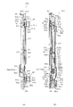
ここで、図7は、施錠装置600及びこれに関連する外枠11、内枠12及び前面枠14などの各部材を示す分解斜視図である。図8は、これらを組み付けた状態を示す斜視図であり、図9は、そこから前面枠14を開放した状態を示す斜視図であり、図10は、さらに内枠12を開放した状態を示す斜視図である。但し、図7〜図10では、便宜上、内枠12及び前面枠14に関しては、遊技盤30やガラスユニット137など各種部材を取外した状態の樹脂ベース37,38のみを図示している。   Here, FIG. 7 is an exploded perspective view showing the locking device 600 and each member such as the outer frame 11, the inner frame 12, and the front frame 14 related thereto. FIG. 8 is a perspective view showing a state where these are assembled, FIG. 9 is a perspective view showing a state where the front frame 14 is opened therefrom, and FIG. 10 shows a state where the inner frame 12 is further opened. It is a perspective view. However, in FIGS. 7 to 10, for the sake of convenience, only the resin bases 37 and 38 in a state where various members such as the game board 30 and the glass unit 137 are removed are illustrated for the inner frame 12 and the front frame 14.

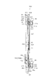
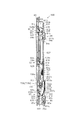
また、図11は施錠装置600を正面左側から見た斜視図であり、図12は施錠装置600を正面右側から見た斜視図であり、図13は施錠装置600を背面左側から見た斜視図であり、図14は施錠装置600を背面右側から見た斜視図である。また、図15は施錠装置600の正面図であり、図16は左側面図であり、図17は右側面図であり、図18は背面図である。なお、説明の便宜上、図11〜図18では、施錠装置600に関連する外枠11の内鉤部84,85や、前面枠14の前鉤部91,92,93等も併せて、組付けた状態で図示している。   11 is a perspective view of the locking device 600 viewed from the front left side, FIG. 12 is a perspective view of the locking device 600 viewed from the front right side, and FIG. 13 is a perspective view of the locking device 600 viewed from the back left side. FIG. 14 is a perspective view of the locking device 600 viewed from the rear right side. 15 is a front view of the locking device 600, FIG. 16 is a left side view, FIG. 17 is a right side view, and FIG. 18 is a rear view. For convenience of explanation, in FIGS. 11 to 18, the inner flange portions 84 and 85 of the outer frame 11 related to the locking device 600 and the front flange portions 91, 92 and 93 of the front frame 14 are also assembled. It is shown in the state.

また、図19は、施錠装置600等の分解図である。但し、図19では、便宜上、見やすいように各構成部品の向きを部品毎に変化させるとともに、内鉤部84,85や前鉤部91,92,93等も併せて図示している。   FIG. 19 is an exploded view of the locking device 600 and the like. However, in FIG. 19, for the sake of convenience, the orientation of each component is changed for each component so that it can be easily seen, and the inner flange portions 84 and 85, the front flange portions 91, 92, and 93 are also illustrated.

施錠装置600は、内枠12の右側辺部の前面側に取付けられている。施錠装置600の外郭を構成する基枠部材としての縦長の基枠601は、内枠12に固定される取付部としての取付板602と、当該取付板602の内枠12内方側(窓孔39側)の端縁から後方に突出した支持部としての支持板603と、当該支持板603の後端縁部から内枠12外方側に突出したフランジ部604(後述する膨出部603aの形成区間を除く)とを備えている。取付板602に比べややフランジ部604の突出長が短いものの、基枠601は、取付板602、支持板603及びフランジ部604が一体となって横断面略コ字状をなしている。なお、基枠601や後述する第1摺動杆607等の各摺動杆など、施錠装置600を構成する各部材は、金属平板をプレス成形等することにより形成されている。   The locking device 600 is attached to the front side of the right side portion of the inner frame 12. A vertically long base frame 601 as a base frame member constituting the outer shell of the locking device 600 includes a mounting plate 602 as a mounting portion fixed to the inner frame 12, and an inner frame 12 inner side (window hole) of the mounting plate 602. The support plate 603 as a support portion projecting rearward from the edge on the 39th side), and a flange portion 604 projecting outward from the inner frame 12 from the rear end edge portion of the support plate 603 (of a bulging portion 603a described later) Except for the formation section). Although the protruding length of the flange portion 604 is slightly shorter than that of the mounting plate 602, the base frame 601 has a substantially U-shaped cross section in which the mounting plate 602, the support plate 603, and the flange portion 604 are integrated. In addition, each member which comprises the locking device 600, such as each sliding rod, such as the base frame 601 and the 1st sliding rod 607 mentioned later, is formed by press-molding a metal flat plate.

これに対し、内枠12の前面側には、図10等に示すように、施錠装置600を取付けるための収容部(溝部)としての取付溝部901が右側辺部に沿って形成されている。これにより、前面枠14の閉状態においては、当該前面枠14と内枠12との間に施錠装置600を収容するための収容空間が形成されることとなる。   On the other hand, on the front side of the inner frame 12, as shown in FIG. 10 and the like, an attachment groove portion 901 as a housing portion (groove portion) for attaching the locking device 600 is formed along the right side portion. Thereby, in the closed state of the front frame 14, an accommodation space for accommodating the locking device 600 is formed between the front frame 14 and the inner frame 12.

取付溝部901には、複数のボス(図示略)が突設されている。これに対応して、取付板602には、複数のネジ孔602dが穿設されている。これにより、施錠装置600は、取付溝部901に嵌め込まれた状態で、内枠12の前面側からネジ(図示略)によりボスに固定される。   A plurality of bosses (not shown) protrude from the mounting groove 901. Correspondingly, a plurality of screw holes 602d are formed in the mounting plate 602. Thereby, the locking device 600 is fixed to the boss by the screw (not shown) from the front side of the inner frame 12 in a state where the locking device 600 is fitted in the mounting groove 901.

また、図3、図9等に示すように、施錠装置600が取付溝部901に嵌め込まれた状態では、取付板602の右端縁部及び支持板603がそれぞれ取付溝部901の側壁面に略当接状態となる。   Further, as shown in FIGS. 3 and 9, when the locking device 600 is fitted in the mounting groove 901, the right edge portion of the mounting plate 602 and the support plate 603 are substantially in contact with the side wall surface of the mounting groove 901. It becomes a state.

また、図4に示すように、取付溝部901の奥壁部901aには、外枠11の内鉤部84,85に対応して、内枠12の背面側へ貫通する挿通孔908,909が形成されている。これにより、内鉤部84,85は当該挿通孔908,909を介して、内枠12の前面側へ突出可能となる。また、挿通孔908,909の周囲にはリブ908a,909aが後方へ突出形成されている。取付溝部901の奥壁部901aが本実施形態における収容部の背壁部に相当する。   Further, as shown in FIG. 4, insertion holes 908 and 909 that penetrate to the back side of the inner frame 12 correspond to the inner flange portions 84 and 85 of the outer frame 11 in the rear wall portion 901 a of the mounting groove portion 901. Is formed. As a result, the inner flange portions 84 and 85 can project to the front side of the inner frame 12 through the insertion holes 908 and 909. Further, ribs 908a and 909a are formed to protrude rearward around the insertion holes 908 and 909. The back wall portion 901a of the mounting groove portion 901 corresponds to the back wall portion of the housing portion in the present embodiment.

施錠装置600の説明に戻り、取付板602では、シリンダ錠700の配置位置に対応する所定の上下区間が他部位より左右方向に幅広の幅広部602aとなっており、支持板603では、前記幅広部602aに対応する上下区間が内枠12内方側へ膨出した膨出部603aとなっている。これは、遊技領域や各種制御基板等の設置スペースをより広く確保するために、施錠装置600全体の横幅を極力狭くしつつ、シリンダ錠700の配設位置においては、その設置スペースを確保するためである。勿論、取付溝部901の形状も幅広部602a等に併せた形状となっている。   Returning to the description of the locking device 600, in the mounting plate 602, a predetermined upper and lower section corresponding to the arrangement position of the cylinder lock 700 is a wide portion 602 a that is wider in the left-right direction than other portions. An upper and lower section corresponding to the portion 602a is a bulging portion 603a bulging inwardly of the inner frame 12. This is to secure the installation space at the position where the cylinder lock 700 is disposed while reducing the overall width of the locking device 600 as much as possible in order to secure a wider installation space for the game area and various control boards. It is. Of course, the shape of the mounting groove 901 is also combined with the wide portion 602a and the like.

ここで、まず内枠12の施錠機構を主として構成する第1摺動杆607について説明する。第1摺動杆607は、長尺状をなし、支持板603の内枠12外方側に沿って上下方向に摺動可能なように配設されている。第1摺動杆607が本実施形態における第1摺動部材を構成する。   Here, first, the first sliding rod 607 that mainly constitutes the locking mechanism of the inner frame 12 will be described. The first sliding rod 607 has a long shape and is arranged to be slidable in the vertical direction along the outer side of the inner frame 12 of the support plate 603. The first sliding rod 607 constitutes the first sliding member in the present embodiment.

支持板603の膨出部603aに対応する第1摺動杆607の上下方向所定区間には、内枠12内方側へ膨出した膨出部607aが形成されている。但し、第1摺動杆607の膨出部607aの形成区間は、支持板603の膨出部603aの形成区間よりも短く設定されており、第1摺動杆607の摺動の妨げとならないようになっている。   A bulging portion 607 a bulging inward of the inner frame 12 is formed in a predetermined vertical direction of the first sliding rod 607 corresponding to the bulging portion 603 a of the support plate 603. However, the forming section of the bulging portion 607a of the first sliding rod 607 is set shorter than the forming section of the bulging portion 603a of the support plate 603, and does not hinder the sliding of the first sliding rod 607. It is like that.

第1摺動杆607の後端縁部には、内枠12施錠用の上下一対の内鉤受部609,610が形成されている。内鉤受部609,610は、第1摺動杆607の後端縁部から内枠12外方側へ突出形成された略平板状をなす。内鉤受部609,610が本実施形態における第1鉤受部を構成する。   A pair of upper and lower inner flange receiving portions 609 and 610 for locking the inner frame 12 are formed at the rear end edge of the first sliding rod 607. The inner flange receiving portions 609 and 610 have a substantially flat plate shape protruding from the rear end edge portion of the first sliding rod 607 toward the outer side of the inner frame 12. The inner collar receiving portions 609 and 610 constitute the first collar receiving portion in the present embodiment.

内鉤受部609,610に対応して、基枠601のフランジ部604には、その先端部よりさらに内枠12外方側へ延出した延出部613,614が形成されている。延出部613,614は、内鉤受部609,610と重畳するように形成されており、内鉤受部609,610と常時略当接状態で内鉤受部609,610を支持している。   Corresponding to the inner flange receiving portions 609 and 610, the flange portion 604 of the base frame 601 is formed with extending portions 613 and 614 extending further outward from the front end portion of the inner frame 12. The extending portions 613 and 614 are formed so as to overlap with the inner flange receiving portions 609 and 610, and support the inner flange receiving portions 609 and 610 in a state of being substantially in contact with the inner flange receiving portions 609 and 610 at all times. Yes.

延出部613,614には、内鉤受部609,610に対応して、略矩形状の挿入孔613a,614aが形成されている。そして、通常時には、内鉤受部609,610により、挿入孔613a,614aの上部が塞がされた状態となる。   In the extending portions 613 and 614, substantially rectangular insertion holes 613a and 614a are formed corresponding to the inner flange receiving portions 609 and 610, respectively. In normal times, the upper portions of the insertion holes 613a and 614a are closed by the inner flange receiving portions 609 and 610.

次に前面枠14の施錠機構を主として構成する第2摺動杆627について説明する。第2摺動杆627は、長尺状をなし、上下方向に摺動可能なように第1摺動杆607の内枠12外方側に重畳して配設されている。第2摺動杆627が本実施形態における第2摺動部材を構成する。   Next, the 2nd sliding rod 627 which mainly comprises the locking mechanism of the front frame 14 is demonstrated. The second sliding rod 627 has a long shape and is disposed so as to overlap the outer side of the inner frame 12 of the first sliding rod 607 so as to be slidable in the vertical direction. The second sliding rod 627 constitutes the second sliding member in the present embodiment.

第1摺動杆607の膨出部607aに対応する第2摺動杆627の上下方向所定区間には、内枠12内方側へ膨出した膨出部627aが形成されている。但し、第2摺動杆627の膨出部627aの形成区間は、第1摺動杆607の膨出部607aの形成区間よりも短く設定されており、第2摺動杆627の摺動の妨げとならないようになっている。   A bulging portion 627 a bulging inwardly of the inner frame 12 is formed in a predetermined vertical direction of the second sliding rod 627 corresponding to the bulging portion 607 a of the first sliding rod 607. However, the forming section of the bulging portion 627a of the second sliding rod 627 is set shorter than the forming section of the bulging portion 607a of the first sliding rod 607. It does not become an obstacle.

第2摺動杆627の前端縁部には、上部、中部及び下部の3箇所に、前面枠14施錠用の前鉤受部628,629,630が形成されている。前鉤受部628,629,630が本実施形態における第2鉤受部を構成する。   On the front edge portion of the second sliding rod 627, front rod receiving portions 628, 629, and 630 for locking the front frame 14 are formed at three locations, an upper portion, a middle portion, and a lower portion. The front saddle receiving portions 628, 629, and 630 constitute a second saddle receiving portion in the present embodiment.

前鉤受部628,629,630は、第2摺動杆627の前端縁部から内枠12外方側へ突出形成された略平板状をなす。   The front rod receiving portions 628, 629, and 630 have a substantially flat plate shape protruding from the front edge portion of the second sliding rod 627 toward the outer side of the inner frame 12.

前鉤受部628,629,630には、それぞれ略矩形状の係合孔628a,629a,630aが形成されている。また、取付板602には、前鉤受部628,629,630(係合孔628a,629a,630a)に対応して、上下方向3箇所に矩形状の挿通孔631,632,633が形成されている。そして、通常時には、係合孔628a,629a,630aが取付板602の挿通孔631,632,633の上部に重なるように位置するとともに、前鉤受部628,629,630により挿通孔631,632,633の下部が塞がされた状態となる。   The front hook receiving portions 628, 629, 630 are formed with substantially rectangular engaging holes 628a, 629a, 630a, respectively. The mounting plate 602 is formed with rectangular insertion holes 631, 632, 633 at three positions in the vertical direction corresponding to the front collar receiving portions 628, 629, 630 (engagement holes 628a, 629a, 630a). ing. In normal times, the engagement holes 628 a, 629 a, and 630 a are positioned so as to overlap the upper portions of the insertion holes 631, 632, and 633 of the mounting plate 602, and the insertion holes 631 and 632 are formed by the front collar receiving portions 628, 629, and 630. , 633 are closed.

前鉤受部628,629,630のうち上側の前鉤受部628は、上側の内鉤受部609のやや上方位置に設けられている。一方、下側の前鉤受部630は、下側の内鉤受部610のやや上方位置に設けられている。   Of the front collar receiving sections 628, 629, and 630, the upper front collar receiving section 628 is provided at a position slightly above the upper inner collar receiving section 609. On the other hand, the lower front collar receiving portion 630 is provided at a position slightly above the lower inner collar receiving portion 610.

さて、第1摺動杆607には、上下方向に3つのガイド孔615,616,617が形成されている。このうち、上下のガイド孔615,617は、内鉤受部609,610の高さ位置に対応して設けられている。ガイド孔615,616,617は、上下方向に長い長円状をなす。   Now, in the first sliding rod 607, three guide holes 615, 616, 617 are formed in the vertical direction. Among these, the upper and lower guide holes 615 and 617 are provided corresponding to the height positions of the inner flange receiving portions 609 and 610. The guide holes 615, 616, and 617 have an oval shape that is long in the vertical direction.

これに対応して、第2摺動杆627には、上下方向に3つのガイド孔635,636,637が形成されている。ガイド孔635,636,637は、前鉤受部628,629,630の高さ位置に対応して設けられている。ガイド孔635,636,637は、上下方向に長い長円状をなす。   Correspondingly, the second sliding rod 627 is formed with three guide holes 635, 636, 637 in the vertical direction. The guide holes 635, 636, 637 are provided corresponding to the height positions of the front collar receiving portions 628, 629, 630. The guide holes 635, 636, and 637 have an oval shape that is long in the vertical direction.

そして、第1摺動杆607のガイド孔615,616,617と第2摺動杆627のガイド孔635,636,637とをそれぞれ連通させた状態で、これらに対し内枠12外方側からガイドピン618,619,620が挿通され、当該ガイドピン618,619,620が支持板603に固定されている。   The guide holes 615, 616, and 617 of the first sliding rod 607 and the guide holes 635, 636, and 637 of the second sliding rod 627 are communicated with each other from the outer side of the inner frame 12. Guide pins 618, 619, 620 are inserted, and the guide pins 618, 619, 620 are fixed to the support plate 603.

上記構成により、第1摺動杆607及び第2摺動杆627は、取付板602とフランジ部604により前後方向への動きを規制され、かつ、ガイドピン618,619,620により左右方向への動きを規制されつつ、上下方向へ摺動可能となる。   With the above configuration, the first sliding rod 607 and the second sliding rod 627 are restricted from moving in the front-rear direction by the mounting plate 602 and the flange portion 604, and are moved in the left-right direction by the guide pins 618, 619, 620. It is possible to slide up and down while the movement is restricted.

さて、通常時、第1摺動杆607及び第2摺動杆627は、付勢手段としてのコイルばねC1により、それぞれ下方又は上方へ付勢されている。より詳しくは、第1摺動杆607には、フック部621が設けられている。また、第2摺動杆627にはフック部641が設けられている。さらに、第2摺動杆627には、第1摺動杆607のフック部621に対応して、フック部641の上方位置において上下方向に長い略矩形状の挿通孔642が形成されている。   Now, at the normal time, the first sliding rod 607 and the second sliding rod 627 are respectively urged downward or upward by a coil spring C1 as an urging means. More specifically, the first sliding rod 607 is provided with a hook portion 621. The second sliding rod 627 is provided with a hook portion 641. Further, the second sliding rod 627 is formed with a substantially rectangular insertion hole 642 that is long in the vertical direction at a position above the hook portion 641 corresponding to the hook portion 621 of the first sliding rod 607.

そして、第1摺動杆607のフック部621にコイルばねC1の一端が掛けられるとともに、挿通孔642を介して、他端が第2摺動杆627のフック部641に掛けられている。   One end of the coil spring C1 is hooked on the hook portion 621 of the first sliding rod 607, and the other end is hooked on the hook portion 641 of the second sliding rod 627 through the insertion hole 642.

上記コイルばねC1の引張力によって、通常時には、第1摺動杆607は、ガイド孔615,616,617の上縁部がガイドピン618,619,620に付勢され、下方への動作が抑えられた状態で保持されている。一方、第2摺動杆627は、ガイド孔635,636,637の下縁部がガイドピン618,619,620に付勢され、上方への動作が抑えられた状態で保持されている。そして、後述するシリンダ錠700が操作された場合には、コイルばねC1の引張力に抗して、第1摺動杆607は上方へ、又は第2摺動杆627は下方へ摺動変位する。   Due to the tensile force of the coil spring C1, the upper edge of the guide hole 615, 616, 617 is normally urged by the guide pins 618, 619, 620 to suppress the downward movement of the first sliding rod 607. Is held in a locked state. On the other hand, the second sliding rod 627 is held in a state where the lower edges of the guide holes 635, 636, 637 are urged by the guide pins 618, 619, 620, and the upward movement is suppressed. When a cylinder lock 700 described later is operated, the first sliding rod 607 is displaced upward or the second sliding rod 627 is displaced downward against the tensile force of the coil spring C1. .

なお、第1摺動杆607の摺動範囲のうち、ガイド孔615,616,617の上縁部がガイドピン618,619,620に当接する位置が、内鉤部84,85が内鉤受部609,610に係合される位置となる。つまり、この位置が第1摺動杆607(内鉤受部609,610)の施錠位置(基準位置)に相当する。従って、第1摺動杆607がこの位置にある状態が、内枠12の施錠機構の施錠状態に相当する。   In the sliding range of the first sliding rod 607, the positions where the upper edge portions of the guide holes 615, 616, 617 abut on the guide pins 618, 619, 620 are the inner flange portions 84, 85. It becomes a position engaged with the parts 609 and 610. That is, this position corresponds to the locking position (reference position) of the first sliding rod 607 (inner rod receiving portions 609, 610). Therefore, the state in which the first sliding rod 607 is in this position corresponds to the locking state of the locking mechanism of the inner frame 12.

これに対し、ガイド孔615,616,617の下縁部がガイドピン618,619,620に当接する位置が、内鉤部84,85が内鉤受部609,610から離脱(係合解除)した位置となる。つまり、この位置が第1摺動杆607の解錠位置に相当する。従って、第1摺動杆607がこの位置にある状態が、内枠12の施錠機構の解錠状態に相当する。   On the other hand, the positions where the lower edge portions of the guide holes 615, 616, and 617 contact the guide pins 618, 619, and 620 are separated from the inner flange receiving portions 609 and 610 (disengagement). It becomes the position. That is, this position corresponds to the unlocking position of the first sliding rod 607. Therefore, the state where the first sliding bar 607 is in this position corresponds to the unlocked state of the locking mechanism of the inner frame 12.

一方、第2摺動杆627の摺動範囲のうち、ガイド孔635,636,637の下縁部がガイドピン618,619,620に当接する位置が、前鉤部91,92,93が前鉤受部628,629,630に係合される位置となる。つまり、この位置が第2摺動杆627(前鉤受部628,629,630)の施錠位置(基準位置)に相当する。従って、第2摺動杆627がこの位置にある状態が、前面枠14の施錠機構の施錠状態に相当する。   On the other hand, in the sliding range of the second sliding rod 627, the position where the lower edge portion of the guide hole 635, 636, 637 abuts on the guide pins 618, 619, 620 is the front collar portion 91, 92, 93. It becomes a position engaged with the hook receiving parts 628, 629, and 630. That is, this position corresponds to the locking position (reference position) of the second sliding rod 627 (front rod receiving portions 628, 629, 630). Therefore, the state where the second sliding rod 627 is in this position corresponds to the locking state of the locking mechanism of the front frame 14.

これに対し、ガイド孔635,636,637の上縁部がガイドピン618,619,620に当接する位置が、前鉤部91,92,93が前鉤受部628,629,630から離脱(係合解除)した位置となる。つまり、この位置が第2摺動杆627の解錠位置に相当する。従って、第2摺動杆627がこの位置にある状態が、前面枠14の施錠機構の解錠状態に相当する。   On the other hand, the positions where the upper edge portions of the guide holes 635, 636, 637 abut on the guide pins 618, 619, 620 are separated from the front collar receiving portions 628, 629, 630 ( The position is disengaged. That is, this position corresponds to the unlocking position of the second sliding rod 627. Therefore, the state where the second sliding rod 627 is in this position corresponds to the unlocked state of the locking mechanism of the front frame 14.

さて、取付板602の幅広部602aには、錠部材としてのシリンダ錠700が取付けられている。   A cylinder lock 700 serving as a lock member is attached to the wide portion 602a of the attachment plate 602.

シリンダ錠700は、取付板602の背面に固定される固定部700aと、当該固定部700aから前方に向けて取付板602を貫通して延び、その内部に錠軸(図示略)を有しかつその前面側に鍵穴702を有する錠本体700bと、固定部700aの背面側にて前記錠軸に連結され、鍵穴702に挿入された鍵の回動動作を第1摺動杆607又は第2摺動杆627に伝達する伝達部材としてのカム板720とを備えている。   The cylinder lock 700 has a fixing portion 700a fixed to the back surface of the mounting plate 602, and extends through the mounting plate 602 from the fixing portion 700a forward, and has a lock shaft (not shown) therein. A lock main body 700b having a key hole 702 on the front surface side, and a rotation operation of a key connected to the lock shaft on the back surface side of the fixing portion 700a and inserted into the key hole 702 is performed by the first slide rod 607 or the second slide. And a cam plate 720 serving as a transmission member that transmits the moving rod 627.

また、固定部700aの背面側には、後方に突出し、鍵穴702の形状(キーコード)を変更する際に押圧操作される操作部としてのリセットピン703が設けられている。これに対応して、内枠12の背面側(取付溝部901の奥壁部901a)には、図4に示すように、操作用孔部としてのピン孔901bが形成されている。   Further, a reset pin 703 is provided on the back side of the fixed portion 700a as an operation portion that protrudes rearward and is pressed when the shape (key code) of the keyhole 702 is changed. Correspondingly, a pin hole 901b as an operation hole is formed on the back side of the inner frame 12 (the inner wall 901a of the mounting groove 901) as shown in FIG.

ここで、キーコードの変更手順の一例について説明する。まず内枠12を開放させた状態で、ピン孔901bを介して所定の治具を挿入し、リセットピン703を押圧する。この状態で鍵穴702に現状の鍵を挿入して回動操作した後、該鍵を引き抜く。そして、リセットピン703を押圧したまま、新たに設定したい鍵を鍵穴702に挿入し、前記現状の鍵とは逆向きに回動操作した後、リセットピン703の押圧状態を解除してから鍵を引き抜く。以上のような操作を行うことで、新たに設定したい鍵に合ったキーコードとすることができる。これにより、遊技場単位で鍵を統一できるとともに、不正防止のため、定期的に鍵を変更することができる。   Here, an example of the key code changing procedure will be described. First, with the inner frame 12 open, a predetermined jig is inserted through the pin hole 901b and the reset pin 703 is pressed. In this state, the current key is inserted into the keyhole 702 and rotated, and then the key is pulled out. Then, with the reset pin 703 pressed, a new key to be set is inserted into the key hole 702, and the key is released after the pressing state of the reset pin 703 is released after rotating the reverse direction of the current key. Pull out. By performing the operation as described above, a key code suitable for a new key to be set can be obtained. As a result, it is possible to unify the keys for each game hall and to periodically change the keys to prevent fraud.

カム板720は、上係合爪720a及び下係合爪720bを備えている。これらの係合爪720a,720bは、カム板720の回動方向に所定間隔を置いて形成されている。   The cam plate 720 includes an upper engagement claw 720a and a lower engagement claw 720b. These engaging claws 720a and 720b are formed at predetermined intervals in the rotational direction of the cam plate 720.

カム板720に対応して、第1摺動杆607の膨出部607aには、係合爪720a,720bが出入可能な上下一対の上係合孔725及び下係合孔726が形成されている。同様に、第2摺動杆627の膨出部627aには、係合爪720a,720bが出入可能な上下一対の上係合孔727及び下係合孔728が形成されている。また、支持板603には、係合爪720a,720bの動作を妨げないように透孔730が形成されている。   Corresponding to the cam plate 720, a bulging portion 607a of the first sliding rod 607 is formed with a pair of upper and lower upper engaging holes 725 and lower engaging holes 726 into which the engaging claws 720a and 720b can enter and exit. Yes. Similarly, a pair of upper and lower upper engagement holes 727 and 728 into which the engagement claws 720a and 720b can enter and exit are formed in the bulging portion 627a of the second sliding rod 627. Further, a through hole 730 is formed in the support plate 603 so as not to hinder the operation of the engaging claws 720a and 720b.

各係合孔725〜728は、上下方向に長い略矩形の長孔状をなす。そして、第1摺動杆607及び第2摺動杆627の通常時の重畳状態にあっては、少なくとも上係合孔725,727同士、及び、下係合孔726,728同士が部分的に重なり合い、そこに係合爪720a,720bがそれぞれ挿し込まれた状態となる。   Each of the engagement holes 725 to 728 has a substantially rectangular long hole shape that is long in the vertical direction. In the normal overlapping state of the first sliding rod 607 and the second sliding rod 627, at least the upper engagement holes 725 and 727 and the lower engagement holes 726 and 728 are partially partially formed. It overlaps and it will be in the state by which the engaging claws 720a and 720b were each inserted.

より詳しくは、図11,13に示すように、シリンダ錠700の鍵穴702に鍵が挿し込まれていない状態で、カム板720が基準位置にある場合には、上係合爪720aの先端が、第1摺動杆607及び第2摺動杆627の上係合孔725,727に挿通状態となるとともに、下係合爪720bの先端が、第1摺動杆607及び第2摺動杆627の下係合孔726,728に挿通状態となる。   More specifically, as shown in FIGS. 11 and 13, when the cam plate 720 is at the reference position in a state where the key is not inserted into the key hole 702 of the cylinder lock 700, the tip of the upper engaging claw 720a is The first sliding rod 607 and the second sliding rod 627 are inserted into the upper engagement holes 725 and 727, and the lower engagement claw 720 b has a distal end connected to the first sliding rod 607 and the second sliding rod 607. 627 enters the lower engagement holes 726 and 728.

次に、施錠装置600の作用について詳しく説明する。まず内枠12の施錠及び解錠について詳しく説明する。内枠12の施錠状態においては、第1摺動杆607が基準位置をとることにより、内鉤受部609,610に、外枠11の内鉤部84,85が係合され、内枠12の開放が規制されている。   Next, the operation of the locking device 600 will be described in detail. First, locking and unlocking of the inner frame 12 will be described in detail. In the locked state of the inner frame 12, the first sliding rod 607 takes the reference position, whereby the inner flange portions 84 and 85 of the outer frame 11 are engaged with the inner rod receiving portions 609 and 610, and the inner frame 12. The opening of is regulated.

そして、内枠12を解錠する際には、シリンダ錠700の鍵穴702に鍵を挿入し、パチンコ機10の正面側(図1参照)から見て時計回り方向に回動させる。この操作が本実施形態における第1操作に相当する。これにより、カム板720が同方向に回動して、下係合爪720bが第1摺動杆607の下係合孔726の上縁部に接触する。   When the inner frame 12 is unlocked, a key is inserted into the key hole 702 of the cylinder lock 700 and rotated clockwise as viewed from the front side of the pachinko machine 10 (see FIG. 1). This operation corresponds to the first operation in the present embodiment. As a result, the cam plate 720 rotates in the same direction, and the lower engagement claw 720b contacts the upper edge portion of the lower engagement hole 726 of the first sliding rod 607.

その後、さらにカム板720を回動させていくに従って、図20(a),(b)及び図22(a),(b)に示すように、下係合爪720bがコイルばねC1の引張力に抗して第1摺動杆607を上方へ押し上げていく。同時に、上係合爪720aは第1摺動杆607及び第2摺動杆627に作用を及ぼすことなく、両上係合孔725,727から離脱する。この際、下係合爪720bが挿通された第2摺動杆627の下係合孔728の上部には、下係合爪720bが上方へ変位するスペースが確保されているため、第1摺動杆607を押し上げていく過程において、下係合爪720bが第2摺動杆627に当接せず、その動作が妨げられないようになっている。   Thereafter, as the cam plate 720 is further rotated, as shown in FIGS. 20 (a) and 20 (b) and FIGS. 22 (a) and 22 (b), the lower engaging claw 720b is pulled by the coil spring C1. The first sliding rod 607 is pushed upward against this. At the same time, the upper engaging claw 720a is detached from the upper engaging holes 725 and 727 without acting on the first sliding rod 607 and the second sliding rod 627. At this time, a space for the lower engagement claw 720b to be displaced upward is secured above the lower engagement hole 728 of the second sliding rod 627 through which the lower engagement claw 720b is inserted. In the process of pushing up the moving rod 607, the lower engaging claw 720b does not come into contact with the second sliding rod 627 so that the operation is not hindered.

第1摺動杆607が上方へ摺動すると、内鉤受部609,610と、内鉤部84,85との係合が解除され、内枠12の開放が許容される。また、内枠12が開放された時点で、鍵を操作する手の力を緩めると、コイルばねC1の引張力により、第1摺動杆607は下方へ引き下げられ、基準位置に復帰する。これに伴い、カム板720及び錠軸も基準位置に復帰する。   When the first sliding rod 607 slides upward, the engagement between the inner flange receiving portions 609 and 610 and the inner flange portions 84 and 85 is released, and the opening of the inner frame 12 is allowed. Further, when the force of the hand operating the key is loosened when the inner frame 12 is opened, the first sliding rod 607 is pulled downward by the tensile force of the coil spring C1, and returns to the reference position. Accordingly, the cam plate 720 and the lock shaft also return to the reference position.

一方、開状態にある内枠12を施錠する際には、鍵を用いずに、内枠12を閉じていき、外枠11の内鉤部84,85の頭部84d,85dの傾斜部位が内鉤受部609,610の下縁部にぶつかると、第1摺動杆607に上方向への外力が加わり、第1摺動杆607がコイルばねC1の引張力に抗して上方へ摺動する。そして、内鉤部84,85の頭部84d,85dが内鉤受部609,610の下縁部を乗り越えると、第1摺動杆607がコイルばねC1の引張力により元の位置に戻る。これにより、内鉤受部609,610に対し内鉤部84,85が係合され、内枠12が施錠された状態となる。   On the other hand, when locking the inner frame 12 in the open state, the inner frame 12 is closed without using a key, and the inclined portions of the head portions 84d and 85d of the inner collar portions 84 and 85 of the outer frame 11 are formed. When it hits the lower edge of the inner flange receiving portions 609 and 610, an upward external force is applied to the first sliding rod 607, and the first sliding rod 607 slides upward against the tensile force of the coil spring C1. Move. When the head portions 84d and 85d of the inner flange portions 84 and 85 get over the lower edge portions of the inner flange receiving portions 609 and 610, the first sliding rod 607 returns to the original position by the tensile force of the coil spring C1. As a result, the inner collar portions 84 and 85 are engaged with the inner collar receiving portions 609 and 610, and the inner frame 12 is locked.

次に前面枠14の施錠及び解錠について詳しく説明する。前面枠14の施錠状態においては、第2摺動杆627が基準位置をとることにより、前鉤受部628,629,630に、前面枠14の前鉤部91,92,93が係合され、前面枠14の開放が規制される。   Next, locking and unlocking of the front frame 14 will be described in detail. In the locked state of the front frame 14, the second sliding rod 627 takes the reference position so that the front flange portions 91, 92, and 93 of the front frame 14 are engaged with the front rod receiving portions 628, 629, and 630. The opening of the front frame 14 is restricted.

そして、前面枠14を解錠する際には、シリンダ錠700の鍵穴702に鍵を挿入し、パチンコ機10の正面側から見て反時計回り方向に回動させる。この操作が本実施形態における第2操作に相当する。これにより、カム板720が同方向に回動して、上係合爪720aが第2摺動杆627の上係合孔727の下縁部に接触する。   When unlocking the front frame 14, a key is inserted into the key hole 702 of the cylinder lock 700 and rotated counterclockwise as viewed from the front side of the pachinko machine 10. This operation corresponds to the second operation in the present embodiment. As a result, the cam plate 720 rotates in the same direction, and the upper engagement claw 720a contacts the lower edge portion of the upper engagement hole 727 of the second sliding rod 627.

その後、さらにカム板720を回動させていくに従って、図21(a),(b)及び図23(a),(b)に示すように、上係合爪720aがコイルばねC1の引張力に抗して第2摺動杆627を下方へ押し下げていく。同時に、下係合爪720bは第2摺動杆627及び第1摺動杆607に作用を及ぼすことなく、両下係合孔726,728から離脱する。この際、上係合爪720aが挿通された第1摺動杆607の上係合孔725の下部には、上係合爪720aが下方へ変位するスペースが確保されているため、第2摺動杆627を押し下げていく過程において、上係合爪720aが第1摺動杆607に当接せず、その動作が妨げられないようになっている。   Thereafter, as the cam plate 720 is further rotated, as shown in FIGS. 21 (a), (b) and FIGS. 23 (a), (b), the upper engaging claw 720a is pulled by the coil spring C1. The second sliding rod 627 is pushed downward against this. At the same time, the lower engaging claw 720b is detached from both the lower engaging holes 726 and 728 without acting on the second sliding rod 627 and the first sliding rod 607. At this time, a space for the upper engagement claw 720a to be displaced downward is secured below the upper engagement hole 725 of the first sliding rod 607 through which the upper engagement claw 720a is inserted. In the process of pushing down the moving rod 627, the upper engaging claw 720a does not contact the first sliding rod 607, and the operation is not hindered.

第2摺動杆627が下方へ摺動すると、すべての前鉤受部628,629,630と、前鉤部91,92,93との係合が解除され、前面枠14の開放が許容される。また、前面枠14が開放された時点で、鍵を操作する手の力を緩めると、コイルばねC1の引張力により、第2摺動杆627は上方へ引き上げられ、基準位置に復帰する。これに伴い、カム板720及び錠軸も基準位置に復帰する。   When the second sliding rod 627 slides downward, the engagement of all the front collar receiving portions 628, 629, 630 and the front collar portions 91, 92, 93 is released, and the opening of the front frame 14 is allowed. The Further, when the force of the hand operating the key is loosened when the front frame 14 is opened, the second sliding rod 627 is pulled upward by the tensile force of the coil spring C1, and returns to the reference position. Accordingly, the cam plate 720 and the lock shaft also return to the reference position.

一方、開状態にある前面枠14を施錠する際には、鍵を用いずに、前面枠14を閉じていき、前面枠14の前鉤部91,92,93の頭部91c,92c,93cの傾斜部位が前鉤受部628,629,630の係合孔628a,629a,630aの下縁部にぶつかると、第2摺動杆627に下方向への外力が加わり、第2摺動杆627がコイルばねC1の引張力に抗して下方へ摺動する。そして、前鉤部91,92,93の頭部91c,92c,93cが前鉤受部628,629,630の係合孔628a,629a,630aの下縁部を乗り越えると、第2摺動杆627がコイルばねC1の引張力により元の位置に戻る。これにより、前鉤受部628,629,630に対し前鉤部91,92,93が係合され、前面枠14が施錠された状態となる。   On the other hand, when locking the front frame 14 in the open state, the front frame 14 is closed without using a key, and the heads 91c, 92c, 93c of the front flange portions 91, 92, 93 of the front frame 14 are closed. When the slanted portion of the front end collides with the lower edge of the engagement holes 628a, 629a, 630a of the front rod receiving portions 628, 629, 630, an external force is applied to the second sliding rod 627 in the downward direction, and the second sliding rod 627 slides downward against the tensile force of the coil spring C1. When the head portions 91c, 92c, 93c of the front collar portions 91, 92, 93 get over the lower edges of the engagement holes 628a, 629a, 630a of the front collar receiving portions 628, 629, 630, the second sliding collar 627 returns to the original position by the tensile force of the coil spring C1. As a result, the front collar portions 91, 92, 93 are engaged with the front collar receiving portions 628, 629, 630, and the front frame 14 is locked.

以上詳述したように、本実施形態では、施錠装置600が、内枠12と前面枠14との間に形成される収容空間に配置されるとともに、内枠12と基枠601との間に形成される内部空間に、内枠12の施錠機構及び前面枠14の施錠機構が配置される構成となっている。加えて、内枠12の背面側や基枠601の前面側に鉤部等が突出しない構成となっている。このため、仮に内枠12や前面枠14を不正に解錠する不正行為を行おうとした場合でも、線材を引っ掛けることのできる鉤部等の突出した部位がなく、前記不正行為を行うことは極めて困難となる。結果として、線材等を用いた不正解錠に対する防御性能を高めることができる。   As described above in detail, in the present embodiment, the locking device 600 is disposed in the accommodation space formed between the inner frame 12 and the front frame 14, and between the inner frame 12 and the base frame 601. In the formed internal space, the locking mechanism of the inner frame 12 and the locking mechanism of the front frame 14 are arranged. In addition, the collar portion or the like does not protrude from the back side of the inner frame 12 or the front side of the base frame 601. For this reason, even if it is attempted to perform an illegal act of illegally unlocking the inner frame 12 or the front frame 14, there is no protruding part such as a hook that can hook the wire rod, and it is extremely It becomes difficult. As a result, the defense performance against unauthorized unlocking using a wire or the like can be enhanced.

本実施形態では、施錠装置600に対応する上下区間全域を内枠12の背面側から覆うように延出壁部83が形成されている。また、その前方に設けられた内鉤部84,85は、内枠12の挿通孔908,909に相対向するように設けられた基部84b,85bを備えるとともに、当該基部84b,85bの外枠11内方側の端縁部から後方へ延出した折り返し部84e,85eを備えている。さらに、内枠12の挿通孔908,909の周囲にはリブ908a,909aが後方へ突出形成されている。これにより、内枠12の背面側から挿通孔908,909を介して線材等を進入させ、当該線材等により内枠12の施錠機構を操作するといった不正行為を行うことがさらに困難となり、さらなる防御性能の向上を図ることができる。   In the present embodiment, the extending wall portion 83 is formed so as to cover the entire upper and lower sections corresponding to the locking device 600 from the back side of the inner frame 12. In addition, the inner collar portions 84 and 85 provided in front of the same include base portions 84b and 85b provided so as to face the insertion holes 908 and 909 of the inner frame 12, and the outer frames of the base portions 84b and 85b. 11 is provided with folded portions 84e and 85e extending rearward from the inner edge. Further, ribs 908 a and 909 a are formed to protrude rearward around the insertion holes 908 and 909 of the inner frame 12. As a result, it becomes more difficult to perform a fraudulent act such as causing a wire rod or the like to enter from the back side of the inner frame 12 through the insertion holes 908 and 909 and operating the locking mechanism of the inner frame 12 with the wire rod or the like. The performance can be improved.

加えて、上記のように防御性能を高めることにより、施錠装置600自身の構成を比較的簡素なものにすることができる。   In addition, by increasing the defense performance as described above, the configuration of the locking device 600 itself can be made relatively simple.

また、本実施形態では、内枠12の背面側(取付溝部901の奥壁部901a)に形成されたピン孔901bを介して、シリンダ錠700のリセットピン703を押圧操作して鍵穴702の形状(キーコード)を変更可能に構成されている。これにより、リセットピン703を操作するために、わざわざ施錠装置600を内枠12から取外すといった手間をかけずに済む。結果として、不正解錠に対する防御性能の向上を図りつつも、利便性の向上をも両立して図ることができる。   In the present embodiment, the shape of the keyhole 702 is determined by pressing the reset pin 703 of the cylinder lock 700 via the pin hole 901b formed on the back side of the inner frame 12 (the back wall 901a of the mounting groove 901). (Key code) can be changed. This eliminates the need to bother to remove the locking device 600 from the inner frame 12 in order to operate the reset pin 703. As a result, while improving the defense performance against unauthorized unlocking, the convenience can be improved at the same time.

また、外枠11には、施錠装置600(取付溝部901の奥壁部901a)を内枠12の背面側から覆うように、延出壁部83が形成されている。これにより、内鉤部84,85及び内鉤受部609,610に対するさらなる防御性能の向上を図るとともに、奥壁部901aにピン孔901bが常時開口した状態のままであっても、当該ピン孔901bを介して線材等を進入させ、施錠装置600に対して不正行為を行うことは困難となる。   Further, an extension wall portion 83 is formed on the outer frame 11 so as to cover the locking device 600 (the back wall portion 901a of the mounting groove portion 901) from the back side of the inner frame 12. Thereby, while further improving the defense performance with respect to the inner flange portions 84 and 85 and the inner flange receiving portions 609 and 610, even if the pin hole 901b is always open in the back wall portion 901a, the pin hole It is difficult to enter a wire rod or the like via 901b and perform an illegal act on the locking device 600.

なお、上述した実施形態の記載内容に限定されず、例えば次のように実施してもよい。   In addition, it is not limited to the description content of embodiment mentioned above, For example, you may implement as follows.

(a)施錠装置600の構成は上記実施形態に限定されるものではない。例えば、上記実施形態では、内鉤受部609,610等の各鉤受部が第1摺動杆607等に一体形成されているが、これに限らず、例えば、内鉤受部609,610及び前鉤受部628,629,630に相当する部材をそれぞれ個別に基枠601に対し相対変位可能に組付けるとともに、これらを1つの摺動杆によって動かす構成としてもよい。   (A) The configuration of the locking device 600 is not limited to the above embodiment. For example, in the above-described embodiment, the flange receiving portions such as the inner flange receiving portions 609 and 610 are integrally formed with the first sliding rod 607 and the like. However, the present invention is not limited to this, for example, the inner flange receiving portions 609 and 610. The members corresponding to the front saddle receiving portions 628, 629, and 630 may be individually assembled so as to be relatively displaceable with respect to the base frame 601, and may be moved by one sliding rod.

(b)内鉤受部609,610や前鉤受部628,629,630の構成は上記実施形態に限定されるものではない。例えば、上記実施形態では、内鉤受部609,610等が上下方向に摺動変位する構成となっているが、これに限らず、例えば、内鉤受部609,610等に相当する部材が施錠位置と解錠位置とに回動変位する構成を採用してもよい。   (B) The configurations of the inner collar receiving portions 609, 610 and the front collar receiving portions 628, 629, 630 are not limited to the above embodiment. For example, in the above-described embodiment, the inner collar receiving portions 609, 610 and the like are configured to slide and move in the vertical direction. However, the present invention is not limited to this, and for example, members corresponding to the inner collar receiving portions 609, 610, and the like are provided. You may employ | adopt the structure which rotationally displaces to a locking position and an unlocking position.

また、内鉤受部609,610等の各鉤受部及びこれに対応する内鉤部84,85等の各鉤部の数は、上記実施形態の数に限定されるものではなく、例えば1つであってもよいし、内枠12の施錠機構に対応して3つ以上備えた構成としてもよい。   Moreover, the number of each collar part such as the inner collar parts 609 and 610 and the corresponding collar parts such as the inner collar parts 84 and 85 is not limited to the number of the above-described embodiments. Alternatively, three or more may be provided corresponding to the locking mechanism of the inner frame 12.

(c)シリンダ錠700の構成は上記実施形態に限定されるものではない。例えば、上記実施形態では、固定部700aの背面側にキーコードを変更するためのリセットピン703が設けられているが、リセットピン703が固定部700aの前面側に設けられ、内枠12の前面側からキーコードの変更操作を行うことができる構成としてもよい。また、固定部700aの背面側にリセットピン703が設けられているが、これを内枠12の前面側から操作可能とする機構を備えた構成としてもよい。これらの場合、内枠12の背面側のピン孔901bは省略することができる。また、このような構成とすれば、内枠12を外枠11から開放した不安定な状態でキーコードの変更操作を行う必要がなく、内枠12を外枠11に閉鎖し安定した状態のまま作業を行うことができるため、作業性の向上を図ることができる。   (C) The configuration of the cylinder lock 700 is not limited to the above embodiment. For example, in the above embodiment, the reset pin 703 for changing the key code is provided on the back side of the fixed portion 700a. However, the reset pin 703 is provided on the front side of the fixed portion 700a and The key code may be changed from the side. Further, although the reset pin 703 is provided on the back side of the fixed portion 700a, it may be configured to have a mechanism that can be operated from the front side of the inner frame 12. In these cases, the pin hole 901b on the back side of the inner frame 12 can be omitted. Also, with such a configuration, there is no need to perform a key code changing operation in an unstable state in which the inner frame 12 is released from the outer frame 11, and the inner frame 12 is closed to the outer frame 11 and is in a stable state. Since work can be performed as it is, workability can be improved.

また、上記実施形態では、取付溝部901の奥壁部901aに形成されたピン孔901bが常時開放した状態となっているが、これに限らず、ピン孔901b等の操作用孔部が通常時は閉じられ、使用時には開けられる構成を採用し防御性能を高めてもよい。   Moreover, in the said embodiment, although the pin hole 901b formed in the back wall part 901a of the attachment groove part 901 is a state always open | released, not only this but operation hole parts, such as the pin hole 901b, are normal. May be closed, and may be opened when in use to improve defense performance.

例えば、図24に示すように、ピン孔901bを塞ぐ蓋部920を取付溝部901の奥壁部901aに対し取外し不能に組付けた構成を採用してもよい。   For example, as shown in FIG. 24, a configuration may be employed in which a lid portion 920 that closes the pin hole 901b is assembled to the rear wall portion 901a of the mounting groove portion 901 so as not to be removable.

より詳しくは、蓋部920の前面側には、上下2箇所ずつに係止爪920aが突出形成されている。これに対応して、奥壁部901aには係止孔901cが4つ形成されている。そして、当該係止爪920aを奥壁部901a前面側に係止することにより、当該蓋部920が組付けられる。蓋部920が奥壁部901aに組付けられた状態では、係止爪920aが奥壁部901a前面側に位置するため、内枠12の背面側から係止解除操作を行うことができなくなる。また、内枠12の前面側では施錠装置600の基枠601により取付溝部901が塞がれた状態となっているため、施錠装置600を取外す等しない限り、内枠12の前面側からも係止解除操作することはできない。つまり、蓋部920は、破壊等しない限り、取外せない状態となる。   More specifically, locking claws 920a are formed on the front side of the lid portion 920 so as to protrude from the upper and lower portions. Correspondingly, four locking holes 901c are formed in the back wall portion 901a. And the said cover part 920 is assembled | attached by latching the said latching claw 920a to the back wall part 901a front side. In a state where the lid portion 920 is assembled to the back wall portion 901a, the latching claw 920a is located on the front surface side of the back wall portion 901a, so that the unlocking operation cannot be performed from the back side of the inner frame 12. Further, since the mounting groove 901 is closed by the base frame 601 of the locking device 600 on the front side of the inner frame 12, the front side of the inner frame 12 is also engaged unless the locking device 600 is removed. The stop / release operation cannot be performed. That is, the lid 920 is in a state that cannot be removed unless it is destroyed.

一方、キーコードを変更しなくてはならない状況となった場合には、マイナスドライバー等の工具を蓋部920と奥壁部901aとの間に挿し込み、蓋部920(係止爪920a)を破壊する等して取外してピン孔901bを開放させることにより、当該ピン孔901bを介してシリンダ錠700のリセットピン703を操作することができる。なお、蓋部920を破壊する等して使用した場合でも、当該使用済みの蓋部920のみを、未使用の新たな蓋部920に取り替えるだけで元の状態に戻すことができる。   On the other hand, when it becomes necessary to change the key code, a tool such as a flathead screwdriver is inserted between the lid 920 and the back wall 901a, and the lid 920 (locking claw 920a) is inserted. The reset pin 703 of the cylinder lock 700 can be operated through the pin hole 901b by removing the pin hole 901b by breaking it or the like. Even when the lid portion 920 is used by being destroyed or the like, only the used lid portion 920 can be returned to the original state only by replacing it with a new unused lid portion 920.

また、図25に示すように、シリンダ錠700のリセットピン703の位置に対応して、取付溝部901の奥壁部901aの一部に切離し可能な蓋部903を備えることにより、当該奥壁部901aにリセットピン703を操作するための操作用孔部が形成される構成としてもよい。   Further, as shown in FIG. 25, corresponding to the position of the reset pin 703 of the cylinder lock 700, the back wall portion is provided with a detachable lid portion 903 on a part of the back wall portion 901 a of the mounting groove portion 901. An operation hole for operating the reset pin 703 may be formed in 901a.

より詳しくは、奥壁部901aには、略矩形状の範囲を囲むようにミシン目状に複数のスリット901dが間欠的に設けられている。これにより、スリット901dにより囲まれた部位が蓋部903として画定されている。そして、キーコードを変更する場合には、カッター等の工具によりスリット901dに沿って蓋部903の周囲を切断することにより当該蓋部903を奥壁部901aの本体部から切離す。こうすることで、奥壁部901aには操作用孔部が形成され、当該操作用孔部を介して、リセットピン703を操作することができるようになる。   More specifically, a plurality of slits 901d are intermittently provided in the back wall portion 901a in a perforated manner so as to surround a substantially rectangular range. As a result, the portion surrounded by the slit 901d is defined as the lid portion 903. And when changing a key code, the said cover part 903 is cut away from the main-body part of the back wall part 901a by cut | disconnecting the circumference | surroundings of the cover part 903 along slit 901d with tools, such as a cutter. By doing so, an operation hole is formed in the back wall 901a, and the reset pin 703 can be operated through the operation hole.

スリット901dに代えて、蓋部903の全周囲に薄肉部を設けることにより、奥壁部901aから切断可能となる構成としてもよい。このようにすれば、通常時には、線材等が進入する隙間が形成されないため、防御性能を高めることができる。   Instead of the slit 901d, a thin wall portion may be provided around the entire lid portion 903 so that the rear wall portion 901a can be cut. In this way, since a gap through which a wire rod or the like enters is not formed at normal times, the defense performance can be improved.

蓋部903が切離されると、奥壁部901aにはその痕跡が残る。そのため、万が一、蓋部903を開けて不正行為が行われた場合には、それを確認することで不正行為を早期発見できる。従って、不正行為の直接的な防止はもとより、不正行為を早期発見できるという側面からも不正行為の抑止を図ることができる。   When the lid portion 903 is separated, the trace remains on the back wall portion 901a. Therefore, in the unlikely event that a fraudulent act is performed with the lid 903 opened, the fraudulent act can be detected early by confirming it. Therefore, it is possible not only to prevent fraud directly but also to prevent fraud from the aspect of early detection of fraud.

勿論、リセットピン703、ピン孔901b、蓋部920、蓋部903などの形成位置、大きさ、範囲、形状、素材、組付構造などは、上記構成に限定されるものではなく、適宜、変更可能である。   Of course, the formation position, size, range, shape, material, assembly structure, etc. of the reset pin 703, the pin hole 901b, the lid portion 920, the lid portion 903, etc. are not limited to the above configuration, and can be changed as appropriate. Is possible.

また、錠部材は、シリンダ錠に限定されるものではなく、この他、電子キーのような鍵を用いて操作されるものであってもよい。かかる場合、適合する鍵の変更は、鍵穴702の形状変更など物理的なものではなく、リセットピン703等の操作に基づく電気的又は磁気的方法による情報の書換え等により行われることとなる。   Further, the lock member is not limited to the cylinder lock, but may be operated using a key such as an electronic key. In such a case, the appropriate key change is not a physical change such as a change in the shape of the keyhole 702, but is performed by rewriting information by an electric or magnetic method based on the operation of the reset pin 703 or the like.

(d)上記実施形態では、施錠装置600を内枠12の前面側からネジにより固定する構造となっている。これに限らず、例えば施錠装置600の基枠601に係止爪等を形成し、当該係止爪等により施錠装置600が取付溝部901に固定される構成としてもよい。また、施錠装置600を内枠12の前面側から取付溝部901に嵌め込んだ状態で、内枠12の背面側よりネジにより固定する構成としてもよい。   (D) In the above embodiment, the locking device 600 is fixed from the front side of the inner frame 12 with screws. For example, a locking claw or the like may be formed on the base frame 601 of the locking device 600, and the locking device 600 may be fixed to the mounting groove 901 by the locking claw or the like. Alternatively, the locking device 600 may be fixed by screws from the back side of the inner frame 12 in a state where the locking device 600 is fitted into the mounting groove 901 from the front side of the inner frame 12.

(e)上記実施形態では、施錠装置600の外郭を構成する基枠601が、内枠12に固定される取付板602と、当該取付板602の内枠12内方側の端縁から後方に突出した支持板603と、支持板603の後端縁から内枠12外方側に突出したフランジ部604とからなり、横断面略コ字状をなしている。しかしながら、基枠601の形状はこれに限定されるものではない。例えばフランジ部604を省略し、横断面略L字状となる構成としてもよい。   (E) In the above embodiment, the base frame 601 constituting the outer shell of the locking device 600 is attached to the mounting plate 602 fixed to the inner frame 12 and the rear edge from the inner edge of the inner plate 12 of the mounting plate 602. The support plate 603 protrudes and a flange portion 604 protrudes outward from the rear edge of the support plate 603 to the outer side of the inner frame 12 and has a substantially U-shaped cross section. However, the shape of the base frame 601 is not limited to this. For example, the flange portion 604 may be omitted and the cross section may be substantially L-shaped.

(f)上記実施形態では、施錠装置600に対応する上下区間全域を内枠12の背面側から覆う延出壁部83が外枠11に形成されている。これに限らず、延出壁部83を省略した構成としてもよいし、内鉤部84,85やピン孔901bに対応する部分においてのみ延出壁部83が形成された構成としてもよい。   (F) In the above-described embodiment, the extended wall portion 83 that covers the entire upper and lower sections corresponding to the locking device 600 from the back side of the inner frame 12 is formed on the outer frame 11. Not only this but the extended wall part 83 is good also as a structure which abbreviate | omitted, and it is good also as a structure by which the extended wall part 83 was formed only in the part corresponding to the inner collar parts 84 and 85 or the pin hole 901b.

(g)上記実施形態とは異なるタイプのパチンコ機として実施してもよい。また、パチンコ機以外にも、アレンジボール機、それに類する雀球等の各種遊技機などとして実施してもよい。   (G) You may implement as a pachinko machine of a different type from the above-mentioned embodiment. In addition to pachinko machines, various game machines such as an arrangement ball machine and a sparrow ball similar thereto may be used.

以下、特許請求の範囲の請求項に記載されないものであって、上記実施形態から把握できる技術的思想について、その効果とともに記載する。   Hereinafter, the technical idea that is not described in the claims and that can be grasped from the above embodiment will be described together with the effects thereof.

手段1.支持体に対し開閉可能に支持された第1扉体と、
前記第1扉体の前面側にて当該第1扉体に対し開閉可能に支持された第2扉体と、
前記支持体に対し前記第1扉体を施錠しかつ前記第1扉体に対し前記第2扉体を施錠するための施錠装置とを備えた遊技機であって、
前記施錠装置は、
前記第2扉体の閉状態において当該第2扉体と前記第1扉体との間に形成される収容空間に配置されるとともに、
前記第1扉体に固定される基枠部材と、
前記基枠部材に固定されるとともに、前記第2扉体の閉状態において当該第2扉体の前面から所定の鍵により操作可能な錠部材と、
前記支持体に固定された第1鉤部と係合可能な第1鉤受部が前記基枠部材に対して相対変位可能に設けられ、前記第1扉体に形成された挿通孔を介して前記収容空間内へ進入した前記第1鉤部が前記第1鉤受部に係合して前記第1扉体の開放を規制する施錠状態から、前記第1鉤部が前記第1鉤受部から係合解除され前記第1扉体の開放を許容する解錠状態へ、少なくとも前記鍵による第1操作に応じた前記錠部材の動作に連動して切換わる第1施錠機構と、
前記第2扉体に固定された第2鉤部と係合可能な第2鉤受部が前記基枠部材に対して相対変位可能に設けられ、前記第2鉤部が前記第2鉤受部に係合して前記第2扉体の開放を規制する施錠状態から、前記第2鉤部が前記第2鉤受部から係合解除され前記第2扉体の開放を許容する解錠状態へ、少なくとも前記鍵による第2操作に応じた前記錠部材の動作に連動して切換わる第2施錠機構とを備えたことを特徴とする遊技機。
Means 1. A first door supported to be openable and closable with respect to the support;
A second door body supported on the front side of the first door body so as to be openable and closable with respect to the first door body;
A gaming machine comprising: a locking device for locking the first door to the support and locking the second door to the first door;
The locking device is
In the closed state of the second door body and disposed in the accommodating space formed between the second door body and the first door body,
A base frame member fixed to the first door body;
A locking member fixed to the base frame member and operable with a predetermined key from the front surface of the second door body in the closed state of the second door body;
A first hook receiving portion that is engageable with the first hook portion fixed to the support body is provided so as to be relatively displaceable with respect to the base frame member, and through an insertion hole formed in the first door body. From the locked state in which the first hook part that has entered the housing space engages with the first hook receiving part to restrict the opening of the first door body, the first hook part is the first hook receiving part. A first locking mechanism that switches to an unlocked state that is disengaged from the door and allows the first door body to be opened at least in conjunction with the operation of the locking member according to the first operation by the key;
A second hook receiving portion engageable with a second hook portion fixed to the second door body is provided so as to be relatively displaceable with respect to the base frame member, and the second hook portion is the second hook receiving portion. From the locked state in which the opening of the second door body is restricted by engaging the door, the unlocked state in which the second hook part is disengaged from the second hook receiving part and the second door body is allowed to open. A gaming machine comprising: a second locking mechanism that switches in conjunction with at least the operation of the locking member in response to a second operation by the key.

上記手段1によれば、施錠装置が、第1扉体と第2扉体との間に形成される収容空間に配置される。さらに、第1扉体の施錠に際しては、支持体に設けられた第1鉤部が第1扉体に形成された挿通孔を介して収容空間内へ進入し第1鉤受部に係合する構成となっている。つまり、第1扉体の背面側に鉤部等が突出しない構成となっている。このため、仮に支持体の背面側や、第1扉体と支持体との隙間から針金等の線材を差込み、第1扉体を不正に解錠する不正行為を行おうとした場合でも、線材を引っ掛けることのできる鉤部等の突出した部位がなく、前記不正行為を行うことは極めて困難となる。結果として、線材等を用いた不正解錠に対する防御性能を高めることができる。   According to the said means 1, a locking device is arrange | positioned in the accommodation space formed between a 1st door body and a 2nd door body. Further, when locking the first door body, the first flange portion provided on the support body enters the accommodation space through the insertion hole formed in the first door body and engages with the first flange receiving portion. It has a configuration. That is, it has a configuration in which a collar or the like does not protrude from the back side of the first door body. For this reason, even if a wire rod such as a wire is inserted from the back side of the support body or through the gap between the first door body and the support body, There is no protruding part such as a buttocks that can be hooked, and it is extremely difficult to perform the cheating. As a result, the defense performance against unauthorized unlocking using a wire or the like can be enhanced.

なお、鉤部及び鉤受部の「係合」とは、扉体を開方向に動かした場合に、鉤部及び鉤受部が接触して両者が係り合う位置関係にある状態をいう。つまり、扉体の施錠状態において、鉤部及び鉤受部が若干の遊びを有して非接触状態となっている場合でも、扉体を開方向に動かした場合に、鉤部及び鉤受部が接触して両者が係り合う位置関係にあれば、上記「係合」に含まれる。逆に、「係合解除」とは、扉体を開方向に動かした場合に、鉤部及び鉤受部が接触しない位置関係、又は接触しつつも扉体を開放可能な位置関係にある状態をいう。   Note that the “engagement” of the collar part and the collar receiving part refers to a state in which the collar part and the collar receiving part are in contact with each other when the door body is moved in the opening direction. In other words, when the door body is moved in the opening direction, even when the hook portion and the hook receiving portion are in a non-contact state with some play in the locked state of the door body, the hook portion and the hook receiving portion. Are in the “engagement” if they are in contact with each other. Conversely, “disengagement” means a positional relationship in which the hook part and the hook receiving part do not contact when the door body is moved in the opening direction, or a state in which the door body can be opened while being in contact. Say.

また、鉤受部などの所定部材が「変位」することには、上下方向などの直線的な位置変化に限らず、例えば回動可能に軸支された所定部材が回動し、その姿勢が変化して、係合部等の所定部位の位置だけが変化することなども含まれる。従って、所定部材の「変位」とあるのを、所定部材の「動作」との表現に置き換えることも可能である。   In addition, the “displacement” of the predetermined member such as the hook receiving portion is not limited to the linear position change such as the vertical direction, but the predetermined member that is pivotally supported, for example, rotates and the posture thereof is changed. It is also included that only the position of a predetermined part such as the engaging portion is changed. Therefore, the “displacement” of the predetermined member can be replaced with the expression “motion” of the predetermined member.

また、錠部材の例としては、鍵が挿入されて回動操作されるシリンダ錠などが挙げられる。この場合、鍵により操作される作動部は、回動可能に設けられた錠軸や、当該錠軸に固定されたカム板等から構成されることとなる。かかる場合、第1操作及び第2操作としては、一方への回動操作、及び、他方への回動操作が挙げられる。   Examples of the lock member include a cylinder lock that is rotated by inserting a key. In this case, the operating part operated by the key is constituted by a lock shaft provided rotatably, a cam plate fixed to the lock shaft, and the like. In this case, examples of the first operation and the second operation include a rotation operation to one side and a rotation operation to the other side.

また、上記手段では、施錠装置が、第1扉体と第2扉体との間に形成される収容空間に配置されるとともに、第2扉体の閉状態において当該第2扉体の前面から所定の鍵により操作可能な構成となっているが、これは例えば、第2扉体の閉状態において、少なくとも錠部材の鍵穴が、第2扉体に形成される錠孔や切欠き部を介して、遊技機前面側(第2扉体の前面側)に露出する構成となっていることを意味する。   Moreover, in the said means, while a locking device is arrange | positioned in the accommodation space formed between a 1st door body and a 2nd door body, from the front surface of the said 2nd door body in the closed state of a 2nd door body. The operation can be performed with a predetermined key. For example, in the closed state of the second door body, at least the keyhole of the lock member is inserted through the lock hole or notch formed in the second door body. This means that the structure is exposed to the front side of the gaming machine (the front side of the second door).

また、各種鉤部及びこれと係合する各種鉤受部の数は1組に限定されるものではなく、それぞれ複数組備えた構成としてもよい。   Moreover, the number of various collar parts and the various collar receiving parts engaged with this is not limited to one set, It is good also as a structure provided with multiple sets, respectively.

手段2.前記第1扉体と当該第1扉体に固定された前記基枠部材との間に形成される内部空間に、前記第1施錠機構及び前記第2施錠機構が配設され、
前記基枠部材に形成された挿通孔を介して前記内部空間内へ進入した前記第2鉤部が前記第2鉤受部に係合可能となることを特徴とする手段1に記載の遊技機。
Mean 2. In the internal space formed between the first door body and the base frame member fixed to the first door body, the first locking mechanism and the second locking mechanism are disposed,
2. The gaming machine according to claim 1, wherein the second hook part that has entered the internal space through the insertion hole formed in the base frame member can be engaged with the second hook receiving part. .

上記手段2によれば、第1扉体と基枠部材との間に形成される内部空間に、第1施錠機構及び第2施錠機構が配置される。そして、第2扉体の施錠に際しては、当該第2扉体に設けられた第2鉤部が基枠部材に形成された挿通孔を介して空間内へ進入し第2鉤受部に係合する構成となっている。つまり、基枠部材から前面側に鉤部等が突出しない構成となっている。このため、仮に第1扉体と第2扉体との隙間から針金等の線材を差込み、第2扉体を不正に解錠する不正行為を行おうとした場合でも、線材を引っ掛けることのできる鉤部等の突出した部位が少なく、前記不正行為を行うことは極めて困難となる。結果として、線材等を用いた不正解錠に対する防御性能をさらに高めることができる。   According to the means 2, the first locking mechanism and the second locking mechanism are arranged in the internal space formed between the first door body and the base frame member. When the second door body is locked, the second collar portion provided in the second door body enters the space through the insertion hole formed in the base frame member and engages with the second collar receiving portion. It is the composition to do. That is, the flange portion or the like does not protrude from the base frame member to the front side. For this reason, even if a wire rod such as a wire is inserted through the gap between the first door body and the second door body and an illegal act is performed to illegally unlock the second door body, the wire rod can be hooked. There are few projecting parts, such as a part, and it is extremely difficult to perform the illegal act. As a result, the defense performance against unauthorized unlocking using a wire or the like can be further enhanced.

手段3.前記第1扉体の前面側に形成された溝部に対し前記施錠装置が嵌め込まれ、前記基枠部材により前記溝部が塞がれた状態となることを特徴とする手段1又は2に記載の遊技機。   Means 3. The game according to claim 1 or 2, wherein the locking device is fitted into a groove formed on the front side of the first door body, and the groove is closed by the base frame member. Machine.

上記手段3によれば、上記両施錠機構が溝部内に収容された状態となり、上記手段1,2の作用効果をさらに高めることができる。   According to the means 3, both the locking mechanisms are accommodated in the groove portion, and the effects of the means 1 and 2 can be further enhanced.

手段4.前記第1施錠機構は、
前記鍵による第1操作に応じた前記錠部材の動作に連動して前記基枠部材に沿って摺動変位可能な第1摺動部材と、
前記第1摺動部材の動作に連動して前記第1鉤部と係合可能な施錠位置と、前記第1鉤部から係合解除可能な解錠位置とに変位可能な前記第1鉤受部とを備え、
前記第2施錠機構は、
前記鍵による第2操作に応じた前記錠部材の動作に連動して前記基枠部材に沿って摺動変位可能な第2摺動部材と、
前記第2摺動部材の動作に連動して前記第2鉤部と係合可能な施錠位置と、前記第2鉤部から係合解除可能な解錠位置とに変位可能な前記第2鉤受部とを備えたことを特徴とする手段1乃至3のいずれかに記載の遊技機。
Means 4. The first locking mechanism is
A first sliding member that can slide and displace along the base frame member in conjunction with the operation of the locking member in response to a first operation by the key;
In conjunction with the operation of the first sliding member, the first hook receiving member is displaceable between a locking position that can be engaged with the first hook part and an unlocking position that can be disengaged from the first hook part. With
The second locking mechanism is
A second sliding member that is slidable and displaceable along the base frame member in conjunction with the operation of the locking member in response to a second operation by the key;
The second hook receiving member that can be displaced to a locking position that can be engaged with the second hook part in conjunction with an operation of the second sliding member and an unlocking position that can be released from the second hook part. A gaming machine according to any one of means 1 to 3, further comprising: a section.

手段5.前記第1扉体の挿通孔の周囲において、後方へ突出したリブを設けたことを特徴とする手段1乃至手段4のいずれかに記載の遊技機。   Means 5. The gaming machine according to any one of means 1 to means 4, wherein a rib projecting rearward is provided around the insertion hole of the first door body.

上記手段5によれば、第1扉体の背面側から挿通孔を介して線材等が内部空間に進入するのを抑止することができる。結果として、線材等により鉤部と鉤受部との係合を外すことがさらに困難となり、さらなる防御性能の向上を図ることができる。   According to the said means 5, it can suppress that a wire etc. approach into internal space via the insertion hole from the back side of a 1st door body. As a result, it becomes more difficult to disengage the hook portion and the hook receiving portion with a wire or the like, and further improvement in defense performance can be achieved.

手段6.前記施錠装置は、前記第1扉体の前面側から所定の固定手段により固定されることを特徴とする手段1乃至5のいずれかに記載の遊技機。   Means 6. The gaming machine according to any one of means 1 to 5, wherein the locking device is fixed by a predetermined fixing means from the front side of the first door body.

上記手段6によれば、施錠装置を第1扉体の前面側からネジ等の固定手段により固定する構造となっているため、第2扉体を開放しない限り、第1扉体から施錠装置を取外すことができなくなる。結果として、さらなる防御性能の向上を図ることができる。また、第1扉体の背面側に設けられる各種制御装置や配線等に妨げられることなく、施錠装置の取付け作業や取替え作業等を比較的容易に行うことが可能となる。結果として、作業性の向上など利便性の向上を図ることができる。   According to the means 6, since the locking device is structured to be fixed from the front side of the first door body by a fixing means such as a screw, the locking device can be moved from the first door body unless the second door body is opened. It cannot be removed. As a result, the defense performance can be further improved. Further, it is possible to relatively easily perform the attaching operation and the replacing operation of the locking device without being obstructed by various control devices and wirings provided on the back side of the first door body. As a result, it is possible to improve convenience such as improvement of workability.

手段7.前記支持体において前記第1扉体の挿通孔に相対向するように設けられた対向壁部を備え、
前記第1鉤部が、前記対向壁部から前方へ突出形成されていること特徴とする手段1乃至6のいずれかに記載の遊技機。
Means 7. An opposing wall provided to face the insertion hole of the first door in the support;
The gaming machine according to any one of means 1 to 6, wherein the first flange portion is formed to project forward from the opposing wall portion.

上記手段7によれば、第1扉体の閉状態においては、対向壁部が第1扉体の挿通孔に相対向して配設されることなる。結果として、第1扉体の背面側から挿通孔を介して線材等が内部空間に進入するのを抑止することができる。結果として、線材等により鉤部と鉤受部との係合を外すことがさらに困難となり、さらなる防御性能の向上を図ることができる。   According to the said means 7, in the closed state of a 1st door body, an opposing wall part will be arrange | positioned facing the insertion hole of a 1st door body. As a result, it is possible to prevent the wire or the like from entering the internal space from the back side of the first door through the insertion hole. As a result, it becomes more difficult to disengage the hook portion and the hook receiving portion with a wire or the like, and further improvement in defense performance can be achieved.

手段8.前記支持体における前記第1鉤部より後方位置において、少なくとも前記施錠装置に対応する上下区間全域を前記第1扉体の背面側から覆う遮蔽部材を備えていることを特徴とする手段1乃至7のいずれかに記載の遊技機。   Means 8. Means 1 to 7 including a shielding member that covers at least the entire upper and lower sections corresponding to the locking device from the back side of the first door body at a position rearward of the first flange portion of the support body. A gaming machine according to any one of the above.

上記手段8によれば、支持体の背面側から線材等を進入させ、当該線材等により第1施錠機構を操作することがさらに困難となる。結果として、さらなる防御性能の向上を図ることができる。上記遮蔽部材は、少なくとも施錠装置に対応する上下区間全域を第1扉体の背面側から覆うように設けられているため、第1鉤部の周辺のみを部分的に覆う遮蔽部材に比べて、より高い防御性能を得ることができる。   According to the means 8 described above, it becomes more difficult to allow a wire or the like to enter from the back side of the support and to operate the first locking mechanism with the wire or the like. As a result, the defense performance can be further improved. Since the shielding member is provided so as to cover at least the entire upper and lower sections corresponding to the locking device from the back side of the first door body, as compared with the shielding member that partially covers only the periphery of the first flange, Higher defense performance can be obtained.

以下に、上記各手段が適用される各種遊技機の基本構成を示す。   The basic configuration of various gaming machines to which the above means are applied is shown below.

A.上記各手段における前記遊技機は弾球遊技機であること。より詳しい態様例としては、「遊技者が操作する操作手段(遊技球発射ハンドル)と、当該操作手段の操作に基づいて遊技球を弾いて発射する発射手段(発射モータ等)と、当該発射された遊技球が案内される遊技領域と、前記遊技領域内に配置された各入球手段(一般入賞口、可変入賞装置、作動口等)とを備えた弾球遊技機」が挙げられる。   A. The gaming machine in each of the above means is a ball game machine. As a more detailed mode example, “an operation means (game ball launching handle) operated by a player, a launching means (shot motor, etc.) for playing and launching a game ball based on an operation of the operation means, A ball ball game machine including a game area where a game ball is guided and each ball entry means (general prize opening, variable prize winning device, operation opening, etc.) arranged in the game area.

B.上記各手段における前記遊技機は略鉛直方向に延びる遊技領域を備えた弾球遊技機であること。より詳しい態様例としては、「遊技者が操作する操作手段(遊技球発射ハンドル)と、当該操作手段の操作に基づいて遊技球を弾いて発射する発射手段(発射モータ等)と、当該発射された遊技球が案内され、略鉛直方向に沿って延びる所定の遊技領域(例えば遊技領域は遊技盤面等により構成される)と、前記遊技領域内に配置された各入球手段(一般入賞口、可変入賞装置、作動口等)とを備え、前記遊技領域を流下する遊技球の挙動を視認可能に構成されてなる弾球遊技機」が挙げられる。   B. The gaming machine in each of the above means is a bullet ball gaming machine having a gaming area extending in a substantially vertical direction. As a more detailed mode example, “an operation means (game ball launching handle) operated by a player, a launching means (shot motor, etc.) for playing and launching a game ball based on an operation of the operation means, The game balls are guided and extended along a substantially vertical direction (for example, the game area is constituted by a game board surface), and each ball entry means (general winning mouth, And a ball game machine configured to be able to visually recognize the behavior of a game ball flowing down the game area.

C.上記各手段における前記遊技機、又は、上記各弾球遊技機は、パチンコ機又はパチンコ機に準ずる遊技機であること。   C. The gaming machine in each of the above means or each of the above ball game machines is a pachinko machine or a gaming machine equivalent to a pachinko machine.

10…パチンコ機、11…外枠、12…内枠、14…前面枠、83…延出壁部、84,85…内鉤部、91,92,93…前鉤部、600…施錠装置、601…基枠、607…第1摺動杆、609,610…内鉤受部、627…第2摺動杆、628,629,630…前鉤受部、631,632,633…挿通孔、700…シリンダ錠、901…取付溝部、901a…奥壁部、908,909…挿通孔、908a,909a…リブ。   DESCRIPTION OF SYMBOLS 10 ... Pachinko machine, 11 ... Outer frame, 12 ... Inner frame, 14 ... Front frame, 83 ... Extension wall part, 84, 85 ... Inner collar part, 91, 92, 93 ... Front collar part, 600 ... Locking device, 601: Base frame, 607: First sliding rod, 609, 610: Inner flange receiving portion, 627: Second sliding rod, 628, 629, 630 ... Front flange receiving portion, 631, 632, 633: Insertion hole, 700 ... Cylinder lock, 901 ... Mounting groove, 901a ... Back wall, 908, 909 ... Insertion hole, 908a, 909a ... Rib.

Claims (3)

支持体に対し開閉可能に支持された第1扉体と、
前記第1扉体の前面側にて当該第1扉体に対し開閉可能に支持された第2扉体と、
前記支持体に対し前記第1扉体を施錠しかつ前記第1扉体に対し前記第2扉体を施錠するための施錠装置とを備えた遊技機であって、
前記施錠装置は、
前記第2扉体の閉状態において当該第2扉体と前記第1扉体との間に形成される収容空間に配置されるとともに、
前記第1扉体に固定される基枠部材と、
前記基枠部材に固定されるとともに、前記第2扉体の閉状態において当該第2扉体の前面から所定の鍵により操作可能な錠部材と、
前記支持体に固定された第1鉤部と係合可能な第1鉤受部が前記基枠部材に対して相対変位可能に設けられ、前記第1扉体に形成された挿通孔を介して前記収容空間内へ進入した前記第1鉤部が前記第1鉤受部に係合して前記第1扉体の開放を規制する施錠状態から、前記第1鉤部が前記第1鉤受部から係合解除され前記第1扉体の開放を許容する解錠状態へ、少なくとも前記鍵による第1操作に応じた前記錠部材の動作に連動して切換わる第1施錠機構と、
前記第2扉体に固定された第2鉤部と係合可能な第2鉤受部が前記基枠部材に対して相対変位可能に設けられ、前記第2鉤部が前記第2鉤受部に係合して前記第2扉体の開放を規制する施錠状態から、前記第2鉤部が前記第2鉤受部から係合解除され前記第2扉体の開放を許容する解錠状態へ、少なくとも前記鍵による第2操作に応じた前記錠部材の動作に連動して切換わる第2施錠機構とを備えたことを特徴とする遊技機。
A first door supported to be openable and closable with respect to the support;
A second door body supported on the front side of the first door body so as to be openable and closable with respect to the first door body;
A gaming machine comprising: a locking device for locking the first door to the support and locking the second door to the first door;
The locking device is
In the closed state of the second door body and disposed in the accommodating space formed between the second door body and the first door body,
A base frame member fixed to the first door body;
A locking member fixed to the base frame member and operable with a predetermined key from the front surface of the second door body in the closed state of the second door body;
A first hook receiving portion that is engageable with the first hook portion fixed to the support body is provided so as to be relatively displaceable with respect to the base frame member, and through an insertion hole formed in the first door body. From the locked state in which the first hook part that has entered the housing space engages with the first hook receiving part to restrict the opening of the first door body, the first hook part is the first hook receiving part. A first locking mechanism that switches to an unlocked state that is disengaged from the door and allows the first door body to be opened at least in conjunction with the operation of the locking member according to the first operation by the key;
A second hook receiving portion engageable with a second hook portion fixed to the second door body is provided so as to be relatively displaceable with respect to the base frame member, and the second hook portion is the second hook receiving portion. From the locked state in which the opening of the second door body is restricted by engaging the door, the unlocked state in which the second hook part is disengaged from the second hook receiving part and the second door body is allowed to open. A gaming machine comprising: a second locking mechanism that switches in conjunction with at least the operation of the locking member in response to a second operation by the key.
前記第1扉体と当該第1扉体に固定された前記基枠部材との間に形成される内部空間に、前記第1施錠機構及び前記第2施錠機構が配設され、In the internal space formed between the first door body and the base frame member fixed to the first door body, the first locking mechanism and the second locking mechanism are disposed,
前記基枠部材に形成された挿通孔を介して前記内部空間内へ進入した前記第2鉤部が前記第2鉤受部に係合可能となることを特徴とする請求項1に記載の遊技機。2. The game according to claim 1, wherein the second hook part that has entered the inner space through an insertion hole formed in the base frame member can be engaged with the second hook receiving part. Machine.
前記第1扉体の前面側に形成された溝部に対し前記施錠装置が嵌め込まれ、前記基枠部材により前記溝部が塞がれた状態となることを特徴とする請求項1又は2に記載の遊技機。The said locking device is engage | inserted with respect to the groove part formed in the front side of the said 1st door body, and it will be in the state by which the said groove part was block | closed by the said base frame member. Gaming machine.
JP2009062211A 2009-03-16 2009-03-16 Game machine Active JP5287386B2 (en)

Priority Applications (1)

Application Number Priority Date Filing Date Title
JP2009062211A JP5287386B2 (en) 2009-03-16 2009-03-16 Game machine

Applications Claiming Priority (1)

Application Number Priority Date Filing Date Title
JP2009062211A JP5287386B2 (en) 2009-03-16 2009-03-16 Game machine

Related Child Applications (1)

Application Number Title Priority Date Filing Date
JP2013118429A Division JP2013208471A (en) 2013-06-05 2013-06-05 Game machine

Publications (3)

Publication Number Publication Date
JP2010213810A JP2010213810A (en) 2010-09-30
JP2010213810A5 JP2010213810A5 (en) 2012-04-19
JP5287386B2 true JP5287386B2 (en) 2013-09-11

Family

ID=42973312

Family Applications (1)

Application Number Title Priority Date Filing Date
JP2009062211A Active JP5287386B2 (en) 2009-03-16 2009-03-16 Game machine

Country Status (1)

Country Link
JP (1) JP5287386B2 (en)

Cited By (3)

* Cited by examiner, † Cited by third party
Publication number Priority date Publication date Assignee Title
JP2015061679A (en) * 2015-01-05 2015-04-02 株式会社三洋物産 Game machine
JP2016190097A (en) * 2016-08-16 2016-11-10 株式会社三洋物産 Game machine
JP2018086418A (en) * 2018-02-26 2018-06-07 株式会社三洋物産 Game machine

Family Cites Families (2)

* Cited by examiner, † Cited by third party
Publication number Priority date Publication date Assignee Title
JP4187546B2 (en) * 2003-02-26 2008-11-26 株式会社エヌケーパーツ工業 Locking device for gaming machines
JP5493241B2 (en) * 2006-09-21 2014-05-14 株式会社三洋物産 Game machine

Cited By (3)

* Cited by examiner, † Cited by third party
Publication number Priority date Publication date Assignee Title
JP2015061679A (en) * 2015-01-05 2015-04-02 株式会社三洋物産 Game machine
JP2016190097A (en) * 2016-08-16 2016-11-10 株式会社三洋物産 Game machine
JP2018086418A (en) * 2018-02-26 2018-06-07 株式会社三洋物産 Game machine

Also Published As

Publication number Publication date
JP2010213810A (en) 2010-09-30

Similar Documents

Publication Publication Date Title
JP5493241B2 (en) Game machine
JP5287387B2 (en) Game machine
JP5272296B2 (en) Game machine
JP5287386B2 (en) Game machine
JP2016190098A (en) Game machine
JP5141010B2 (en) Game machine
JP5621814B2 (en) Game machine
JP2018086418A (en) Game machine
JP2018086419A (en) Game machine
JP2016190097A (en) Game machine
JP2015061679A (en) Game machine
JP2015061680A (en) Game machine
JP2013208471A (en) Game machine
JP5493242B2 (en) Game machine
JP6040949B2 (en) Game machine
JP2013188521A (en) Game machine
JP2019213944A (en) Game machine
JP2019213943A (en) Game machine
JP5533925B2 (en) Game machine
JP5211494B2 (en) Game machine
JP2018043112A (en) Game machine
JP2018043111A (en) Game machine
JP5472280B2 (en) Game machine
JP2020072822A (en) Game machine
JP2016128061A (en) Game machine

Legal Events

Date Code Title Description
A521 Request for written amendment filed

Free format text: JAPANESE INTERMEDIATE CODE: A523

Effective date: 20120305

A621 Written request for application examination

Free format text: JAPANESE INTERMEDIATE CODE: A621

Effective date: 20120305

TRDD Decision of grant or rejection written
A977 Report on retrieval

Free format text: JAPANESE INTERMEDIATE CODE: A971007

Effective date: 20130502

A01 Written decision to grant a patent or to grant a registration (utility model)

Free format text: JAPANESE INTERMEDIATE CODE: A01

Effective date: 20130507

A61 First payment of annual fees (during grant procedure)

Free format text: JAPANESE INTERMEDIATE CODE: A61

Effective date: 20130520

R150 Certificate of patent or registration of utility model

Ref document number: 5287386

Country of ref document: JP

Free format text: JAPANESE INTERMEDIATE CODE: R150

R250 Receipt of annual fees

Free format text: JAPANESE INTERMEDIATE CODE: R250

R250 Receipt of annual fees

Free format text: JAPANESE INTERMEDIATE CODE: R250

R250 Receipt of annual fees

Free format text: JAPANESE INTERMEDIATE CODE: R250

R250 Receipt of annual fees

Free format text: JAPANESE INTERMEDIATE CODE: R250

R250 Receipt of annual fees

Free format text: JAPANESE INTERMEDIATE CODE: R250

R250 Receipt of annual fees

Free format text: JAPANESE INTERMEDIATE CODE: R250

R250 Receipt of annual fees

Free format text: JAPANESE INTERMEDIATE CODE: R250

R250 Receipt of annual fees

Free format text: JAPANESE INTERMEDIATE CODE: R250