JP5286296B2 - System for protecting a printer from overheating conditions in a printhead - Google Patents
System for protecting a printer from overheating conditions in a printhead Download PDFInfo
- Publication number
- JP5286296B2 JP5286296B2 JP2010012248A JP2010012248A JP5286296B2 JP 5286296 B2 JP5286296 B2 JP 5286296B2 JP 2010012248 A JP2010012248 A JP 2010012248A JP 2010012248 A JP2010012248 A JP 2010012248A JP 5286296 B2 JP5286296 B2 JP 5286296B2
- Authority
- JP
- Japan
- Prior art keywords
- signal
- response
- electronic circuit
- voltage value
- circuit
- Prior art date
- Legal status (The legal status is an assumption and is not a legal conclusion. Google has not performed a legal analysis and makes no representation as to the accuracy of the status listed.)
- Expired - Fee Related
Links
Images

Classifications
-
- B—PERFORMING OPERATIONS; TRANSPORTING
- B41—PRINTING; LINING MACHINES; TYPEWRITERS; STAMPS
- B41J—TYPEWRITERS; SELECTIVE PRINTING MECHANISMS, i.e. MECHANISMS PRINTING OTHERWISE THAN FROM A FORME; CORRECTION OF TYPOGRAPHICAL ERRORS
- B41J2/00—Typewriters or selective printing mechanisms characterised by the printing or marking process for which they are designed
- B41J2/005—Typewriters or selective printing mechanisms characterised by the printing or marking process for which they are designed characterised by bringing liquid or particles selectively into contact with a printing material
- B41J2/01—Ink jet
- B41J2/17—Ink jet characterised by ink handling
- B41J2/175—Ink supply systems ; Circuit parts therefor
- B41J2/17593—Supplying ink in a solid state
-
- B—PERFORMING OPERATIONS; TRANSPORTING
- B41—PRINTING; LINING MACHINES; TYPEWRITERS; STAMPS
- B41J—TYPEWRITERS; SELECTIVE PRINTING MECHANISMS, i.e. MECHANISMS PRINTING OTHERWISE THAN FROM A FORME; CORRECTION OF TYPOGRAPHICAL ERRORS
- B41J2/00—Typewriters or selective printing mechanisms characterised by the printing or marking process for which they are designed
- B41J2/315—Typewriters or selective printing mechanisms characterised by the printing or marking process for which they are designed characterised by selective application of heat to a heat sensitive printing or impression-transfer material
- B41J2/32—Typewriters or selective printing mechanisms characterised by the printing or marking process for which they are designed characterised by selective application of heat to a heat sensitive printing or impression-transfer material using thermal heads
- B41J2/375—Protection arrangements against overheating
Description
本開示は一般的にインクジェットプリンタに関し、特別にはインクの熱処理用ヒータを備えるプリントヘッドを有するインクジェットプリンタに関する。 The present disclosure relates generally to ink jet printers, and more particularly to ink jet printers having a print head with a heater for heat treatment of ink.
固体インクまたは相転位インクプリンタは常套的に、ペレットか、またはインクスティックのいずれかとして、固体形態でインクを受容している。固体インクペレットまたはインクスティックを典型的に、プリンタ用インクローダの開口を通じて挿入し、インクスティックを、フィードチャネルに沿ってフィード機構によって押し込み、および/またはヒータアセンブリ内のヒータプレートに向けて、重力の影響下で移動させる。ヒータプレートはこのプレートに突き当たった固体インクを液体へと融解し、この液体をメルトリザーバへと輸送する。メルトリザーバは、ある量の溶融インクを液体または溶融形態に保持し、必要に応じて溶融インクを1以上のプリントヘッド内のリザーバへと移動させるように構成される。 Solid ink or phase change ink printers typically accept ink in solid form, either as pellets or as ink sticks. Solid ink pellets or ink sticks are typically inserted through the openings of the printer ink loader, the ink sticks pushed by the feed mechanism along the feed channel, and / or toward the heater plate in the heater assembly Move under influence. The heater plate melts the solid ink impinging on the plate into a liquid and transports the liquid to the melt reservoir. The melt reservoir is configured to hold a quantity of molten ink in a liquid or molten form and to move the molten ink to a reservoir in one or more printheads as needed.
プリントヘッド内では、ヒータがプリントヘッドリザーバおよびジェットスタック内のインクを液体形態に保持する。これらのヒータは通常、装置の電力網の115/230 VAC RMSメインからAC電力で通電される。AC電力は半導体トライアックスイッチを用いて調節される。ヒータは入力AC電源メインに接続されるので、ヒータは典型的に、構造についてのUL、CSAおよび製造者安全要件に合う。故障状態の場合には、製造者は典型的に、ヒータ構造が、「熱暴走」といった故障状態後でさえ、1分間の、単一絶縁構造ヒータでは1,500VRMS高電位耐久試験、二重絶縁構造ヒータでは3,000VRMS高電位耐久試験のような、適当な安全基準に合格することができることを求める。熱暴走とは、入力AC電力調節を失敗し、その結果、AC電力が連続的にヒータに印加されることを言う。入力AC電力調節の失敗は通常、故障した半導体トライアックスイッチが、AC電力をヒータに直線接続することで短絡することに応答して生じる。入力電力を連続的に印加することは、ヒータが焼きつく(burn open)かインライン温度ヒューズがヒータからAC電力を分断するまで、ヒータを加熱することにつながる。 Within the printhead, a heater holds the ink in the printhead reservoir and jet stack in liquid form. These heaters are normally energized with AC power from the 115/230 VAC RMS mains of the equipment power grid. AC power is regulated using a semiconductor triac switch. Since the heater is connected to the input AC power main, the heater typically meets the UL, CSA and manufacturer safety requirements for the structure. In the event of a fault condition, the manufacturer typically has a 1-minute, 1500-VRMS high potential endurance test for a single insulation structure heater, even after a fault condition such as “thermal runaway”, double insulation. Structural heaters are required to pass appropriate safety standards such as the 3,000 VRMS high potential endurance test. Thermal runaway refers to the failure of input AC power adjustment, resulting in continuous AC power being applied to the heater. Input AC power adjustment failure usually occurs in response to a failed semiconductor triac switch being shorted by linearly connecting AC power to the heater. Applying input power continuously leads to heating the heater until the heater burns open or an inline thermal fuse disconnects AC power from the heater.
インライン温度ヒューズは、ヒータ温度を感知し、ヒューズの閾値温度以上にヒータ温度が上昇することに応答して入力電力をヒータから分断することによって、熱暴走状態に対応する。入力電力をヒータから分断することはヒータへのダメージを排除する一助となる。製造者は典型的に、熱暴走状況後に耐久試験の1つに合格することができることを求めている。この目的を達成するためには、温度ヒューズは、耐久試験に合格させるべきヒータの機能が低下する前に応答できねばならない。熱暴走状況に対する適時応答性を提供することが固体インクプリンタでの所望の目的である。 The in-line thermal fuse responds to a thermal runaway condition by sensing the heater temperature and disconnecting input power from the heater in response to the heater temperature rising above the fuse threshold temperature. Dividing the input power from the heater helps to eliminate damage to the heater. Manufacturers typically want to be able to pass one of the endurance tests after a thermal runaway situation. To achieve this goal, the thermal fuse must be able to respond before the heater's ability to pass the endurance test is degraded. Providing timely responsiveness to thermal runaway situations is a desired objective in solid ink printers.
システムは、プリンタ内のプリントヘッドへの電力供給を調節するために使用される信号と同じ信号を参照して、過熱状態を検知し応答する。システムは、第1の電気信号を監視し、第1の電子回路が防護状況を検出するのに応答してプリントヘッドへの電力供給を終了させるように構成された第1の電子回路と、第1の電気信号を監視し、プリントヘッドへ供給される電力量を調節するように構成された第2の電子回路とを備える。 The system detects and responds to an overtemperature condition with reference to the same signal that is used to regulate the power supply to the printhead in the printer. A first electronic circuit configured to monitor the first electrical signal and terminate power supply to the printhead in response to the first electronic circuit detecting a protection condition; And a second electronic circuit configured to monitor the electrical signal of 1 and adjust the amount of power supplied to the printhead.
ここで開示されるシステムを一般的に理解し、さらにはシステムについて詳細に理解するために、図面を参照する。図面では、同じ参照番号は、全体にわたって同じ要素を示すために使用した。ここで使用されるように、「プリンタ」、「画像装置」、「画像形成装置」という用語は、何らかの目的のために印刷物を出力する機能を行う何らかの装置、たとえば、デジタル複写機、製本機、ファクシミリ装置、多機能装置等を表す。 For a general understanding of the system disclosed herein and for further understanding of the system, reference is made to the drawings. In the drawings, like reference numerals have been used throughout to designate like elements. As used herein, the terms “printer”, “image device”, and “image forming device” refer to any device that performs the function of outputting printed matter for any purpose, such as a digital copier, bookbinding machine, Represents a facsimile machine, a multi-function device, etc.
ここで図1について言及すると、画像形成装置、たとえば、高速相転位インク画像形成装置またはプリンタ10の実施の形態を示す。示されるように、装置10はフレーム11を備え、これは以下に記載されるような、全てのその操作サブシステムおよび要素を直接または間接的に搭載する。開始するために、高速相転位インク画像形成装置またはプリンタ10は画像形成部材12を備え、これはドラムの形態で示されているが、同様に支持無端ベルトの形態でもよい。画像形成部材12は画像形成表面14を有し、これは16の方向に可動で、その上に相転位インク画像が形成される。17方向に回転可能な加熱転写定着ローラ19をドラム12の表面14に対面して搭載して転写定着ニップ18を形成し、ここで表面14上に形成されたインク画像を、加熱されたコピーシート49上に転写定着させる。
Referring now to FIG. 1, an embodiment of an image forming apparatus, such as a high speed phase change ink image forming apparatus or printer 10, is shown. As shown, the apparatus 10 comprises a frame 11, which directly or indirectly mounts all its operating subsystems and elements, as described below. To begin, the high speed phase change ink imaging device or printer 10 includes an imaging member 12, which is shown in the form of a drum, but may also be in the form of a supported endless belt. The imaging member 12 has an
高速相転位インク画像形成装置またはプリンタ10は相転位インク供給サブシステム20をも備え、これは1色の相転位インクについて少なくとも1つの源22を固体形態で有する。相転位インク画像形成装置またはプリンタ10は多色画像形成装置であり、インク供給システム20は、異なる4色CYMK(シアン、イエロー、マゼンタ、ブラック)を表す相転位インクの4色の源22、24、26、28を備える。また、相転位インク供給システムは、固体形態の相転位インクを液体形態に溶融または相転位させるための溶融および制御装置(図示せず)を備える。相転位インク供給システムはしたがって、液体形態を少なくとも1つのプリントヘッドアセンブリ32を備えるプリントヘッドシステム30に供給するのに好適である。相転位インク画像形成装置またはプリンタ10は高速、または高効率の多色画像形成装置であるので、プリントヘッドシステム30は、示されるように、多色インクプリントヘッドアセンブリおよび複数の(たとえば、4個の)別個のプリントヘッドアセンブリ32、34、36および38を備える。
The high speed phase change ink imaging device or printer 10 also includes a phase change
さらに示されるように、相転位インク画像形成装置またはプリンタ10は基材供給および取り扱いシステム40を備える。基材供給および取り扱いシステム40はたとえば、シートまたは基材供給源42、44、46、48を備えてもよく、たとえば、その中の供給源48は、たとえば、カットシートの形態の画像受容基材49を貯蔵し供給するための大容量用紙サプライまたはフィーダである。基材供給および取り扱いシステム40は基材取り扱いおよび処理システム50をも備え、これは、基材ヒータまたはプレヒータアセンブリ52を有する。示されるように、相転位インク画像形成装置またはプリンタ10はまた、原稿文書フィーダ70を備えてもよく、これは文書保持トレイ72、文書シート給送および検索装置74、および文書露光およびスキャニングシステム76を有する。
As further shown, the phase change ink image forming apparatus or printer 10 includes a substrate supply and
装置およびプリンタ10の各種サブシステム、要素および機能の操作および制御を、コントローラまたは電子サブシステム(ESS)80の助けを借りて行う。ESSまたはコントローラ80はたとえば、中央処理ユニット(CPU)82、電子記憶部84、およびディスプレイまたはユーザインターフェイス(UI)86を有する内蔵型専用ミニコンピュータである。ESSまたはコントローラ80はたとえば、センサ入力および制御回路88と、さらにはピクセル位置および制御回路89とを備える。さらに、CPU82は、画像入力源、たとえば、スキャニングシステム76またはオンラインまたはワークステーション接続90と、プリントヘッドアセンブリ32、34、36、38との間の画像データの流れを、読み取り、捕捉し、調整し管理する。このように、ESSまたはコントローラ80は、プリントヘッドクリーニング装置を含む他の全ての装置サブシステムおよび機能、および以下に説明する方法を操作し制御するための主要なマルチタスクプロセッサである。
The operation and control of the various subsystems, elements and functions of the device and printer 10 are performed with the aid of a controller or electronic subsystem (ESS) 80. The ESS or
操作では、処理しプリントヘッドアセンブリ32、34、36、38に出力するために、生成されるべき画像用の画像データを、スキャニングシステム76からか、またはオンラインまたはワークステーション接続90を介して、コントローラ80に送信する。さらに、コントローラは、たとえば、ユーザインターフェイス86を介したオペレータの入力から、関連サブシステムおよび要素の制御を決定しおよび/または承諾し、これにしたがってこのような制御を実行する。その結果、適切な色の固体形態の相転位インクが溶融され、プリントヘッドアセンブリへと供給される。さらに、ピクセル位置制御を画像形成表面14に関して実行して、これによってこのような画像データに対して所望画像を形成し、受容する基材を源42、44、46、48のいずれか1つが供給し、基材システム50が、表面14上の画像形成とタイミングを合わせて位置合わせを行う。最後に、画像を、転写定着ニップ18内で表面14から転写し、コピーシートに融解定着させる。
In operation, image data for an image to be generated is processed from a
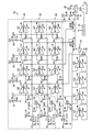
プリントヘッドを熱暴走状態から保護するのを助ける回路200を図2に示す。回路200は左ジェットスタック回路204、右ジェットスタック回路304、およびインクリザーバ回路404から成る。これらの回路の各々は本質的に他の2つの回路と同じ構造を有する。したがって、説明を簡略化するために、左ジェットスタック回路204のみをここでは記載する。各回路内では、同様の要素についての参照番号は最後の2桁は同じである。
A
左ジェットスタックサーミスタ210を、プリンタ内のプリントヘッドに取り付け、ここでその位置は、プリントヘッド内のジェットスタックの左側の温度に対応するものである。示される実施の形態では、サーミスタは負の係数のサーミスタであり、これはサーミスタの電気抵抗は温度上昇に伴って減少することを意味する。電圧源(図示せず)は電圧を提供し、この電圧は抵抗器214を通りサーミスタ210を通って降下し接地する。ノード212での電圧はプリントヘッド内の左ジェットスタックの温度に対応する。この信号は、サーミスタ210の抵抗が左ジェットスタックの温度変化によって変化するのに伴って、変化する。
A left jet stack thermistor 210 is attached to the print head in the printer, where its position corresponds to the temperature on the left side of the jet stack in the print head. In the embodiment shown, the thermistor is a negative coefficient thermistor, which means that the electrical resistance of the thermistor decreases with increasing temperature. A voltage source (not shown) provides a voltage that drops through
信号を、アナログ/デジタル変換器(ADC)218によって、プリンタのコントローラ350に入力することができるデジタル値に変換してもよい。ADC318および418のデジタル出力を、ADC218の出力と多重化し、3チャンネルの温度データをコントローラに提供してもよく、または各デジタル信号をコントローラに連続的に提供してもよい。図2の実施の形態では、信号センサ、即ちサーミスタ210、310または410の1つからの信号を、コントローラ350による温度調節制御信号としてと、回路200による防護状態信号としての両方に使用してもよい。温度調節制御は、コントローラ350が、サーミスタから受け取った電圧のデジタル値に対応する温度を用いて、トライアック356用制御信号を発生させることで実行される。制御信号は信号を変化させることでトライアック356を選択的に操作し、電源290からスイッチ292を通ってプリントヘッド内の1以上のヒータへと流れる電力量を調節する。したがって、アナログ信号をコントローラ350が処理するデジタル信号に変換し、操作モード時にプリントヘッドへの電力供給を調節する。ここで説明するような防護状況が生じた場合には、このアナログ信号はまた回路200によって処理され、スイッチ292を操作して、プリントヘッドへの電力供給を終了させる。
The signal may be converted by an analog to digital converter (ADC) 218 into a digital value that can be input to the
サーミスタ210からのアナログ信号を、入力抵抗器220、224、228および230を通して4つの電子回路に提供し、この回路は図2では比較器232、236、240および244を有して実装される。信号を、比較器232および236の反転入力と比較器240および244の非反転入力とに提供する。比較器232および236の非反転入力を、たとえば、分圧器248および252のような分圧器によって提供される基準信号に結合する。比較器240および244の反転入力を、たとえば、分圧器256および260のような分圧器によって提供される基準信号に結合する。分圧器248および252の抵抗器は、分圧器256および260によって提供される基準信号より大きい基準信号を発生する大きさにする。示される実施の形態では、分圧器248および252からの基準信号は開回路の閾値に対応し、分圧器256および260からの基準信号は過熱状態を示す温度閾値に対応する。分圧器248および252からの信号は互いにほぼ等しく、分圧器256および260からの信号は互いにほぼ等しいが、冗長比較器への基準信号は同じである必要はない。
The analog signal from the thermistor 210 is provided to four electronic circuits through
比較器232および236の出力は、ダイオード264および272を通ってノード280に結合し、比較器240および244の出力は、ダイオード268および276を通ってノード280に結合する。図2に示されるように、比較器232、236、240および244の出力はオープンコレクタ出力である。したがって、比較器の出力トランジスタは、ノード212での信号が分圧器248および252からの基準信号より大きいことに応答して、およびノード212での信号が分圧器256および260からの基準信号より小さいことに応答して、起動する。比較器の1つの出力トランジスタがオンすると、抵抗器284および288を通って降下したノード280での電圧は、起動した比較器の出力ステージを通って接地へと引き込まれる。場合によっては、この電圧をスイッチ292に提供する。正の電圧がノード280に存在する限り、スイッチ292はAC電源290からプリントヘッドのヒータに電力を提供する。ノード280での電圧が比較器の出力ステージを通って接地へと引き込まれるのに応答して、スイッチはプリントヘッド内のヒータから電力を分断する。
The outputs of
図2に示される回路では、比較器232、236、240および244は異なる基板上にある。即ち、各比較器は、他の比較器を実装するのに使用される集積回路(IC)とは別個にパッケージされた集積回路(IC)である。これによって、左側のジェットスタックの電子回路は互いに電気的に独立することができる。そして、比較器232および236は開回路信号を発生させるための冗長電子回路であり、比較器240および244は過熱信号を発生させるための冗長電子回路である。図2の回路では、1カラム内に比較器232、236、240および244の1つを有するように描画されている比較器は、左側ジェットスタック回路における比較器と同じ基板上に集積電子回路を用いて実装される。比較器294、296、298および300の各々を、電子回路が実装された4つの基板の1つの上に配置する。これらは、基板上の集積回路の破局故障を示す信号を発生させ、トランジスタ302をオンにして、トランジスタ302を通ったノード280での電圧を接地し、プリントヘッド内のヒータから電力を分断するように構成される。
In the circuit shown in FIG. 2, the
操作では、回路200に通電して、サーミスタが取り付けられたプリントヘッド内の各位置における温度に対応する信号を発生させる。この信号を4つの比較器に提供し、このとき比較器の各ペアは他の回路のペアに対する冗長回路として作動する。2つの比較器は、温度信号を開回路基準電気信号と比較し、別の2つの比較器は、温度信号を過熱基準電気信号と比較する。温度信号が過熱基準信号と等しいまたはそれを下回れば、比較器の出力ステージを起動させ、ノード280で電圧を接地し、スイッチ292はプリントヘッド内のヒータを電力から分断する。温度信号が開回路基準信号と等しいまたはそれを上回れば、比較器の出力ステージを起動させ、ノード280で電圧を接地し、スイッチ292はプリントヘッド内のヒータを電力から分断する。
In operation, the
比較器294、296、298および300のグループは、回路200を実装するのに使用される集積回路(基板)上のピン接地故障(ground pin fault)を検出するように構成される。回路200内の電子回路の1つを実装するICがもはや電気的に接地しない場合には、ある電圧が、もはや接地しない集積回路内の比較器294、296、298または300の非反転入力上に現れる。この電圧はオープングランド信号であり、抵抗器304を通って降下し、トランジスタ302をオンにする。これに応答して、トランジスタ302はノード280で電圧を接地し、スイッチ292にプリントヘッド内のヒータから電力を分断させる。
The group of
単一の温度センサからの信号を防護と温度調節機能の両方に使用することができる回路の説明を、図2に示される回路の実施の形態を用いて行っている。他の回路の実施の形態を用いてもよい。たとえば、正の温度係数のサーミスタを用いて温度信号を発生させるなら、比較器の入力および基準信号をそれに合わせて適応させて、過熱および開回路状態を検出し、電力をプリントヘッド内のヒータから分断してもよい。 A description of a circuit in which a signal from a single temperature sensor can be used for both protection and temperature regulation functions is provided using the circuit embodiment shown in FIG. Other circuit embodiments may be used. For example, if a thermistor with a positive temperature coefficient is used to generate the temperature signal, the comparator input and reference signal are adapted accordingly to detect overheating and open circuit conditions, and power is drawn from the heater in the printhead. It may be divided.
温度信号の2つの基準信号との比較もまた、上述の場合と同様に、過熱または開回路状態を確実に検出するのを助けるために、電子回路を用いた冗長比較を含むものであってもよい。「電子回路」という用語は、アクティブ型の半導体要素、たとえば、トランジスタおよび比較器と、パッシブ型の要素、たとえば、抵抗器、インダクタおよびコンデンサの両方を用いて実装される電子回路を言う。 The comparison of the temperature signal with the two reference signals may also include a redundant comparison using electronic circuitry to help reliably detect overheating or open circuit conditions, as in the case described above. Good. The term “electronic circuit” refers to an electronic circuit implemented using both active semiconductor elements, such as transistors and comparators, and passive elements, such as resistors, inductors and capacitors.
上述のシステムは、防護と電力調節の両方のために、温度に対応する信号を監視する回路を提供するものである。システムはプリントヘッド内のヒータについて記載したが、別のタイプのヒータにこの回路を使用してもよい。典型的に、標準的な熱遮断部、たとえば、ヒューズ、サーマルリンク等は大部分のヒータにとって費用効率が高い。ヒータが制約のある空間に配置され、非常に早い熱応答時間が求められる状況では、回路、たとえば、上述の回路を用いることができる。このような回路では、サーミスタを配置して、ヒータによって加熱される構造内の温度に対応する信号を発生させ、感知回路は、上述のように、ヒータへの電力を調節し、安全事故状況時、たとえば、オープングランド状態または加熱状態時には、ヒータへの電力を終了させる信号を監視するように構成される。 The system described above provides a circuit that monitors a signal corresponding to temperature for both protection and power regulation. Although the system has been described for a heater in the printhead, this circuit may be used for other types of heaters. Typically, standard heat shields, such as fuses, thermal links, etc. are cost effective for most heaters. In situations where the heater is placed in a constrained space and a very fast thermal response time is required, a circuit, such as the circuit described above, can be used. In such a circuit, a thermistor is placed to generate a signal corresponding to the temperature in the structure heated by the heater, and the sensing circuit regulates the power to the heater as described above, in the event of a safety accident. For example, in an open ground state or a heating state, a signal for ending power to the heater is monitored.
当業者は、上述の熱暴走対応方法およびシステムの特定の実現に、多くの変更を行うことができることを認識している。したがって、上述のおよび他の各種特徴および機能、またはその変更を、多くの他の異なるシステムまたは用途に適宜組み合わせてもよいと判断する。現時点で予想外のまたは想定外のその各種代替、変更、改変、改良を、後に当業者は行ってもよく、これも以下の請求の範囲によって示されることを意図するものである。 Those skilled in the art recognize that many changes can be made to the particular implementation of the thermal runaway response method and system described above. Accordingly, it is determined that the above-described and other various features and functions, or modifications thereof, may be appropriately combined with many other different systems or applications. Various substitutions, alterations, modifications, and improvements that are unforeseen or unexpected at this time may be made later by those skilled in the art, which are also intended to be indicated by the following claims.
232,236,240,244,294,296,298,300 比較器、292 スイッチ。 232, 236, 240, 244, 294, 296, 298, 300 Comparator, 292 switch.
Claims (4)
プリントヘッドの温度に対応する第1の電気信号を生成するステップと、
前記第1の電気信号を参照したプリントヘッドの熱暴走状態の検出に応答してプリントヘッドへの電力供給を終了させるように構成された第1の電子回路で、前記第1の電気信号の電圧値を監視するステップと、
前記第1の電気信号の電圧値が温度閾値に対応する電圧値を上回るのに応答して、前記第1の電子回路で過熱信号を生成するステップと、
前記第1の電気信号の電圧値に対応する温度を用いて前記プリントヘッドへ供給される電力量を調節するように構成された第2の電子回路で、前記第1の電気信号の電圧値を監視するステップと、
前記第1の電気信号の電圧値が基準信号の電圧値を上回るのに応答して、第3の電子回路で回路故障信号を生成するステップと、
前記第1の電気信号の電圧値を第4及び第5の電子回路で監視するステップと、
前記第1の電気信号の電圧値が温度閾値に対応する電圧値を上回るのに応答して、前記第4の電子回路で過熱信号を生成するステップと、
前記第1の電気信号の電圧値が第2の基準信号に対応する電圧値より大きいことに応答して、前記第5の回路で回路故障信号を生成するステップと、
前記第1の電子回路又は前記第4の電子回路で生成される過熱信号、または、前記第3の電子回路又は前記第5の電子回路で生成される回路故障信号の生成に応答して、前記第2の電子回路により、前記プリントヘッドから電力を分断するステップと、を含み、
前記第1及び第4の電子回路は、異なる集積回路で実装され、
前記第3及び第5の電子回路は、異なる集積回路で実装される、方法。 A method of controlling power supply to a print head of a printer,
Generating a first electrical signal corresponding to the temperature of the printhead;
A first electronic circuit configured to terminate power supply to the print head in response to detection of a thermal runaway state of the print head with reference to the first electrical signal , the voltage of the first electrical signal ; Monitoring the value ;
A step voltage value of the first electrical signal in response to exceeding the voltage value corresponding to the temperature threshold, to generate an overheat signal in the first electronic circuit,
A second electronic circuit configured to adjust the amount of power supplied to the print head using a temperature corresponding to the voltage value of the first electrical signal, wherein the voltage value of the first electrical signal is Monitoring step;
Generating a circuit fault signal in a third electronic circuit in response to a voltage value of the first electrical signal exceeding a voltage value of a reference signal;
Monitoring the voltage value of the first electrical signal with fourth and fifth electronic circuits;
A step voltage value of the first electrical signal in response to exceeding the voltage value corresponding to the temperature threshold, to generate an overheat signal at the fourth electronic circuit,
A step voltage value of the first electrical signal in response to greater than a voltage value corresponding to the second reference signal to generate a circuit fault signal in the circuit of the fifth,
The first electronic circuit or superheated signal generated by the fourth electronic circuit or, in response to generation of said third electronic circuit or circuit fault signal generated by the fifth electronic circuits, the Separating power from the print head by a second electronic circuit ,
The first and fourth electronic circuits are implemented in different integrated circuits;
The method wherein the third and fifth electronic circuits are implemented in different integrated circuits.
前記第1の電子回路を実装する集積回路における電気的接地損失の検出に応答して、オープングランド信号を生成するステップと、
前記オープングランド信号の生成に応答して、前記プリントヘッドから電力を分断するステップと、を含む方法。 The method of claim 1, further comprising:
Generating an open ground signal in response to detection of an electrical ground loss in an integrated circuit mounting the first electronic circuit;
Disconnecting power from the printhead in response to generation of the open ground signal.
前記第1及び第3の電子回路は、異なる集積回路で実装され、
前記方法は、さらに、
前記第1及び第3の電子回路を実装する集積回路のうち1つにおける電気的接地損失の検出に応答して、オープングランド信号を生成するステップと、
前記オープングランド信号の生成に応答して、前記プリントヘッドから電力を分断するステップと、を含む方法。 The method of claim 1, comprising:
The first and third electronic circuits are implemented in different integrated circuits;
The method further comprises:
Generating an open ground signal in response to detecting an electrical ground loss in one of the integrated circuits implementing the first and third electronic circuits;
Disconnecting power from the printhead in response to generation of the open ground signal.
第1の電気信号を監視し、第1の電子回路が、前記第1の電気信号を参照してプリントヘッドの熱暴走状態を検出するのに応答して、プリントヘッドへの電力供給を終了させるように構成された第1の電子回路と、
前記第1の電気信号の電圧値を監視し、前記第1の電気信号の電圧値に対応する温度を用いて前記プリントヘッドへ供給される電力量を調節するように構成された第2の電子回路と、
前記第1の電気信号の電圧値を監視し、第3の電子回路がプリントヘッドの熱暴走状態を検出するのに応答して、プリントヘッドへの電力供給を終了させるように構成された第3の電子回路と、
前記第1及び第3の電子回路を実装する集積回路のうち1つにおける電気的接地損失の検出に応答して、オープングランド信号を生成するように構成された第4の電子回路と、
前記第1、第3及び第4の電子回路に接続され、前記第1の電子回路及び第3の電子回路によるプリントヘッドの熱暴走状態の検出、及び、前記第4の電子回路によるオープングランド信号の生成のいずれか1つに応答して、前記プリントヘッドから電力を分断するように構成されたスイッチと、を含み、
前記第1及び第3の電子回路は、異なる集積回路で実装される、システム。 A system for monitoring power supplied to a print head in a printer,
A first electrical signal is monitored and the first electronic circuit terminates power supply to the print head in response to detecting a thermal runaway condition of the print head with reference to the first electrical signal. A first electronic circuit configured as follows:
A second electron configured to monitor a voltage value of the first electrical signal and adjust an amount of power supplied to the print head using a temperature corresponding to the voltage value of the first electrical signal; Circuit,
A third circuit configured to monitor the voltage value of the first electrical signal and terminate power supply to the printhead in response to the third electronic circuit detecting a thermal runaway condition of the printhead; Electronic circuit,
A fourth electronic circuit configured to generate an open ground signal in response to detection of an electrical ground loss in one of the integrated circuits implementing the first and third electronic circuits;
Detection of a thermal runaway state of a print head by the first electronic circuit and the third electronic circuit connected to the first, third and fourth electronic circuits, and an open ground signal by the fourth electronic circuit A switch configured to disconnect power from the printhead in response to any one of
The system, wherein the first and third electronic circuits are implemented with different integrated circuits.
Applications Claiming Priority (2)
| Application Number | Priority Date | Filing Date | Title |
|---|---|---|---|
| US12/358,923 | 2009-01-23 | ||
| US12/358,923 US8109591B2 (en) | 2009-01-23 | 2009-01-23 | System and method for protecting a printer from an over-temperature condition in a printhead |
Publications (3)
| Publication Number | Publication Date |
|---|---|
| JP2010167783A JP2010167783A (en) | 2010-08-05 |
| JP2010167783A5 JP2010167783A5 (en) | 2013-03-07 |
| JP5286296B2 true JP5286296B2 (en) | 2013-09-11 |
Family
ID=42084698
Family Applications (1)
| Application Number | Title | Priority Date | Filing Date |
|---|---|---|---|
| JP2010012248A Expired - Fee Related JP5286296B2 (en) | 2009-01-23 | 2010-01-22 | System for protecting a printer from overheating conditions in a printhead |
Country Status (7)
| Country | Link |
|---|---|
| US (2) | US8109591B2 (en) |
| EP (1) | EP2210740B1 (en) |
| JP (1) | JP5286296B2 (en) |
| KR (1) | KR101549711B1 (en) |
| CN (1) | CN101817266B (en) |
| BR (1) | BRPI1000106A2 (en) |
| MX (1) | MX2010000700A (en) |
Families Citing this family (6)
| Publication number | Priority date | Publication date | Assignee | Title |
|---|---|---|---|---|
| CN102501641B (en) * | 2011-10-10 | 2014-10-01 | 深圳市理邦精密仪器股份有限公司 | Device and method for controlling heating time of thermosensitive head |
| EP3326823B1 (en) | 2011-10-14 | 2020-12-09 | Hewlett-Packard Development Company, L.P. | Firing actuator power supply system |
| US8876256B2 (en) | 2012-02-03 | 2014-11-04 | Hewlett-Packard Development Company, L.P. | Print head die |
| US9931840B2 (en) * | 2013-08-22 | 2018-04-03 | Xerox Corporation | Systems and methods for heating and measuring temperature of print head jet stacks |
| US10566783B2 (en) | 2017-04-11 | 2020-02-18 | Intel Corporation | Methods and apparatus for implementing over-temperature fault protection in wearable devices and other electronic devices |
| WO2021225593A1 (en) * | 2020-05-06 | 2021-11-11 | Hewlett-Packard Development Company, L.P. | Determining a replacement condition for a printhead based on thermal events |
Family Cites Families (20)
| Publication number | Priority date | Publication date | Assignee | Title |
|---|---|---|---|---|
| JP2639450B2 (en) | 1987-04-28 | 1997-08-13 | 株式会社東芝 | Thermal recording device |
| JPH03136855A (en) * | 1989-10-22 | 1991-06-11 | Canon Inc | Attachment detection device of ink jet printer printing part |
| US4980702A (en) | 1989-12-28 | 1990-12-25 | Xerox Corporation | Temperature control for an ink jet printhead |
| JPH04319450A (en) * | 1991-04-18 | 1992-11-10 | Canon Inc | Recording method and device |
| US5223853A (en) | 1992-02-24 | 1993-06-29 | Xerox Corporation | Electronic spot size control in a thermal ink jet printer |
| US5585825A (en) | 1994-11-25 | 1996-12-17 | Xerox Corporation | Ink jet printer having temperature sensor for replaceable printheads |
| US5781205A (en) | 1995-04-12 | 1998-07-14 | Eastman Kodak Company | Heater power compensation for temperature in thermal printing systems |
| US5841449A (en) | 1995-04-12 | 1998-11-24 | Eastman Kodak Company | Heater power compensation for printing load in thermal printing systems |
| US5745130A (en) | 1995-12-11 | 1998-04-28 | Xerox Corporation | System for sensing the temperature of a printhead in an ink jet printer |
| US6394572B1 (en) | 1999-12-21 | 2002-05-28 | Hewlett-Packard Company | Dynamic control of printhead temperature |
| US7143500B2 (en) | 2001-06-25 | 2006-12-05 | Micron Technology, Inc. | Method to prevent damage to probe card |
| KR100419227B1 (en) | 2002-05-30 | 2004-02-21 | 삼성전자주식회사 | Device for preventing overheat of printer head |
| US6866375B2 (en) | 2002-12-16 | 2005-03-15 | Xerox Corporation | Solid phase change ink melter assembly and phase change ink image producing machine having same |
| US6966693B2 (en) | 2003-01-14 | 2005-11-22 | Hewlett-Packard Development Company, L.P. | Thermal characterization chip |
| JP2004281280A (en) | 2003-03-17 | 2004-10-07 | Ebara Densan Ltd | Full color light source and electric illumination device |
| JP4419412B2 (en) * | 2003-03-25 | 2010-02-24 | セイコーエプソン株式会社 | Head drive control device for ink jet printer |
| US7325896B2 (en) * | 2003-05-30 | 2008-02-05 | Hewlett-Packard Development Company, L.P. | Temperature calibration for fluid ejection head |
| US7182448B2 (en) | 2003-12-30 | 2007-02-27 | Xerox Corporation | Adaptive power control of ink melt heaters for uniform ink melt rate |
| KR100850711B1 (en) * | 2005-06-17 | 2008-08-06 | 삼성전자주식회사 | Method and apparatus for controlling temperature of printer head chip |
| US7870299B1 (en) * | 2008-02-06 | 2011-01-11 | Westinghouse Electric Co Llc | Advanced logic system |
-
2009
- 2009-01-23 US US12/358,923 patent/US8109591B2/en not_active Expired - Fee Related
-
2010
- 2010-01-18 MX MX2010000700A patent/MX2010000700A/en active IP Right Grant
- 2010-01-21 KR KR1020100005566A patent/KR101549711B1/en active IP Right Grant
- 2010-01-21 BR BRPI1000106-9A patent/BRPI1000106A2/en not_active IP Right Cessation
- 2010-01-21 EP EP10151299A patent/EP2210740B1/en active Active
- 2010-01-21 CN CN2010101055855A patent/CN101817266B/en not_active Expired - Fee Related
- 2010-01-22 JP JP2010012248A patent/JP5286296B2/en not_active Expired - Fee Related
-
2012
- 2012-02-02 US US13/364,628 patent/US8449066B2/en active Active
Also Published As
| Publication number | Publication date |
|---|---|
| KR101549711B1 (en) | 2015-09-02 |
| EP2210740B1 (en) | 2013-03-20 |
| KR20100086950A (en) | 2010-08-02 |
| MX2010000700A (en) | 2010-07-22 |
| US8109591B2 (en) | 2012-02-07 |
| US8449066B2 (en) | 2013-05-28 |
| US20100188456A1 (en) | 2010-07-29 |
| US20120133699A1 (en) | 2012-05-31 |
| CN101817266B (en) | 2013-06-12 |
| JP2010167783A (en) | 2010-08-05 |
| CN101817266A (en) | 2010-09-01 |
| EP2210740A1 (en) | 2010-07-28 |
| BRPI1000106A2 (en) | 2011-03-29 |
Similar Documents
| Publication | Publication Date | Title |
|---|---|---|
| JP5286296B2 (en) | System for protecting a printer from overheating conditions in a printhead | |
| US10459379B2 (en) | Heater and image heating device mounted with heater | |
| US7885557B2 (en) | Thermistor isolation technique for a ceramic fuser heater | |
| US9084294B2 (en) | Heating device and image forming apparatus | |
| KR20070104273A (en) | Variable speed printing device with mains overload prevention | |
| EP1925984B1 (en) | Image forming apparatus and power control method thereof | |
| JP5677269B2 (en) | Printing system having selective heater actuation to allow ink flow to a printhead in the printing system | |
| JP2019522950A (en) | Device with two current monitors | |
| US8027599B2 (en) | Image forming apparatus | |
| JP2003341064A (en) | Heating preventive device of printer head | |
| US8047643B2 (en) | Temperature sensor mount for melt plate | |
| US7189949B1 (en) | Power control system and method for regulating power provided to a heating device | |
| EP1443367B1 (en) | System and method of printer/copier active line current control | |
| US8385764B2 (en) | Image forming apparatus | |
| US7277654B2 (en) | Electrophotographic power supply configuration for supplying power to a fuser | |
| US20140028764A1 (en) | Heater Configuration for a Melting Device with Non-Uniform Thermal Load | |
| JP2020098297A (en) | Image forming apparatus | |
| JP2004304866A (en) | Power supply unit and image-forming apparatus | |
| JPH01196351A (en) | Recording device | |
| JP2023044523A (en) | Image forming device and electrical apparatus | |
| JP2009248521A (en) | Thermal head | |
| JP2011059326A (en) | Heating control device and image forming apparatus | |
| JPH08289469A (en) | Duplex power supply system | |
| JP2005119244A (en) | Heat transfer printer and power circuit | |
| JPS61208071A (en) | Temperature controller for electrophotographic device |
Legal Events
| Date | Code | Title | Description |
|---|---|---|---|
| A521 | Request for written amendment filed |
Free format text: JAPANESE INTERMEDIATE CODE: A523 Effective date: 20130121 |
|
| A621 | Written request for application examination |
Free format text: JAPANESE INTERMEDIATE CODE: A621 Effective date: 20130121 |
|
| A871 | Explanation of circumstances concerning accelerated examination |
Free format text: JAPANESE INTERMEDIATE CODE: A871 Effective date: 20130121 |
|
| A975 | Report on accelerated examination |
Free format text: JAPANESE INTERMEDIATE CODE: A971005 Effective date: 20130205 |
|
| A131 | Notification of reasons for refusal |
Free format text: JAPANESE INTERMEDIATE CODE: A131 Effective date: 20130305 |
|
| A521 | Request for written amendment filed |
Free format text: JAPANESE INTERMEDIATE CODE: A523 Effective date: 20130502 |
|
| TRDD | Decision of grant or rejection written | ||
| A01 | Written decision to grant a patent or to grant a registration (utility model) |
Free format text: JAPANESE INTERMEDIATE CODE: A01 Effective date: 20130528 |
|
| A61 | First payment of annual fees (during grant procedure) |
Free format text: JAPANESE INTERMEDIATE CODE: A61 Effective date: 20130603 |
|
| R150 | Certificate of patent or registration of utility model |
Ref document number: 5286296 Country of ref document: JP Free format text: JAPANESE INTERMEDIATE CODE: R150 |
|
| R250 | Receipt of annual fees |
Free format text: JAPANESE INTERMEDIATE CODE: R250 |
|
| R250 | Receipt of annual fees |
Free format text: JAPANESE INTERMEDIATE CODE: R250 |
|
| R250 | Receipt of annual fees |
Free format text: JAPANESE INTERMEDIATE CODE: R250 |
|
| R250 | Receipt of annual fees |
Free format text: JAPANESE INTERMEDIATE CODE: R250 |
|
| R250 | Receipt of annual fees |
Free format text: JAPANESE INTERMEDIATE CODE: R250 |
|
| LAPS | Cancellation because of no payment of annual fees |