JP5285851B2 - Oxadiazole derivative and light emitting element using oxadiazole derivative - Google Patents
Oxadiazole derivative and light emitting element using oxadiazole derivative Download PDFInfo
- Publication number
- JP5285851B2 JP5285851B2 JP2006349054A JP2006349054A JP5285851B2 JP 5285851 B2 JP5285851 B2 JP 5285851B2 JP 2006349054 A JP2006349054 A JP 2006349054A JP 2006349054 A JP2006349054 A JP 2006349054A JP 5285851 B2 JP5285851 B2 JP 5285851B2
- Authority
- JP
- Japan
- Prior art keywords
- light
- emitting element
- carbon atoms
- group
- oxadiazole derivative
- Prior art date
- Legal status (The legal status is an assumption and is not a legal conclusion. Google has not performed a legal analysis and makes no representation as to the accuracy of the status listed.)
- Expired - Fee Related
Links
- 0 *c1ccc2[n](*N(*)*c([o]3)nnc3I)c(ccc(*)c3)c3c2c1 Chemical compound *c1ccc2[n](*N(*)*c([o]3)nnc3I)c(ccc(*)c3)c3c2c1 0.000 description 8
- HDAYDZWOQAMFMN-UHFFFAOYSA-N C(C(C=C1)c2nnc(-c3cc(cccc4)c4cc3)[o]2)C=C1N(c1ccccc1)c(cc1)ccc1-[n]1c(cccc2)c2c2c1cccc2 Chemical compound C(C(C=C1)c2nnc(-c3cc(cccc4)c4cc3)[o]2)C=C1N(c1ccccc1)c(cc1)ccc1-[n]1c(cccc2)c2c2c1cccc2 HDAYDZWOQAMFMN-UHFFFAOYSA-N 0.000 description 1
- HPLPJRZMDJSDIN-UHFFFAOYSA-N C(C1)C=CC=C1N(C1C=CC(c2nnc(-c3ccccc3)[o]2)=CC1)c(cc1)ccc1-c(cc1)ccc1N(c1ccccc1)c1ccccc1 Chemical compound C(C1)C=CC=C1N(C1C=CC(c2nnc(-c3ccccc3)[o]2)=CC1)c(cc1)ccc1-c(cc1)ccc1N(c1ccccc1)c1ccccc1 HPLPJRZMDJSDIN-UHFFFAOYSA-N 0.000 description 1
- GYRRDVHZHIVNTG-SUKJUDMCSA-N CC([C@H](C=C1)N(c2ccccc2)c2cccc(-c3nnc(-c4ccccc4)[o]3)c2)C=C1N(c1ccccc1)c1ccccc1 Chemical compound CC([C@H](C=C1)N(c2ccccc2)c2cccc(-c3nnc(-c4ccccc4)[o]3)c2)C=C1N(c1ccccc1)c1ccccc1 GYRRDVHZHIVNTG-SUKJUDMCSA-N 0.000 description 1
- GVSMKWDDFYFQKP-UHFFFAOYSA-N CC1(C)c2cc(N(C)c(cc3c4c5cccc4)ccc3[n]5-c3ccccc3)ccc2-c2ccccc12 Chemical compound CC1(C)c2cc(N(C)c(cc3c4c5cccc4)ccc3[n]5-c3ccccc3)ccc2-c2ccccc12 GVSMKWDDFYFQKP-UHFFFAOYSA-N 0.000 description 1
- BPVSVIUOHNDTHA-UHFFFAOYSA-N CC1(C)c2cc(N(c(cc3)ccc3N(C)c3ccccc3)c(cc3)cc(C4(C)C)c3-c3c4cccc3)ccc2-c2c1cccc2 Chemical compound CC1(C)c2cc(N(c(cc3)ccc3N(C)c3ccccc3)c(cc3)cc(C4(C)C)c3-c3c4cccc3)ccc2-c2c1cccc2 BPVSVIUOHNDTHA-UHFFFAOYSA-N 0.000 description 1
- CENFPYYQDMIYCK-UHFFFAOYSA-N CC1(C=CC=CC1)c1nnc(-c(cc2)ccc2N(c2ccccc2)c2cc(N(c3ccccc3)c3ccccc3)ccc2)[o]1 Chemical compound CC1(C=CC=CC1)c1nnc(-c(cc2)ccc2N(c2ccccc2)c2cc(N(c3ccccc3)c3ccccc3)ccc2)[o]1 CENFPYYQDMIYCK-UHFFFAOYSA-N 0.000 description 1
- RZOZOTGNDDIQJV-UHFFFAOYSA-N CN(c(cc1)cc2c1-c1ccccc1C21c2ccccc2-c2ccccc12)c(cc1)cc(c2c3cccc2)c1[n]3-c1ccccc1 Chemical compound CN(c(cc1)cc2c1-c1ccccc1C21c2ccccc2-c2ccccc12)c(cc1)cc(c2c3cccc2)c1[n]3-c1ccccc1 RZOZOTGNDDIQJV-UHFFFAOYSA-N 0.000 description 1
- DIPAJEPTOAPTCE-UHFFFAOYSA-N CN(c(cc1c2c3cccc2)ccc1[n]3-c1ccccc1)c1cc2ccccc2cc1 Chemical compound CN(c(cc1c2c3cccc2)ccc1[n]3-c1ccccc1)c1cc2ccccc2cc1 DIPAJEPTOAPTCE-UHFFFAOYSA-N 0.000 description 1
- AIGNGDVKNYTOKR-UHFFFAOYSA-N CN(c1ccccc1)c(cc1c2c3cccc2)ccc1[n]3-c1ccccc1 Chemical compound CN(c1ccccc1)c(cc1c2c3cccc2)ccc1[n]3-c1ccccc1 AIGNGDVKNYTOKR-UHFFFAOYSA-N 0.000 description 1
- ZPVPABBOZJNWQG-UHFFFAOYSA-N Cc(cc1)ccc1N(C)c(cc1c2c3cccc2)ccc1[n]3-c1ccccc1 Chemical compound Cc(cc1)ccc1N(C)c(cc1c2c3cccc2)ccc1[n]3-c1ccccc1 ZPVPABBOZJNWQG-UHFFFAOYSA-N 0.000 description 1
- ZFCYCWKBJHDXJA-UHFFFAOYSA-N c(cc1)ccc1-c1nnc(-c(c2c3cccc2)ccc3N(c2ccccc2)c(cc2)ccc2N(c2ccccc2)c2ccccc2)[o]1 Chemical compound c(cc1)ccc1-c1nnc(-c(c2c3cccc2)ccc3N(c2ccccc2)c(cc2)ccc2N(c2ccccc2)c2ccccc2)[o]1 ZFCYCWKBJHDXJA-UHFFFAOYSA-N 0.000 description 1
- QFXXQRNXJVKUBM-UHFFFAOYSA-N c(cc1)ccc1-c1nnc(-c(cc2)ccc2N(c2ccccc2)c(cc2)c(cccc3)c3c2N(c2ccccc2)c2ccccc2)[o]1 Chemical compound c(cc1)ccc1-c1nnc(-c(cc2)ccc2N(c2ccccc2)c(cc2)c(cccc3)c3c2N(c2ccccc2)c2ccccc2)[o]1 QFXXQRNXJVKUBM-UHFFFAOYSA-N 0.000 description 1
- ZCWWXFJUMKVNMB-UHFFFAOYSA-N c(cc1)ccc1-c1nnc(-c(cc2)ccc2N(c2ccccc2)c2cccc3c2cccc3N(c2ccccc2)c2ccccc2)[o]1 Chemical compound c(cc1)ccc1-c1nnc(-c(cc2)ccc2N(c2ccccc2)c2cccc3c2cccc3N(c2ccccc2)c2ccccc2)[o]1 ZCWWXFJUMKVNMB-UHFFFAOYSA-N 0.000 description 1
- FSNIINXBRMRBRY-UHFFFAOYSA-N c(cc1)ccc1-c1nnc(-c(cc2)ccc2N(c2ccccc2)c2ccccc2N(c2ccccc2)c2ccccc2)[o]1 Chemical compound c(cc1)ccc1-c1nnc(-c(cc2)ccc2N(c2ccccc2)c2ccccc2N(c2ccccc2)c2ccccc2)[o]1 FSNIINXBRMRBRY-UHFFFAOYSA-N 0.000 description 1
- VYHDFRVJZMSVAA-UHFFFAOYSA-N c(cc1)ccc1-c1nnc(-c(cccc2)c2N(c2ccccc2)c(cc2)ccc2N(c2ccccc2)c2ccccc2)[o]1 Chemical compound c(cc1)ccc1-c1nnc(-c(cccc2)c2N(c2ccccc2)c(cc2)ccc2N(c2ccccc2)c2ccccc2)[o]1 VYHDFRVJZMSVAA-UHFFFAOYSA-N 0.000 description 1
- NKOHWPMWRBNXFC-UHFFFAOYSA-N c(cc1)ccc1-c1nnc(-c2c(cccc3N(c4ccccc4)c(cc4)ccc4N(c4ccccc4)c4ccccc4)c3ccc2)[o]1 Chemical compound c(cc1)ccc1-c1nnc(-c2c(cccc3N(c4ccccc4)c(cc4)ccc4N(c4ccccc4)c4ccccc4)c3ccc2)[o]1 NKOHWPMWRBNXFC-UHFFFAOYSA-N 0.000 description 1
- OKOVAOPLQWEBKT-UHFFFAOYSA-N c(cc1)ccc1N(c(cc1)ccc1-c1nnc(-c2c(cccc3)c3ccc2)[o]1)c(cc1)ccc1-[n]1c(cccc2)c2c2c1cccc2 Chemical compound c(cc1)ccc1N(c(cc1)ccc1-c1nnc(-c2c(cccc3)c3ccc2)[o]1)c(cc1)ccc1-[n]1c(cccc2)c2c2c1cccc2 OKOVAOPLQWEBKT-UHFFFAOYSA-N 0.000 description 1
Images


Description
本発明は、オキサジアゾール誘導体に関する。また本発明は、前記オキサジアゾール誘導体を用いた発光素子、発光装置、電子機器に関する。 The present invention relates to oxadiazole derivatives. The present invention also relates to a light-emitting element, a light-emitting device, and an electronic device using the oxadiazole derivative.
有機化合物は無機化合物に比べて種類が多様であり、様々な機能を有する物質を設計・合成できる可能性がある。このような利点から、近年、有機化合物を用いたエレクトロニクスに注目が集まっている。例えば、有機化合物を機能性材料として用いた太陽電池や発光素子、トランジスタ等がその代表例である。 Organic compounds are more diverse than inorganic compounds, and there is a possibility that substances having various functions can be designed and synthesized. Due to these advantages, attention has been focused on electronics using organic compounds in recent years. For example, a solar cell, a light emitting element, a transistor, and the like using an organic compound as a functional material are typical examples.
これらは有機化合物の電気物性や光物性を利用したデバイスであるが、中でも特に、有機化合物を発光物質とする発光素子の研究開発はめざましい発展を見せている。 These are devices that utilize the electrical properties and optical properties of organic compounds, and in particular, research and development of light-emitting elements using organic compounds as light-emitting substances are making remarkable progress.
この発光素子の構成は、電極間に発光物質である有機化合物を含む発光層を設けただけの単純な構造であり、薄型軽量・高速応答性・直流低電圧駆動などの特性から、次世代のフラットパネルディスプレイ素子として注目されている。また、この発光素子を用いたディスプレイは、コントラストや画質に優れ、視野角が広いという特徴も有している。 The structure of this light-emitting element is a simple structure in which a light-emitting layer containing an organic compound, which is a light-emitting substance, is provided between the electrodes. From the characteristics such as thin and light, high-speed response, and direct current low-voltage drive, It attracts attention as a flat panel display element. In addition, a display using this light-emitting element is characterized by excellent contrast and image quality and a wide viewing angle.
有機化合物を発光物質とする発光素子の発光機構は、キャリア注入型である。すなわち、電極間に発光層を挟んで電圧を印加することにより、電極から注入された正孔および電子が再結合して発光物質が励起状態となり、その励起状態が基底状態に戻る際に発光する。そして、励起状態の種類としては、一重項励起状態(S*)と三重項励起状態(T*)がある。また、発光素子におけるその統計的な生成比率は、S*:T*=1:3であると考えられている。 The light emitting mechanism of a light emitting element using an organic compound as a light emitting substance is a carrier injection type. In other words, by applying a voltage with the light emitting layer sandwiched between the electrodes, holes and electrons injected from the electrodes are recombined, and the luminescent material becomes excited, and emits light when the excited state returns to the ground state. . The types of excited states include a singlet excited state (S * ) and a triplet excited state (T * ). Further, the statistical generation ratio of the light emitting element is considered to be S * : T * = 1: 3.
一重項励起状態を発光に変換する化合物(以下、蛍光性化合物と称す)は室温において、三重項励起状態からの発光(燐光)は観測されず、一重項励起状態からの発光(蛍光)のみが観測される。したがって、蛍光性化合物を用いた発光素子における内部量子効率(注入したキャリアに対して発生するフォトンの割合)の理論的限界は、S*:T*=1:3であることを根拠に25%とされている。 A compound that converts a singlet excited state into light emission (hereinafter referred to as a fluorescent compound) does not emit light (phosphorescence) from the triplet excited state at room temperature, and only emits light (fluorescence) from the singlet excited state. Observed. Therefore, the theoretical limit of the internal quantum efficiency (ratio of photons generated with respect to injected carriers) in a light emitting device using a fluorescent compound is 25% on the basis that S * : T * = 1: 3. It is said that.
一方、三重項励起状態を発光に変換する化合物(以下、燐光性化合物と称す)を用いれば、内部量子効率は75〜100%まで理論上は可能となる。つまり、蛍光性化合物に比べて3〜4倍の発光効率が可能となる。このような理由から、高効率な発光素子を実現するために、燐光性化合物を用いた発光素子の開発が近年盛んに行われている(例えば、非特許文献1参照)。 On the other hand, if a compound that converts a triplet excited state into light emission (hereinafter referred to as a phosphorescent compound) is used, the internal quantum efficiency can be theoretically made 75 to 100%. That is, the light emission efficiency is 3 to 4 times that of the fluorescent compound. For these reasons, in order to realize a highly efficient light-emitting element, a light-emitting element using a phosphorescent compound has been actively developed in recent years (see, for example, Non-Patent Document 1).
上述した燐光性化合物を用いて発光素子の発光層を形成する場合、燐光性化合物の濃度消光や三重項−三重項消滅による消光を抑制するために、他の物質からなるマトリクス中に該燐光性化合物が分散するようにして形成することが多い。この時、マトリクスとなる物質はホスト材料、燐光性化合物のようにマトリクス中に分散される物質はゲスト材料と呼ばれる。 In the case where a light-emitting layer of a light-emitting element is formed using the above-described phosphorescent compound, in order to suppress concentration quenching of the phosphorescent compound and quenching due to triplet-triplet annihilation, the phosphorescence is included in a matrix formed of another substance. Often formed such that the compound is dispersed. At this time, a substance that becomes a matrix is called a host material, and a substance dispersed in the matrix such as a phosphorescent compound is called a guest material.
燐光性化合物をゲスト材料とする場合、ホスト材料に必要とされる性質は、該燐光性化合物よりも大きな三重項励起エネルギー(基底状態と三重項励起状態とのエネルギー差)を有することである。非特許文献1でホスト材料として用いられているCBPは、緑色〜赤色の発光を示す燐光性化合物よりも大きな三重項励起エネルギーを有していることが知られており、燐光性化合物に対するホスト材料として広く利用されている。
When a phosphorescent compound is used as a guest material, the property required for the host material is to have triplet excitation energy (energy difference between the ground state and the triplet excited state) larger than that of the phosphorescent compound. CBP used as a host material in Non-Patent
しかしながら、CBPはその大きな三重項励起エネルギーと引き替えに、正孔や電子を受け取る能力に乏しいため、駆動電圧が高くなるという問題点があった。したがって、大きな三重項励起エネルギーを有すると共に、正孔・電子の両方を受け取りやすく、また輸送できる物質(すなわちバイポーラ性を有する物質)が、燐光性化合物に対するホスト材料として求められている。 However, CBP has a problem in that the driving voltage becomes high because of its poor ability to receive holes and electrons in exchange for its large triplet excitation energy. Therefore, a substance having a large triplet excitation energy, easily accepting and transporting both holes and electrons (that is, a substance having a bipolar property) is required as a host material for a phosphorescent compound.
また、一重項励起エネルギー(基底状態と一重項励起状態とのエネルギー差)は三重項励起エネルギーよりも大きいため、大きな三重項励起エネルギーを有する物質は大きな一重項励起エネルギーをも有する。したがって、上述したような大きな三重項励起エネルギーを有すると共に、バイポーラ性を有する物質は、蛍光性化合物を発光物質として用いた発光素子においても有益である。 In addition, since the singlet excitation energy (energy difference between the ground state and the singlet excited state) is larger than the triplet excitation energy, a substance having a large triplet excitation energy also has a large singlet excitation energy. Therefore, a substance having a large triplet excitation energy and having a bipolar property as described above is also useful in a light-emitting element using a fluorescent compound as a light-emitting substance.
以上のことから、本発明では、励起エネルギーの大きな物質、特に、三重項励起エネルギーの大きな物質を提供することを課題とする。また本発明では、バイポーラ性を有する物質を提供することを課題とする。 In view of the above, an object of the present invention is to provide a substance having a large excitation energy, particularly a substance having a large triplet excitation energy. Another object of the present invention is to provide a bipolar substance.
また、このような物質を発光素子に適用することにより、発光効率の高い発光素子を提供することを課題とする。また、駆動電圧の低い発光素子を提供することを課題とする。 Another object is to provide a light-emitting element with high emission efficiency by applying such a substance to the light-emitting element. Another object is to provide a light-emitting element with low driving voltage.
さらに、上述した発光素子を用いて発光装置を作製することにより、消費電力の少ない発光装置を提供することを課題とする。また、このような発光装置を電子機器に適用することにより、消費電力の少ない電子機器を提供することを課題とする。 Furthermore, it is an object to provide a light-emitting device with low power consumption by manufacturing a light-emitting device using the above-described light-emitting element. Another object is to provide an electronic device with low power consumption by applying such a light-emitting device to the electronic device.
本発明者らは鋭意検討を重ねた結果、下記一般式(G1)で表されるオキサジアゾール誘導体が、課題を解決できることを見出した。したがって本発明の構成は、下記一般式(G1)で表されるオキサジアゾール誘導体である。 As a result of intensive studies, the present inventors have found that an oxadiazole derivative represented by the following general formula (G1) can solve the problem. Therefore, the structure of the present invention is an oxadiazole derivative represented by the following general formula (G1).

上記一般式(G1)において、置換基Amとして一般式(Am1)を適用した場合、本発明のオキサジアゾール誘導体は下記一般式(G2)で表される。したがって本発明の構成は、下記一般式(G2)で表されるオキサジアゾール誘導体である。 The general formula (G1), when applied general formula (Am1) as a substituent A m, oxadiazole derivatives of the present invention is represented by the following general formula (G2). Therefore, the structure of the present invention is an oxadiazole derivative represented by the following general formula (G2).
ここで、より大きな三重項励起エネルギーを得ると同時に、化学的な安定性も得るため、上記一般式(G2)におけるβ1はフェニレン基であることが好ましい。したがって本発明の好ましい構成は、下記一般式(G3)で表されるオキサジアゾール誘導体である。 Here, β 1 in the general formula (G2) is preferably a phenylene group in order to obtain larger triplet excitation energy and chemical stability at the same time. Therefore, a preferable structure of the present invention is an oxadiazole derivative represented by the following general formula (G3).
また、より大きな三重項励起エネルギーが得られると同時に合成も容易であるため、Ar 1は置換または無置換のフェニル基であることが好ましい。したがって本発明の他の構成は、下記一般式(G4)で表されるオキサジアゾール誘導体である。なお、αが1,2−フェニレン基、または1,3−フェニレン基、または1,4−フェニレン基である場合、安価に収率よく合成できるため好ましい。 In addition, since a larger triplet excitation energy can be obtained and synthesis is easy, A r 1 is preferably a substituted or unsubstituted phenyl group. Therefore, another structure of the present invention is an oxadiazole derivative represented by the following general formula (G4). Note that it is preferable that α is a 1,2-phenylene group, a 1,3-phenylene group, or a 1,4-phenylene group because it can be synthesized at a low cost and with a high yield.
また特に、αが1,4−フェニレン基である場合、化学的な安定性と高いキャリア輸送性が得られるため好ましい。したがって本発明の他の構成は、下記一般式(G5)で表されるオキサジアゾール誘導体である。 In particular, when α is a 1,4-phenylene group, it is preferable because chemical stability and high carrier transportability can be obtained. Therefore, another structure of the present invention is an oxadiazole derivative represented by the following general formula (G5).
さらに、Ar 2は、より大きな三重項励起エネルギーを得るために、置換または無置換のフェニル基であることが好ましい。したがって本発明の他の構成は、下記一般式(G6)で表されるオキサジアゾール誘導体である。 Further, A r 2, in order to obtain a larger triplet excitation energy, is preferably a substituted or unsubstituted phenyl group. Therefore, another structure of the present invention is an oxadiazole derivative represented by the following general formula (G6).
次に、上述の一般式(G1)において、置換基Amとして一般式(Am2)を適用した場合、本発明のオキサジアゾール誘導体は下記一般式(G7)で表される。したがって本発明の構成は、下記一般式(G7)で表されるオキサジアゾール誘導体である。 Then, the above general formula in (G1), when applied general formula (Am2) as a substituent A m, oxadiazole derivatives of the present invention is represented by the following general formula (G7). Therefore, the structure of the present invention is an oxadiazole derivative represented by the following general formula (G7).
ここで、より大きな三重項励起エネルギーが得られると同時に合成も容易であるため、Ar 1は置換または無置換のフェニル基であることが好ましい。したがって本発明の他の構成は、下記一般式(G8)で表されるオキサジアゾール誘導体である。なお、αが1,2−フェニレン基、または1,3−フェニレン基、または1,4−フェニレン基である場合、安価に収率よく合成できるため好ましい。 Here, since larger triplet excitation energy can be obtained and synthesis is easy, A r 1 is preferably a substituted or unsubstituted phenyl group. Therefore, another structure of the present invention is an oxadiazole derivative represented by the following general formula (G8). Note that it is preferable that α is a 1,2-phenylene group, a 1,3-phenylene group, or a 1,4-phenylene group because it can be synthesized at a low cost and with a high yield.
また特に、αが1,4−フェニレン基である場合、化学的な安定性と高いキャリア輸送性が得られるため好ましい。また、R3が水素である場合、合成が容易であり好ましい。したがって本発明の他の構成は、下記一般式(G9)で表されるオキサジアゾール誘導体である。 In particular, when α is a 1,4-phenylene group, it is preferable because chemical stability and high carrier transportability can be obtained. Further, when R 3 is hydrogen, synthesis is easy and it is preferable. Therefore, another structure of the present invention is an oxadiazole derivative represented by the following general formula (G9).
さらに、Ar 3は、より大きな三重項励起エネルギーを得るために、置換または無置換のフェニル基であることが好ましい。したがって本発明の他の構成は、下記一般式(G10)で表されるオキサジアゾール誘導体である。 Further, A r 3, in order to obtain a larger triplet excitation energy, is preferably a substituted or unsubstituted phenyl group. Therefore, another structure of the present invention is an oxadiazole derivative represented by the following general formula (G10).
次に、上述の一般式(G1)において、置換基Amとして一般式(Am3)を適用した場合、本発明のオキサジアゾール誘導体は下記一般式(G11)で表される。したがって本発明の構成は、下記一般式(G11)で表されるオキサジアゾール誘導体である。 Then, the above general formula in (G1), when applied general formula (Am3) as a substituent A m, oxadiazole derivatives of the present invention is represented by the following general formula (G11). Therefore, the structure of the present invention is an oxadiazole derivative represented by the following general formula (G11).
ここで、より大きな三重項励起エネルギーを得ると同時に、化学的な安定性も得るため、上記一般式(G11)におけるβ2はフェニレン基であることが好ましい。したがって本発明の好ましい構成は、下記一般式(G12)で表されるオキサジアゾール誘導体である。 Here, in order to obtain larger triplet excitation energy and at the same time obtain chemical stability, β 2 in the general formula (G11) is preferably a phenylene group. Therefore, a preferable structure of the present invention is an oxadiazole derivative represented by the following general formula (G12).
また、Ar 5およびAr 6は、より大きな三重項励起エネルギーを得るために、置換または無置換のフェニル基であることが好ましい。したがって本発明の他の構成は、下記一般式(G13)で表されるオキサジアゾール誘導体である。 In addition, A r 5 and A r 6 are preferably a substituted or unsubstituted phenyl group in order to obtain larger triplet excitation energy. Therefore, another structure of the present invention is an oxadiazole derivative represented by the following general formula (G13).
また、より大きな三重項励起エネルギーが得られると同時に合成も容易であるため、Ar 1は置換または無置換のフェニル基であることが好ましい。したがって本発明の他の構成は、下記一般式(G14)で表されるオキサジアゾール誘導体である。なお、αが1,2−フェニレン基、または1,3−フェニレン基、または1,4−フェニレン基である場合、安価に収率よく合成できるため好ましい。 In addition, since a larger triplet excitation energy can be obtained and synthesis is easy, A r 1 is preferably a substituted or unsubstituted phenyl group. Therefore, another structure of the present invention is an oxadiazole derivative represented by the following general formula (G14). Note that it is preferable that α is a 1,2-phenylene group, a 1,3-phenylene group, or a 1,4-phenylene group because it can be synthesized at a low cost and with a high yield.
また特に、αが1,4−フェニレン基である場合、化学的な安定性と高いキャリア輸送性が得られるため好ましい。また、R15〜R24が水素である場合、合成が容易であり好ましい。したがって本発明の他の構成は、下記一般式(G15)で表されるオキサジアゾール誘導体である。
In particular, when α is a 1,4-phenylene group, it is preferable because chemical stability and high carrier transportability can be obtained. Further, when
さらに、Ar 4は、より大きな三重項励起エネルギーを得るために、置換または無置換のフェニル基であることが好ましい。したがって本発明の他の構成は、下記一般式(G16)で表されるオキサジアゾール誘導体である。 Furthermore, A r 4 is preferably a substituted or unsubstituted phenyl group in order to obtain a larger triplet excitation energy. Therefore, another structure of the present invention is an oxadiazole derivative represented by the following general formula (G16).
なお、上述した一般式(G1)〜(G16)で表される本発明のオキサジアゾール誘導体において、炭素数1〜4のアルキル基としては、メチル基、エチル基、イソプロピル基、イソブチル基、tert−ブチル基等が挙げられる。また、炭素数1〜4のアルコキシ基としては、メトキシ基、エトキシ基、イソプロポキシ基、イソブトキシ基、tert−ブトキシ基等が挙げられる。また、炭素数6〜25のアリール基としては、フェニル基、o−トリル基、m−トリル基、p−トリル基、4−tert−ブチルフェニル基、1−ナフチル基、2−ナフチル基、2−ビフェニル基、3−ビフェニル基、4−ビフェニル基、99−ジメチルフルオレン−2−イル基、スピロ−9,9’−ビフルオレン−2−イル基等が挙げられる。また、炭素数6〜25のアリーレン基としては、1,2−フェニレン基、1,3−フェニレン基、1,4−フェニレン基、2,5−ジメチル−1,4−フェニレン基、1,4−ナフチレン基、1,5−ナフチレン基、4,4’−ビフェニレン基、9−ジメチルフルオレン−2,7−ジイル基、スピロ−9,9’−ビフルオレン−2,7−ジイル基等が挙げられる。 In the oxadiazole derivatives of the present invention represented by the general formulas (G1) to (G16) described above, examples of the alkyl group having 1 to 4 carbon atoms include a methyl group, an ethyl group, an isopropyl group, an isobutyl group, and a tert group. -A butyl group etc. are mentioned. Moreover, as a C1-C4 alkoxy group, a methoxy group, an ethoxy group, an isopropoxy group, an isobutoxy group, a tert-butoxy group etc. are mentioned. Examples of the aryl group having 6 to 25 carbon atoms include phenyl group, o-tolyl group, m-tolyl group, p-tolyl group, 4-tert-butylphenyl group, 1-naphthyl group, 2-naphthyl group, 2 -Biphenyl group, 3-biphenyl group, 4-biphenyl group, 99-dimethylfluoren-2-yl group, spiro-9,9'-bifluoren-2-yl group and the like can be mentioned. Examples of the arylene group having 6 to 25 carbon atoms include 1,2-phenylene group, 1,3-phenylene group, 1,4-phenylene group, 2,5-dimethyl-1,4-phenylene group, 1,4 -Naphthylene group, 1,5-naphthylene group, 4,4'-biphenylene group, 9-dimethylfluorene-2,7-diyl group, spiro-9,9'-bifluorene-2,7-diyl group, etc. .
以上で述べた一般式(G1)〜(G16)で表される本発明のオキサジアゾール誘導体は発光性を有するため、発光素子に適用することができる。したがって本発明の構成は、上述のオキサジアゾール誘導体を含む発光素子である。 Since the oxadiazole derivative of the present invention represented by the general formulas (G1) to (G16) described above has a light-emitting property, it can be applied to a light-emitting element. Therefore, the structure of the present invention is a light-emitting element including the above-described oxadiazole derivative.
また、本発明のオキサジアゾール誘導体は大きな励起エネルギーを有する。また、正孔および電子の双方を輸送できるため、発光素子における発光層のホスト材料として最適である。したがって本発明の他の構成は、上述のオキサジアゾール誘導体と発光物質とを含む発光層を有する発光素子である。 Moreover, the oxadiazole derivative of the present invention has a large excitation energy. In addition, since both holes and electrons can be transported, it is optimal as a host material for the light emitting layer in the light emitting element. Accordingly, another structure of the present invention is a light-emitting element having a light-emitting layer containing the above-described oxadiazole derivative and a light-emitting substance.
特に、本発明のオキサジアゾール誘導体は大きな三重項励起エネルギーを有することが特徴であるため、前記発光物質としては燐光性化合物が好適である。このような構成とすることで、発光効率・駆動電圧共に優れた発光素子を得ることができる。 In particular, since the oxadiazole derivative of the present invention is characterized by having large triplet excitation energy, a phosphorescent compound is suitable as the light-emitting substance. With such a structure, a light-emitting element with excellent light emission efficiency and driving voltage can be obtained.
さらに、本発明のオキサジアゾール誘導体を含む層を、発光層に接して設けた発光素子も本発明の一態様である。本発明のオキサジアゾール誘導体は大きな励起エネルギーを有するため、このような構成とすることで、発光層で生じた励起子が他の層へ拡散するのを防ぐことができる。その結果、発光効率の高い発光素子を得ることができる。 Further, a light-emitting element in which a layer containing the oxadiazole derivative of the present invention is provided in contact with the light-emitting layer is also an embodiment of the present invention. Since the oxadiazole derivative of the present invention has large excitation energy, such a configuration can prevent excitons generated in the light-emitting layer from diffusing to other layers. As a result, a light-emitting element with high emission efficiency can be obtained.
また、このようにして得られた本発明の発光素子は発光効率が高く、また駆動電圧が低いという特徴を有しているため、これを用いた発光装置(画像表示デバイスや発光デバイス)は、低消費電力を実現できる。したがって本発明は、本発明の発光素子を用いた発光装置も含むものとする。また、該発光装置を用いた電子機器も含むものとする。 In addition, since the light-emitting element of the present invention obtained in this way has the characteristics of high light emission efficiency and low driving voltage, a light-emitting device (image display device or light-emitting device) using the light-emitting element is Low power consumption can be realized. Therefore, the present invention includes a light-emitting device using the light-emitting element of the present invention. In addition, electronic devices using the light-emitting device are also included.
なお、本明細書中における発光装置とは、発光素子を用いた画像表示デバイスもしくは発光デバイスを含む。また、発光素子にコネクター、例えば異方導電性フィルムもしくはTAB(Tape Automated Bonding)テープもしくはTCP(Tape Carrier Package)が取り付けられたモジュール、TABテープやTCPの先にプリント配線板が設けられたモジュール、または発光素子にCOG(Chip On Glass)方式によりIC(集積回路)が直接実装されたモジュールも全て発光装置に含むものとする。さらに、照明器具等に用いられる発光装置も含むものとする。 Note that the light-emitting device in this specification includes an image display device or a light-emitting device using a light-emitting element. In addition, a module in which a connector such as an anisotropic conductive film or TAB (Tape Automated Bonding) tape or TCP (Tape Carrier Package) is attached to a light emitting element, a module in which a printed wiring board is provided on the end of a TAB tape or TCP, Alternatively, a module in which an IC (integrated circuit) is directly mounted on a light emitting element by a COG (Chip On Glass) method is included in the light emitting device. Furthermore, a light emitting device used for a lighting fixture or the like is also included.
本発明を実施することで、励起エネルギーの大きな物質、特に、三重項励起エネルギーの大きな物質を得ることができる。また、バイポーラ性を有する物質を得ることができる。 By implementing the present invention, a substance having a large excitation energy, particularly a substance having a large triplet excitation energy can be obtained. In addition, a bipolar substance can be obtained.
また、このような物質を発光素子に適用することにより、発光効率の高い発光素子を提供することができる。また、駆動電圧の低い発光素子を提供することができる。 In addition, by applying such a substance to a light-emitting element, a light-emitting element with high emission efficiency can be provided. In addition, a light-emitting element with low driving voltage can be provided.
さらに、上述した発光素子を用いて発光装置を作製することにより、消費電力の少ない発光装置を提供することができる。また、このような発光装置を電子機器に適用することにより、消費電力の少ない電子機器を提供することができる。 Further, by manufacturing a light-emitting device using the above-described light-emitting element, a light-emitting device with low power consumption can be provided. In addition, by applying such a light-emitting device to an electronic device, an electronic device with low power consumption can be provided.
以下では、本発明の実施の態様について図面を用いて詳細に説明する。ただし、本発明は以下の説明に限定されず、本発明の趣旨及びその範囲から逸脱することなくその形態及び詳細を様々に変更し得ることは、当業者であれば容易に理解される。したがって、本発明は以下に示す実施の形態の記載内容に限定して解釈されるものではない。 Hereinafter, embodiments of the present invention will be described in detail with reference to the drawings. However, the present invention is not limited to the following description, and it will be easily understood by those skilled in the art that modes and details can be variously changed without departing from the spirit and scope of the present invention. Therefore, the present invention should not be construed as being limited to the description of the embodiments below.
(実施形態1)
本実施形態1では、本発明のオキサジアゾール誘導体について説明する。本発明のオキサジアゾール誘導体は、下記一般式(G1)で表される。
(Embodiment 1)
In
上記一般式(G1)で表されるオキサジアゾール誘導体は、下記一般式(OXD1)で表されるハロゲン化オキサジアゾール誘導体と、下記一般式(Am1’)または(Am2’)または(Am3’)で表される2級アミンのいずれかとを、金属触媒等によりカップリングすることにより得られる。そこで、以下ではまず、下記(OXD1)の合成法について開示する。 The oxadiazole derivative represented by the general formula (G1) includes a halogenated oxadiazole derivative represented by the following general formula (OXD1), and the following general formula (Am1 ′) or (Am2 ′) or (Am3 ′). ) Is coupled with a metal catalyst or the like. Therefore, in the following, first, the following synthesis method (OXD1) will be disclosed.
≪a. ハロゲン化オキサジアゾール誘導体(OXD1)の合成法≫
上記一般式(OXD1)で表されるハロゲン化オキサジアゾール誘導体は、下記合成スキーム(a)のようにして合成することができる。すなわち、まずハロゲン化アリールカルボン酸のエステル(A)とヒドラジンとを反応させることにより、ハロゲン化アリールヒドラジド(B)を合成する。次に、ハロゲン化アリールヒドラジド(B)とアリールカルボン酸ハライド(C)とを反応させることにより、ジアシルヒドラジン誘導体(D)を得る。さらに、ジアシルヒドラジン誘導体(D)を脱水剤により脱水閉環させて、1,3,4−オキサジアゾール環を形成させることにより、ハロゲン化オキサジアゾール誘導体(OXD1)を得ることができる。なお、下記スキーム(a)中において、Rはアルキル基を表す。またαは、炭素数6〜25のアリーレン基を表す。またAr 1は、炭素数6〜25のアリール基を表す。また、X1およびX2はハロゲン基を表し、好ましくはブロモ基またはヨード基である。
≪a. Synthesis Method of Halogenated Oxadiazole Derivative (OXD1) >>
The halogenated oxadiazole derivative represented by the general formula (OXD1) can be synthesized as shown in the following synthesis scheme (a). That is, a halogenated aryl hydrazide (B) is synthesized by first reacting an ester (A) of a halogenated aryl carboxylic acid with hydrazine. Next, a halogenated aryl hydrazide (B) and an arylcarboxylic acid halide (C) are reacted to obtain a diacyl hydrazine derivative (D). Furthermore, the halogenated oxadiazole derivative (OXD1) can be obtained by dehydrating and ring-closing the diacylhydrazine derivative (D) with a dehydrating agent to form a 1,3,4-oxadiazole ring. In the following scheme (a), R represents an alkyl group. Α represents an arylene group having 6 to 25 carbon atoms. A r 1 represents an aryl group having 6 to 25 carbon atoms. X 1 and X 2 each represent a halogen group, preferably a bromo group or an iodo group.
なお、脱水剤としては、塩化ホスホリルや塩化チオニル等を用いることができる。 As the dehydrating agent, phosphoryl chloride, thionyl chloride or the like can be used.
また、ハロゲン化オキサジアゾール誘導体(OXD1)を合成する手法は上記スキーム(a)に限定されることはなく、他の公知の手法を用いることができる。 Further, the method for synthesizing the halogenated oxadiazole derivative (OXD1) is not limited to the above scheme (a), and other known methods can be used.
≪b. 2級アミン(Am1’)、(Am2’)および(Am3’)の合成法≫
次に、上述の一般式(Am1’)、(Am2’)、(Am3’)で表される各2級アミンの合成法について説明する。
≪b. Synthesis Method of Secondary Amines (Am1 ′), (Am2 ′) and (Am3 ′) >>
Next, a method for synthesizing each secondary amine represented by the general formulas (Am1 ′), (Am2 ′), and (Am3 ′) will be described.
<b1. 2級アミン(Am1’)の合成法>
上述の一般式(Am1’)で表される2級アミンは、下記合成スキーム(b1)のようにして合成することができる。すなわち、まずジハロゲン化アレーン(E)とカルバゾール誘導体(F)とを、塩基存在下にて金属触媒を用いてカップリングさせることにより、ハロゲン化アリールカルバゾール誘導体(G)を合成する。次に、ハロゲン化アリールカルバゾール誘導体(G)とアリールアミン(H)とを、塩基存在下にて金属触媒を用いてカップリングさせることにより、2級アミン(Am1’)を得ることができる。なお、下記スキーム(b1)中において、β1は炭素数6〜25のアリーレン基を表す。またAr 2は、炭素数6〜25のアリール基を表す。またR1〜R2は、水素、または炭素数1〜4のアルキル基、または炭素数6〜25のアリール基のいずれかを表す。また、X3およびX4はハロゲン基を表し、好ましくはブロモ基またはヨード基である。
<B1. Synthesis Method of Secondary Amine (Am1 ′)>
The secondary amine represented by the above general formula (Am1 ′) can be synthesized as shown in the following synthesis scheme (b1). That is, first, a halogenated arylcarbazole derivative (G) is synthesized by coupling a dihalogenated arene (E) and a carbazole derivative (F) using a metal catalyst in the presence of a base. Next, a secondary amine (Am1 ′) can be obtained by coupling the halogenated arylcarbazole derivative (G) and the arylamine (H) using a metal catalyst in the presence of a base. In the following scheme (b1), β 1 represents an arylene group having 6 to 25 carbon atoms. The A r 2 represents an aryl group having 6 to 25 carbon atoms. R 1 to R 2 each represent hydrogen, an alkyl group having 1 to 4 carbon atoms, or an aryl group having 6 to 25 carbon atoms. X 3 and X 4 each represent a halogen group, preferably a bromo group or an iodo group.
なお、塩基としては炭酸カリウム、炭酸ナトリウムなどの無機塩基や、ナトリウムtert−ブトキシド等の金属アルコキシドに代表される有機塩基を用いることができる。また、金属触媒としてはパラジウム触媒や一価の銅が挙げられ、具体的には、酢酸パラジウム、塩化パラジウム、ビス(ジベンジリデンアセトン)パラジウム(0)、ヨウ化銅(I)等が挙げられる。 As the base, an inorganic base such as potassium carbonate or sodium carbonate, or an organic base typified by metal alkoxide such as sodium tert-butoxide can be used. Examples of the metal catalyst include a palladium catalyst and monovalent copper. Specific examples include palladium acetate, palladium chloride, bis (dibenzylideneacetone) palladium (0), and copper (I) iodide.
また、2級アミン(Am1’)を合成する手法は上記スキーム(b1)に限定されることはなく、他の公知の手法を用いることができる。 Further, the method for synthesizing the secondary amine (Am1 ′) is not limited to the above scheme (b1), and other known methods can be used.
<b2. 2級アミン(Am2’)の合成法>
上述の一般式(Am2’)で表される2級アミンは、下記合成スキーム(b2)のようにして合成することができる。すなわち、まずカルバゾール誘導体(I)の3位をハロゲン化剤によりハロゲン化することで、ハロゲン化カルバゾール誘導体(J)を合成する。次に、ハロゲン化カルバゾール誘導体(J)とアリールアミン(K)とを、塩基存在下にて金属触媒を用いてカップリングさせることにより、2級アミン(Am2’)を得ることができる。なお、下記スキーム(b2)中において、Ar 3は炭素数6〜25のアリール基を表す。またR3は、水素、または炭素数1〜4のアルキル基、または炭素数6〜25のアリール基のいずれかを表す。またR4は、炭素数1〜4のアルキル基、または炭素数6〜25のアリール基のいずれかを表す。またX5はハロゲン基を表し、好ましくはブロモ基またはヨード基である。
<B2. Synthesis Method of Secondary Amine (Am2 ′)>
The secondary amine represented by the above general formula (Am2 ′) can be synthesized as shown in the following synthesis scheme (b2). That is, first, the halogenated carbazole derivative (J) is synthesized by halogenating the 3-position of the carbazole derivative (I) with a halogenating agent. Next, the secondary amine (Am2 ′) can be obtained by coupling the halogenated carbazole derivative (J) and the arylamine (K) using a metal catalyst in the presence of a base. Note that in the following scheme (b2), A r 3 represents an aryl group having 6 to 25 carbon atoms. R 3 represents hydrogen, an alkyl group having 1 to 4 carbon atoms, or an aryl group having 6 to 25 carbon atoms. R 4 represents either an alkyl group having 1 to 4 carbon atoms or an aryl group having 6 to 25 carbon atoms. X 5 represents a halogen group, preferably a bromo group or an iodo group.
なお、ハロゲン化剤としては、N−ブロモスクシンイミド(NBS)やN−ヨードスクシンイミド(NIS)等を用いることができる。また、塩基および金属触媒としては、先の<b1. 2級アミン(Am1’)の合成法>で列挙したものを用いることができる。 As the halogenating agent, N-bromosuccinimide (NBS), N-iodosuccinimide (NIS), or the like can be used. As the base and metal catalyst, the above <b1. Those enumerated in <Method for synthesizing secondary amine (Am1 ')> can be used.
また、2級アミン(Am2’)を合成する手法は上記スキーム(b2)に限定されることはなく、他の公知の手法を用いることができる。 In addition, the method for synthesizing the secondary amine (Am2 ′) is not limited to the above scheme (b2), and other known methods can be used.
<b3. 2級アミン(Am3’)の合成法>
上述の一般式(Am3’)で表される2級アミンは、下記合成スキーム(b3)のようにして合成することができる。すなわち、まずトリアリールアミン(L)をハロゲン化剤によりハロゲン化することで、モノハロゲン化トリアリールアミン(M)を合成する。次に、モノハロゲン化トリアリールアミン(M)とアリールアミン(N)とを、塩基存在下にて金属触媒を用いてカップリングさせることにより、2級アミン(Am3’)を得ることができる。なお、下記スキーム(b3)中において、β2は炭素数6〜25のアリーレン基を表す。またAr 4〜Ar 6は、炭素数6〜25のアリール基を表す。またX6はハロゲン基を表し、好ましくはブロモ基またはヨード基である。
<B3. Synthesis Method of Secondary Amine (Am3 ′)>
The secondary amine represented by the above general formula (Am3 ′) can be synthesized as shown in the following synthesis scheme (b3). That is, first, a triarylamine (L) is halogenated with a halogenating agent to synthesize a monohalogenated triarylamine (M). Next, a secondary amine (Am3 ′) can be obtained by coupling a monohalogenated triarylamine (M) and an arylamine (N) using a metal catalyst in the presence of a base. Note that in the following scheme (b3), β 2 represents an arylene group having 6 to 25 carbon atoms. A r 4 to A r 6 represent an aryl group having 6 to 25 carbon atoms. X 6 represents a halogen group, preferably a bromo group or an iodo group.
なお、ハロゲン化剤としては、N−ブロモスクシンイミド(NBS)やN−ヨードスクシンイミド(NIS)等を用いることができる。また、塩基および金属触媒としては、先の<b1. 2級アミン(Am1’)の合成法>で列挙したものを用いることができる。 As the halogenating agent, N-bromosuccinimide (NBS), N-iodosuccinimide (NIS), or the like can be used. As the base and metal catalyst, the above <b1. Those enumerated in <Method for synthesizing secondary amine (Am1 ')> can be used.
また、2級アミン(Am3’)を合成する手法は上記スキーム(b3)に限定されることはなく、他の公知の手法を用いることができる。 The method for synthesizing the secondary amine (Am3 ′) is not limited to the above scheme (b3), and other known methods can be used.
≪c. 一般式(G1)で表される本発明のオキサジアゾール誘導体の合成法≫
上述のスキーム(a)で得られたハロゲン化オキサジアゾール誘導体(OXD1)と、上述のスキーム(b1)〜(b3)で得られた2級アミン(Am1’)または(Am2’)または(Am3’)のいずれかとを、塩基存在下にて金属触媒を用いてカップリングさせることにより、一般式(G1)で表される本発明のオキサジアゾール誘導体が得られる。スキームを下記スキーム(c)に示す。なお、下記スキーム(c)中において、Amは、一般式(Am1)、または(Am2)、または(Am3)のいずれかで表される置換基である。また、α、β1、β2は、炭素数6〜25のアリーレン基を表す。またAr 1〜Ar 6は、炭素数6〜25のアリール基を表す。またR1〜R3は、水素、または炭素数1〜4のアルキル基、または炭素数6〜25のアリール基のいずれかを表す。またR4は、炭素数1〜4のアルキル基、または炭素数6〜25のアリール基のいずれかを表す。またX1は、ハロゲン基を表し、好ましくはブロモ基またはヨード基である。
≪c. Synthesis Method of Oxadiazole Derivative Represented by General Formula (G1) >>
The halogenated oxadiazole derivative (OXD1) obtained in the above scheme (a) and the secondary amine (Am1 ′) or (Am2 ′) or (Am3) obtained in the above schemes (b1) to (b3). The oxadiazole derivative of the present invention represented by the general formula (G1) is obtained by coupling any of ') with a metal catalyst in the presence of a base. The scheme is shown in the following scheme (c). Note that in the following scheme (c), A m of the general formula (Am1), or (Am2), or (Am3) is a substituent represented by any one of the. Moreover, (alpha), (beta) 1 , (beta) 2 represents a C6-C25 arylene group. A r 1 to A r 6 represent an aryl group having 6 to 25 carbon atoms. R 1 to R 3 each represent hydrogen, an alkyl group having 1 to 4 carbon atoms, or an aryl group having 6 to 25 carbon atoms. R 4 represents either an alkyl group having 1 to 4 carbon atoms or an aryl group having 6 to 25 carbon atoms. X 1 represents a halogen group, preferably a bromo group or an iodo group.
なお、塩基および金属触媒としては、先の<b1. 2級アミン(Am1’)の合成法>で列挙したものを用いることができる。 As the base and metal catalyst, the above <b1. Those enumerated in <Method for synthesizing secondary amine (Am1 ')> can be used.
なお、(OXD1)と(Am1’)をカップリングしたものが上述の一般式(G2)のオキサジアゾール誘導体に該当し、(OXD1)と(Am2’)をカップリングしたものが上述の一般式(G7)のオキサジアゾール誘導体に該当し、(OXD1)と(Am3’)をカップリングしたものが上述の一般式(G11)のオキサジアゾール誘導体に該当する。 A combination of (OXD1) and (Am1 ′) corresponds to the oxadiazole derivative of the above general formula (G2), and a combination of (OXD1) and (Am2 ′) is the above general formula. This corresponds to the oxadiazole derivative of (G7), and a combination of (OXD1) and (Am3 ′) corresponds to the oxadiazole derivative of the above general formula (G11).
≪一般式(G1)で表される本発明のオキサジアゾール誘導体の具体的な構造式≫
次に、下記一般式(G1)を用いて、本発明のオキサジアゾール誘導体の具体的な構造について説明する。
<< Specific Structural Formula of Oxadiazole Derivative Represented by General Formula (G1) >>
Next, a specific structure of the oxadiazole derivative of the present invention will be described using the following general formula (G1).
まず、一般式(G1)におけるアリーレン基αの構造として、より具体的には、下記構造式群(α)に示したいずれかの構造を適用することができる。ただし、本発明はこれらに限定されることはない。 First, as the structure of the arylene group α in the general formula (G1), more specifically, any structure shown in the following structural formula group (α) can be applied. However, the present invention is not limited to these.
また、一般式(G1)におけるアリール基Ar 1の構造として、より具体的には、下記構造式群(Ar)に示したいずれかの構造を適用することができる。ただし、本発明はこれらに限定されることはない。 As the structure of the aryl group A r 1 in the general formula (G1), more specifically, any structure shown in the following structural formula group (A r ) can be applied. However, the present invention is not limited to these.
次に、一般式(G1)における置換基Amについて説明する。置換基Amは、上記一般式(G1)中に示したように(Am1)、または(Am2)、または(Am3)のいずれかで表されるが、より具体的には、下記構造式群(Am1−1)〜(Am1−10)、または構造式群(Am2−1)〜(Am2−5)、または構造式群(Am3−1)〜(Am3−9)のいずれかの構造を適用することができる。ただし、本発明はこれらに限定されることはない。 Next, a description will be given substituent A m in the general formula (G1). Substituent A m, as shown in the above general formula (G1) (Am1), or (Am2), or is represented by any one of (Am3), more specifically, the following structural formula group Any structure of (Am1-1) to (Am1-10), structural formula group (Am2-1) to (Am2-5), or structural formula group (Am3-1) to (Am3-9) is applied can do. However, the present invention is not limited to these.
以上で述べたような構造式群(α)、構造式群(Ar)、構造式群(Am1−1)〜(Am1−10)、構造式群(Am2−1)〜(Am2−5)、構造式群(Am3−1)〜(Am3−9)を適宜組み合わせることにより、本発明のオキサジアゾール誘導体は構成されるが、以下では、本発明のオキサジアゾール誘導体の具体的な構造式を列挙する(下記構造式(1)〜(140))。ただし、本発明はこれらに限定されることはない。 Structural formula group (α), structural formula group (A r ), structural formula groups (Am1-1) to (Am1-10), structural formula groups (Am2-1) to (Am2-5) as described above The oxadiazole derivatives of the present invention are constituted by appropriately combining the structural formula groups (Am3-1) to (Am3-9). Hereinafter, specific structural formulas of the oxadiazole derivatives of the present invention will be described. Are listed (the following structural formulas (1) to (140)). However, the present invention is not limited to these.
(実施形態2)
本実施形態2では、実施形態1で述べた本発明のオキサジアゾール誘導体を発光層のホスト材料として用いた発光素子の態様について、図1を用いて説明する。
(Embodiment 2)
In
図1は、第1の電極101と第2の電極102との間に発光層113を有する発光素子を示した図である。そして発光層113は、本発明のオキサジアゾール誘導体と発光物質とを含む層である。本実施形態2においては、本発明のオキサジアゾール誘導体は発光層113におけるホスト材料であり、発光物質がゲスト材料である。
FIG. 1 is a diagram illustrating a light-emitting element having a light-emitting
このような発光素子に対して電圧を印加することにより、第1の電極101側から注入された正孔と第2の電極102側から注入された電子とが、発光層113において再結合し、発光物質が励起状態になる。そして、励起状態の該発光物質が基底状態に戻る際に発光する。本発明のオキサジアゾール誘導体はバイポーラ性を有するため、正孔および電子の両方を効率良く受け取り、発光物質に輸送することができる。したがって、本発明の発光素子は、低い駆動電圧で発光物質の励起状態を生成することができる。また、本発明のオキサジアゾール誘導体は励起エネルギーが大きいため、励起状態となった発光物質は消光されることなく、効率良く発光に至ることができる。なお、本実施形態2の発光素子において、第1の電極101は陽極として機能し、第2の電極102は陰極として機能する。
By applying a voltage to such a light-emitting element, holes injected from the
発光物質(すなわちゲスト材料)について特に限定はないが、本発明のオキサジアゾール誘導体は大きな三重項励起エネルギーを有しているため、ゲスト材料は燐光性化合物が好ましい。具体的には、ビス[2−(4’,6’−ジフルオロフェニル)ピリジナト−N,C2’]イリジウム(III)ピコリナート(略称:FIrpic)、トリス(2−フェニルピリジナト−N,C2’)イリジウム(III)(略称:Ir(ppy)3)、ビス(2−フェニルピリジナト−N,C2’)イリジウム(III)アセチルアセトナート(略称:Ir(ppy)2(acac))、ビス(2−フェニルベンゾチアゾラト−N,C2’)イリジウム(III)アセチルアセトナート(略称:Ir(bt)2(acac))、トリス(2−フェニルキノリナト−N,C2’)イリジウム(III)(略称:Ir(pq)3)、ビス(2−フェニルキノリナト−N,C2’)イリジウム(III)アセチルアセトナート(略称:Ir(pq)2(acac))、ビス[2−(2’−ベンゾ[4,5−α]チエニル)ピリジナト−N,C3’]イリジウム(III)アセチルアセトナート(略称:Ir(btp)2(acac))、ビス(1−フェニルイソキノリナト−N,C2’)イリジウム(III)アセチルアセトナート(略称:Ir(piq)2(acac))、(アセチルアセトナト)ビス[2,3−ビス(4−フルオロフェニル)キノキサリナト]イリジウム(III)(略称:Ir(Fdpq)2(acac))、2,3,7,8,12,13,17,18−オクタエチル−21H,23H−ポルフィリン白金(II)(略称:PtOEP)等が挙げられる。 There is no particular limitation on the light-emitting substance (that is, the guest material); however, since the oxadiazole derivative of the present invention has large triplet excitation energy, the guest material is preferably a phosphorescent compound. Specifically, bis [2- (4 ′, 6′-difluorophenyl) pyridinato-N, C 2 ′ ] iridium (III) picolinate (abbreviation: FIrpic), tris (2-phenylpyridinato-N, C 2 ′ ) iridium (III) (abbreviation: Ir (ppy) 3 ), bis (2-phenylpyridinato-N, C 2 ′ ) iridium (III) acetylacetonate (abbreviation: Ir (ppy) 2 (acac)) ), Bis (2-phenylbenzothiazolate-N, C 2 ′ ) iridium (III) acetylacetonate (abbreviation: Ir (bt) 2 (acac)), tris (2-phenylquinolinato-N, C2 ′) ) iridium (III) (abbreviation: Ir (pq) 3), bis (2-phenylquinolinato--N, C2 ') iridium (III) acetylacetonate (abbreviation: Ir (pq 2 (acac)), bis [2- (2'-benzo [4, 5-alpha] thienyl) pyridinato -N, C 3 '] iridium (III) acetylacetonate (abbreviation: Ir (btp) 2 (acac) ), Bis (1-phenylisoquinolinato-N, C2 ′) iridium (III) acetylacetonate (abbreviation: Ir (piq) 2 (acac)), (acetylacetonato) bis [2,3-bis (4 -Fluorophenyl) quinoxalinato] iridium (III) (abbreviation: Ir (Fdpq) 2 (acac)), 2,3,7,8,12,13,17,18-octaethyl-21H, 23H-porphyrin platinum (II) (Abbreviation: PtOEP).
また、発光物質としては蛍光性化合物を用いることもでき、具体的には、ペリレン、2,5,8,11−テトラ(tert−ブチル)ペリレン(略称:TBP)、4,4’−ビス[2−(N−エチルカルバゾール−3−イル)ビニル]ビフェニル(略称:BCzVBi)、5,12−ジフェニルテトラセン、N,N’−ジメチルキナクリドン(略称:DMQd)、N,N’−ジフェニルキナクリドン(略称:DMQd)、4−ジシアノメチレン−2−イソプロピル−6−[2−(1,1,7,7−テトラメチルジュロリジン−9−イル)エテニル]−4H−ピラン(略称:DCJTI)、ルブレン、クマリン6、クマリン30等が挙げられる。
As the light-emitting substance, a fluorescent compound can be used. Specifically, perylene, 2,5,8,11-tetra (tert-butyl) perylene (abbreviation: TBP), 4,4′-bis [ 2- (N-ethylcarbazol-3-yl) vinyl] biphenyl (abbreviation: BCzVBi), 5,12-diphenyltetracene, N, N′-dimethylquinacridone (abbreviation: DMQd), N, N′-diphenylquinacridone (abbreviation) : DMQd), 4-dicyanomethylene-2-isopropyl-6- [2- (1,1,7,7-tetramethyljulolidin-9-yl) ethenyl] -4H-pyran (abbreviation: DCJTI), rubrene,
第1の電極101について特に限定はないが、本実施形態2のように、陽極として機能する際は仕事関数の大きい物質で形成されていることが好ましい。具体的には、インジウム錫酸化物(ITO)、または酸化珪素を含むインジウム錫酸化物(ITSO)、2〜20wt%の酸化亜鉛を含む酸化インジウム(IZO)の他、金(Au)、白金(Pt)、ニッケル(Ni)、タングステン(W)、クロム(Cr)、モリブデン(Mo)、鉄(Fe)、コバルト(Co)、銅(Cu)、パラジウム(Pd)等を用いることができる。なお、第1の電極101は、例えばスパッタ法や蒸着法等を用いて形成することができる。
Although there is no particular limitation on the
また、第2の電極102について特に限定はないが、本実施形態2のように、陰極として機能する際は仕事関数の小さい物質で形成されていることが好ましい。具体的には、アルミニウム(Al)やインジウム(In)の他、リチウム(Li)やセシウム(Cs)等のアルカリ金属、マグネシウム(Mg)やカルシウム(Ca)等のアルカリ土類金属、エルビウム(Er)やイッテルビウム(Yb)等の希土類金属を用いることができる。また、アルミニウムリチウム合金(AlLi)やマグネシウム銀合金(MgAg)のような合金を用いることもできる。なお、第2の電極102は、例えばスパッタ法や蒸着法等を用いて形成することができる。
Although there is no particular limitation on the
なお、発光した光を外部に取り出すために、第1の電極101と第2の電極102のいずれか一または両方は、ITO等の可視光を透過する導電膜から成る電極、または可視光を透過出来るように数〜数十nmの厚さで形成された電極であることが好ましい。
Note that in order to extract emitted light to the outside, one or both of the
また、第1の電極101と発光層113との間には、図1に示すように正孔輸送層112を設けてもよい。ここで、正孔輸送層とは、第1の電極101から注入された正孔を発光層113へ輸送する機能を有する層である。このように、正孔輸送層112を設け、第1の電極101と発光層113とを離すことによって、発光が金属に起因して消光することを防ぐことができる。ただし、正孔輸送層112は必ずしも必要ではない。
Further, a hole transport layer 112 may be provided between the
正孔輸送層112を構成する物質について特に限定はないが、代表的には、4,4’−ビス[N−(1−ナフチル)−N−フェニルアミノ]ビフェニル(略称:NPB)、4,4’−ビス[N−(3−メチルフェニル)−N−フェニルアミノ]ビフェニル(略称:TPD)、4,4’−ビス[N−(9,9−ジメチルフルオレン−2−イル)−N−フェニルアミノ]ビフェニル(略称:DFLDPBi)、4,4’,4’’−トリス(N,N−ジフェニルアミノ)トリフェニルアミン(略称:TDATA)、4,4’,4’’−トリス[N−(3−メチルフェニル)−N−フェニルアミノ]トリフェニルアミン(略称:m−MTDATA)などの芳香族アミン化合物を用いることができる。また、ポリ(4−ビニルトリフェニルアミン)(略称:PVTPA)などの高分子化合物を用いることもできる。 There is no particular limitation on a substance included in the hole-transport layer 112; typically, 4,4′-bis [N- (1-naphthyl) -N-phenylamino] biphenyl (abbreviation: NPB), 4, 4′-bis [N- (3-methylphenyl) -N-phenylamino] biphenyl (abbreviation: TPD), 4,4′-bis [N- (9,9-dimethylfluoren-2-yl) -N— Phenylamino] biphenyl (abbreviation: DFLDPBi), 4,4 ′, 4 ″ -tris (N, N-diphenylamino) triphenylamine (abbreviation: TDATA), 4,4 ′, 4 ″ -tris [N— An aromatic amine compound such as (3-methylphenyl) -N-phenylamino] triphenylamine (abbreviation: m-MTDATA) can be used. Alternatively, a high molecular compound such as poly (4-vinyltriphenylamine) (abbreviation: PVTPA) can be used.
なお、正孔輸送層112は、二層以上の層を積層して形成された多層構造であってもよい。また、二種類以上の物質を混合して形成してもよい。 Note that the hole transport layer 112 may have a multilayer structure formed by stacking two or more layers. Further, two or more kinds of substances may be mixed and formed.
また、第2の電極102と発光層113との間には、図1に示すように電子輸送層114を設けてもよい。ここで、電子輸送層とは、第2の電極102から注入された電子を発光層113へ輸送する機能を有する層である。このように、電子輸送層114を設け、第2の電極102と発光層113とを離すことによって、発光が金属に起因して消光することを防ぐことができる。ただし、電子輸送層114は必ずしも必要ではない。
Further, an
電子輸送層114を構成する物質について特に限定はないが、代表的には、トリス(8−キノリノラト)アルミニウム(略称:Alq3)、トリス(4−メチル−8−キノリノラト)アルミニウム(略称:Almq3)、ビス(10−ヒドロキシベンゾ[h]キノリナト)ベリリウム(略称:BeBq2)、ビス(2−メチル−8−キノリノラト)(4−フェニルフェノラト)アルミニウム(略称:BAlq)、ビス[2−(2−ヒドロキシフェニル)ベンズオキサゾラト]亜鉛(略称:Zn(BOX)2)、ビス[2−(2−ヒドロキシフェニル)ベンゾチアゾラト]亜鉛(略称:Zn(BTZ)2)などの金属錯体が挙げられる。また、2−(4−ビフェニリル)−5−(4−tert−ブチルフェニル)−1,3,4−オキサジアゾール(略称:PBD)、1,3−ビス[5−(p−tert−ブチルフェニル)−1,3,4−オキサジアゾール−2−イル]ベンゼン(略称:OXD−7)、3−(4−tert−ブチルフェニル)−4−フェニル−5−(4−ビフェニリル)−1,2,4−トリアゾール(略称:TAZ)、3−(4−tert−ブチルフェニル)−4−(4−エチルフェニル)−5−(4−ビフェニリル)−1,2,4−トリアゾール(略称:p−EtTAZ)、バソフェナントロリン(略称:BPhen)、バソキュプロイン(略称:BCP)、4,4’−ビス(5−メチルベンゾオキサゾール−2−イル)スチルベン(略称:BzOs)などの複素芳香族化合物も用いることができる。また、ポリ(2,5−ピリジン−ジイル)(略称:PPy)のような高分子化合物を用いることもできる。 Although there is no particular limitation on a substance included in the electron-transport layer 114, typically, tris (8-quinolinolato) aluminum (abbreviation: Alq 3 ), tris (4-methyl-8-quinolinolato) aluminum (abbreviation: Almq 3). ), Bis (10-hydroxybenzo [h] quinolinato) beryllium (abbreviation: BeBq 2 ), bis (2-methyl-8-quinolinolato) (4-phenylphenolato) aluminum (abbreviation: BAlq), bis [2- ( Metal complexes such as 2-hydroxyphenyl) benzoxazolate] zinc (abbreviation: Zn (BOX) 2 ) and bis [2- (2-hydroxyphenyl) benzothiazolate] zinc (abbreviation: Zn (BTZ) 2 ). . 2- (4-biphenylyl) -5- (4-tert-butylphenyl) -1,3,4-oxadiazole (abbreviation: PBD), 1,3-bis [5- (p-tert-butyl) Phenyl) -1,3,4-oxadiazol-2-yl] benzene (abbreviation: OXD-7), 3- (4-tert-butylphenyl) -4-phenyl-5- (4-biphenylyl) -1 , 2,4-triazole (abbreviation: TAZ), 3- (4-tert-butylphenyl) -4- (4-ethylphenyl) -5- (4-biphenylyl) -1,2,4-triazole (abbreviation: p-EtTAZ), bathophenanthroline (abbreviation: BPhen), bathocuproin (abbreviation: BCP), 4,4′-bis (5-methylbenzoxazol-2-yl) stilbene (abbreviation: BzOs), etc. Aromatic aromatic compounds can also be used. Alternatively, a high molecular compound such as poly (2,5-pyridine-diyl) (abbreviation: PPy) can be used.
なお、電子輸送層114は、二層以上の層を積層して形成された多層構造であってもよい。また、二種類以上の物質を混合して形成してもよい。
Note that the
さらに、第1の電極101と正孔輸送層112との間には、図1に示すように正孔注入層111を設けてもよい。ここで、正孔注入層とは、陽極として機能する電極から正孔輸送層112へ正孔の注入を補助する機能を有する層である。ただし、正孔注入層111は必ずしも必要ではない。
Further, a
正孔注入層111を構成する物質について特に限定はないが、バナジウム酸化物(VOx)、ニオブ酸化物(NbOx)、タンタル酸化物(TaOx)、クロム酸化物(CrOx)、モリブデン酸化物(MoOx)、タングステン酸化物(WOx)、マンガン酸化物(MnOx)、レニウム酸化物(ReOx)、ルテニウム酸化物(RuOx)等の金属酸化物を用いることができる。また、フタロシアニン(略称:H2Pc)や銅フタロシアニン(CuPC)等のフタロシアニン化合物を用いることができる。また、上述した正孔輸送層112を構成する物質を用いることもできる。また、ポリ(エチレンジオキシチオフェン)とポリ(スチレンスルホン酸)の混合物(略称:PEDOT/PSS)のような高分子化合物を用いることもできる。
Although there is no particular limitation on the substance constituting the
あるいは、正孔注入層111に、有機化合物と電子受容体とを混合してなる複合材料を用いてもよい。このような複合材料は、電子受容体によって有機化合物に正孔が発生するため、正孔注入性および正孔輸送性に優れている。この場合、有機化合物としては、発生した正孔の輸送に優れた材料であることが好ましく、具体的には、例えば上述した正孔輸送層112を構成する物質(芳香族アミン化合物等)を用いることができる。電子受容体としては、有機化合物に対し電子受容性を示す物質であればよい。具体的には、遷移金属酸化物であることが好ましく、例えば、バナジウム酸化物(VOx)、ニオブ酸化物(NbOx)、タンタル酸化物(TaOx)、クロム酸化物(CrOx)、モリブデン酸化物(MoOx)、タングステン酸化物(WOx)、マンガン酸化物(MnOx)、レニウム酸化物(ReOx)、ルテニウム酸化物(RuOx)等が挙げられる。また、塩化鉄(III)、塩化アルミニウム(III)のようなルイス酸を用いることもできる。また、7,7,8,8−テトラシアノ−2,3,5,6−テトラフルオロキノジメタン(略称:F4−TCNQ)等の有機化合物を用いることもできる。
Alternatively, a composite material obtained by mixing an organic compound and an electron acceptor may be used for the
なお、正孔注入層111は、二層以上の層を積層して形成された多層構造であってもよい。また、二種類以上の物質を混合して形成してもよい。
Note that the
また、第2の電極102と電子輸送層114との間には、図1に示すように電子注入層115を設けてもよい。ここで、電子注入層とは、陰極として機能する電極から電子輸送層114へ電子の注入を補助する機能を有する層である。ただし、電子注入層115は必ずしも必要ではない。
Further, an
電子注入層115を構成する物質について特に限定はないが、フッ化リチウム(LiF)、フッ化セシウム(CsF)、フッ化カルシウム(CaF2)、リチウム酸化物(LiOx)のようなアルカリ金属化合物またはアルカリ土類金属化合物を用いることができる。また、フッ化エルビウム(ErF3)のような希土類金属化合物を用いることができる。また、上述した電子輸送層114を構成する物質を用いることもできる。
Although there is no particular limitation on the substance constituting the
あるいは、電子注入層115に、有機化合物と電子供与体とを混合してなる複合材料を用いてもよい。このような複合材料は、電子供与体によって有機化合物に電子が発生するため、電子注入性および電子輸送性に優れている。この場合、有機化合物としては、発生した電子の輸送に優れた材料であることが好ましく、具体的には、例えば上述した電子輸送層114を構成する物質(金属錯体や複素芳香族化合物等)を用いることができる。電子供与体としては、有機化合物に対し電子供与性を示す物質であればよい。具体的には、アルカリ金属やアルカリ土類金属や希土類金属が好ましく、リチウム、セシウム、マグネシウム、カルシウム、エルビウム、イッテルビウム等が挙げられる。また、アルカリ金蔵化合物やアルカリ土類金属化合物が好ましく、リチウム酸化物(LiOx)、カルシウム酸化物(CaOx)、バリウム酸化物(BaOx)、炭酸セシウム(Cs2CO3)等が挙げられる。また、酸化マグネシウムのようなルイス塩基を用いることもできる。また、テトラチアフルバレン(略称:TTF)等の有機化合物を用いることもできる。
Alternatively, a composite material obtained by mixing an organic compound and an electron donor may be used for the
以上で述べた本発明の発光素子において、正孔注入層111、正孔輸送層112、発光層113、電子輸送層114、電子注入層115は、それぞれ、蒸着法、またはインクジェット法、または塗布法等、いずれの方法で形成しても構わない。また、第1の電極101または第2の電極102についても、スパッタリング法、蒸着法等、インクジェット法、または塗布法等、いずれの方法を用いて形成しても構わない。
In the light-emitting element of the present invention described above, the
(実施形態3)
本実施形態3では、本発明のオキサジアゾール誘導体をエキシトンブロック層として用いた発光素子の態様について、図2および図3を用いて説明する。なお、エキシトンブロック層とは、発光層に接して設けられる正孔輸送層や電子輸送層の一種であるが、特に励起エネルギーが発光層の励起エネルギーよりも大きく、発光層における励起子が他の層に移動しないようにブロックする機能を有する層である。
(Embodiment 3)
In
図2で示した発光素子においては、陽極として機能する第1の電極201と陰極として機能する第2の電極202との間に、発光層213が設けられている。そして、発光層213の陽極側に接して、本発明のオキサジアゾール誘導体からなるエキシトンブロック層220aが設けられている。したがって図2の場合、エキシトンブロック層220aは正孔輸送層の一種である。
In the light-emitting element shown in FIG. 2, a light-emitting
また、図3で示した発光素子においては、陽極として機能する第1の電極201と陰極として機能する第2の電極202との間に、発光層213が設けられている。そして、発光層213の陰極側に接して、本発明のオキサジアゾール誘導体からなるエキシトンブロック層220bが設けられている。したがって図3の場合、エキシトンブロック層220bは電子輸送層の一種である。
In the light-emitting element illustrated in FIG. 3, a light-emitting
図2や図3のような構成とすることで、発光層213で生じた励起子を効率良く発光層213に閉じこめることができ、発光効率を高めることができる。また、本発明のオキサジアゾール誘導体はバイポーラ性を有しているため、図2および図3に示したように、発光層の陽極側、陰極側のどちら側でもエキシトンブロック層として利用できるという特徴がある。したがって、図2、図3では示していないが、発光層213の両側に本発明のオキサジアゾール誘導体からなるエキシトンブロック層を設けることも可能である。
With the configuration as shown in FIGS. 2 and 3, excitons generated in the light-emitting
ここで、発光層213は種々の構成を適用することができる。例えば一例として、ホスト材料とゲスト材料からなる発光層213を形成すればよい。その際のホスト材料の具体例としては、NPB、DFLDPBi、Alq3、BAlqなどの他、4,4’−ジ(9−カルバゾリル)ビフェニル(略称:CBP)、2−tert−ブチル−9,10−ジ(2−ナフチル)アントラセン(略称:t−BuDNA)、9−[4−(9−カルバゾリル)フェニル]−10−フェニルアントラセン(略称:CzPA)などが挙げられる。また、ゲスト材料の具体例としては、先の実施形態2で挙げた燐光性化合物や蛍光性化合物の他、9−(4−{N−[4−(カルバゾール−9−イル)フェニル]−N−フェニルアミノ}フェニル)−10−フェニルアントラセン(略称:YGAPA)等を用いることができる。
Here, various structures can be applied to the light-emitting
なお、第1の電極201は、先の実施形態2で述べた第1の電極101と同様の構成とすればよい。また、第2の電極202も、先の実施形態2で述べた第2の電極102と同様の構成とすればよい。
Note that the
また、本実施形態3では、図2および図3に示すように、正孔注入層211、正孔輸送層212、電子輸送層214、電子注入層215を設けているが、これらの層の構成に関しても、先に実施形態2で述べた各層の構成を適用すればよい。ただし、これらの層は必ずしも必要ではなく、素子の特性に応じて適宜設ければよい。
In the third embodiment, as shown in FIGS. 2 and 3, the
(実施形態4)
本実施形態4では、本発明の発光素子を含む発光装置の一態様について、図4を用いて説明する。図4は、該発光装置の断面図である。
(Embodiment 4)
In
図4において、四角の点線で囲まれているのは、本発明の発光素子12を駆動するために設けられているトランジスタ11である。発光素子12は、第1の電極13と第2の電極14との間に発光層を含む層15を有する本発明の発光素子であり、本発明のオキサジアゾール誘導体を含んでいる。具体的には、発光素子12は、実施形態2や実施形態3で示したような構成である。トランジスタ11のドレイン領域と第1の電極13とは、第1層間絶縁膜16(16a、16b、16c)を貫通している配線17によって電気的に接続されている。また、発光素子12は、隔壁層18によって、隣接して設けられている別の発光素子と分離されている。このような構成を有する本発明の発光装置は、本実施形態4において、基板10上に設けられている。
In FIG. 4, a
なお、図4に示されたトランジスタ11は、半導体層を中心として基板と逆側にゲート電極が設けられたトップゲート型のものである。但し、トランジスタ11の構造については、特に限定はなく、例えばボトムゲート型のものでもよい。またボトムゲートの場合には、チャネルを形成する半導体層の上に保護膜が形成されたもの(チャネル保護型)でもよいし、或いはチャネルを形成する半導体層の一部が凹状になったもの(チャネルエッチ型)でもよい。
Note that the
また、トランジスタ11を構成する半導体層は、結晶性、非結晶性のいずれのものでもよい。また、セミアモルファス等でもよい。
Further, the semiconductor layer included in the
なお、セミアモルファスな半導体とは、次のようなものである。非晶質と結晶構造(単結晶、多結晶を含む)の中間的な構造を有し、自由エネルギー的に安定な第3の状態を有する半導体であって、短距離秩序を持ち格子歪みを有する結晶質な領域を含んでいるものである。また少なくとも膜中の一部の領域には、0.5〜20nmの結晶粒を含んでいる。L−Oフォノンに由来するラマンスペクトルが520cm−1よりも低波数側にシフトしている。X線回折ではSi結晶格子に由来するとされる(111)及び(220)の回折ピークが観測される。未結合手(ダングリングボンド)を終端させるため水素またはハロゲンを少なくとも1原子%含んでいる。いわゆる微結晶半導体(マイクロクリスタル半導体)とも言われている。珪化物を含む気体をグロー放電分解(プラズマCVD)して形成する。珪化物を含む気体としては、SiH4、その他にもSi2H6、SiH2Cl2、SiHCl3、SiCl4、SiF4などを用いることができる。この珪化物を含む気体をH2、又は、H2とHe、Ar、Kr、Neから選ばれた一種または複数種の希ガス元素で希釈しても良い。希釈率は2〜1000倍の範囲、圧力は概略0.1Pa〜133Paの範囲、電源周波数は1MHz〜120MHz、好ましくは13MHz〜60MHzである。基板加熱温度は300℃以下でよく、好ましくは100〜250℃である。膜中の不純物元素として、酸素、窒素、炭素などの大気成分の不純物は1×1020atoms/cm3以下とすることが望ましく、特に、酸素濃度は5×1019atoms/cm3以下、好ましくは1×1019atoms/cm3以下とする。なお、セミアモルファスなものを有する半導体を用いたTFT(薄膜トランジスタ)の移動度はおよそ1〜10cm2/Vsecとなる。 The semi-amorphous semiconductor is as follows. A semiconductor having an intermediate structure between amorphous and crystalline (including single crystal and polycrystal) and having a third state that is stable in terms of free energy, has a short-range order, and has a lattice distortion. It contains a crystalline region. Further, at least a part of the region in the film contains crystal grains of 0.5 to 20 nm. The Raman spectrum derived from the L—O phonon is shifted to the lower wavenumber side than 520 cm −1 . In X-ray diffraction, diffraction peaks of (111) and (220) that are derived from the Si crystal lattice are observed. In order to terminate dangling bonds (dangling bonds), it contains at least 1 atomic% of hydrogen or halogen. It is also called a so-called microcrystalline semiconductor. A gas containing silicide is formed by glow discharge decomposition (plasma CVD). As the gas containing silicide, SiH 4 , Si 2 H 6 , SiH 2 Cl 2 , SiHCl 3 , SiCl 4 , SiF 4, and the like can be used. The gas containing the silicide may be diluted with H 2 , or H 2 and one or more kinds of rare gas elements selected from He, Ar, Kr, and Ne. The dilution rate is in the range of 2 to 1000 times, the pressure is in the range of approximately 0.1 Pa to 133 Pa, and the power supply frequency is 1 MHz to 120 MHz, preferably 13 MHz to 60 MHz. The substrate heating temperature may be 300 ° C. or less, preferably 100 to 250 ° C. As an impurity element in the film, an impurity of atmospheric components such as oxygen, nitrogen, and carbon is desirably 1 × 10 20 atoms / cm 3 or less, and in particular, the oxygen concentration is preferably 5 × 10 19 atoms / cm 3 or less. Is 1 × 10 19 atoms / cm 3 or less. Note that the mobility of a TFT (thin film transistor) using a semi-amorphous semiconductor is approximately 1 to 10 cm 2 / Vsec.
また、半導体層が結晶性のものの具体例としては、単結晶または多結晶性の珪素、或いはシリコンゲルマニウム等から成るものが挙げられる。これらはレーザー結晶化によって形成されたものでもよいし、例えばニッケル等を用いた固相成長法による結晶化によって形成されたものでもよい。 Further, specific examples of the crystalline semiconductor layer include those made of single crystal or polycrystalline silicon, silicon germanium, or the like. These may be formed by laser crystallization, or may be formed by crystallization by a solid phase growth method using nickel or the like, for example.
なお、半導体層が非晶質の物質、例えばアモルファスシリコンで形成される場合には、トランジスタ11およびその他のトランジスタ(発光素子を駆動するための回路を構成するトランジスタ)は全てNチャネル型トランジスタで構成された回路を有する発光装置であることが好ましい。それ以外については、Nチャネル型またはPチャネル型のいずれか一のトランジスタで構成された回路を有する発光装置でもよいし、両方のトランジスタで構成された回路を有する発光装置でもよい。
Note that in the case where the semiconductor layer is formed of an amorphous material, for example, amorphous silicon, the
さらに、第1層間絶縁膜16(16a〜16c)は、図4(A)、(C)に示すように多層でもよいし、または単層でもよい。なお、16aは酸化珪素や窒化珪素のような無機物から成り、16bはアクリルやシロキサン(シリコン(Si)と酸素(O)との結合で骨格構造が構成され、置換基に少なくとも水素を含む有機基)、塗布成膜可能な酸化珪素等の自己平坦性を有する物質から成る。さらに、16cはアルゴン(Ar)を含む窒化珪素膜から成る。なお、各層を構成する物質については、特に限定はなく、ここに述べたもの以外のものを用いてもよい。また、これら以外の物質から成る層をさらに組み合わせてもよい。このように、第1層間絶縁膜16(16a〜16c)は、無機膜または有機膜の両方を用いて形成されたものでもよいし、または無機膜と有機膜のいずれか一で形成されたものでもよい。 Furthermore, the first interlayer insulating film 16 (16a to 16c) may be a multilayer as shown in FIGS. 4A and 4C, or may be a single layer. Note that 16a is made of an inorganic material such as silicon oxide or silicon nitride, and 16b is an organic group having a skeleton structure composed of a bond of acrylic or siloxane (silicon (Si) and oxygen (O)) and containing at least hydrogen as a substituent. ), And a self-flattening material such as silicon oxide that can be coated and formed. Further, 16c is made of a silicon nitride film containing argon (Ar). In addition, there is no limitation in particular about the substance which comprises each layer, You may use things other than what was described here. Moreover, you may further combine the layer which consists of substances other than these. Thus, the 1st interlayer insulation film 16 (16a-16c) may be formed using both an inorganic film or an organic film, or was formed by either one of an inorganic film and an organic film But you can.
隔壁層18は、エッジ部において、曲率半径が連続的に変化する形状であることが好ましい。また隔壁層18は、アクリルやシロキサン、レジスト、酸化珪素等を用いて形成される。なお隔壁層18は、無機膜と有機膜のいずれか一で形成されたものでもよいし、または両方を用いて形成されたものでもよい。
The
なお、図4(A)、(C)では、第1層間絶縁膜16(16a〜16c)のみがトランジスタ11と発光素子12の間に設けられた構成であるが、図4(B)のように、第1層間絶縁膜16(16a、16b)の他、第2層間絶縁膜19(19a、19b)が設けられた構成のものであってもよい。図4(B)に示す発光装置においては、第1の電極13は第2層間絶縁膜19を貫通し、配線17と接続している。
4A and 4C, only the first interlayer insulating film 16 (16a to 16c) is provided between the
第2層間絶縁膜19は、第1層間絶縁膜16と同様に、多層でもよいし、または単層でもよい。19aはアクリルやシロキサン(シリコン(Si)と酸素(O)との結合で骨格構造が構成され、置換基に少なくとも水素を含む有機基)、塗布成膜可能な酸化珪素等の自己平坦性を有する物質から成る。さらに、19bはアルゴン(Ar)を含む窒化珪素膜から成る。なお、各層を構成する物質については、特に限定はなく、ここに述べたもの以外のものを用いてもよい。また、これら以外の物質から成る層をさらに組み合わせてもよい。このように、第2層間絶縁膜19は、無機膜または有機膜の両方を用いて形成されたものでもよいし、または無機膜と有機膜のいずれか一で形成されたものでもよい。
Similar to the first
発光素子12において、第1の電極および第2の電極がいずれも透光性を有する物質で構成されている場合、図4(A)の白抜きの矢印で表されるように、第1の電極13側と第2の電極14側の両方から発光を取り出すことができる。また、第2の電極14のみが透光性を有する物質で構成されている場合、図4(B)の白抜きの矢印で表されるように、第2の電極14側のみから発光を取り出すことができる。この場合、第1の電極13は反射率の高い材料で構成されているか、または反射率の高い材料から成る膜(反射膜)が第1の電極13の下方に設けられていることが好ましい。また、第1の電極13のみが透光性を有する物質で構成されている場合、図4(C)の白抜きの矢印で表されるように、第1の電極13側のみから発光を取り出すことができる。この場合、第2の電極14は反射率の高い材料で構成されているか、または反射膜が第2の電極14の上方に設けられていることが好ましい。
In the light-emitting
また、発光素子12は、第1の電極13の電位よりも第2の電極14の電位が高くなるように電圧を印加したときに動作するように層15が積層されたものであってもよいし、或いは、第1の電極13の電位よりも第2の電極14の電位が低くなるように電圧を印加したときに動作するように層15が積層されたものであってもよい。前者の場合、トランジスタ11はNチャネル型トランジスタであり、後者の場合、トランジスタ11はPチャネル型トランジスタである。
In addition, the
以上のように、本実施形態4では、トランジスタによって発光素子の駆動を制御するアクティブ型の発光装置について説明したが、この他、トランジスタ等の駆動用の素子を特に設けずに発光素子を駆動させるパッシブ型の発光装置であってもよい。
As described above, in
本実施形態4で示した発光装置は、本発明の発光素子を用いているため、発光効率が高く、駆動電圧が低い。したがって、消費電力が少ないという特徴がある。
Since the light-emitting device described in
(実施形態5)
本発明の発光素子を用いた発光装置は良好な画像を表示することができるため、本発明の発光装置を電子機器の表示部に適用することによって、優れた映像を提供できる電子機器を得ることができる。また、本発明の発光素子を含む発光装置は発光効率が高く、駆動電圧が低いため、低消費電力で駆動できる。したがって、本発明の発光装置を電子機器の表示部に適用することによって、消費電力の少ない電子機器を得ることができ、例えば、待受時間等の長い電話機等を得ることができる。以下に、本発明の発光素子を適用した発光装置を実装した電子機器の一実施例を示す。
(Embodiment 5)
Since a light-emitting device using the light-emitting element of the present invention can display a good image, an electronic device that can provide excellent images can be obtained by applying the light-emitting device of the present invention to a display portion of the electronic device. Can do. In addition, a light-emitting device including the light-emitting element of the present invention has high light emission efficiency and low driving voltage, and thus can be driven with low power consumption. Therefore, by applying the light-emitting device of the present invention to a display portion of an electronic device, an electronic device with low power consumption can be obtained, for example, a telephone having a long standby time can be obtained. An embodiment of an electronic device in which a light emitting device to which the light emitting element of the present invention is applied is mounted is shown below.
図5(A)は、本発明を適用して作製したコンピュータであり、本体511、筐体512、表示部513、キーボード514などによって構成されている。本発明の発光素子を有する発光装置を表示部として組み込むことでコンピュータを完成できる。
FIG. 5A illustrates a computer manufactured by applying the present invention, which includes a
図5(B)は、本発明を適用して作製した電話機であり、本体522には表示部521と、音声出力部524、音声入力部525、操作スイッチ526、527、アンテナ523等によって構成されている。本発明の発光素子を有する発光装置を表示部として組み込むことで電話機を完成できる。
FIG. 5B illustrates a telephone manufactured by applying the present invention. The
図5(C)は、本発明を適用して作製したテレビ受像機であり、表示部531、筐体532、スピーカー533などによって構成されている。本発明の発光素子を有する発光装置を表示部として組み込むことでテレビ受像機を完成できる。
FIG. 5C illustrates a television receiver manufactured by applying the present invention, which includes a
以上のように本発明の発光装置は、各種電子機器の表示部として用いるのに非常に適している。 As described above, the light-emitting device of the present invention is very suitable for use as a display portion of various electronic devices.
なお、本実施形態5では、コンピュータ等について述べているが、この他に、ナビゲイション装置、或いは照明機器等に本発明の発光素子を有する発光装置を実装しても構わない。 In the fifth embodiment, a computer or the like is described, but in addition to this, a light emitting device having the light emitting element of the present invention may be mounted in a navigation device or a lighting device.
≪合成例1≫
本合成例1では、実施形態1の構造式(1)で表される本発明のオキサジアゾール誘導体、2−(4−{N−[4−(カルバゾール−9−イル)フェニル]−N−フェニルアミノ}フェニル)−5−フェニル−1,3,4−オキサジアゾール(略称:YGAO11)の合成例を具体的に例示する。
<< Synthesis Example 1 >>
In this synthesis example 1, the oxadiazole derivative of the present invention represented by the structural formula (1) of
<ステップ1; 2−(4−ブロモフェニル)−5−フェニル−1,3,4−オキサジアゾール(略称:O11Br)の合成>
本ステップ1では、以下のような手順(i)〜(iii)に従って、O11Brを合成した。
<
In
(i)4−ブロモベンゾヒドラジドの合成
まず、メチル−4−ブロモベンゾエート3.0g(13.9mmol)を100mL三口フラスコに入れ、エタノール10mLを加えて撹拌した後、ヒドラジン一水和物4.0mLを加え,78℃で5時間加熱撹拌した。得られた固体を水で洗浄し、吸引ろ過により回収し、目的物である4−ブロモベンゾヒドラジドの白色固体を2.0g得た(収率67%)。
(I) Synthesis of 4-bromobenzohydrazide First, 3.0 g (13.9 mmol) of methyl-4-bromobenzoate was placed in a 100 mL three-necked flask, 10 mL of ethanol was added and stirred, and then 4.0 mL of hydrazine monohydrate. And heated and stirred at 78 ° C. for 5 hours. The obtained solid was washed with water and collected by suction filtration to obtain 2.0 g of a white solid of 4-bromobenzohydrazide as a target product (yield 67%).
(ii)1−ベンゾイル−2−(4−ブロモベンゾイル)ヒドラジンの合成
次に、上記(i)で得た4−ブロモベンゾヒドラジド2.0g(13.9mmol)を300mL三口フラスコに入れ、N−メチル−2−ピロリドン(略称:NMP)7mLを加えて撹拌した後、N−メチル−2−ピロリドン2.5mLとベンゾイルクロライド2.5mL(21.5mmol)の混合物を50mL滴下ロートにより滴下し、80℃で3時間撹拌した。得られた固体を水、炭酸ナトリウム水溶液の順に洗浄し、吸引ろ過により回収した。アセトンで再結晶を行ったところ、目的物である1−ベンゾイル−2−(4−ブロモベンゾイル)ヒドラジンの白色固体を3.6g得た(収率80%)。
(Ii) Synthesis of 1-benzoyl-2- (4-bromobenzoyl) hydrazine Next, 2.0 g (13.9 mmol) of 4-bromobenzohydrazide obtained in (i) above was placed in a 300 mL three-necked flask, and N- After adding 7 mL of methyl-2-pyrrolidone (abbreviation: NMP) and stirring, a mixture of 2.5 mL of N-methyl-2-pyrrolidone and 2.5 mL (21.5 mmol) of benzoyl chloride was added dropwise with a 50 mL dropping funnel, Stir at 0 ° C. for 3 hours. The obtained solid was washed with water and an aqueous sodium carbonate solution in this order, and collected by suction filtration. When recrystallization was performed with acetone, 3.6 g of a white solid of 1-benzoyl-2- (4-bromobenzoyl) hydrazine as a target product was obtained (yield 80%).
(iii)O11Brの合成
さらに、上記(ii)で示した方法により得られた1−ベンゾイル−2−(4−ブロモベンゾイル)ヒドラジン15g(47mmol)を200mL三口フラスコに入れ、塩化ホスホリル100mLを加え、5時間100℃で加熱撹拌した。反応後、塩化ホスホリルを完全に留去して得られた固体を水、炭酸ナトリウム水溶液の順に洗浄し、吸引ろ過により回収した。メタノールで再結晶を行ったところ、本ステップ1の目的物であるO11Brの白色固体を13g得た(収率89%)。以上で述べた本ステップ1の合成スキームを下記スキーム(a−1)に示す。
(Iii) Synthesis of O11Br Further, 15 g (47 mmol) of 1-benzoyl-2- (4-bromobenzoyl) hydrazine obtained by the method shown in (ii) above was placed in a 200 mL three-necked flask, and 100 mL of phosphoryl chloride was added, The mixture was heated and stirred at 100 ° C. for 5 hours. After the reaction, phosphoryl chloride was completely distilled off, and the resulting solid was washed with water and an aqueous sodium carbonate solution in this order, and collected by suction filtration. When recrystallization was performed with methanol, 13 g of a white solid of O11Br, which was the target product of
<ステップ2; 4−(カルバゾール−9−イル)ジフェニルアミン(略称:YGA)の合成>
本ステップ2では、以下のような手順(i)〜(ii)に従って、YGAを合成した。
<
In
(i)9−(4−ブロモフェニル)カルバゾールの合成
まず、p−ジブロモベンゼン56g(240mmol)、カルバゾール 31g(180mmol)、ヨウ化銅4.6g(24mmol)、炭酸カリウム66g(480mmol)、18−クラウン−6−エーテル2.1g(8mmol)を300mL三口フラスコに入れて窒素置換し、N,N’−ジメチルプロピレンウレア(略称:DMPU)8mLを加え、180℃で6時間撹拌した。反応混合物を室温まで冷ましてから、吸引ろ過により沈殿物を除去した。ろ液を希塩酸、飽和炭酸水素ナトリウム水溶液、飽和食塩水の順で洗浄した後、硫酸マグネシウムにより乾燥した。乾燥後、溶液を自然ろ過してから濃縮し、得られた油状物質をシリカゲルカラムクロマトグラフィー(ヘキサン:酢酸エチル=9:1)により精製し、クロロホルムとヘキサンにより再結晶したところ、目的物である9−(4−ブロモフェニル)カルバゾールの淡褐色プレート状結晶を21g得た(収率35%)。
(I) Synthesis of 9- (4-bromophenyl) carbazole First, 56 g (240 mmol) of p-dibromobenzene, 31 g (180 mmol) of carbazole, 4.6 g (24 mmol) of copper iodide, 66 g (480 mmol) of potassium carbonate, 18- 2.1 g (8 mmol) of crown-6-ether was placed in a 300 mL three-necked flask, purged with nitrogen, 8 mL of N, N′-dimethylpropylene urea (abbreviation: DMPU) was added, and the mixture was stirred at 180 ° C. for 6 hours. The reaction mixture was cooled to room temperature, and the precipitate was removed by suction filtration. The filtrate was washed with diluted hydrochloric acid, saturated aqueous sodium hydrogen carbonate solution and saturated brine in that order, and then dried over magnesium sulfate. After drying, the solution is naturally filtered and concentrated. The resulting oily substance is purified by silica gel column chromatography (hexane: ethyl acetate = 9: 1) and recrystallized from chloroform and hexane to obtain the desired product. 21 g of a light brown plate crystal of 9- (4-bromophenyl) carbazole was obtained (yield 35%).
(ii)YGAの合成
次に、上記(i)で得た9−(4−ブロモフェニル)カルバゾール5.4g(17mmol)、アニリン1.8mL(20mmol)、ビス(ジベンジリデンアセトン)パラジウム(0)0.1g(0.2mmol)、ナトリウムtert−ブトキシド3.9g(40mmol)を200mL三口フラスコにいれて窒素置換し、トリ(tert−ブチル)ホスフィンの10%ヘキサン溶液0.1mLおよびトルエン50mLを加え、80℃で6時間撹拌した。反応混合物を、フロリジール、セライト、アルミナを通してろ過し、ろ液を水、飽和食塩水で洗浄後、硫酸マグネシウムで乾燥した。乾燥後、溶液を自然ろ過してから濃縮し、得られた油状物をシリカゲルカラムクロマトグラフィー(ヘキサン:酢酸エチル=9:1)により精製したところ、本ステップ2の目的物であるYGAを4.1g得た(収率73%)。以上で述べた本ステップ2の合成スキームを下記スキーム(b−1)に示す。
(Ii) Synthesis of YGA Next, 5.4 g (17 mmol) of 9- (4-bromophenyl) carbazole obtained in (i) above, 1.8 mL (20 mmol) of aniline, bis (dibenzylideneacetone) palladium (0) 0.1 g (0.2 mmol) and 3.9 g (40 mmol) of sodium tert-butoxide were placed in a 200 mL three-necked flask and replaced with nitrogen, and 0.1 mL of 10% hexane solution of tri (tert-butyl) phosphine and 50 mL of toluene were added. , And stirred at 80 ° C. for 6 hours. The reaction mixture was filtered through Florisil, Celite, and alumina, and the filtrate was washed with water and saturated brine, and then dried over magnesium sulfate. After drying, the solution was naturally filtered and then concentrated, and the resulting oil was purified by silica gel column chromatography (hexane: ethyl acetate = 9: 1). 1 g was obtained (yield 73%). The synthesis scheme of
<ステップ3; 2−(4−{N−[4−(カルバゾール−9−イル)フェニル]−N−フェニルアミノ}フェニル)−5−フェニル−1,3,4−オキサジアゾール(略称:YGAO11)の合成>
ステップ1で得たO11Br3.0g(10.0mmol)、ステップ2で得たYGA3.4g(10.0mmol)、ナトリウムtert−ブトキシド1.9g(19.9mmol)を100mL三口フラスコに入れて窒素置換し、トルエン45mL、トリ(tert−ブチル)ホスフィンの10%ヘキサン溶液0.3mL、ビス(ジベンジリデンアセトン)パラジウム(0)0.3g(0.6mmol)を加え、120℃で5時間加熱攪拌した。反応後、セライトを通してろ過し、ろ液を水で洗浄した後、硫酸マグネシウムにより乾燥した。乾燥後、溶液をろ過し、ろ液を濃縮した。得られた固体をトルエンに溶解し、シリカカラムクロマトグラフィーによる精製を行った。カラム精製はまずトルエンを展開溶媒として用い、次いでトルエン:酢酸エチル=1:1の混合溶媒を展開溶媒として用いることにより行った。クロロホルムとヘキサンで再結晶をしたところ、本合成例1の目的物であるYGAO11の淡黄色固体が4.7g得られた(収率85%)。以上で述べた本ステップ3の合成スキームを下記スキーム(c−1)に示す。
<
O11Br (3.0 g, 10.0 mmol) obtained in
なお、得られたYGAO11の核磁気共鳴分光法(1H−NMR)による分析結果を下記に示す。また、1H−NMRチャートを図6(a)に、その拡大図を図6(b)に示す。このことから、本合成例1において、上述の構造式(1)で表される本発明のオキサジアゾール誘導体YGAO11が得られたことがわかった。 In addition, the analysis result by the nuclear magnetic resonance spectroscopy (< 1 > H-NMR) of obtained YGAO11 is shown below. A 1 H-NMR chart is shown in FIG. 6A, and an enlarged view thereof is shown in FIG. From this, it was found that in Synthesis Example 1, the oxadiazole derivative YGAO11 of the present invention represented by the above structural formula (1) was obtained.
1H−NMR(CDCl3,300MHz):δ=7.14−7.53(m,19H),δ=8.03(d,J=8.7,2H),δ=8.11−8.15(m,4H) 1 H-NMR (CDCl 3 , 300 MHz): δ = 7.14-7.53 (m, 19H), δ = 8.03 (d, J = 8.7, 2H), δ = 8.11-8 .15 (m, 4H)
また、得られたYGAO11の昇華精製をトレインサブリメーション法により行った。昇華精製は7Paの減圧下、アルゴンの流量を3mL/minとして265℃で12時間行った。YGAO11 4.5gに対し昇華精製を行ったところ、収量3.4gで収率は76%であった。 Further, sublimation purification of the obtained YGAO11 was performed by a train sublimation method. The sublimation purification was performed at 265 ° C. for 12 hours under a reduced pressure of 7 Pa with an argon flow rate of 3 mL / min. When sublimation purification was performed on 4.5 g of YGAO11, the yield was 3.4 g and the yield was 76%.
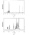
次に、YGAO11の吸収スペクトルおよび発光スペクトルを測定した。吸収スペクトルの測定は紫外可視分光光度計((株)日本分光製 V550型)を、発光スペクトルの測定は蛍光光度計((株)浜松ホトニクス製 FS920)を用いた。測定は、トルエン溶液および蒸着膜に関して室温で行った。トルエン溶液の測定結果を図7(a)に、蒸着膜の測定結果を図7(b)に、それぞれ示す。横軸は波長、縦軸は吸収および発光の強度を表す。 Next, the absorption spectrum and emission spectrum of YGAO11 were measured. The absorption spectrum was measured using an ultraviolet-visible spectrophotometer (model V550 manufactured by JASCO Corporation), and the emission spectrum was measured using a fluorometer (FS920 manufactured by Hamamatsu Photonics). The measurement was performed at room temperature for the toluene solution and the deposited film. FIG. 7A shows the measurement result of the toluene solution, and FIG. 7B shows the measurement result of the deposited film. The horizontal axis represents wavelength, and the vertical axis represents the intensity of absorption and emission.
図7(a)に示す通り、本発明のオキサジアゾール誘導体YGAO11はトルエン溶液中において、362nmに吸収ピークを有している。また、発光スペクトルは431nmにピークを有している。なお、発光スペクトルは、362nmの波長で励起することにより測定した。 As shown in FIG. 7A, the oxadiazole derivative YGAO11 of the present invention has an absorption peak at 362 nm in a toluene solution. The emission spectrum has a peak at 431 nm. The emission spectrum was measured by excitation at a wavelength of 362 nm.
また、図7(b)に示す通り、本発明のオキサジアゾール誘導体YGAO11の蒸着膜は、369nmに吸収ピークを有している。また、発光スペクトルは456nmにピークを有している。なお、発光スペクトルは、369nmの波長で励起することにより測定した。 Moreover, as shown in FIG.7 (b), the vapor deposition film of the oxadiazole derivative YGAO11 of this invention has an absorption peak at 369 nm. The emission spectrum has a peak at 456 nm. The emission spectrum was measured by excitation at a wavelength of 369 nm.
なお、図7(b)の吸収スペクトルのデータを用い、taucプロットにより吸収端を求め、その吸収端のエネルギーをエネルギーギャップとしてYGAO11のエネルギーギャップを求めたところ、3.06eVであった。このことから、本発明のオキサジアゾール誘導体YGAO11は、大きな励起エネルギーを有することがわかる。 In addition, using the data of the absorption spectrum of FIG.7 (b), when the absorption edge was calculated | required by tauc plot and the energy gap of YGAO11 was calculated | required by making the energy of the absorption edge into an energy gap, it was 3.06eV. This shows that the oxadiazole derivative YGAO11 of the present invention has a large excitation energy.
また、YGAO11の薄膜状態におけるイオン化ポテンシャルを大気中の光電子分光法(理研計器社製、AC−2)で測定した結果、5.49eVであった。その結果、HOMO準位が−5.49eVであることがわかった。さらに、上記で求めたエネルギーギャップの値とHOMO準位からLUMO準位を求めたところ、−2.43eVであった。 The ionization potential of YGAO11 in a thin film state was 5.49 eV as a result of measurement by atmospheric photoelectron spectroscopy (manufactured by Riken Keiki Co., Ltd., AC-2). As a result, it was found that the HOMO level was −5.49 eV. Further, when the LUMO level was determined from the energy gap value and the HOMO level determined above, it was -2.43 eV.
また、YGA011の基底状態における最適分子構造を、密度汎関数法(DFT)のB3LYP/6−311(d,p)により計算した。DFTは、電子相関を考慮しないハートリー・フォック(HF)法に比較して計算精度が良く、同レベルの計算精度である摂動法(MP)法よりも計算コストが小さいため、本計算で採用した。計算は、ハイパフォーマンスコンピュータ(HPC)(SGI社製、Altix3700 DX)を用いて行った。DFTで構造最適化した分子構造において時間依存密度汎関数法(TDDFT)のB3LYP/6−311(d,p)を適用することにより、YGA011の一重項励起エネルギー(エネルギーギャップ)を算出したところ、一重項励起エネルギーは3.18eVと算出された。また、YGAO11の三重項励起エネルギーを算出したところ、2.53eVと算出された。以上の結果から、本発明のオキサジアゾール誘導体は、励起エネルギーの大きい物質であることがわかる。特に、三重項励起エネルギーの大きい物質であることがわかる。 Moreover, the optimal molecular structure in the ground state of YGA011 was calculated by B3LYP / 6-311 (d, p) of density functional theory (DFT). DFT is used in this calculation because it has better calculation accuracy than the Hartree-Fock (HF) method, which does not take into account electronic correlation, and the calculation cost is lower than the perturbation method (MP) method, which is the same level of calculation accuracy. did. The calculation was performed using a high performance computer (HPC) (manufactured by SGI, Altix 3700 DX). By applying the time-dependent density functional theory (TDDFT) B3LYP / 6-311 (d, p) in the molecular structure optimized by DFT, the singlet excitation energy (energy gap) of YGA011 was calculated. Singlet excitation energy was calculated to be 3.18 eV. The triplet excitation energy of YGAO11 was calculated to be 2.53 eV. From the above results, it can be seen that the oxadiazole derivative of the present invention is a substance having a large excitation energy. In particular, it can be seen that the substance has a large triplet excitation energy.
また、示差走査熱量測定装置(DSC、パーキンエルマー社製、Pyris1)を用いてガラス転移点を測定した。まず、サンプルを40℃/minで330℃まで加熱した後、40℃/minで室温まで冷却した。その後10℃/minで330℃まで昇温し、40℃/minで室温まで冷却することにより、測定した。その結果、YGAO11のガラス転移点(Tg)は99℃であることがわかった。 Moreover, the glass transition point was measured using the differential scanning calorimeter (DSC, the Perkin Elmer company make, Pyris1). First, the sample was heated to 330 ° C. at 40 ° C./min, and then cooled to room temperature at 40 ° C./min. Thereafter, the temperature was raised to 330 ° C. at 10 ° C./min, and cooled to room temperature at 40 ° C./min, and then measured. As a result, it was found that the glass transition point (Tg) of YGAO11 was 99 ° C.
次に、YGAO11の酸化特性および還元特性を、サイクリックボルタンメトリ(CV)測定により調べた。測定装置は、電気化学アナライザー(ビー・エー・エス(株)製、型番:ALSモデル600A)を用いた。CV測定における溶液は、溶媒として脱水ジメチルホルムアミド(DMF)を用い、支持電解質である過塩素酸テトラ−n−ブチルアンモニウム(n−Bu4NClO4)を100mMの濃度となるように溶解させ、さらに測定対象であるYGAO11を1mMの濃度となるように溶解させて調製した。また、作用電極としては白金電極(ビー・エー・エス(株)製、PTE白金電極)を、補助電極としては白金電極(ビー・エー・エス(株)製、VC−3用Ptカウンター電極(5cm))を、基準電極としてはAg/Ag+電極(ビー・エー・エス(株)製、RE5非水溶媒系参照電極)をそれぞれ用いた。 Next, the oxidation characteristics and reduction characteristics of YGAO11 were examined by cyclic voltammetry (CV) measurement. As the measuring apparatus, an electrochemical analyzer (manufactured by BAS Co., Ltd., model number: ALS model 600A) was used. The solution in CV measurement uses dehydrated dimethylformamide (DMF) as a solvent, and dissolves the supporting electrolyte tetra-n-butylammonium perchlorate (n-Bu 4 NClO 4 ) to a concentration of 100 mM. YGAO11 which is a measurement object was prepared by dissolving to a concentration of 1 mM. In addition, as a working electrode, a platinum electrode (manufactured by BAS Co., Ltd., PTE platinum electrode), and as an auxiliary electrode, a platinum electrode (manufactured by BAS Inc., Pt counter electrode for VC-3 ( 5 cm)), and an Ag / Ag + electrode (manufactured by BAS Co., Ltd., RE5 nonaqueous solvent system reference electrode) was used as a reference electrode.
酸化特性については、まず基準電極に対する作用電極の電位を−0.11Vから0.90Vまでスキャンした後、続いて0.90Vから−0.11Vまでスキャンすることにより測定した。また、還元特性については、まず基準電極に対する作用電極の電位を−0.07から−2.60Vまでスキャンした後、続いて−2.60Vから−0.07Vまでスキャンすることにより測定した。なお、CV測定のスキャン速度は0.1V/sに設定した。 The oxidation characteristics were measured by first scanning the working electrode potential with respect to the reference electrode from −0.11 V to 0.90 V, and then scanning from 0.90 V to −0.11 V. The reduction characteristics were measured by first scanning the potential of the working electrode with respect to the reference electrode from −0.07 to −2.60 V, and then scanning from −2.60 V to −0.07 V. The scan speed for CV measurement was set to 0.1 V / s.
YGAO11の酸化特性について調べたCV曲線を図8(a)に、還元特性について調べたCV曲線を図8(b)に、それぞれ示す。図8において、横軸は基準電極に対する作用電極の電位を表し、縦軸は作用電極と補助電極との間に流れた電流値を表す。図8に示した通り、YGAO11は酸化ピークおよび還元ピークの両方が明確に観測された。具体的には、0.87V付近(vs.Ag/Ag+電極)に酸化を示す電流が観測され、−2.40V付近(vs.Ag/Ag+電極)に還元を示す電流が観測された。このことから、YGAO11は正孔も電子も入りやすい物質であることがわかった。 FIG. 8A shows a CV curve examined for the oxidation characteristics of YGAO11, and FIG. 8B shows a CV curve examined for the reduction characteristics. In FIG. 8, the horizontal axis represents the potential of the working electrode with respect to the reference electrode, and the vertical axis represents the value of current flowing between the working electrode and the auxiliary electrode. As shown in FIG. 8, in YGAO11, both an oxidation peak and a reduction peak were clearly observed. Specifically, a current indicating oxidation around 0.87V (vs.Ag/Ag + electrode) was observed, a current indicating reduction near -2.40V (vs.Ag/Ag + electrode) was observed . From this, it was found that YGAO11 is a substance that easily contains holes and electrons.
≪合成例2≫
本合成例2では、実施形態1の構造式(51)で表される本発明のオキサジアゾール誘導体、2−フェニル−5−{4−[N−フェニル−N−(9−フェニルカルバゾール−3−イル)アミノ]フェニル}−1,3,4−オキサジアゾール(略称:PCAO11)の合成例を具体的に例示する。
<< Synthesis Example 2 >>
In Synthesis Example 2, the oxadiazole derivative of the present invention represented by the structural formula (51) of
<ステップ1; 2−(4−ブロモフェニル)−5−フェニル−1,3,4−オキサジアゾール(略称:O11Br)の合成>
合成例1のステップ1において述べたので、ここでは省略する。
<
Since it was described in
<ステップ2; N−フェニル−(9−フェニルカルバゾール−3−イル)アミン(略称:PCA)の合成>
本ステップ2では、以下のような手順(i)〜(ii)に従って、PCAを合成した。
<
In
(i)3−ブロモ−9−フェニルカルバゾールの合成
まず、N−フェニルカルバゾール24.3g(100mmol)を氷酢酸600mLに溶かし、N−ブロモコハク酸イミド17.8g(100mmol)をゆっくり加え、室温で18時間撹拌した。この反応溶液を氷水1Lに撹拌しながら滴下し、析出した白色固体を水で3回洗浄した。得られた固体をジエチルエーテル150mLに溶解し、飽和炭酸水素ナトリウム水溶液、水で洗浄した。洗浄後、有機層を硫酸マグネシウムで乾燥させた。これを濾過し、ろ液を濃縮した後、得られた固体にメタノール約50mLを加え、超音波を照射して均一に溶解させた。この溶液を静置することで白色の析出物が得られた。これを濾過により回収し、乾燥させる事で、目的物である3−ブロモ−9−フェニルカルバゾールの白色粉末を28.4g得た(収率88%)。
(I) Synthesis of 3-bromo-9-phenylcarbazole First, 24.3 g (100 mmol) of N-phenylcarbazole was dissolved in 600 mL of glacial acetic acid, and 17.8 g (100 mmol) of N-bromosuccinimide was slowly added. Stir for hours. This reaction solution was added dropwise to 1 L of ice water with stirring, and the precipitated white solid was washed three times with water. The obtained solid was dissolved in 150 mL of diethyl ether and washed with a saturated aqueous sodium hydrogen carbonate solution and water. After washing, the organic layer was dried with magnesium sulfate. After filtering this and concentrating the filtrate, about 50 mL of methanol was added to the obtained solid, and it was uniformly dissolved by irradiation with ultrasonic waves. A white precipitate was obtained by allowing this solution to stand. This was recovered by filtration and dried to obtain 28.4 g of a white powder of 3-bromo-9-phenylcarbazole as a target product (yield 88%).
(ii)PCAの合成
次に、窒素下で、(i)で得た3−ブロモ−9−フェニルカルバゾール19g(60mmol)、ビス(ジベンジリデンアセトン)パラジウム(0)340mg(0.6mmol)、1,1−ビス(ジフェニルホスフィノ)フェロセン(略称:DPPF)1.6g(3.0mmol)、ナトリウムtert−ブトキシド13g(180mmol)の混合物に、脱水キシレン110mL、アニリン7.0g(75mmol)を加えた。これを窒素雰囲気下にて、90℃で7.5時間加熱撹拌した。反応終了後、得られた懸濁液に50℃に温めたトルエンを約500mL加え、フロリジール、アルミナ、セライトを通して濾過した。得られたろ液を濃縮し、析出した固体にヘキサンおよび酢酸エチルを加えて超音波を照射した。得られた懸濁液を濾過し、ろ物を乾燥することで、本ステップ2の目的物であるPCAのクリーム色粉末を15g得た(収率75%)。以上で述べた本ステップ2の合成スキームを下記スキーム(b−2)に示す。
(Ii) Synthesis of PCA Next, under nitrogen, 19 g (60 mmol) of 3-bromo-9-phenylcarbazole obtained in (i), 340 mg (0.6 mmol) of bis (dibenzylideneacetone) palladium (0), 1 , 1-bis (diphenylphosphino) ferrocene (abbreviation: DPPF) 1.6 g (3.0 mmol) and sodium tert-butoxide 13 g (180 mmol) were added to 110 mL of dehydrated xylene and 7.0 g (75 mmol) of aniline. . This was stirred with heating at 90 ° C. for 7.5 hours in a nitrogen atmosphere. After completion of the reaction, about 500 mL of toluene warmed to 50 ° C. was added to the obtained suspension, followed by filtration through Florisil, alumina, and celite. The obtained filtrate was concentrated, hexane and ethyl acetate were added to the precipitated solid, and ultrasonic waves were irradiated. The obtained suspension was filtered, and the filtrate was dried to obtain 15 g of PCA cream powder, which is the target product of
<ステップ3; 2−フェニル−5−{4−[N−フェニル−N−(9−フェニルカルバゾール−3−イル)アミノ]フェニル}−1,3,4−オキサジアゾール(略称:PCAO11)の合成>
ステップ1で得たO11Br1.0g(3.3mmol)、ステップ2で得たPCA1.1g(3.3mmol)、ナトリウムtert−ブトキシド0.6g(6.7mmol)を100mL三口フラスコに入れて窒素置換した後、トルエン15mL、トリtert−ブチルホスフィンの10%ヘキサン溶液0.1mLを加えてさらに窒素置換した。そこにビス(ジベンジリデンアセトン)パラジウム(0)0.1g(0.2mmol)を加え、80℃で5時間撹拌した。反応終了後、得られた固体をクロロホルムに溶解して水で洗浄し、セライトを通してろ過し、ろ液を水でさらに洗浄した。得られた有機層を硫酸マグネシウムにより乾燥した後、ろ過を行い、ろ液を濃縮した。得られた固体をトルエンに溶解し、シリカカラムクロマトグラフィーによる精製を行った。カラム精製はまずトルエンを展開溶媒として用い、次いでトルエン:酢酸エチル=1:1の混合溶媒を展開溶媒として用いることにより行った。クロロホルムとヘキサンで再結晶をしたところ、本合成例2の目的物であるPCAO11の黄色固体を0.99g得た(収率54%)。以上で述べた本ステップ3の合成スキームを下記スキーム(c−2)に示す。
<
O11Br (1.0 g, 3.3 mmol) obtained in
なお、上記ステップ3で得られたPCAO11の核磁気共鳴分光法(1H−NMR)による分析結果を下記に示す。また、1H−NMRチャートを図9(a)に、その拡大図を図9(b)に示す。このことから、本合成例2において、上述の構造式(51)で表される本発明のオキサジアゾール誘導体PCAO11が得られたことがわかった。
In addition, the analysis result by the nuclear magnetic resonance spectroscopy (< 1 > H-NMR) of PCAO11 obtained at the said
1H−NMR(CDCl3,300MHz):δ=7.11−7.65(m,20H),δ=7.93(d,J=9.0,2H),δ=8.03−7.98(m,2H),δ=8.12(m,2H) 1 H-NMR (CDCl 3 , 300 MHz): δ = 7.11-7.65 (m, 20H), δ = 7.93 (d, J = 9.0, 2H), δ = 8.03-7 .98 (m, 2H), δ = 8.12 (m, 2H)
また、得られたPCAO11の昇華精製をトレインサブリメーション法により行った。昇華精製は7Paの減圧下、アルゴンの流量を3mL/minとして270℃で12時間行った。PCAO11 0.99gに対し昇華精製を行ったところ、収量0.71gで収率は72%であった。 Further, sublimation purification of the obtained PCAO11 was performed by a train sublimation method. The sublimation purification was performed at 270 ° C. for 12 hours under a reduced pressure of 7 Pa with an argon flow rate of 3 mL / min. When sublimation purification was performed on 0.99 g of PCAO11, the yield was 0.71 g and the yield was 72%.
次に、PCAO11の吸収スペクトルおよび発光スペクトルを測定した。吸収スペクトルの測定は紫外可視分光光度計((株)日本分光製 V550型)を、発光スペクトルの測定は蛍光光度計((株)浜松ホトニクス製 FS920)を用いた。測定は、トルエン溶液および蒸着膜に関して室温で行った。トルエン溶液の測定結果を図10(a)に、蒸着膜の測定結果を図10(b)に、それぞれ示す。横軸は波長、縦軸は吸収および発光の強度を表す。 Next, the absorption spectrum and emission spectrum of PCAO11 were measured. The absorption spectrum was measured using an ultraviolet-visible spectrophotometer (model V550 manufactured by JASCO Corporation), and the emission spectrum was measured using a fluorometer (FS920 manufactured by Hamamatsu Photonics). The measurement was performed at room temperature for the toluene solution and the deposited film. The measurement result of the toluene solution is shown in FIG. 10 (a), and the measurement result of the deposited film is shown in FIG. 10 (b). The horizontal axis represents wavelength, and the vertical axis represents the intensity of absorption and emission.
図10(a)に示す通り、本発明のオキサジアゾール誘導体PCAO11はトルエン溶液中において、366nmに吸収ピークを有している。また、発光スペクトルは456nmにピークを有している。なお、発光スペクトルは、366nmの波長で励起することにより測定した。 As shown in FIG. 10A, the oxadiazole derivative PCAO11 of the present invention has an absorption peak at 366 nm in a toluene solution. The emission spectrum has a peak at 456 nm. The emission spectrum was measured by excitation at a wavelength of 366 nm.
また、図10(b)に示す通り、本発明のオキサジアゾール誘導体PCAO11の蒸着膜は、377nmに吸収ピークを有している。また、発光スペクトルは483nmにピークを有している。なお、発光スペクトルは、356nmの波長で励起することにより測定した。 Further, as shown in FIG. 10B, the deposited film of the oxadiazole derivative PCAO11 of the present invention has an absorption peak at 377 nm. The emission spectrum has a peak at 483 nm. The emission spectrum was measured by excitation with a wavelength of 356 nm.
なお、図10(b)の吸収スペクトルのデータを用い、taucプロットにより吸収端を求め、その吸収端のエネルギーをエネルギーギャップとしてPCAO11のエネルギーギャップを求めたところ、2.97eVであった。このことから、本発明のオキサジアゾール誘導体PCAO11は、大きな励起エネルギーを有することがわかる。 In addition, it was 2.97 eV when the absorption gap was calculated | required using the data of the absorption spectrum of FIG.10 (b), the absorption edge was calculated | required by tauc plot, and the energy of the absorption edge was made into the energy gap. This shows that the oxadiazole derivative PCAO11 of the present invention has a large excitation energy.
また、PCAO11の薄膜状態におけるイオン化ポテンシャルを大気中の光電子分光法(理研計器社製、AC−2)で測定した結果、5.30eVであった。その結果、HOMO準位が−5.30eVであることがわかった。さらに、上記で求めたエネルギーギャップの値とHOMO準位からLUMO準位を求めたところ、−2.33eVであった。 The ionization potential of PCAO11 in a thin film state was 5.30 eV as a result of measurement by atmospheric photoelectron spectroscopy (AC-2, manufactured by Riken Keiki Co., Ltd.). As a result, it was found that the HOMO level was −5.30 eV. Further, when the LUMO level was determined from the energy gap value and the HOMO level determined above, it was -2.33 eV.
また、PCA011の基底状態における最適分子構造を、密度汎関数法(DFT)のB3LYP/6−311(d,p)により計算した。DFTは、電子相関を考慮しないハートリー・フォック(HF)法に比較して計算精度が良く、同レベルの計算精度である摂動法(MP)法よりも計算コストが小さいため、本計算で採用した。計算は、ハイパフォーマンスコンピュータ(HPC)(SGI社製、Altix3700 DX)を用いて行った。DFTで構造最適化した分子構造において時間依存密度汎関数法(TDDFT)のB3LYP/6−311(d,p)を適用することにより、PCA011の一重項励起エネルギー(エネルギーギャップ)を算出したところ、一重項励起エネルギーは3.11eVと算出された。また、PCAO11の三重項励起エネルギーを算出したところ、2.50eVと算出された。以上の結果から、本発明のオキサジアゾール誘導体は、励起エネルギーの大きい物質であることがわかる。特に、三重項励起エネルギーの大きい物質であることがわかる。 Moreover, the optimal molecular structure in the ground state of PCA011 was calculated by B3LYP / 6-311 (d, p) of density functional theory (DFT). DFT is used in this calculation because it has better calculation accuracy than the Hartree-Fock (HF) method, which does not take into account electronic correlation, and the calculation cost is lower than the perturbation method (MP) method, which is the same level of calculation accuracy. did. The calculation was performed using a high performance computer (HPC) (manufactured by SGI, Altix 3700 DX). By applying the time-dependent density functional theory (TDDFT) B3LYP / 6-311 (d, p) in the molecular structure optimized by DFT, the singlet excitation energy (energy gap) of PCA011 was calculated. Singlet excitation energy was calculated to be 3.11 eV. The triplet excitation energy of PCAO11 was calculated to be 2.50 eV. From the above results, it can be seen that the oxadiazole derivative of the present invention is a substance having a large excitation energy. In particular, it can be seen that the substance has a large triplet excitation energy.
また、示差走査熱量測定装置(DSC、パーキンエルマー社製、Pyris1)を用いてガラス転移点を測定した。まず、サンプルを40℃/minで280℃まで加熱した後、40℃/minで室温まで冷却した。その後10℃/minで280℃まで昇温し、40℃/minで室温まで冷却することにより、測定した。その結果、PCAO11のガラス転移点(Tg)は103℃であることがわかった。 Moreover, the glass transition point was measured using the differential scanning calorimeter (DSC, the Perkin Elmer company make, Pyris1). First, the sample was heated to 280 ° C. at 40 ° C./min, and then cooled to room temperature at 40 ° C./min. Thereafter, the temperature was increased to 280 ° C. at 10 ° C./min and cooled to room temperature at 40 ° C./min. As a result, it was found that the glass transition point (Tg) of PCAO11 was 103 ° C.
次に、PCAO11の酸化特性および還元特性を、サイクリックボルタンメトリ(CV)測定により調べた。測定装置およびCV測定用の溶液濃度は、先の合成例1と同様とした。 Next, the oxidation characteristic and reduction characteristic of PCAO11 were examined by cyclic voltammetry (CV) measurement. The measurement apparatus and the solution concentration for CV measurement were the same as those in Synthesis Example 1 above.
酸化特性については、まず基準電極に対する作用電極の電位を−0.22Vから0.80Vまでスキャンした後、続いて0.80Vから−0.22Vまでスキャンすることにより測定した。また、還元特性については、まず基準電極に対する作用電極の電位を−0.60Vから−2.70Vまでスキャンした後、続いて−2.70Vから−0.60Vまでスキャンすることにより測定した。なお、CV測定のスキャン速度は0.1V/sに設定した。 The oxidation characteristic was measured by first scanning the potential of the working electrode with respect to the reference electrode from −0.22 V to 0.80 V, and then scanning from 0.80 V to −0.22 V. The reduction characteristics were measured by first scanning the potential of the working electrode with respect to the reference electrode from −0.60 V to −2.70 V, and then scanning from −2.70 V to −0.60 V. The scan speed for CV measurement was set to 0.1 V / s.
PCAO11の酸化特性について調べたCV曲線を図11(a)に、還元特性について調べたCV曲線を図11(b)に、それぞれ示す。図11において、横軸は基準電極に対する作用電極の電位を表し、縦軸は作用電極と補助電極との間に流れた電流値を表す。図11に示した通り、PCAO11は酸化ピークおよび還元ピークの両方が明確に観測された。このことから、PCAO11は正孔も電子も入りやすい物質であることがわかった。 FIG. 11 (a) shows the CV curve examined for the oxidation characteristics of PCAO11, and FIG. 11 (b) shows the CV curve examined for the reduction characteristics. In FIG. 11, the horizontal axis represents the potential of the working electrode with respect to the reference electrode, and the vertical axis represents the current value flowing between the working electrode and the auxiliary electrode. As shown in FIG. 11, both an oxidation peak and a reduction peak were clearly observed in PCAO11. From this, it was found that PCAO11 is a substance that easily contains holes and electrons.
≪合成例3≫
本合成例3では、実施形態1の構造式(91)で表される本発明のオキサジアゾール誘導体、2−{4−[N−(4−ジフェニルアミノフェニル)−N−フェニルアミノ]フェニル}−5−フェニル−1,3,4−オキサジアゾール(略称:DPAO11)の合成例を具体的に例示する。
<< Synthesis Example 3 >>
In Synthesis Example 3, the oxadiazole derivative of the present invention represented by the structural formula (91) of
<ステップ1; 2−(4−ブロモフェニル)−5−フェニル−1,3,4−オキサジアゾール(略称:O11Br)の合成>
合成例1のステップ1において述べたので、ここでは省略する。
<
Since it was described in
<ステップ2; N,N,N’−トリフェニル−1,4−フェニレンジアミン(略称:DPA)の合成>
本ステップ2では、以下のような手順(i)〜(ii)に従って、DPAを合成した。
<Step 2: Synthesis of N, N, N′-triphenyl-1,4-phenylenediamine (abbreviation: DPA)>
In
(i)4−ブロモトリフェニルアミンの合成
まず、1000mLエーレンマイヤーフラスコにトリフェニルアミン25g(100mmol)、N−ブロモスクシンイミド18g(100mmol)、酢酸エチル400mLを入れ、空気中室温で18時間攪拌した。反応終了後、飽和炭酸ナトリウム水溶液で2回洗浄し、有機層と水層を得た。水層を酢酸エチルで2回抽出した後、その抽出物を有機層とあわせ、飽和食塩水で洗浄した。硫酸マグネシウムにより乾燥後、自然ろ過してろ液を濃縮し、得られた無色固体を酢酸エチル−ヘキサンにより再結晶したところ、目的物である4−ブロモトリフェニルアミンの無色粉末状固体を22g得た(収率66%)。
(I) Synthesis of 4-bromotriphenylamine First, 25 g (100 mmol) of triphenylamine, 18 g (100 mmol) of N-bromosuccinimide and 400 mL of ethyl acetate were placed in a 1000 mL Erlenmeyer flask and stirred at room temperature in air for 18 hours. After completion of the reaction, the organic layer and aqueous layer were obtained by washing twice with a saturated aqueous sodium carbonate solution. The aqueous layer was extracted twice with ethyl acetate, and the extract was combined with the organic layer and washed with saturated brine. After drying with magnesium sulfate, the solution was naturally filtered and the filtrate was concentrated. The obtained colorless solid was recrystallized with ethyl acetate-hexane to obtain 22 g of a colorless powdery solid of 4-bromotriphenylamine as the target product. (Yield 66%).
(ii)N,N,N’−トリフェニル−1,4−フェニレンジアミン(略称:DPA)の合成
上記(i)で得た4−ブロモトリフェニルアミン0.56g(6mmol)、ビス(ジベンジリデンアセトン)パラジウム(0)0.35g(0.6mmol)、ナトリウム tert−ブトキシド0.58g(6mmol)を100mL三口フラスコへ入れ、トルエン5mLを加えて窒素置換した後、アニリン0.56g(6mmol)、トリtert−ブチルホスフィンの10%ヘキサン溶液0.37mL(1.8mmol)を加え、80℃で5時間加熱撹拌を行った。反応後、飽和食塩水を加えて反応を終了させ、水層を酢酸エチル約100mLで抽出した。抽出物を硫酸マグネシウムにより乾燥後、ろ過した。ろ液を濃縮した後、酢酸エチル:ヘキサン=1:20のシリカゲルカラムにて精製を行ったところ、本ステップ2の目的物であるDPAの淡黄色粉末状固体0.24gを得た(収率42%)。以上で述べた本ステップ2の合成スキームを下記スキーム(b−3)に示す。
(Ii) Synthesis of N, N, N′-triphenyl-1,4-phenylenediamine (abbreviation: DPA) 0.56 g (6 mmol) of 4-bromotriphenylamine obtained in (i) above, bis (dibenzylidene) Acetone) palladium (0) 0.35 g (0.6 mmol), sodium tert-butoxide 0.58 g (6 mmol) was placed in a 100 mL three-necked flask, and 5 mL of toluene was added and the atmosphere was replaced with nitrogen. Then, aniline 0.56 g (6 mmol), 0.37 mL (1.8 mmol) of a 10% hexane solution of tritert-butylphosphine was added, and the mixture was heated and stirred at 80 ° C. for 5 hours. After the reaction, saturated brine was added to terminate the reaction, and the aqueous layer was extracted with about 100 mL of ethyl acetate. The extract was dried over magnesium sulfate and filtered. The filtrate was concentrated and purified on a silica gel column of ethyl acetate: hexane = 1: 20 to obtain 0.24 g of a light yellow powdery solid of DPA which is the target product of Step 2 (yield). 42%). The synthesis scheme of
<ステップ3; 2−{4−[N−(4−ジフェニルアミノフェニル)−N−フェニルアミノ]フェニル}−5−フェニル−1,3,4−オキサジアゾール(略称:DPAO11)の合成>
ステップ1で得たO11Br0.61g(2.0mmol)、ステップ2で示した方法により得られたDPA0.67g(2.0mmol)、ナトリウムtert−ブトキシド1.0g(10.4mmol)、ビス(ジベンジリデンアセトン)パラジウム(0)0.014g(0.02mmol)を50mL三口フラスコに入れて窒素置換し、トルエン7mL、トリtert−ブチルホスフィンの10%ヘキサン溶液0.1mLを加え、80℃で8時間加熱撹拌した。反応終了後、得られた固体をクロロホルムに溶解し、水、飽和食塩水の順に洗浄した後、セライトを通してろ過した。ろ液を濃縮し、得られた固体をトルエンに溶解し、シリカカラムクロマトグラフィーによる精製を行った。カラム精製はまずトルエンを展開溶媒として用い、次いでトルエン:酢酸エチル=1:1の混合溶媒を展開溶媒として用いることにより行った。クロロホルムとヘキサンで再結晶をしたところ、本合成例3の目的物であるDPAO11の黄色固体を0.65g得た(収率58%)。以上で述べた本ステップ3の合成スキームを下記(c−3)に示す。
<
0.61 g (2.0 mmol) of O11Br obtained in
なお、上記ステップ3で得られたDPAO11の核磁気共鳴分光法(1H−NMR)による分析結果を下記に示す。また、1H−NMRチャートを図12(a)に、その拡大図を図12(b)に示す。このことから、本合成例3において、上述の構造式(91)で表される本発明のオキサジアゾール誘導体DPAO11が得られたことがわかった。
In addition, the analysis result by the nuclear magnetic resonance spectroscopy (< 1 > H-NMR) of DPAO11 obtained at the said
1H−NMR(CDCl3,300MHz):δ=7.00−7.37(m,21H),δ=7.52(m,3H),δ=7.95(d,J=9.0,2H),δ=8.10−8.13(m,2H) 1 H-NMR (CDCl 3 , 300 MHz): δ = 7.00-7.37 (m, 21H), δ = 7.52 (m, 3H), δ = 7.95 (d, J = 9.0) , 2H), δ = 8.10-8.13 (m, 2H)
次に、DPAO11の吸収スペクトルおよび発光スペクトルを測定した。吸収スペクトルの測定は紫外可視分光光度計((株)日本分光製 V550型)を、発光スペクトルの測定は蛍光光度計((株)浜松ホトニクス製 FS920)を用いた。測定は、トルエン溶液および蒸着膜に関して室温で行った。トルエン溶液の測定結果を図13(a)に、蒸着膜の測定結果を図13(b)に、それぞれ示す。横軸は波長、縦軸は吸収および発光の強度を表す。 Next, the absorption spectrum and emission spectrum of DPAO11 were measured. The absorption spectrum was measured using an ultraviolet-visible spectrophotometer (model V550 manufactured by JASCO Corporation), and the emission spectrum was measured using a fluorometer (FS920 manufactured by Hamamatsu Photonics). The measurement was performed at room temperature for the toluene solution and the deposited film. FIG. 13A shows the measurement result of the toluene solution, and FIG. 13B shows the measurement result of the deposited film. The horizontal axis represents wavelength, and the vertical axis represents the intensity of absorption and emission.
図13(a)に示す通り、本発明のオキサジアゾール誘導体DPAO11はトルエン溶液中において、369nmに吸収ピークを有している。また、発光スペクトルは498nmにピークを有している。なお、発光スペクトルは、369nmの波長で励起することにより測定した。 As shown in FIG. 13 (a), the oxadiazole derivative DPAO11 of the present invention has an absorption peak at 369 nm in a toluene solution. The emission spectrum has a peak at 498 nm. The emission spectrum was measured by excitation at a wavelength of 369 nm.
また、図13(b)に示す通り、本発明のオキサジアゾール誘導体DPAO11の蒸着膜は、373nmに吸収ピークを有している。また、発光スペクトルは504nmにピークを有している。なお、発光スペクトルは、373nmの波長で励起することにより測定した。 Moreover, as shown in FIG.13 (b), the vapor deposition film | membrane of the oxadiazole derivative DPAO11 of this invention has an absorption peak at 373 nm. The emission spectrum has a peak at 504 nm. The emission spectrum was measured by excitation at a wavelength of 373 nm.
なお、図13(b)の吸収スペクトルのデータを用い、taucプロットにより吸収端を求め、その吸収端のエネルギーをエネルギーギャップとしてDPAO11のエネルギーギャップを求めたところ、2.99eVであった。このことから、本発明のオキサジアゾール誘導体DPAO11は、大きな励起エネルギーを有することがわかる。 In addition, using the data of the absorption spectrum of FIG. 13B, the absorption edge was obtained by tauc plot, and the energy gap of DPAO11 was obtained by using the energy at the absorption edge as the energy gap, which was 2.99 eV. This shows that the oxadiazole derivative DPAO11 of the present invention has a large excitation energy.
また、DPAO11の薄膜状態におけるイオン化ポテンシャルを大気中の光電子分光法(理研計器社製、AC−2)で測定した結果、5.41eVであった。その結果、HOMO準位が−5.41eVであることがわかった。さらに、上記で求めたエネルギーギャップの値とHOMO準位からLUMO準位を求めたところ、−2.42eVであった。 Further, the ionization potential of DPAO11 in a thin film state was measured by photoelectron spectroscopy in the atmosphere (manufactured by Riken Keiki Co., Ltd., AC-2), and found to be 5.41 eV. As a result, it was found that the HOMO level was −5.41 eV. Furthermore, when the LUMO level was determined from the energy gap value determined above and the HOMO level, it was -2.42 eV.
また、示差走査熱量測定装置(DSC、パーキンエルマー社製、Pyris1)を用いてガラス転移点を測定した。まず、サンプルを40℃/minで280℃まで加熱した後、40℃/minで室温まで冷却した。その後10℃/minで280℃まで昇温し、40℃/minで室温まで冷却することにより、測定した。その結果、DPAO11のガラス転移点(Tg)は72℃であることがわかった。 Moreover, the glass transition point was measured using the differential scanning calorimeter (DSC, the Perkin Elmer company make, Pyris1). First, the sample was heated to 280 ° C. at 40 ° C./min, and then cooled to room temperature at 40 ° C./min. Thereafter, the temperature was increased to 280 ° C. at 10 ° C./min and cooled to room temperature at 40 ° C./min. As a result, it was found that the glass transition point (Tg) of DPAO11 was 72 ° C.
次に、DPAO11の酸化特性および還元特性を、サイクリックボルタンメトリ(CV)測定により調べた。測定装置およびCV測定用の溶液濃度は、先の合成例1と同様とした。 Next, the oxidation characteristics and reduction characteristics of DPAO11 were examined by cyclic voltammetry (CV) measurement. The measurement apparatus and the solution concentration for CV measurement were the same as those in Synthesis Example 1 above.
酸化特性については、まず基準電極に対する作用電極の電位を−0.35Vから0.60Vまでスキャンした後、続いて0.60Vから−0.35Vまでスキャンすることにより測定した。また、還元特性については、まず基準電極に対する作用電極の電位を−0.32Vから−2.60Vまでスキャンした後、続いて−2.60Vから−0.32Vまでスキャンすることにより測定した。なお、CV測定のスキャン速度は0.1V/sに設定した。 The oxidation characteristic was measured by first scanning the potential of the working electrode with respect to the reference electrode from −0.35 V to 0.60 V, and then scanning from 0.60 V to −0.35 V. The reduction characteristic was measured by first scanning the potential of the working electrode with respect to the reference electrode from −0.32 V to −2.60 V, and then scanning from −2.60 V to −0.32 V. The scan speed for CV measurement was set to 0.1 V / s.
DPAO11の酸化特性について調べたCV曲線を図14(a)に、還元特性について調べたCV曲線を図14(b)に、それぞれ示す。図14において、横軸は基準電極に対する作用電極の電位を表し、縦軸は作用電極と補助電極との間に流れた電流値を表す。図14に示した通り、DPAO11は酸化ピークおよび還元ピークの両方が明確に観測された。このことから、DPAO11は正孔も電子も入りやすい物質であることがわかった。 FIG. 14A shows a CV curve examined for the oxidation characteristics of DPAO11, and FIG. 14B shows a CV curve examined for the reduction characteristics. In FIG. 14, the horizontal axis represents the potential of the working electrode with respect to the reference electrode, and the vertical axis represents the current value flowing between the working electrode and the auxiliary electrode. As shown in FIG. 14, both oxidation peak and reduction peak were clearly observed in DPAO11. From this, it was found that DPAO11 is a substance in which holes and electrons can easily enter.
本実施例2では、実施例1の合成例1にて合成した本発明のオキサジアゾール誘導体YGAO11を発光層のホスト材料として用い、緑色発光の燐光性化合物をゲスト材料として用いた発光素子の例を具体的に例示する。素子構造を図1に示す。 In Example 2, an example of a light-emitting element using the oxadiazole derivative YGAO11 of the present invention synthesized in Synthesis Example 1 of Example 1 as a host material of a light-emitting layer and a green-emitting phosphorescent compound as a guest material Is specifically exemplified. The element structure is shown in FIG.
≪本実施例2の発光素子の作製≫
まず、110nmの膜厚で酸化珪素を含むインジウム錫酸化物(ITSO)が成膜されたガラス基板を用意する。ITSO表面は、2mm角の大きさで表面が露出するよう周辺を絶縁膜で覆った。なお、ITSOは発光素子の陽極として機能する第1の電極101である。この基板上に発光素子を形成するための前処理として、多孔質樹脂のブラシを用いて基板表面を洗浄し、200℃で1時間焼成した後、UVオゾン処理を370秒行った。
<< Production of Light-Emitting Element of Example 2 >>
First, a glass substrate on which indium tin oxide containing silicon oxide (ITSO) is formed to a thickness of 110 nm is prepared. The ITSO surface was covered with an insulating film so that the surface was exposed with a size of 2 mm square. Note that ITSO is the
次に、ITSOが形成された面が下方となるように、基板を真空蒸着装置内に設けられたホルダーに固定した。 Next, the substrate was fixed to a holder provided in the vacuum deposition apparatus so that the surface on which ITSO was formed faced down.
真空装置内を10−4Paに減圧した後、下記構造式(i)で表されるNPBと酸化モリブデン(VI)とを、NPB:酸化モリブデン(VI)=4:1(質量比)となるように共蒸着することにより、正孔注入層111を形成した。膜厚は50nmとした。なお、共蒸着とは、異なる複数の物質をそれぞれ異なる蒸発源から同時に蒸発させる蒸着法である。次に、NPBを10nm蒸着することにより、正孔輸送層112を形成した。さらに正孔輸送層112上に、本発明のオキサジアゾール誘導体YGAO11と下記構造式(ii)で表されるIr(ppy)2(acac)とを、YGAO11:Ir(ppy)2(acac)=1:0.08(質量比)となるように共蒸着することにより、発光層113を形成した。膜厚は30nmとした。次に、下記構造式(iii)で表されるBCPを10nm蒸着することにより、電子輸送層114を形成した。さらに電子輸送層114上に、下記構造式(iv)で表されるAlq3とリチウム(Li)とを、Alq3:Li=1:0.01(質量比)となるように共蒸着することにより、電子注入層115を形成した。膜厚は30nmとした。最後に、陰極として機能する第2の電極102としてアルミニウムを200nm成膜し、本発明の発光素子を得た。なお、上述した蒸着過程において、蒸着は全て抵抗加熱法を用いた。
After reducing the pressure in the vacuum apparatus to 10 −4 Pa, NPB represented by the following structural formula (i) and molybdenum oxide (VI) are NPB: molybdenum oxide (VI) = 4: 1 (mass ratio). Thus, the
≪比較例1の発光素子の作製≫
比較のため、本発明のオキサジアゾール誘導体YGAO11に換えて、下記構造式(v)で表されるCBPを用いた以外は上記実施例2と同様にして、比較例1の発光素子を作製した。すなわち比較例1の発光素子の発光層113は、CBP:Ir(ppy)2(acac)=1:0.08(質量比)となるように共蒸着することにより形成した。なお、CBPは燐光性化合物のホスト材料として、広く用いられている既知化合物である。
<< Production of Light-Emitting Element of Comparative Example 1 >>
For comparison, a light emitting device of Comparative Example 1 was fabricated in the same manner as in Example 2 except that CBP represented by the following structural formula (v) was used instead of the oxadiazole derivative YGAO11 of the present invention. . That is, the light-emitting
≪実施例2および比較例1の発光素子の動作特性≫
以上により得られた実施例2および比較例1の発光素子を、窒素雰囲気のグローブボックス内において、発光素子が大気に曝されないように封止する作業を行った後、これらの発光素子の動作特性について測定を行った。なお、測定は室温(25℃に保たれた雰囲気)で行った。
<< Operation Characteristics of Light-Emitting Elements of Example 2 and Comparative Example 1 >>
After performing the operation | work which seals the light emitting element of Example 2 and the comparative example 1 which were obtained by the above in the glove box of nitrogen atmosphere so that a light emitting element might not be exposed to air | atmosphere, the operating characteristic of these light emitting elements Was measured. The measurement was performed at room temperature (atmosphere kept at 25 ° C.).
実施例2および比較例1の発光素子の電流密度−輝度特性を図15(a)に、電圧−輝度特性を図15(b)に、それぞれ示す。図15から、電流密度−輝度特性は同等であるが、電圧−輝度特性は実施例2の方が優れていることがわかる。例えば、4.0Vの電圧印加時において比較すると、本実施例2の発光素子は4.76mA/cm2の電流密度で電流が流れ、2080cd/m2の輝度で発光したのに対し、比較例1の発光素子は1.16mA/cm2の電流密度でしか電流が流れず、発光輝度も568cd/m2であった。したがって、本実施例2の発光素子は、比較例1の発光素子よりも駆動電圧が低いことがわかった。図16は実施例2および比較例1の発光素子の電圧−電流密度特性であるが、この図から、本発明のオキサジアゾール誘導体はCBPに比べて電流を流しやすいことがわかる。そして、このことが駆動電圧の低減に繋がったと考えられる。また、実施例2および比較例1の発光素子に1mAの電流を流したときの発光スペクトルを図28に示す。4.0Vの電圧を印加した際、実施例2の発光素子のCIE色度座標は(x,y)=(0.32,0.65)であり、比較例1の発光素子のCIE色度座標は(x,y)=(0.33,0.64)であり、いずれもゲスト材料であるIr(ppy)2(acac)からの緑色発光が得られていた。 FIG. 15A shows the current density-luminance characteristics and FIG. 15B shows the voltage-luminance characteristics of the light-emitting elements of Example 2 and Comparative Example 1, respectively. FIG. 15 shows that the current density-luminance characteristics are the same, but the voltage-luminance characteristics are better in Example 2. For example, when compared with a voltage of 4.0 V, the light-emitting element of Example 2 flows with a current density of 4.76 mA / cm 2 and emits light with a luminance of 2080 cd / m 2. In the light-emitting element No. 1, current flowed only at a current density of 1.16 mA / cm 2 , and the light emission luminance was 568 cd / m 2 . Therefore, it was found that the driving voltage of the light emitting element of Example 2 was lower than that of the light emitting element of Comparative Example 1. FIG. 16 shows voltage-current density characteristics of the light-emitting elements of Example 2 and Comparative Example 1. From this graph, it can be seen that the oxadiazole derivative of the present invention is more likely to pass current than CBP. This is thought to have led to a reduction in drive voltage. 28 shows emission spectra when a current of 1 mA is passed through the light-emitting elements of Example 2 and Comparative Example 1. FIG. When a voltage of 4.0 V was applied, the CIE chromaticity coordinates of the light emitting device of Example 2 were (x, y) = (0.32, 0.65), and the CIE chromaticity of the light emitting device of Comparative Example 1 The coordinates were (x, y) = (0.33, 0.64), and in all cases, green light emission from Ir (ppy) 2 (acac) which is a guest material was obtained.
また、これらの発光素子の輝度−電流効率特性を図17(a)に示す。図17(b)は、図17(a)の縦軸を外部量子効率に換算したものである。図17から、本実施例2の発光素子は、1000cd/m2のとき、40cd/Aを超える高い電流効率を示していることがわかる。また、本実施例2の発光素子の1000cd/m2のときの外部量子収率は12%であった。また、本実施例2の発光素子の1000cd/m2のときのパワー効率を求めたところ、39lm/Wであり、高いパワー効率を示した。 In addition, FIG. 17A shows luminance-current efficiency characteristics of these light-emitting elements. FIG. 17B is a graph in which the vertical axis of FIG. 17A is converted to external quantum efficiency. FIG. 17 indicates that the light-emitting element of Example 2 exhibits high current efficiency exceeding 40 cd / A at 1000 cd / m 2 . In addition, the external quantum yield of the light-emitting element of Example 2 at 1000 cd / m 2 was 12%. Further, when the power efficiency of the light-emitting element of Example 2 at 1000 cd / m 2 was obtained, it was 39 lm / W, which showed high power efficiency.
以上のことから、本発明のオキサジアゾール誘導体を発光層のホスト材料として用い、燐光性化合物をゲスト材料として用いて発光素子を作製することにより、高い発光効率が得られる上に、駆動電圧を低減できることがわかった。したがって、本発明を実施することにより、消費電力の少ない発光素子が得られることがわかった。 As described above, by using the oxadiazole derivative of the present invention as a host material for a light-emitting layer and using a phosphorescent compound as a guest material to produce a light-emitting element, high luminous efficiency can be obtained and a driving voltage can be set. It was found that it can be reduced. Therefore, it was found that by implementing the present invention, a light-emitting element with low power consumption can be obtained.
本実施例3では、実施例1の合成例1にて合成した本発明のオキサジアゾール誘導体YGAO11を発光層のホスト材料として用い、赤色発光の燐光性化合物をゲスト材料として用いた発光素子の例を具体的に例示する。素子構造を図1に示す。 In this Example 3, an example of a light-emitting element using the oxadiazole derivative YGAO11 of the present invention synthesized in Synthesis Example 1 of Example 1 as a host material of a light-emitting layer and using a phosphorescent compound emitting red light as a guest material. Is specifically exemplified. The element structure is shown in FIG.
まず、110nmの膜厚で酸化珪素を含むインジウム錫酸化物(ITSO)が成膜されたガラス基板を用意する。ITSO表面は、2mm角の大きさで表面が露出するよう周辺を絶縁膜で覆った。なお、ITSOは発光素子の陽極として機能する第1の電極101である。この基板上に発光素子を形成するための前処理として、多孔質樹脂のブラシを用いて基板表面を洗浄し、200℃で1時間焼成した後、UVオゾン処理を370秒行った。
First, a glass substrate on which indium tin oxide containing silicon oxide (ITSO) is formed to a thickness of 110 nm is prepared. The ITSO surface was covered with an insulating film so that the surface was exposed with a size of 2 mm square. Note that ITSO is the
次に、ITSOが形成された面が下方となるように、基板を真空蒸着装置内に設けられたホルダーに固定した。 Next, the substrate was fixed to a holder provided in the vacuum deposition apparatus so that the surface on which ITSO was formed faced down.
真空装置内を10−4Paに減圧した後、NPBと酸化モリブデン(VI)とを、NPB:酸化モリブデン(VI)=4:1(質量比)となるように共蒸着することにより、正孔注入層111を形成した。膜厚は50nmとした。次に、NPBを10nm蒸着することにより、正孔輸送層112を形成した。さらに正孔輸送層112上に、本発明のオキサジアゾール誘導体YGAO11と下記構造式(vi)で表されるIr(Fdpq)2(acac)とを、YGAO11:Ir(Fdpq)2(acac)=1:0.05(質量比)となるように共蒸着することにより、発光層113を形成した。膜厚は30nmとした。次に、下記構造式(vii)で表されるBAlqを10nm蒸着することにより、電子輸送層114を形成した。さらに電子輸送層114上に、Alq3とリチウム(Li)とを、Alq3:Li=1:0.01(質量比)となるように共蒸着することにより、電子注入層115を形成した。膜厚は50nmとした。最後に、陰極として機能する第2の電極102としてアルミニウムを200nm成膜し、本発明の発光素子を得た。なお、上述した蒸着過程において、蒸着は全て抵抗加熱法を用いた。
After depressurizing the inside of the vacuum apparatus to 10 −4 Pa, NPB and molybdenum oxide (VI) are co-evaporated so that NPB: molybdenum oxide (VI) = 4: 1 (mass ratio), thereby forming holes. An
この発光素子を、窒素雰囲気のグローブボックス内において、発光素子が大気に曝されないように封止する作業を行った後、発光素子の動作特性について測定した。なお、測定は室温(25℃に保たれた雰囲気)で行った。 The light-emitting element was sealed in a glove box in a nitrogen atmosphere so that the light-emitting element was not exposed to the atmosphere, and then the operating characteristics of the light-emitting element were measured. The measurement was performed at room temperature (atmosphere kept at 25 ° C.).
この発光素子の電流密度−輝度特性を図18(a)に、電圧−輝度特性を図18(b)に、それぞれ示す。本実施例3の発光素子は、5.8Vの電圧を印加することにより18.0mA/cm2の電流密度で電流が流れ、1020cd/m2の輝度で発光した。このことから、本発明の発光素子は、低い電圧で動作することがわかった。なお、5.8Vの電圧を印加した際、本実施例3の発光素子のCIE色度座標は(x,y)=(0.71,0.29)であり、ゲスト材料であるIr(Fdpq)2(acac)からの深赤色発光が得られていた。 FIG. 18A shows the current density-luminance characteristics and FIG. 18B shows the voltage-luminance characteristics of this light-emitting element. In the light-emitting element of Example 3, when a voltage of 5.8 V was applied, a current flowed at a current density of 18.0 mA / cm 2 , and light was emitted with a luminance of 1020 cd / m 2 . From this, it was found that the light-emitting element of the present invention operates at a low voltage. Note that when a voltage of 5.8 V was applied, the CIE chromaticity coordinates of the light emitting element of Example 3 were (x, y) = (0.71, 0.29), and Ir (Fdpq) which is a guest material 2 ) Deep red light emission from 2 (acac) was obtained.
また、この発光素子の輝度−電流効率特性を図19(a)に示す。図19(b)は、図19(a)の縦軸を外部量子効率に換算したものである。図19からわかる通り、本実施例3の発光素子は、視感度の低い深赤色発光であるにもかかわらず、発光効率の最大値は6.63cd/Aであり、非常に高い発光効率を示した。また、その時の外部量子効率は13.9%であった。 In addition, FIG. 19A shows luminance-current efficiency characteristics of the light-emitting element. FIG. 19B is a graph in which the vertical axis of FIG. 19A is converted to external quantum efficiency. As can be seen from FIG. 19, the light-emitting element of Example 3 has a maximum luminous efficiency of 6.63 cd / A despite the fact that it emits deep red light with low visibility, and exhibits a very high luminous efficiency. It was. The external quantum efficiency at that time was 13.9%.
以上のことから、本発明のオキサジアゾール誘導体を発光層のホスト材料として用い、燐光性化合物をゲスト材料として用いて発光素子を作製することにより、発光効率が高く、かつ駆動電圧の低い発光素子が得られることがわかった。したがって、本発明を実施することにより、消費電力の少ない発光素子が得られることがわかった。 As described above, a light-emitting element with high emission efficiency and low driving voltage can be manufactured by using the oxadiazole derivative of the present invention as a host material for a light-emitting layer and using a phosphorescent compound as a guest material. Was found to be obtained. Therefore, it was found that by implementing the present invention, a light-emitting element with low power consumption can be obtained.
本実施例4では、電子輸送層114のBAlqに換えてAlqを用いた以外は、実施例3と同様にして発光素子を作製した。
In Example 4, a light emitting device was manufactured in the same manner as Example 3 except that Alq was used instead of BAlq of the
この発光素子を、窒素雰囲気のグローブボックス内において、発光素子が大気に曝されないように封止する作業を行った後、発光素子の動作特性について測定した。なお、測定は室温(25℃に保たれた雰囲気)で行った。 The light-emitting element was sealed in a glove box in a nitrogen atmosphere so that the light-emitting element was not exposed to the atmosphere, and then the operating characteristics of the light-emitting element were measured. The measurement was performed at room temperature (atmosphere kept at 25 ° C.).
この発光素子の電流密度−輝度特性を図20(a)に、電圧−輝度特性を図20(b)に、それぞれ示す。本実施例4の発光素子は、5.4Vの電圧を印加することにより25.7mA/cm2の電流密度で電流が流れ、824cd/m2の輝度で発光した。このことから、本発明の発光素子は、低い電圧で動作することがわかった。なお、5.4Vの電圧を印加した際、本実施例4の発光素子のCIE色度座標は(x,y)=(0.70,0.30)であり、ゲスト材料であるIr(Fdpq)2(acac)からの深赤色発光が得られていた。 The current density-luminance characteristics of this light-emitting element are shown in FIG. 20A, and the voltage-luminance characteristics are shown in FIG. In the light-emitting element of Example 4, when a voltage of 5.4 V was applied, a current flowed at a current density of 25.7 mA / cm 2 , and light was emitted with a luminance of 824 cd / m 2 . From this, it was found that the light-emitting element of the present invention operates at a low voltage. Note that when a voltage of 5.4 V was applied, the CIE chromaticity coordinates of the light-emitting element of Example 4 were (x, y) = (0.70, 0.30), and Ir (Fdpq) which is a guest material 2 ) Deep red light emission from 2 (acac) was obtained.
また、これらの発光素子の輝度−電流効率特性を図21(a)に示す。図21(b)は、図21(a)の縦軸を外部量子効率に換算したものである。図21からわかる通り、本実施例4の発光素子は、視感度の低い深赤色発光であるにもかかわらず、発光効率の最大値は4.87cd/Aであり、非常に高い発光効率を示した。また、その時の外部量子効率は11.3%であった。 In addition, FIG. 21A shows luminance-current efficiency characteristics of these light-emitting elements. FIG. 21B is a graph in which the vertical axis of FIG. 21A is converted to external quantum efficiency. As can be seen from FIG. 21, the light emitting device of Example 4 has a very high luminous efficiency with a maximum luminous efficiency of 4.87 cd / A, despite the deep red light having low visibility. It was. Further, the external quantum efficiency at that time was 11.3%.
以上のことから、本発明のオキサジアゾール誘導体を発光層のホスト材料として用い、燐光性化合物をゲスト材料として用いて発光素子を作製することにより、発光効率が高く、かつ駆動電圧の低い発光素子が得られることがわかった。したがって、本発明を実施することにより、消費電力の少ない発光素子が得られることがわかった。 As described above, a light-emitting element with high emission efficiency and low driving voltage can be manufactured by using the oxadiazole derivative of the present invention as a host material for a light-emitting layer and using a phosphorescent compound as a guest material. Was found to be obtained. Therefore, it was found that by implementing the present invention, a light-emitting element with low power consumption can be obtained.
本実施例5では、実施例1の合成例3にて合成した本発明のオキサジアゾール誘導体DPAO11を発光層のホスト材料として用い、赤色発光の燐光性化合物をゲスト材料として用いた発光素子の例を具体的に例示する。素子構造を図1に示す。 In Example 5, an example of a light-emitting element using the oxadiazole derivative DPAO11 of the present invention synthesized in Synthesis Example 3 of Example 1 as a host material of a light-emitting layer and a phosphorescent compound emitting red light as a guest material Is specifically exemplified. The element structure is shown in FIG.
まず、110nmの膜厚で酸化珪素を含むインジウム錫酸化物(ITSO)が成膜されたガラス基板を用意する。ITSO表面は、2mm角の大きさで表面が露出するよう周辺を絶縁膜で覆った。なお、ITSOは発光素子の陽極として機能する第1の電極101である。この基板上に発光素子を形成するための前処理として、多孔質樹脂のブラシを用いて基板表面を洗浄し、200℃で1時間焼成した後、UVオゾン処理を370秒行った。
First, a glass substrate on which indium tin oxide containing silicon oxide (ITSO) is formed to a thickness of 110 nm is prepared. The ITSO surface was covered with an insulating film so that the surface was exposed with a size of 2 mm square. Note that ITSO is the
次に、ITSOが形成された面が下方となるように、基板を真空蒸着装置内に設けられたホルダーに固定した。 Next, the substrate was fixed to a holder provided in the vacuum deposition apparatus so that the surface on which ITSO was formed faced down.
真空装置内を10−4Paに減圧した後、NPBと酸化モリブデン(VI)とを、NPB:酸化モリブデン(VI)=4:1(質量比)となるように共蒸着することにより、正孔注入層111を形成した。膜厚は50nmとした。次に、NPBを10nm蒸着することにより、正孔輸送層112を形成した。さらに正孔輸送層112上に、本発明のオキサジアゾール誘導体DPAO11とIr(Fdpq)2(acac)とを、DPAO11:Ir(Fdpq)2(acac)=1:0.10(質量比)となるように共蒸着することにより、発光層113を形成した。膜厚は30nmとした。次に、BCPを10nm蒸着することにより、電子輸送層114を形成した。さらに電子輸送層114上に、Alq3とリチウム(Li)とを、Alq3:Li=1:0.01(質量比)となるように共蒸着することにより、電子注入層115を形成した。膜厚は50nmとした。最後に、陰極として機能する第2の電極102としてアルミニウムを200nm成膜し、本発明の発光素子を得た。なお、上述した蒸着過程において、蒸着は全て抵抗加熱法を用いた。
After depressurizing the inside of the vacuum apparatus to 10 −4 Pa, NPB and molybdenum oxide (VI) are co-evaporated so that NPB: molybdenum oxide (VI) = 4: 1 (mass ratio), thereby forming holes. An
この発光素子を、窒素雰囲気のグローブボックス内において、発光素子が大気に曝されないように封止する作業を行った後、発光素子の動作特性について測定した。なお、測定は室温(25℃に保たれた雰囲気)で行った。 The light-emitting element was sealed in a glove box in a nitrogen atmosphere so that the light-emitting element was not exposed to the atmosphere, and then the operating characteristics of the light-emitting element were measured. The measurement was performed at room temperature (atmosphere kept at 25 ° C.).
この発光素子の電流密度−輝度特性を図22(a)に、電圧−輝度特性を図22(b)に、それぞれ示す。本実施例5の発光素子は、7.0Vの電圧を印加することにより42.1mA/cm2の電流密度で電流が流れ、965cd/m2の輝度で発光した。このことから、本発明の発光素子は、低い電圧で動作することがわかった。なお、7.0Vの電圧を印加した際、本実施例5の発光素子のCIE色度座標は(x,y)=(0.70,0.29)であり、ゲスト材料であるIr(Fdpq)2(acac)からの深赤色発光が得られていた。 The current density-luminance characteristics of this light emitting element are shown in FIG. 22A, and the voltage-luminance characteristics are shown in FIG. In the light-emitting element of Example 5, when a voltage of 7.0 V was applied, a current flowed at a current density of 42.1 mA / cm 2 , and light was emitted with a luminance of 965 cd / m 2 . From this, it was found that the light-emitting element of the present invention operates at a low voltage. When a voltage of 7.0 V was applied, the CIE chromaticity coordinates of the light-emitting element of Example 5 were (x, y) = (0.70, 0.29), and Ir (Fdpq) which is a guest material 2 ) Deep red light emission from 2 (acac) was obtained.
また、これらの発光素子の輝度−電流効率特性を図23(a)に示す。図23(b)は、図23(a)の縦軸を外部量子効率に換算したものである。図23からわかる通り、本実施例5の発光素子は、視感度の低い深赤色発光であるにもかかわらず、発光効率の最大値は2.99cd/Aであり、高い発光効率を示した。また、その時の外部量子効率は7.10%であった。 In addition, FIG. 23A shows luminance-current efficiency characteristics of these light-emitting elements. FIG. 23B is a graph in which the vertical axis of FIG. 23A is converted to external quantum efficiency. As can be seen from FIG. 23, the light-emitting element of Example 5 exhibited a high luminous efficiency with a maximum luminous efficiency of 2.99 cd / A, despite the deep red emission with low visibility. Moreover, the external quantum efficiency at that time was 7.10%.
以上のことから、本発明のオキサジアゾール誘導体を発光層のホスト材料として用い、燐光性化合物をゲスト材料として用いて発光素子を作製することにより、発光効率が高く、かつ駆動電圧の低い発光素子が得られることがわかった。したがって、本発明を実施することにより、消費電力の少ない発光素子が得られることがわかった。 As described above, a light-emitting element with high emission efficiency and low driving voltage can be manufactured by using the oxadiazole derivative of the present invention as a host material for a light-emitting layer and using a phosphorescent compound as a guest material. Was found to be obtained. Therefore, it was found that by implementing the present invention, a light-emitting element with low power consumption can be obtained.
本実施例6では、実施例1の合成例1にて合成した本発明のオキサジアゾール誘導体YGAO11をエキシトンブロック層として用いた青色発光素子の例を具体的に例示する。素子構造を図2に示す。 In Example 6, an example of a blue light emitting element using the oxadiazole derivative YGAO11 of the present invention synthesized in Synthesis Example 1 of Example 1 as an exciton block layer will be specifically exemplified. The element structure is shown in FIG.
≪本実施例6の発光素子の作製≫
まず、110nmの膜厚で酸化珪素を含むインジウム錫酸化物(ITSO)が成膜されたガラス基板を用意する。ITSO表面は、2mm角の大きさで表面が露出するよう周辺を絶縁膜で覆った。なお、ITSOは発光素子の陽極として機能する第1の電極201である。この基板上に発光素子を形成するための前処理として、多孔質樹脂のブラシを用いて基板表面を洗浄し、200℃で1時間焼成した後、UVオゾン処理を370秒行った。
<< Production of Light-Emitting Element of Example 6 >>
First, a glass substrate on which indium tin oxide containing silicon oxide (ITSO) is formed to a thickness of 110 nm is prepared. The ITSO surface was covered with an insulating film so that the surface was exposed with a size of 2 mm square. Note that ITSO is the
次に、ITSOが形成された面が下方となるように、基板を真空蒸着装置内に設けられたホルダーに固定した。 Next, the substrate was fixed to a holder provided in the vacuum deposition apparatus so that the surface on which ITSO was formed faced down.
真空装置内を10−4Paに減圧した後、NPBと酸化モリブデン(VI)とを、NPB:酸化モリブデン(VI)=4:1(質量比)となるように共蒸着することにより、正孔注入層211を形成した。膜厚は50nmとした。次に、NPBを10nm蒸着することにより、正孔輸送層212を形成した。さらに正孔輸送層212上に、本発明のオキサジアゾール誘導体YGAO11を2nm蒸着することにより、エキシトンブロック層220aを形成した。さらに、下記構造式(viii)で表されるCzPAと下記構造式(ix)で表されるYGAPAとを、CzPA:YGAPA=1:0.04(質量比)となるように共蒸着することにより、発光層213を形成した。膜厚は30nmとした。次に、Alq3を10nm蒸着することにより、電子輸送層214を形成した。さらに電子輸送層214上に、Alq3とリチウム(Li)とを、Alq3:Li=1:0.01(質量比)となるように共蒸着することにより、電子注入層215を形成した。膜厚は20nmとした。最後に、陰極として機能する第2の電極202としてアルミニウムを200nm成膜し、本発明の発光素子を得た。なお、上述した蒸着過程において、蒸着は全て抵抗加熱法を用いた。
After depressurizing the inside of the vacuum apparatus to 10 −4 Pa, NPB and molybdenum oxide (VI) are co-evaporated so that NPB: molybdenum oxide (VI) = 4: 1 (mass ratio), thereby forming holes. An
≪比較例2の発光素子の作製≫
比較のため、上記実施例6の発光素子におけるエキシトンブロック層220aを設けず、他は実施例6と同様にして、比較例2の発光素子を作製した。
<< Production of Light-Emitting Element of Comparative Example 2 >>
For comparison, the light emitting device of Comparative Example 2 was fabricated in the same manner as Example 6 except that the
≪実施例6および比較例2の発光素子の動作特性≫
以上により得られた実施例6および比較例2の発光素子を、窒素雰囲気のグローブボックス内において、発光素子が大気に曝されないように封止する作業を行った後、これらの発光素子の動作特性について測定を行った。なお、測定は室温(25℃に保たれた雰囲気)で行った。
<< Operation Characteristics of Light-Emitting Elements of Example 6 and Comparative Example 2 >>
After performing the operation | work which seals the light emitting element of Example 6 and Comparative Example 2 which were obtained by the above in the glove box of nitrogen atmosphere so that a light emitting element might not be exposed to air | atmosphere, the operating characteristic of these light emitting elements Was measured. The measurement was performed at room temperature (atmosphere kept at 25 ° C.).
実施例6および比較例2の発光素子の電流密度−輝度特性を図24(a)に、電圧−輝度特性を図24(b)に、それぞれ示す。図24から、電圧−輝度特性は同等であるが、電流密度−輝度特性は実施例6の方が優れていることがわかる。すなわち、図25の輝度−電流効率特性に示す通り、実施例6の方が電流効率が高いことを示している。なお、5.2Vの電圧印加時(実施例6の発光素子の輝度は546cd/m2、比較例2の発光素子の輝度は421cd/m2)において、実施例6の発光素子のCIE色度座標は(x,y)=(0.15,0.13)であり、比較例2の発光素子のCIE色度座標は(x,y)=(0.15,0.14)であり、いずれもゲスト材料であるYGAPAからの青色発光が得られていた。 FIG. 24A shows the current density-luminance characteristics and FIG. 24B shows the voltage-luminance characteristics of the light-emitting elements of Example 6 and Comparative Example 2, respectively. FIG. 24 shows that the voltage-luminance characteristics are the same, but the current density-luminance characteristics are better in Example 6. That is, as shown in the luminance-current efficiency characteristics of FIG. 25, Example 6 shows that the current efficiency is higher. When a voltage of 5.2 V was applied (the luminance of the light emitting element of Example 6 was 546 cd / m 2 and the luminance of the light emitting element of Comparative Example 2 was 421 cd / m 2 ), the CIE chromaticity of the light emitting element of Example 6 was used. The coordinates are (x, y) = (0.15, 0.13), and the CIE chromaticity coordinates of the light emitting element of Comparative Example 2 are (x, y) = (0.15, 0.14). In either case, blue light emission from YGAPA as a guest material was obtained.
以上のことから、本発明のオキサジアゾール誘導体をエキシトンブロック層として用いることにより、発光効率の高い発光素子が得られることがわかった。したがって、本発明を実施することにより、消費電力の少ない発光素子が得られることがわかった。 From the above, it was found that a light-emitting element having high light emission efficiency can be obtained by using the oxadiazole derivative of the present invention as an exciton block layer. Therefore, it was found that by implementing the present invention, a light-emitting element with low power consumption can be obtained.
本実施例では、他の実施例で作製した発光素子に用いた構造式(201)で表される9−(4−{N−[4−(9−カルバゾリル)フェニル]−N−フェニルアミノ}フェニル)−10−フェニルアントラセン(略称:YGAPA)の合成方法について説明する。 In this example, 9- (4- {N- [4- (9-carbazolyl) phenyl] -N-phenylamino} represented by the structural formula (201) used in the light-emitting element manufactured in another example was used. A method for synthesizing (phenyl) -10-phenylanthracene (abbreviation: YGAPA) will be described.
[ステップ1]
9−フェニル−10−(4−ブロモフェニル)アントラセン(略称:PA)の合成方法について説明する。
(i)9−フェニルアントラセンの合成
9−フェニルアントラセンの合成スキーム(f−1)を以下に示す。
[Step 1]
A method for synthesizing 9-phenyl-10- (4-bromophenyl) anthracene (abbreviation: PA) will be described.
(I) Synthesis of 9-phenylanthracene A synthesis scheme (f-1) of 9-phenylanthracene is shown below.
9−ブロモアントラセンを5.4g(21.1mmol)、フェニルボロン酸を2.6g (21.1mmol)、酢酸パラジウム(Pd(OAc)2)を60mg(0.21mmol)、炭酸カリウム(K2CO3)水溶液(2mol/L)を10mL(20mmol)、トリ(o−トリル)ホスフィン(P(o−tolyl)3)を263mg(0.84mmol)、1,2−ジメトキシエタン(略称:DME)を20mL混合し、80℃、9時間撹拌した。反応後、析出した固体を吸引ろ過で回収してから、トルエンに溶かしフロリジール、セライト、アルミナを通してろ過をした。ろ液を水、飽和食塩水で洗浄後、硫酸マグネシウムで乾燥した。自然ろ過後、ろ液を濃縮したところ目的物である9−フェニルアントラセンの淡褐色固体を21.5g収率85%で得た。 5.4 g (21.1 mmol) of 9-bromoanthracene, 2.6 g (21.1 mmol) of phenylboronic acid, 60 mg (0.21 mmol) of palladium acetate (Pd (OAc) 2 ), potassium carbonate (K 2 CO 3 ) 10 mL (20 mmol) of aqueous solution (2 mol / L), 263 mg (0.84 mmol) of tri (o-tolyl) phosphine (P (o-tolyl) 3 ), 1,2-dimethoxyethane (abbreviation: DME) 20 mL was mixed and stirred at 80 ° C. for 9 hours. After the reaction, the precipitated solid was collected by suction filtration, dissolved in toluene, and filtered through Florisil, Celite, and alumina. The filtrate was washed with water and saturated brine, and dried over magnesium sulfate. After natural filtration, the filtrate was concentrated to obtain 21.5 g of a light brown solid of 9-phenylanthracene, which was the target product, in a yield of 85%.
(ii) 10−ブロモ−9−フェニルアントラセンの合成
10−ブロモ−9−フェニルアントラセンの合成スキーム(f−2)を以下に示す。
(Ii) Synthesis of 10-bromo-9-phenylanthracene A synthesis scheme (f-2) of 10-bromo-9-phenylanthracene is shown below.
9−フェニルアントラセン6.0g(23.7mmol)を四塩化炭素80mLに溶かし、その反応溶液へ、滴下ロートにより、臭素3.80g(21.1mmol)を四塩化炭素10mLに溶かした溶液を滴下した。滴下終了後室温で1時間攪拌した。反応後チオ硫酸ナトリウム水溶液を加えて反応をストップさせた。有機層を水酸化ナトリウム(NaOH)水溶液、飽和食塩水で洗浄し硫酸マグネシウムで乾燥した。自然ろ過後、濃縮しトルエンに溶かしフロリジール、セライト、アルミナを通してろ過を行なった。ろ液を濃縮し、ジクロロメタン、ヘキサンにより再結晶を行なったところ、目的物である10−ブロモ−9−フェニルアントラセンの淡黄色固体を7.0g、収率89%で得た。 6.0 g (23.7 mmol) of 9-phenylanthracene was dissolved in 80 mL of carbon tetrachloride, and a solution of 3.80 g (21.1 mmol) of bromine in 10 mL of carbon tetrachloride was added dropwise to the reaction solution using a dropping funnel. . After completion of dropping, the mixture was stirred at room temperature for 1 hour. After the reaction, an aqueous sodium thiosulfate solution was added to stop the reaction. The organic layer was washed with aqueous sodium hydroxide (NaOH) solution and saturated brine, and dried over magnesium sulfate. After natural filtration, the solution was concentrated, dissolved in toluene, and filtered through Florisil, Celite, and alumina. The filtrate was concentrated and recrystallized with dichloromethane and hexane to obtain 7.0 g (yield 89%) of 10-bromo-9-phenylanthracene as a target product.
(iii)9−ヨード−10−フェニルアントラセンの合成
9−ヨード−10−フェニルアントラセンの合成スキーム(f−3)を以下に示す。
(Iii) Synthesis of 9-iodo-10-phenylanthracene A synthesis scheme (f-3) of 9-iodo-10-phenylanthracene is shown below.
9−ブロモ−10−フェニルアントラセン3.33g(10mmol)をテトラヒドロフラン(略称:THF)80mLに溶かし、−78℃にしてから、その反応溶液へ滴下ロートより、n−BuLi(1.6mol/L)7.5mL(12.0mmol)を滴下し1時間攪拌した。ヨウ素5g(20.0mmol)をTHF20mLに溶かした溶液を滴下し−78℃でさらに2時間攪拌した。反応後チオ硫酸ナトリウム水溶液を加えて反応をストップした。有機層をチオ硫酸ナトリウム水溶液、飽和食塩水で洗浄し硫酸マグネシウムで乾燥した。自然濾過後ろ液を濃縮し、エタノールにより再結晶したところ目的物である9−ヨード−10−フェニルアントラセンの淡黄色固体を3.1g、収率83%で得た。 After dissolving 3.33 g (10 mmol) of 9-bromo-10-phenylanthracene in 80 mL of tetrahydrofuran (abbreviation: THF) and setting to −78 ° C., n-BuLi (1.6 mol / L) was added to the reaction solution from the dropping funnel. 7.5 mL (12.0 mmol) was added dropwise and stirred for 1 hour. A solution prepared by dissolving 5 g (20.0 mmol) of iodine in 20 mL of THF was added dropwise, and the mixture was further stirred at −78 ° C. for 2 hours. After the reaction, an aqueous sodium thiosulfate solution was added to stop the reaction. The organic layer was washed with aqueous sodium thiosulfate solution and saturated brine, and dried over magnesium sulfate. The solution after natural filtration was concentrated and recrystallized with ethanol to obtain 3.1 g of a target substance, 9-iodo-10-phenylanthracene, which was a pale yellow solid in a yield of 83%.
(iv)9−フェニル−10−(4−ブロモフェニル)アントラセン(略称:PA)の合成
9−フェニル−10−(4−ブロモフェニル)アントラセン(略称:PA)の合成スキーム(f−4)を以下に示す。
(Iv) Synthesis of 9-phenyl-10- (4-bromophenyl) anthracene (abbreviation: PA) Synthesis scheme (f-4) of 9-phenyl-10- (4-bromophenyl) anthracene (abbreviation: PA) It is shown below.
9−ヨード−10−フェニルアントラセン1.0g(2.63mmol)、p−ブロモフェニルボロン酸542mg(2.70mmol)、テトラキス(トリフェニルホスフィン)パラジウム(0)(Pd(PPh3)4)46mg(0.03mmol)、2mol/Lの炭酸カルシウム(K2CO3)水溶液3mL(6mmol)、トルエン10mLを80℃、9時間撹拌した。反応後、トルエンを加えてからフロリジール、セライト、アルミナを通してろ過をした。ろ液を水、飽和食塩水で洗浄後、硫酸マグネシウムで乾燥した。自然ろ過後、ろ液を濃縮し、クロロホルム、ヘキサンにより再結晶したところ目的物である9−フェニル−10−(4−ブロモフェニル)アントラセンの淡褐色固体を562mg、収率45%で得た。 9-iodo-10-phenylanthracene 1.0 g (2.63 mmol), p-bromophenylboronic acid 542 mg (2.70 mmol), tetrakis (triphenylphosphine) palladium (0) (Pd (PPh 3 ) 4 ) 46 mg ( 0.03 mmol), 3 mL (6 mmol) of a 2 mol / L calcium carbonate (K 2 CO 3 ) aqueous solution and 10 mL of toluene were stirred at 80 ° C. for 9 hours. After the reaction, toluene was added, followed by filtration through Florisil, Celite, and alumina. The filtrate was washed with water and saturated brine, and dried over magnesium sulfate. After natural filtration, the filtrate was concentrated and recrystallized with chloroform and hexane to obtain 562 mg of a light brown solid of 9-phenyl-10- (4-bromophenyl) anthracene, which was the target product, in a yield of 45%.
[ステップ2]
9−(4−{N−[4−(9−カルバゾリル)フェニル]−N−フェニルアミノ}フェニル)−10−フェニルアントラセン(略称:YGAPA)の合成方法について説明する。9−(4−{N−[4−(9−カルバゾリル)フェニル]−N−フェニルアミノ}フェニル)−10−フェニルアントラセン(略称:YGAPA)の合成スキーム(f−5)を以下に示す。
[Step 2]
A method for synthesizing 9- (4- {N- [4- (9-carbazolyl) phenyl] -N-phenylamino} phenyl) -10-phenylanthracene (abbreviation: YGAPA) will be described. A synthesis scheme (f-5) of 9- (4- {N- [4- (9-carbazolyl) phenyl] -N-phenylamino} phenyl) -10-phenylanthracene (abbreviation: YGAPA) is shown below.
9−フェニル−10−(4−ブロモフェニル)アントラセン409mg(1.0mmol)、合成例1のステップ2で合成したYGA 339mg(1.0mmol)、ビス(ジベンジリデンアセトン)パラジウム(0)(略称:Pd(dba)2)6mg(0.01mmol)、ナトリウム−tert−ブトキシド(tert−BuONa)500mg(5.2mol)、トリ(tert−ブチル)ホスフィン(P(tert−Bu)3)0.1mL、トルエン10mL、80℃で4時間攪拌した。反応後、溶液を水で洗浄し、水層をトルエンで抽出し、有機層と併せて飽和食塩水で洗浄後、硫酸マグネシウムで乾燥した。自然ろ過、濃縮し得られた油状物をシリカゲルカラムクロマトグラフィー(ヘキサン:トルエン=7:3)により精製し、ジクロロメタン、ヘキサンにより再結晶したところ目的物であるYGAPAの黄色粉末状固体を534mg収率81%で得た。この化合物を核磁気共鳴法(NMR)によって測定したところ、9−(4−{N−[4−(9−カルバゾリル)フェニル]−N−フェニルアミノ}フェニル)−10−フェニルアントラセン(略称:YGAPA)であることが確認できた。YGAPAの1H−NMRを図26(A)、(B)に示す。
409 mg (1.0 mmol) of 9-phenyl-10- (4-bromophenyl) anthracene, 339 mg (1.0 mmol) of YGA synthesized in
本実施例では、他の実施例で作製した発光素子に用いた構造式(202)で表される9−[4−(N−カルバゾリル)]フェニル−10−フェニルアントラセン(略称:CzPA)の合成方法について説明する。 In this example, synthesis of 9- [4- (N-carbazolyl)] phenyl-10-phenylanthracene (abbreviation: CzPA) represented by the structural formula (202) used in the light-emitting element manufactured in another example was used. A method will be described.
(i)9−[4−(N−カルバゾリル)]フェニル−10−フェニルアントラセン(略称:CzPA)の合成
9−[4−(N−カルバゾリル)]フェニル−10−フェニルアントラセン(略称:CzPA)の合成スキーム(h−1)を以下に示す。
(I) Synthesis of 9- [4- (N-carbazolyl)] phenyl-10-phenylanthracene (abbreviation: CzPA) 9- [4- (N-carbazolyl)] phenyl-10-phenylanthracene (abbreviation: CzPA) A synthesis scheme (h-1) is shown below.
9−フェニル−10−(4−ブロモフェニル)アントラセン1.3g(3.2mmol)、カルバゾール578mg(3.5mmol)、ビス(ジベンジリデンアセトン)パラジウム(0)50mg(0.017mmol)、t−ブトキシナトリウム1.0mg(0.010mmol)、トリ(t−ブチルホスフィン)0.1mL、トルエン30mLの混合物を110℃で10時間加熱還流した。反応後、溶液を水で洗浄し、水層をトルエンで抽出し、有機層と併せて飽和食塩水で洗浄後、硫酸マグネシウムで乾燥した。自然ろ過、濃縮し得られた油状物をシリカゲルカラムクロマトグラフィー(ヘキサン:トルエン=7:3)により精製し、ジクロロメタン、ヘキサンにより再結晶したところ目的物の9−[4−(N−カルバゾリル)]フェニル−10−フェニルアントラセン(略称:CzPA)を1.5g、収率93%で得た。得られたCzPA5.50gを270℃、アルゴン気流下(流速3.0mL/min)、圧力6.7Paの条件下で20時間昇華精製を行ったところ、3.98gを回収し回収率は72%であった。 9-phenyl-10- (4-bromophenyl) anthracene 1.3 g (3.2 mmol), carbazole 578 mg (3.5 mmol), bis (dibenzylideneacetone) palladium (0) 50 mg (0.017 mmol), t-butoxy A mixture of 1.0 mg (0.010 mmol) of sodium, 0.1 mL of tri (t-butylphosphine) and 30 mL of toluene was heated to reflux at 110 ° C. for 10 hours. After the reaction, the solution was washed with water, the aqueous layer was extracted with toluene, combined with the organic layer, washed with saturated brine, and dried over magnesium sulfate. The oily product obtained by natural filtration and concentration was purified by silica gel column chromatography (hexane: toluene = 7: 3) and recrystallized from dichloromethane and hexane to obtain the desired product 9- [4- (N-carbazolyl)]. 1.5 g of phenyl-10-phenylanthracene (abbreviation: CzPA) was obtained in a yield of 93%. Sublimation purification was performed on 5.50 g of the obtained CzPA under conditions of 270 ° C. under an argon stream (flow rate: 3.0 mL / min) and a pressure of 6.7 Pa. As a result, 3.98 g was recovered and the recovery rate was 72%. Met.
得られたCzPAのNMRデータを以下に示す。1H NMR(300MHz、CDCl3):δ=8.22(d、J=7.8Hz、2H),δ=7.86−7.82(m、3H)、δ=7.61−7.36(m、20H)。また、1H NMRのチャートを図27に示す。 The NMR data of the obtained CzPA are shown below. 1 H NMR (300 MHz, CDCl 3 ): δ = 8.22 (d, J = 7.8 Hz, 2H), δ = 7.86-7.82 (m, 3H), δ = 7.61-7. 36 (m, 20H). FIG. 27 shows a 1 H NMR chart.
≪合成例4≫
本合成例4では、実施形態1の構造式(68)で表される本発明のオキサジアゾール誘導体、2−(3−{N−[4−(カルバゾール−9−イル)フェニル]−N−フェニルアミノ}フェニル)−5−フェニル−1,3,4−オキサジアゾール(略称:mYGAO11)の合成例を具体的に例示する。
<< Synthesis Example 4 >>
In Synthesis Example 4, the oxadiazole derivative of the present invention represented by the structural formula (68) of
<ステップ1; 2−(3−ブロモフェニル)−5−フェニル−1,3,4−オキサジアゾール(略称:mO11Br)の合成>
本ステップ1では、以下のような手順(i)〜(iii)に従って、mO11Brを合成した。
<
In
(i)3−ブロモベンゾイルヒドラジンの合成
エチル−3−ブロモベンゾエート10g(44mmol)を200mL三口フラスコに入れ、エタノール50mLを加えて撹拌した後、ヒドラジン一水和物12mLを加え,この混合物を78℃で5時間撹拌し、反応させた。反応後、反応溶液に水を加えたところ、固体が析出した。析出した固体を吸引ろ過により回収した。回収した固体を約500mLの水に入れ洗浄し、再び吸引ろ過により回収したところ、目的物の白色固体を収量8.1g、収率86%で得た。
(I) Synthesis of 3-bromobenzoylhydrazine 10 g (44 mmol) of ethyl-3-bromobenzoate was placed in a 200 mL three-necked flask, 50 mL of ethanol was added and stirred, 12 mL of hydrazine monohydrate was added, and the mixture was heated to 78 ° C. And reacted for 5 hours. After the reaction, when water was added to the reaction solution, a solid was precipitated. The precipitated solid was collected by suction filtration. The collected solid was washed in about 500 mL of water, and collected again by suction filtration. As a result, the target white solid was obtained in a yield of 8.1 g and a yield of 86%.
(ii)1−ベンゾイル−2−(3−ブロモベンゾイル)ヒドラジンの合成
次に、上記(i)で得た3−ブロモベンゾイルヒドラジン5.0g(23mmol)を300mL三口フラスコに入れ、N−メチル−2−ピロリドン10mLを加え撹拌した。この混合物にN−メチル−2−ピロリドン10mLとベンゾイルクロライド3.2mL(28mmol)の混合溶液を50mL滴下ロートにより滴下した。滴下終了後、この混合物を80℃で3時間加熱撹拌し、反応させた。反応後、反応溶液に水を加えたところ固体が析出した。析出した固体を吸引ろ過により固体を得た。得られた固体を約1Lの水で洗浄し、吸引ろ過により回収した。回収した固体をメタノールで洗浄後、吸引ろ過により固体を回収したところ、目的物の白色固体を収量7.1g、収率96%で得た。
(Ii) Synthesis of 1-benzoyl-2- (3-bromobenzoyl) hydrazine Next, 5.0 g (23 mmol) of 3-bromobenzoylhydrazine obtained in (i) above was placed in a 300 mL three-necked flask, and N-methyl- 10 mL of 2-pyrrolidone was added and stirred. To this mixture, a mixed solution of 10 mL of N-methyl-2-pyrrolidone and 3.2 mL (28 mmol) of benzoyl chloride was dropped with a 50 mL dropping funnel. After completion of the dropwise addition, the mixture was heated and stirred at 80 ° C. for 3 hours to be reacted. After the reaction, water was added to the reaction solution to deposit a solid. The precipitated solid was obtained by suction filtration. The obtained solid was washed with about 1 L of water and collected by suction filtration. The collected solid was washed with methanol, and then collected by suction filtration to obtain 7.1 g of a target white solid in a yield of 96%.
(iii)mO11Brの合成
さらに、上記(ii)で示した方法により得られた1−ベンゾイル−2−(3−ブロモベンゾイル)ヒドラジン7.1g(22mmol)を300mL三口フラスコに入れ、塩化ホスホリル100mLを加え、この混合物を5時間100℃で加熱撹拌し、反応させた。反応後、当該フラスコ内の塩化ホスホリルを完全に留去したところ、固体を得た。得られた固体を水、炭酸ナトリウム水溶液の順に洗浄し、得られた固体を吸引ろ過により回収した。回収した固体をメタノールで再結晶したところ、目的物の白色固体を収量4.9g、収率73%で得た。以上で述べた本ステップ1の合成スキームを下記スキーム(a−4)に示す。
(Iii) Synthesis of mO11Br Further, 7.1 g (22 mmol) of 1-benzoyl-2- (3-bromobenzoyl) hydrazine obtained by the method shown in (ii) above was placed in a 300 mL three-necked flask, and 100 mL of phosphoryl chloride was added. In addition, this mixture was heated and stirred at 100 ° C. for 5 hours to be reacted. After the reaction, when phosphoryl chloride in the flask was completely distilled off, a solid was obtained. The obtained solid was washed with water and an aqueous sodium carbonate solution in this order, and the obtained solid was collected by suction filtration. When the collected solid was recrystallized with methanol, the target white solid was obtained in a yield of 4.9 g and a yield of 73%. The synthesis scheme of
<ステップ2; 2−(3−{N−[4−(カルバゾール−9−イル)フェニル]−N−フェニルアミノ}フェニル)−5−フェニル−1,3,4−オキサジアゾール(略称:mYGAO11)の合成>
ステップ1で得た2−(3−ブロモフェニル)−5−フェニル−1,3,4−オキサジアゾール(略称:mO11Br)2.0g(6.6mmol)、合成例1のステップ2で得た4−(カルバゾール−9−イル)ジフェニルアミン(略称:YGA)2.2g(6.6mmol)、ナトリウム tert−ブトキシド1.3g(13mmol)、ビス(ジベンジリデンアセトン)パラジウム(0)0.1g(0.2mmol)を100mL三口フラスコに入れ、当該フラスコ内を窒素置換した。この混合物にトルエン40mL、トリ(tert−ブチル)ホスフィンの10%ヘキサン溶液0.1mLを加えた。この混合物を80℃で5時間加熱攪拌し、反応させた。反応後、反応混合物にトルエンを加え、この懸濁液を、セライトを通して吸引ろ過した。得られたろ液を水、飽和炭酸水素ナトリウム水溶液、飽和食塩水の順で洗浄した後、有機層と水層を分離し、有機層に硫酸マグネシウムを加えて乾燥した。この混合物を吸引ろ過し、硫酸マグネシウムを除去し、得られたろ液を濃縮し固体を得た。得られた固体をトルエンに溶解し、シリカゲルカラムクロマトグラフィーにより精製した。カラムクロマトグラフィーはまずトルエンを展開溶媒として用い、次いでトルエン:酢酸エチル=1:4の混合溶媒を展開溶媒として用いた。得られたフラクションを濃縮し、固体を得た。得られた固体をクロロホルムとヘキサンの混合溶媒で再結晶をしたところ、目的物の白色固体を収量2.6g、収率71%で得た。以上で述べた本ステップ3の合成スキームを下記スキーム(c−4)に示す。
<
2.0 g (6.6 mmol) of 2- (3-bromophenyl) -5-phenyl-1,3,4-oxadiazole (abbreviation: mO11Br) obtained in
なお、得られたmYGAO11の核磁気共鳴分光法(1H−NMR)による分析結果を下記に示す。また、1H−NMRチャートを図29(a)に、その拡大図を図29(b)に示す。このことから、本合成例4において、上述の構造式(68)で表される本発明のオキサジアゾール誘導体mYGAO11が得られたことがわかった。 In addition, the analysis result by nuclear magnetic resonance spectroscopy (< 1 > H-NMR) of obtained mYGAO11 is shown below. A 1 H-NMR chart is shown in FIG. 29 (a), and an enlarged view thereof is shown in FIG. 29 (b). From this, it was found that in Synthesis Example 4, the oxadiazole derivative mYGAO11 of the present invention represented by the structural formula (68) was obtained.
1H NMR(CDCl3,300MHz):δ=7.11−7.19(m,1H),7.20−7.55(m,19H),7.80(d,J=7.3Hz,1H),7.98(s,1H),8.07−8.19(m,4H) 1 H NMR (CDCl 3 , 300 MHz): δ = 7.11-7.19 (m, 1H), 7.20-7.55 (m, 19H), 7.80 (d, J = 7.3 Hz, 1H), 7.98 (s, 1H), 8.07-8.19 (m, 4H)
得られた白色固体の昇華精製をトレインサブリメーション法により行った。昇華精製は7.0Paの減圧下、アルゴンを流量3.0mL/minで流しながら、材料を272℃に加熱して3時間行った。1.6gのmYGAO11を昇華精製したところ、収量1.0gで回収率は63%であった。 Sublimation purification of the obtained white solid was performed by a train sublimation method. The sublimation purification was performed for 3 hours by heating the material to 272 ° C. under a reduced pressure of 7.0 Pa while flowing argon at a flow rate of 3.0 mL / min. When 1.6 g of mYGAO11 was purified by sublimation, the yield was 1.0 g and the recovery rate was 63%.
次に、mYGAO11の吸収スペクトルおよび発光スペクトルを測定した。吸収スペクトルの測定は紫外可視分光光度計((株)日本分光製 V550型)を、発光スペクトルの測定は蛍光光度計((株)浜松ホトニクス製 FS920)を用いた。測定は、トルエン溶液に関して室温で行った。トルエン溶液の測定結果を図30に示す。横軸は波長、縦軸は吸収および発光の強度を表す。 Next, the absorption spectrum and emission spectrum of mYGAO11 were measured. The absorption spectrum was measured using an ultraviolet-visible spectrophotometer (model V550 manufactured by JASCO Corporation), and the emission spectrum was measured using a fluorometer (FS920 manufactured by Hamamatsu Photonics). The measurement was performed at room temperature for the toluene solution. The measurement result of the toluene solution is shown in FIG. The horizontal axis represents wavelength, and the vertical axis represents the intensity of absorption and emission.
図30に示す通り、本発明のオキサジアゾール誘導体mYGAO11はトルエン溶液中において、293nmに吸収ピークを有している。また、発光スペクトルは448nmにピークを有している。なお、発光スペクトルは、314nmの波長で励起することにより測定した。 As shown in FIG. 30, the oxadiazole derivative mYGAO11 of the present invention has an absorption peak at 293 nm in a toluene solution. The emission spectrum has a peak at 448 nm. The emission spectrum was measured by excitation at a wavelength of 314 nm.
本実施例10では、実施例9の合成例4にて合成した本発明のオキサジアゾール誘導体mYGAO11を発光層のホスト材料として用い、赤色発光の燐光性化合物をゲスト材料として用いた発光素子の例を具体的に例示する。素子構造を図1に示す。 In Example 10, an example of a light-emitting element using the oxadiazole derivative mYGAO11 of the present invention synthesized in Synthesis Example 4 of Example 9 as a host material of a light-emitting layer and using a phosphorescent compound emitting red light as a guest material Is specifically exemplified. The element structure is shown in FIG.
まず、110nmの膜厚で酸化珪素を含むインジウム錫酸化物(ITSO)が成膜されたガラス基板を用意する。ITSO表面は、2mm角の大きさで表面が露出するよう周辺を絶縁膜で覆った。なお、ITSOは発光素子の陽極として機能する第1の電極101である。この基板上に発光素子を形成するための前処理として、多孔質樹脂のブラシを用いて基板表面を洗浄し、200℃で1時間焼成した後、UVオゾン処理を370秒行った。
First, a glass substrate on which indium tin oxide containing silicon oxide (ITSO) is formed to a thickness of 110 nm is prepared. The ITSO surface was covered with an insulating film so that the surface was exposed with a size of 2 mm square. Note that ITSO is the
次に、ITSOが形成された面が下方となるように、基板を真空蒸着装置内に設けられたホルダーに固定した。 Next, the substrate was fixed to a holder provided in the vacuum deposition apparatus so that the surface on which ITSO was formed faced down.
真空装置内を10−4Paに減圧した後、NPBと酸化モリブデン(VI)とを、NPB:酸化モリブデン(VI)=4:1(質量比)となるように共蒸着することにより、正孔注入層111を形成した。膜厚は50nmとした。次に、NPBを10nm蒸着することにより、正孔輸送層112を形成した。さらに正孔輸送層112上に、本発明のオキサジアゾール誘導体mYGAO11と上記構造式(vi)で表されるIr(Fdpq)2(acac)とを、mYGAO11:Ir(Fdpq)2(acac)=1:0.06(質量比)となるように共蒸着することにより、発光層113を形成した。膜厚は30nmとした。次に、上記構造式(vii)で表されるBAlqを10nm蒸着することにより、電子輸送層114を形成した。さらに電子輸送層114上に、Alq3とリチウム(Li)とを、Alq3:Li=1:0.01(質量比)となるように共蒸着することにより、電子注入層115を形成した。膜厚は50nmとした。最後に、陰極として機能する第2の電極102としてアルミニウムを200nm成膜し、本発明の発光素子を得た。なお、上述した蒸着過程において、蒸着は全て抵抗加熱法を用いた。
After depressurizing the inside of the vacuum apparatus to 10 −4 Pa, NPB and molybdenum oxide (VI) are co-evaporated so that NPB: molybdenum oxide (VI) = 4: 1 (mass ratio), thereby forming holes. An
この発光素子を、窒素雰囲気のグローブボックス内において、発光素子が大気に曝されないように封止する作業を行った後、発光素子の動作特性について測定した。なお、測定は室温(25℃に保たれた雰囲気)で行った。 The light-emitting element was sealed in a glove box in a nitrogen atmosphere so that the light-emitting element was not exposed to the atmosphere, and then the operating characteristics of the light-emitting element were measured. The measurement was performed at room temperature (atmosphere kept at 25 ° C.).
この発光素子の電流密度−輝度特性を図31(a)に、電圧−輝度特性を図31(b)に、それぞれ示す。本実施例10の発光素子は、5.2Vの電圧を印加することにより37.5mA/cm2の電流密度で電流が流れ、1110cd/m2の輝度で発光した。このことから、本発明の発光素子は、低い電圧で動作することがわかった。なお、5.2Vの電圧を印加した際、本実施例10の発光素子のCIE色度座標は(x,y)=(0.70,0.30)であり、ゲスト材料であるIr(Fdpq)2(acac)からの深赤色発光が得られていた。 The current density-luminance characteristics of this light emitting element are shown in FIG. 31A, and the voltage-luminance characteristics are shown in FIG. In the light-emitting element of Example 10, when a voltage of 5.2 V was applied, a current flowed at a current density of 37.5 mA / cm 2 , and light was emitted with a luminance of 1110 cd / m 2 . From this, it was found that the light-emitting element of the present invention operates at a low voltage. When a voltage of 5.2 V was applied, the CIE chromaticity coordinates of the light-emitting element of Example 10 were (x, y) = (0.70, 0.30), and Ir (Fdpq) which is a guest material 2 ) Deep red light emission from 2 (acac) was obtained.
また、この発光素子の輝度−電流効率特性を図32に示す。図32からわかる通り、本実施例10の発光素子は、視感度の低い深赤色発光であるにもかかわらず、発光効率の最大値は4.42cd/Aであり、効率良く発光した。また、その時の外部量子効率は8.1%であった。 In addition, FIG. 32 shows luminance-current efficiency characteristics of the light-emitting element. As can be seen from FIG. 32, the light emitting element of Example 10 emitted light efficiently with a maximum value of the luminous efficiency of 4.42 cd / A, despite the deep red light emission with low visibility. In addition, the external quantum efficiency at that time was 8.1%.
また、この発光素子の電圧−電流特性を図33に示す。この図から、本発明のオキサジアゾール誘導体は電流を流しやすいことがわかる。そして、このことが駆動電圧の低減に繋がったと考えられる。 In addition, FIG. 33 shows voltage-current characteristics of the light-emitting element. From this figure, it can be seen that the oxadiazole derivative of the present invention is easy to pass current. This is thought to have led to a reduction in drive voltage.
以上のことから、本発明のオキサジアゾール誘導体を発光層のホスト材料として用い、燐光性化合物をゲスト材料として用いて発光素子を作製することにより、効率良く発光し、かつ駆動電圧の低い発光素子が得られることがわかった。したがって、本発明を実施することにより、消費電力の少ない発光素子が得られることがわかった。 As described above, by using the oxadiazole derivative of the present invention as a host material for a light-emitting layer and using a phosphorescent compound as a guest material to produce a light-emitting element, a light-emitting element that emits light efficiently and has a low driving voltage Was found to be obtained. Therefore, it was found that by implementing the present invention, a light-emitting element with low power consumption can be obtained.
10 基板
11 トランジスタ
12 発光素子
13 第1の電極
14 第2の電極
15 発光層を含む層
16 層間絶縁膜
17 配線
18 隔壁層
19 層間絶縁膜
101 第1の電極
102 第2の電極
111 正孔注入層
112 正孔輸送層
113 発光層
114 電子輸送層
115 電子注入層
201 第1の電極
202 第2の電極
211 正孔注入層
212 正孔輸送層
213 発光層
214 電子輸送層
215 電子注入層
220a エキシトンブロック層
220b エキシトンブロック層
511 本体
512 筐体
513 表示部
514 キーボード
521 表示部
522 本体
523 アンテナ
524 音声出力部
525 音声入力部
526 操作スイッチ
531 表示部
532 筐体
533 スピーカー
DESCRIPTION OF
Claims (8)
Priority Applications (1)
| Application Number | Priority Date | Filing Date | Title |
|---|---|---|---|
| JP2006349054A JP5285851B2 (en) | 2005-12-28 | 2006-12-26 | Oxadiazole derivative and light emitting element using oxadiazole derivative |
Applications Claiming Priority (3)
| Application Number | Priority Date | Filing Date | Title |
|---|---|---|---|
| JP2005378843 | 2005-12-28 | ||
| JP2005378843 | 2005-12-28 | ||
| JP2006349054A JP5285851B2 (en) | 2005-12-28 | 2006-12-26 | Oxadiazole derivative and light emitting element using oxadiazole derivative |
Publications (3)
| Publication Number | Publication Date |
|---|---|
| JP2007197429A JP2007197429A (en) | 2007-08-09 |
| JP2007197429A5 JP2007197429A5 (en) | 2009-12-24 |
| JP5285851B2 true JP5285851B2 (en) | 2013-09-11 |
Family
ID=38452381
Family Applications (1)
| Application Number | Title | Priority Date | Filing Date |
|---|---|---|---|
| JP2006349054A Expired - Fee Related JP5285851B2 (en) | 2005-12-28 | 2006-12-26 | Oxadiazole derivative and light emitting element using oxadiazole derivative |
Country Status (1)
| Country | Link |
|---|---|
| JP (1) | JP5285851B2 (en) |
Families Citing this family (10)
| Publication number | Priority date | Publication date | Assignee | Title |
|---|---|---|---|---|
| TWI638583B (en) | 2007-09-27 | 2018-10-11 | 半導體能源研究所股份有限公司 | Light-emitting element, light-emitting device, and electronic appliance |
| EP2229382B1 (en) * | 2007-12-21 | 2012-07-18 | Semiconductor Energy Laboratory Co, Ltd. | Triazole derivative, light-emitting element, light-emitting device, and electronic device |
| US20090191427A1 (en) * | 2008-01-30 | 2009-07-30 | Liang-Sheng Liao | Phosphorescent oled having double hole-blocking layers |
| CN102144313B (en) | 2008-09-05 | 2014-07-30 | 株式会社半导体能源研究所 | Organic semiconductor material and light-emitting element, light-emitting device, lighting system, and electronic device using the same |
| JP5709389B2 (en) * | 2009-03-20 | 2015-04-30 | 株式会社半導体エネルギー研究所 | Oxadiazole derivative, light-emitting element, light-emitting device, and electronic device |
| US8247575B2 (en) * | 2009-03-20 | 2012-08-21 | Semiconductor Energy Laboratory Co., Ltd. | Carbazole derivative with heteroaromatic ring, and light-emitting element, light-emitting device, and electronic device using carbazole derivative with heteroaromatic ring |
| US8329917B2 (en) * | 2009-03-31 | 2012-12-11 | Semiconductor Energy Laboratory Co., Ltd. | Heterocyclic compound and light-emitting element, light-emitting device, lighting device, and electronic device using the same |
| JP5396127B2 (en) * | 2009-03-31 | 2014-01-22 | 株式会社半導体エネルギー研究所 | Oxadiazole derivative, light emitting element, light emitting device, lighting device, and electronic device |
| JP5712209B2 (en) * | 2009-06-24 | 2015-05-07 | ジョージア・テック・リサーチ・コーポレーション | Bipolar small molecule host for phosphorescent guest emitters |
| TWI492944B (en) | 2010-05-21 | 2015-07-21 | Semiconductor Energy Lab | Triazole derivative, and light-emitting element, light-emitting device, electronic device and lighting device using the triazole derivative |
Family Cites Families (19)
| Publication number | Priority date | Publication date | Assignee | Title |
|---|---|---|---|---|
| JPS5768839A (en) * | 1980-10-18 | 1982-04-27 | Ricoh Co Ltd | Electrophotographic receptor |
| NL8402705A (en) * | 1984-09-05 | 1986-04-01 | Oce Nederland Bv | LOAD-TRANSPORTING COMPOUNDS AND PHOTOGRAPHIC-CONDITIONING ELEMENTS PROVIDED WITH SUCH LOAD-TRANSPORTING COMPOUNDS. |
| JPS62201454A (en) * | 1986-02-28 | 1987-09-05 | Mita Ind Co Ltd | Electrophotographic sensitive body |
| JP2529099B2 (en) * | 1986-02-28 | 1996-08-28 | キヤノン株式会社 | Electrophotographic photoreceptor |
| JPS63165855A (en) * | 1986-12-27 | 1988-07-09 | Toshiba Corp | Electrophotographic sensitive body |
| JPH01185527A (en) * | 1988-01-19 | 1989-07-25 | Ricoh Co Ltd | Nonlinar optical material |
| JPH01208873A (en) * | 1988-02-17 | 1989-08-22 | Ricoh Co Ltd | Photoelectric converter |
| JP2887289B2 (en) * | 1989-04-14 | 1999-04-26 | 株式会社リコー | Electrophotographic photoreceptor |
| JPH06258852A (en) * | 1993-03-03 | 1994-09-16 | Ricoh Co Ltd | Single layer tape electrophotographic sensitive body |
| JPH09288364A (en) * | 1996-04-23 | 1997-11-04 | Fuji Electric Co Ltd | Electrophotographic organic photoreceptor |
| JP3917224B2 (en) * | 1996-12-04 | 2007-05-23 | 株式会社リコー | Electrophotographic photoreceptor |
| JP2001220578A (en) * | 1999-12-02 | 2001-08-14 | Taiho Ind Co Ltd | New carbazole derivative fluorescence-luminescent substance |
| JP2003020477A (en) * | 2001-07-09 | 2003-01-24 | Toyo Ink Mfg Co Ltd | Material for organic electroluminescent element and organic electroluminescent element using the same |
| US20030205696A1 (en) * | 2002-04-25 | 2003-11-06 | Canon Kabushiki Kaisha | Carbazole-based materials for guest-host electroluminescent systems |
| JP2004295012A (en) * | 2003-03-28 | 2004-10-21 | Fuji Photo Film Co Ltd | Photosensitive composition |
| JP2004303636A (en) * | 2003-03-31 | 2004-10-28 | Fuji Photo Film Co Ltd | Organic electroluminescent element |
| JP2005154404A (en) * | 2003-05-16 | 2005-06-16 | Hirose Engineering Co Ltd | Blue color light-emitting compound, blue color light-emitting polymer, method for producing blue color light-emitting compound and light-emitting element utilizing blue color light-emitting polymer |
| EP1660450A4 (en) * | 2003-08-15 | 2009-07-29 | Univ Laval | Monomers, oligomers and polymers of 2-functionalized and 2,7-difunctionalized carbazoles |
| JP2005179488A (en) * | 2003-12-19 | 2005-07-07 | Toyo Ink Mfg Co Ltd | Luminescent material for organic electroluminescent device and organic electroluminescent device using it |
-
2006
- 2006-12-26 JP JP2006349054A patent/JP5285851B2/en not_active Expired - Fee Related
Also Published As
| Publication number | Publication date |
|---|---|
| JP2007197429A (en) | 2007-08-09 |
Similar Documents
| Publication | Publication Date | Title |
|---|---|---|
| US8686159B2 (en) | Oxadiazole derivative, and light emitting element, light emitting device, and electronic device using the oxadiazole derivative | |
| JP5285851B2 (en) | Oxadiazole derivative and light emitting element using oxadiazole derivative | |
| JP5779689B2 (en) | Light emitting element | |
| KR101393449B1 (en) | Aromatic amine compound, and light-emitting element, light-emitting device, and electronic appliance using the aromatic amine compound | |
| US7696348B2 (en) | Quinoxaline derivative, and light-emitting element, light-emitting device, electronic device using the quinoxaline derivative | |
| JP5291961B2 (en) | material | |
| JP4963248B2 (en) | Aromatic amine compounds | |
| US20110121275A1 (en) | Anthracene Derivative, and Light Emitting Element, Light Emitting Device, and Electronic Device Using the Anthracene Derivative | |
| JP5838232B2 (en) | Aromatic amine compound, light-emitting element, light-emitting device, electronic device, and method for synthesizing aromatic amine compound | |
| TW200907015A (en) | Organic compound, anthracene derivative, and light-emitting element, light-emitting device, and electronic device using anthracene derivative | |
| JP5063155B2 (en) | Quinoxaline derivative, and light-emitting element, light-emitting device, and electronic device using quinoxaline derivative | |
| JP5164501B2 (en) | Anthracene derivative, and light-emitting element, light-emitting device, and electronic device using anthracene derivative | |
| JP5401007B2 (en) | Aromatic amine compounds, light-emitting elements, light-emitting devices, electronic equipment |
Legal Events
| Date | Code | Title | Description |
|---|---|---|---|
| A521 | Request for written amendment filed |
Free format text: JAPANESE INTERMEDIATE CODE: A821 Effective date: 20091001 |
|
| RD02 | Notification of acceptance of power of attorney |
Free format text: JAPANESE INTERMEDIATE CODE: A7422 Effective date: 20091001 |
|
| A521 | Request for written amendment filed |
Free format text: JAPANESE INTERMEDIATE CODE: A523 Effective date: 20091109 |
|
| A621 | Written request for application examination |
Free format text: JAPANESE INTERMEDIATE CODE: A621 Effective date: 20091109 |
|
| A131 | Notification of reasons for refusal |
Free format text: JAPANESE INTERMEDIATE CODE: A131 Effective date: 20120717 |
|
| A521 | Request for written amendment filed |
Free format text: JAPANESE INTERMEDIATE CODE: A523 Effective date: 20120903 |
|
| TRDD | Decision of grant or rejection written | ||
| A01 | Written decision to grant a patent or to grant a registration (utility model) |
Free format text: JAPANESE INTERMEDIATE CODE: A01 Effective date: 20130521 |
|
| A61 | First payment of annual fees (during grant procedure) |
Free format text: JAPANESE INTERMEDIATE CODE: A61 Effective date: 20130603 |
|
| R150 | Certificate of patent or registration of utility model |
Ref document number: 5285851 Country of ref document: JP Free format text: JAPANESE INTERMEDIATE CODE: R150 Free format text: JAPANESE INTERMEDIATE CODE: R150 |
|
| R250 | Receipt of annual fees |
Free format text: JAPANESE INTERMEDIATE CODE: R250 |
|
| R250 | Receipt of annual fees |
Free format text: JAPANESE INTERMEDIATE CODE: R250 |
|
| R250 | Receipt of annual fees |
Free format text: JAPANESE INTERMEDIATE CODE: R250 |
|
| R250 | Receipt of annual fees |
Free format text: JAPANESE INTERMEDIATE CODE: R250 |
|
| R250 | Receipt of annual fees |
Free format text: JAPANESE INTERMEDIATE CODE: R250 |
|
| R250 | Receipt of annual fees |
Free format text: JAPANESE INTERMEDIATE CODE: R250 |
|
| LAPS | Cancellation because of no payment of annual fees |