JP5285472B2 - Curing sheet opening and closing device - Google Patents
Curing sheet opening and closing device Download PDFInfo
- Publication number
- JP5285472B2 JP5285472B2 JP2009062156A JP2009062156A JP5285472B2 JP 5285472 B2 JP5285472 B2 JP 5285472B2 JP 2009062156 A JP2009062156 A JP 2009062156A JP 2009062156 A JP2009062156 A JP 2009062156A JP 5285472 B2 JP5285472 B2 JP 5285472B2
- Authority
- JP
- Japan
- Prior art keywords
- curing
- curing sheet
- sheet
- sheets
- building
- Prior art date
- Legal status (The legal status is an assumption and is not a legal conclusion. Google has not performed a legal analysis and makes no representation as to the accuracy of the status listed.)
- Active
Links
Images


Description
本発明は養生シートの開閉装置に関する。 The present invention relates to an opening / closing device for a curing sheet.
従来、ビルやマンション等の建物の外壁面の補修、洗浄、塗装等の外壁工事において、外壁面の外側に仮設足場を組立て、その外側に養生シートを張設して、この養生シートによって仮設足場内での作業で発生する塗料等の外部への飛散を防止している。 Conventionally, in exterior wall construction such as repairing, cleaning, and painting of the outer wall of buildings such as buildings and condominiums, a temporary scaffolding is assembled on the outside of the outer wall surface, and a curing sheet is stretched on the outside. This prevents the paint, etc., generated during the work inside from being scattered to the outside.
このような養生シートの張設手段として、従来、養生シートの両側縁に形成された取付孔と、仮設足場の隣接する支柱とを紐で締結して張設しており、強風時などで養生シートを一時的に畳む必要があるときは、養生シートを、その左右方向における一側端の支柱との締結を外し、他側の支柱に寄せ束ねて紐で結束するものが知られている。 As a means for stretching such a curing sheet, conventionally, the attachment holes formed on both side edges of the curing sheet and the struts adjacent to the temporary scaffolding are fastened with a string, and the curing sheet is cured in a strong wind. When it is necessary to temporarily fold a sheet, it is known that a curing sheet is unfastened from a column at one end in the left-right direction, and is bound to a column on the other side and bound with a string.
また、塗装等を作業用ゴンドラで行う場合において、その作業用ゴンドラの外側に養生シートを配置するものも知られている。 In addition, when a painting gondola is used for painting or the like, a curing sheet is also known on the outside of the working gondola.
ところで、養生シートを張設した状態においては、居住者にとって視界が遮られて閉塞感が生じるとともに、室内への日光の照射も妨げられ、更に、外部からの視線も妨げられて防犯上の問題があるなど、住環境が軽視される問題がある。そのため、その日の外壁工事の終了後や外壁工事の休日においては、養生シートを外したい要望がある。 By the way, in the state where the curing sheet is stretched, the field of view is blocked for the occupant, and a feeling of obstruction occurs, the irradiation of sunlight into the room is also prevented, and further, the line of sight from the outside is also prevented, which is a problem in crime prevention. There is a problem that the living environment is neglected. Therefore, there is a demand to remove the curing sheet after the completion of the outer wall work on that day or on a holiday of the outer wall work.
しかし、前記従来の仮設足場における養生シートの張設手段において、その養生シートを外す際には、作業者が仮設足場の各階に移動して一側の支柱からの紐の外し作業と、他側の支柱への紐の締結を個々に行う必要があり、時間と経費が嵩む問題があった。 However, in the conventional means for stretching the curing sheet in the temporary scaffold, when removing the curing sheet, the operator moves to each floor of the temporary scaffold and removes the string from one side of the strut. There is a problem that time and cost are increased because it is necessary to individually fasten the string to the column.
更に、畳んだ養生シートが支柱の上下方向の全体において存在することから、これが外視されて見栄えも悪く、日光の妨げにもなっていた。 Furthermore, since the folded curing sheet is present in the entire vertical direction of the support column, it is externally viewed and looks bad, and has been a hindrance to sunlight.
更に、養生シートの張設状態においては、養生シートの側端と支柱との間に隙間が生じ、仮設足場において飛散した塗料が、前記隙間を通じて外部へ飛散する問題があった。 Further, in the stretched state of the curing sheet, a gap is generated between the side edge of the curing sheet and the support column, and there is a problem that the paint scattered in the temporary scaffold is scattered outside through the gap.
また、前記作業用ゴンドラの外側に配置する養生シートは、複数の養生シートが、個別に開放できないように連結されているため、居住者の要望等により、養生シートを部分的に開放することができない問題がある。 Moreover, since the curing sheet arranged outside the working gondola is connected so that the plurality of curing sheets cannot be opened individually, the curing sheet can be partially opened according to the resident's request or the like. There is a problem that cannot be done.
そこで本発明は、前記の問題点を解決する養生シートの開閉装置を提供することを目的とする。 Then, an object of this invention is to provide the opening / closing apparatus of the curing sheet which solves the said trouble.
前記の課題を解決するために、請求項1記載の発明は、建物の外側に、養生シートを建物の左右方向に複数配置するとともに、その隣接する養生シートの左右の側部を、建物の内外方向において相互に重合し、各養生シートの左右の側部を、垂設したガイド部材に昇降可能に係合し、前記重合部において内側に配置された側部と外側に配置された側部のいずれか一方の側部に、他方の側部における前記一方の側部と対向する面と反対側の面に重合するように延びる閉塞片を設け、該閉塞片の先部を、垂設したガイド部材に昇降可能に係合して、各養生シートと前記閉塞片を昇降するようにしたことを特徴とするものである。
In order to solve the above-mentioned problem, the invention according to
請求項2記載の発明は、前記請求項1記載の発明において、前記閉塞片を、前記重合部における外側の側部に設けて、該閉塞片を内側の側部における前記外側の側部と対向する面と反対側の面に重合させたことを特徴とするものである。 According to a second aspect of the present invention, in the first aspect of the invention, the blocking piece is provided on an outer side portion of the overlapping portion, and the blocking piece is opposed to the outer side portion of the inner side portion. It is characterized by being polymerized on the surface opposite to the surface to be treated.
請求項3記載の発明は、前記請求項1記載の発明において、前記閉塞片を、前記重合部における内側の側部に設けて、該閉塞片を外側の側部における前記内側の側部と対向する面と反対側の面に重合させたことを特徴とするものである。 According to a third aspect of the present invention, in the first aspect of the invention, the blocking piece is provided on an inner side portion of the overlapping portion, and the blocking piece is opposed to the inner side portion of the outer side portion. It is characterized by being polymerized on the surface opposite to the surface to be treated.
請求項4記載の発明は、前記請求項1又は2又は3記載の発明において、前記隣接する養生シートの一方の養生シート又は他方の養生シート又は双方の養生シートを、左右方向に分割された複数の分割養生シートで構成して各々1セットの養生シートとし、該分割養生シートにおける相互の連結部に、一方の分割シートから他方の分割シート側へ重合するように延びる被覆片を設け、前記1セットの養生シートを一体として昇降するようにしたことを特徴とするものである。
The invention according to claim 4 is the invention according to
請求項5記載の発明は、請求項1乃至4のいずれか1項に記載の発明において、建物の外部に設置された仮設足場の外側に、前記の養生シート及びガイド部材を設けたことを特徴とするものである。
The invention according to
請求項6記載の発明は、請求項1乃至4のいずれか1項に記載の発明において、建物の外部に作業用ゴンドラの昇降用空間を設け、その外側に、前記の養生シート及びガイド部材を設けたことを特徴とするものである。
The invention according to claim 6 is the invention according to any one of
本発明によれば、隣接する養生シートの左右の側部を相互に重合させたことにより、塗装作業時に発生した塗料が両養生シート間の隙間を通じて外部へ飛散することを抑制できる。 According to the present invention, since the left and right side portions of the adjacent curing sheets are mutually polymerized, it is possible to suppress the paint generated during the painting operation from being scattered outside through the gap between the curing sheets.
更に、閉塞片を設けたことにより、塗装作業時に飛散した塗料等が前記重合部の隙間を通じて外部に飛散することを一層抑制できる。 Furthermore, by providing the closing piece, it is possible to further suppress the paint or the like scattered during the painting operation from being scattered to the outside through the gap between the overlapping portions.
更に、前記両養生シートの左右の側部をガイド部材に昇降可能に係合したので、両養生シートの昇降がガイド部材に案内されて容易に行え、かつ、前記閉塞片の先部もガイド部材で案内するようにしたので、この閉塞片の昇降も容易に行える。そのため、各養生シート毎の開閉が容易に行える。 Further, since the left and right side portions of the both curing sheets are engaged with the guide member so as to be movable up and down, both the curing sheets can be easily moved up and down by being guided by the guide members, and the front end of the closing piece is also the guide member. Since the guide is guided by, the closing piece can be easily moved up and down. Therefore, opening and closing for each curing sheet can be easily performed.
また、請求項2記載の発明によれば、閉塞片が、養生シートの内側(建物側)に配置されるので、該閉塞片が風で煽られることを抑制することができる。
Moreover, according to invention of
請求項4記載の発明によれば、複数の分割養生シートを1セットとして昇降する養生シートにおいて、隣接する養生シートの相互間において、前記との同様の効果を発揮することができ、かつ、分割養生シート間においても塗料等が外部へ飛散することを抑制できる。 According to invention of Claim 4, in the curing sheet which raises / lowers a some division | segmentation curing sheet | seat as 1 set, between the adjacent curing sheet | seats, the effect similar to the above can be exhibited, and division | segmentation It is possible to prevent the paint or the like from being scattered outside between the curing sheets.
請求項5記載の発明によれば、更に、仮設足場の外側に養生シートを配置し、これをガイド部材により昇降可能に設けて昇降させるようにしたことから、従来のように、養生シートと支柱を結束する紐を作業者が各階毎に移動して着脱することなく、養生シートを容易に開閉することができる。 According to the fifth aspect of the present invention, the curing sheet is further arranged outside the temporary scaffolding, and is provided so as to be movable up and down by the guide member. The curing sheet can be easily opened and closed without the operator having to move and remove the string for binding them.
また、養生シートを下降して開放した際には、該養生シートを建物の下方に置くことができることから、従来のような、養生シートが支柱に存在することによる見栄えの悪化や、日光の妨げを起こすこともない。 In addition, when the curing sheet is lowered and opened, the curing sheet can be placed under the building, so that the appearance of the curing sheet existing on the support column is deteriorated or the sunlight is hindered. There is no cause.
請求項6記載の発明によれば、作業用ゴンドラの外側に配置する養生シートにおいて、前記請求項1乃至4の発明と同様の効果を発揮できる。
According to the invention of claim 6, the same effect as that of the inventions of
本発明を実施するための最良の形態を図1乃至図11に示す実施例に基づいて説明する。 BEST MODE FOR CARRYING OUT THE INVENTION The best mode for carrying out the present invention will be described based on the embodiment shown in FIGS.
図1乃至図5は本発明の実施例1を示す。
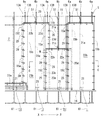
ビルやマンション等の建物の外壁工事を行う際には、図1,2に示すように建物2の外側に作業用の仮設足場5が設置される。この仮設足場5は、一般的に用いられる既製のものを用い、図1,図2に示すように、外側の支柱6と建物2に固設された内側の支柱7とこれらの支柱6,7を連結する作業床板8等とからなり、その支柱6,7は図1に示すように建物2の壁面に平行する左右方向(X−X方向)に複数本所定の間隔で設置されている。
1 to 5 show a first embodiment of the present invention.
When performing outer wall construction of a building such as a building or a condominium, a
前記仮設足場5の外側の支柱6の上部は、建物2の屋上より上方の位置に突出している。該外側の支柱6において、後述する養生シートの相互の重合部に位置する支柱を6aとし、該支柱6a間の中央に位置する外側の支柱を6bとする。
The upper part of the column 6 outside the
前記外側の支柱6aの上部には、図2及び図3に示すように、支持部材であるアーム9が、建物2に対して外側方向に向って水平状態に所定長突出させて固設されている。該アーム9は、前記の外側の支柱6aの全てに設けるか或いは必要な支柱6aに設けて、建物2の左右方向(X−X方向)において複数本設けられている。
As shown in FIGS. 2 and 3, an
前記アーム9間には一方の支持杆である内側パイプ10が横架され、該内側パイプ10は、クランプ12によりアーム9に固定されて保持されている。該内側パイプ10は、図1,図3に示すように、建物2の内外方向(図3においてY−Y方向)における支柱6aより外側に位置して、建物2の左右方向に水平姿勢で配置されており、また、必要な本数を用いて建物2の左右方向における必要な長さ、位置に設けられている。
An
前記アーム9間には、更に、他方の支持杆である外側パイプ11が、前記内側パイプ10より外側に所定量離間して横架されており、該外側パイプ11はクランプ12aによりアーム9に固定されて保持されている。該外側パイプ11は、図1に示すように建物2の左右方向に水平姿勢で配置され、かつ、必要な本数を用いて建物2の左右方向における必要な長さにわたって設けられている。
Between the
前記外側パイプ11には、前記支柱6a部、すなわち、アーム9を中心とする左右方向の両側に位置して2個の支持部材13A,13Bが固着されている。該両支持部材13Aと13Bとの間の間隔は、後述する養生シート23a,23b相互の左右方向における重合部Wの間隔と略同等に設定されている。更に、前記両支持部材13A,13Bは、図1に示すように、複数の外側の支柱6a部毎に設けられ、隣接する一方の外側の支柱6a部における支持部材13Aと他方の外側の支柱6a部における支持部材13Bとの左右方向の間隔が、後述する養生シートの左右方向の長さと略同等に設定されている。
Two support members 13 </ b> A and 13 </ b> B are fixed to the
前記両支持部材13A,13Bは、これを外側パイプ11に固着するクランプ13aと、このクランプ13aの下部に固設された連結板13bとからなる。
The
そして、前記一方の支持部材13Aの連結板13bに第1のガイド部材である第1のガイドワイヤ15aの上端が連結されて、該ガイドワイヤ15aが垂設保持され、他方の支持部材13Bの連結板13bに第2のガイド部材である第2のガイドワイヤ15bの上端が連結されて、該ガイドワイヤ15bが垂設保持され、両ガイドワイヤ15a,15bが平行に垂設されている。両ガイドワイヤ15a,15bの上端は、実施例では1本の外側パイプ11に設けられているが、夫々別々の外側パイプ11に設けてもよく、建物2の壁面に略平行する同一直線上に配置されている。
Then, the upper end of the
前記アーム9、パイプ10,11が、仮設足場5から外側へ突出した支持手段Gを構成し、該支持手段Gに、前記各ガイドワイヤ15a,15bが垂設されている。
The
したがって、図1及び図3に示すように、第1のガイドワイヤ15aが後述する一方の養生シート23aの左側の側部23cに近接して垂設し、第2のガイドワイヤ15bが後述する他方の養生シート23bの右側の側部23dに近接して垂設される。
Accordingly, as shown in FIG. 1 and FIG. 3, the
前記第1のガイドワイヤ15aと第2のガイドワイヤ15bの下端側は、夫々、図2に示すように、金車(滑車)49,49を通り、緊張器50,50を介して仮設足場5の下部に連結されており、緊張器50,50により両ガイドワイヤ15a,15bを強く張って、該両ガイドワイヤ15a,15bが風により揺動することを抑制している。また、前記両ガイドワイヤ15a,15bの金車49,49は、建物2の壁面に略平行する同一直線上に配置されている。すなわち、図2において、第1のガイドワイヤ15aの金車49と同様の第2のガイドワイヤ15bの金車49(図示せず)が、紙面の裏側部において、第1のガイドワイヤ15aの金車49と同軸上に設けられている。また、図1において、前記金車49と緊張器50は省略されている。
As shown in FIG. 2, the lower ends of the
前記内側パイプ10には、前記支柱6a部、すなわち、アーム9を中心とする左右方向の一側に位置して、図の実施例では、前記第1のガイドワイヤ15a側に位置して支持部材13Cが固着されている。該支持部材13Cは、後述する閉塞板25の先部25bの上部に位置するように固着されている。該支持部材13Cは、これを内側パイプ10に固着するクランプ13aと、このクランプ13aの下部に固設された連結板13bとからなる。
The
そして、前記支持部材13Cの連結板13bに第3のガイド部材である第3のガイドワイヤ15cの上端が連結され、該ガイドワイヤ15cが垂設保持されている。すなわち、第3のガイドワイヤ15cは、支持手段Gである内側パイプ10に垂設されている。
And the upper end of the
したがって、図3に示すように、第3のガイドワイヤ15cが後述する閉塞片25の先部25bに近接して垂設される。
Therefore, as shown in FIG. 3, the
前記第3のガイドワイヤ15cの下端側は、図2に示すように、緊張器50を介して仮設足場5の下部に連結されており、緊張器50により該ガイドワイヤ15cを強く張って、該第3のガイドワイヤ15cが風により揺動することを抑制している。
As shown in FIG. 2, the lower end side of the
前記第1〜第3のガイドワイヤ15a〜15cは、前記各支柱6aの部分、すなわち、隣接する養生シート23a,23bの相互の重合部毎に設けられている。なお、建物2の左右方向の端部に配置される養生シート、例えば、図1の右端部の養生シートの非重合部側(右端)は、第2のガイドワイヤ15bのみが垂設されている。
The first to
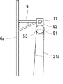
前記支持手段Gを構成する外側パイプ11には、図1に示すように、隣接する一方の養生シート23aの中間部に位置して金車(滑車)51が設けられている。該金車51は、図2及び図5に示すように、前記外側パイプ11に支板52を貫通して垂設し、該支板52に水平軸53によって回転自在に設けられている。なお、前記支柱6bに前記のアーム9を固設して、該アーム9に金車51を設けてもよい。
As shown in FIG. 1, the
また、前記仮設足場5の下部に固設した載置台(ステージ)16上には、一方の養生シート23aの中間に位置して昇降駆動手段である手動或いは電動のウインチ21が設置されている。
In addition, a manual or
そして、隣接する一方の養生シート23a側の昇降用のワイヤ21aを前記ウインチ21に巻回してその一端側21cを前記金車51の上側に掛けて下降させるとともに、その下降端に一方の支持パイプ(支持杆)22aを連結して略水平姿勢に、かつ昇降可能に支持し、他端側21dが図2に示すように収納部54に自由に出入り可能に納められている。また、前記電動のウインチ21は、昇降スイッチ61により作業者が昇降操作できるようになっている。
And the
また、隣接する他方の養生シート23b側にも前記と同様に、金車51、ウインチ21、昇降用のワイヤ21aが、前記一方の養生シート23a側とは独立して設けられ、その昇降用のワイヤ21aの金車51から下降した下降端に他方の支持パイプ(支持杆)22bを連結して略水平姿勢に、かつ昇降可能に支持している。
Similarly, the
前記各支持パイプ22a,22bの左右方向の長さは、隣接する一方の支柱6a部の第1のガイドワイヤ15aと他方の支柱6a部の第2のガイドワイヤ15bに近接して納まる長さに、すなわち、1枚の養生シート23a,23bの左右方向の長さと略同長に形成されている。そして、一方の支持パイプ22aの一方の側部22cと他方の支持パイプ22bの他方の側部22dは、図3に示すように、相互に前後に位置するようになっている。
The lengths of the
前記両支持パイプ22a,22bには、図3に示すように、後述する養生シート23a,23bを吊り下げる支持金具24が、複数個、適宜間隔を有して設けられている。
As shown in FIG. 3, the
次に養生シートについて説明する。
養生シートは、前記仮設足場5の外側において、建物2の左右方向に複数枚に分割されて建物2を被覆するもので、建物の外壁塗装作業時等に用いられる周知の折曲可能なシート、例えば、メッシュ素材からなるシートを用いる。
Next, the curing sheet will be described.
The curing sheet is divided into a plurality of sheets in the left-right direction of the
実施例に示す養生シート23a,23bは、その縦寸法が建物2の最上段から前記シート載置板16までの全域を覆う長さに設定され、横寸法(左右方向の寸法)が、前記隣接する一方の外側の支柱6a部における第1のガイドワイヤ15aと、他方の外側の支柱6a部における第2のガイドワイヤ15bとの間に収まり、かつ、両側端が両ガイドワイヤ15a,15bに近接する長さに設定されている。
In the
各養生シート23a,23bの夫々の上端部と両側端部には複数の取付穴28が所定の間隔で形成されており、該取付穴28にはリング(実施例ではカラビナを使用)29が挿通して備えられている。
A plurality of mounting
そして、隣接する一方の養生シート23aの上端縁に備えたリング29を、前記一方の支持パイプ22aに備えた支持金具24に連結して、該一方の養生シート23aを支持パイプ22aで吊り下げ支持することにより、一方の養生シート23aが仮設足場5の外側において建物2の左右方向に張設されている。また、該一方の養生シート23aの左側の側部23cに備えたリング29を、前記第1のガイドワイヤ15aに上下移動可能に遊嵌し、右側の側部23dに備えたリング29を前記第2のガイドワイヤ15bに上下移動可能に遊嵌して、一方の養生シート23aが、両ガイドワイヤ15a,15bに係合して、該両ガイドワイヤ15a,15bに案内されて上下方向に移動可能に備えられている。
Then, a
また、同様に、隣接する他方の養生シート23bの上端縁に備えたリング29を、前記他方の支持パイプ22bに備えた支持金具24に連結して、該他方の養生シート23bを支持パイプ22bで吊り下げ支持することにより、他方の養生シート23bが仮設足場5の外側において建物2の左右方向に張設されている。また、該他方の養生シート23bの左側の側部23cに備えたリング29を第1のガイドワイヤ15aに上下移動可能に遊嵌し、右側の側部23dに備えたリング29を第2のガイドワイヤ15bに上下移動可能に遊嵌して、他方の養生シート23bが、両ガイドワイヤ15a,15bに係合して、該両ガイドワイヤ15a,15bに案内されて上下方向に移動可能に備えられている。
Similarly, a
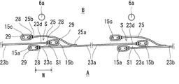
前記の構成により、一方の養生シート23aの一方の側部23cが、他方の養生シート23bの他方の側部23dの外側に位置して、すなわち、この両側部23c,23dが建物2の内外方向(Y−Y方向)において重合し、重合部Wを構成している。
With the above configuration, one
これにより、この重合部Wにおいて、側部23cが外側Aに配置され、側部23dが内側Bに配置されている。
Thereby, in this superposition | polymerization part W, the
なお、前記両養生シート23a,23bの下端縁は、固定、自由端のいずれでもよい。
前記各養生シート23a,23bの左右方向のいずれか一方の側部、すなわち、重合部Wにおいて内外に位置する側部23c,23dのいずれか一方の側部、図においては一方の養生シート23aの側部23c側には、その裏面側(建物側)に位置して閉塞片25が、その基部25aを固着して設けられている。該閉塞片25は、前記養生シート23a,23bと同材で、かつ、上下方向に長い帯状に形成されて、その基端側25aが養生シート23aに固着されている。該閉塞片25は、図の実施例では、上下方向の長さが養生シート23a,23bの上下方向の略全長にわたる長さに設定され、左右方向の幅が図4に示すように、前記重合部Wの左右方向の幅より長く設定されている。更に、該閉塞片25は、図3及び図4に示すように、その基端部25aから、前記重合部Wにおける他方の養生シート23bの内側(建物2側)、すなわち、他方の養生シート23bの側部23dにおける一方の養生シート23aと対向する面と反対側の面に重合するように配置され、その先部25bを、側部23cの先端よりも長くして、前記第3のガイドワイヤ15cに昇降可能に係合している。
The lower end edges of the
Either one of the side portions of the
前記閉塞片25の先部25bと第3のガイドワイヤ15cとの係合は、閉塞片25の先部25bに、上下方向に適宜間隔を有して取付穴28を形成し、該取付穴28にリング(カラビナ)29を備え、該リング29を第3のガイドワイヤ15cに遊嵌して、閉塞片25の先部25bが第3のガイドワイヤ15cに案内されて上下方向に移動可能に係合している。
The engagement between the
前記の構成により、一方の養生シート23aにおける側部23cと閉塞片25間に、他方の養生シート23bが挿入する側と上下側が開口する挿入部(隙間)Sが形成され、該挿入部S内に、他方の養生シート23bの一方の側部23dと第2のガイドワイヤ15bが介在され、かつ、一方の養生シート23a及び閉塞片25と他方の養生シート23bとが相対的に上下方向に摺動可能に、すなわち、相対的に昇降可能に構成されている。
With the above-described configuration, an insertion portion (gap) S is formed between the
したがって、前記重合部W部には、図3及び図4に示すように3枚のシートが重合し、これらの間で形成される隙間Sは、上方から見て折り返しのあるU状に形成される。この隙間Sは、図面では分かりやすいように幅広く示したが、実際には、養生シート23bに対して養生シート23aと閉塞片25が近接して、これらの間の間隔が狭くなるように設定されている。また、前記両ガイドワイヤ15a,15bの内外方向の位置も、分かりやすいように実際よりも離して記載されている。
Therefore, as shown in FIG. 3 and FIG. 4, three sheets are overlapped in the overlapping portion W, and a gap S formed between them is formed in a U shape that is folded when viewed from above. The The gap S is shown broadly so as to be easily understood in the drawing, but actually, the curing
各養生シートは、その一方側、例えば図1における各養生シート23a,23bの左側部に閉塞片25を有し、図1における右端の養生シート23bの左側の前記挿入部S内に中央部の養生シート23aの右側部を挿入し、該中央部の養生シート23aの左側の前記挿入部S内に左側の養生シート23bの右側部を挿入し、これをくり返すようにして、複数の養生シートが建物2の左右方向に配設されている。
Each curing sheet has a
次に使用方法について説明する。
外壁工事の作業、例えば、仮設足場5での塗装作業時には、各昇降駆動手段であるウインチ21を巻き上げして、各支持パイプ22a,22bを上昇させ、ガイドワイヤ15a,15bを案内として各養生シート23a,23bの上端を屋上付近まで個々に上昇させ、その上昇位置を、適宜手段、例えばウインチ21の回転を固定したり、支持パイプ22a,22bを外側パイプ11に締結して固定する。また、この上昇時には、各閉塞片25も、第3のガイドワイヤ15cに案内されて上昇する。
Next, the usage method will be described.
At the time of outer wall construction work, for example, painting work on the
これにより、仮設足場5の外側の全面を各養生シート23a,23bにより被覆することができる。更に、各養生シート23a,23b間に重合部Wが形成されるとともに、該重合部での隙間Sが上方から見て折り返しのあるU状に形成されるため、養生シートの内側で飛散した塗料が、隣接する養生シートの間から外側へ飛散することが防止される。また、両ガイドワイヤ15a,15bの上端の相互及び下部の相互が、夫々建物2の壁面に略平行する同一直線上に配置されていることから、隣接する養生シート23a,23bの上端、すなわち、両支持パイプ22a,22bを上下に相対的にずらした場合には、重合部Wにおける一方の側部23cと他方の側部23dが、接近し、これらの隙間S1が極めて小さくなり、この隙間S1での塗料の飛散防止を高めることができる。
Thereby, the entire outer surface of the
また、その日の作業が終了した際、或いは工事の休日において、開放したい養生シート、例えば、図1において、養生シート23aを下降する場合には、その養生シート用のウインチ21を巻き戻して、その支持パイプ22aを自重で下降させる。これにより、その養生シート23aは、第1,第2のガイドワイヤ15a,15bに案内されて下降(図1の右から2つ目の状態)し、シート載置板16上に折り畳まれて載置される(図1の左端の状態)。
In addition, when the work of the day is completed or on a construction holiday, when the curing sheet to be opened, for example, in FIG. 1, the curing
また、養生シート23bを開放する場合も前記と同様の作業により下降し、かつ載置板16上に折り畳まれて載置される。
Further, when the
前記の養生シート23a,23bの昇降作業時には、各養生シート23a,23bは、その両側端部が両ガイドワイヤ15a,15bに摺動可能に案内されてスムーズに昇降し、また、閉塞片25も第3のガイドワイヤ15cに摺動可能に案内されて、スムーズに昇降し、容易かつ、確実な昇降作業が行える。
At the time of raising / lowering the
更に、閉塞片25は、その基部25aが養生シート23aに固着され、先部25bが第3のガイドワイヤ15cに支持されるため、閉塞片25が強い風で煽られることを防止できる。
Furthermore, since the
更に、閉塞片25が養生シートの内側に配置されるため、強い風が閉塞片25に当ることを抑制し、閉塞片25が風で煽られることを抑制できる。
Furthermore, since the
また、各養生シート23a,23bを下降して開放させた際には、各養生シート23a,23bの全体を建物2の下部、例えば図のシート載置板16上に降ろすことができることから、前記従来のように、養生シートを支柱に束ねておくものに比べて、非作業時の見栄えを良くし、かつ、日光の妨げを少なくすることができる。
Further, when the
更に、各養生シート23a,23bの開閉が個々に行えるので、建物2内の居住者の有無や要望により、簡単に各養生シート毎に上昇状態や下降状態にすることができる。
Furthermore, since each curing
なお、前記実施例では、前記昇降用ワイヤ21aを昇降駆動手段であるウインチ21で昇降するようにしたが、ウインチを使用することなく、昇降用ワイヤ21aを作業者が手で直接持って昇降してもよい。
In the above embodiment, the elevating
図6乃至図8は本発明の実施例2を示す。
本実施例2は、前記の隣接する一方の養生シート23a又は他方の養生シート23b又は双方の養生シート23a,23bを、それぞれ複数個の分割シートで1セットの養生シート33として構成するとともに、この1セットの分割養生シートを1セットとして同時に昇降させるようにしたものである。
6 to 8 show a second embodiment of the present invention.
In the second embodiment, the adjacent one of the
図6に示すように、本実施例2では、隣接する一方の養生シート23aを左側の分割養生シート33aと右側の分割養生シート33bで1セットの養生シート33として構成し、他方の養生シート23bを、左側の分割養生シート33aと右側の分割養生シート33bで1セットの養生シート33として構成している。
As shown in FIG. 6, in Example 2, one
そして、一方の養生シート23aにおける両分割シート33aと33bは、1本の一方の支持パイプ22aにより前記実施例1と同様に支持され、他方の養生シート23bにおける両分割シート33aと33bは、1本の他方の支持パイプ22bにより前記実施例1と同様に支持されている。
The two divided
また、一方の養生シート23aの左側の側部23cと他方の養生シート23bの右側の側部23dは前記のように重合している。
Further, the
前記分割養生シート33a,33bからなる一方の養生シート23aの左側の側部23cには、前記実施例1と同様に閉塞片25が設けられ、分割養生シート33a,33bからなる他方の養生シート23bの左側の側部23dは、前記一方の養生シート23aの前記隙間Sに前記実施例と同様に挿入されている。
The
すなわち、隣接する両養生シート23a,23bの側部は前記実施例1と同様の構成に形成されて重合されている。
That is, the side portions of the
外側パイプ11には、前記一方の養生シート23aの左側の側部23cに位置して前記実施例1と同様に第1のガイドワイヤ15aが垂設され、右側の側部23dに位置して前記実施例1と同様に第2のガイドワイヤ15bが垂設されている。
In the
更に、外側パイプ11には、前記他方の養生シート23bの右側の側部23dに位置して前記実施例1と同様に第2のガイドワイヤ15bが垂設され、左側の側部23cに位置して前記実施例1と同様に第1のガイドワイヤ15aが垂設されている。
Further, a
そして、各養生シート23a,23bは前記実施例と同様の構成により、ガイドワイヤ15a,15bに昇降可能に係合している。
The
更に、前記閉塞片25の先部は、前記実施例1と同様に、内側パイプ10に垂設した第3のガイドワイヤ15cに、前記実施例1と同様な構造によって昇降可能に係合している。
Further, as in the first embodiment, the front end of the
すなわち、分割養生シート33a,33bからなる一方の養生シート23aと分割養生シート33a,33bからなる他方の養生シート23bと閉塞片25をガイドワイヤ15a,15b,15cで案内して昇降させる構造と、両養生シート23aと23bとの重合部Wの構造は前記第1実施例1と同様である。
That is, a structure in which one
前記外側パイプ11には、前記実施例1と同様の金車51が、前記の支持パイプ22aの左右部、すなわち、一方の養生シート23aにおける左側の分割シート33aの中央部及び右側の分割養生シート33bの中央部、更に、前記支持パイプ22bの左右部、すなわち、他方の養生シート23bにおける左側の分割シート33aの中央部及び右側の分割養生シート33bの中央部に位置して設けられている。
In the
前記載置板16上には、前記各金車51の下方に位置して、すなわち、各分割養生シートに対応して昇降駆動手段である電動ウインチ21A〜21Dが設けられており、夫々の電動ウインチ21A〜21Dに巻設された昇降用ワイヤ21aの一端側を前記実施例1と同様に金車51の上側に掛けて下降させるとともに、その下降端を前記支持パイプ22a,22bに、これらを相互に独立して昇降するように連結されている。
On the mounting
前記各電動ウインチ21A〜21Dはコントロールボックス60で制御するようになっており、各コントロールボックス60に設けられた昇降スイッチ61を作業者が操作することにより、一方の養生シート23aにおける分割養生シート33a,33bを同期させ、また、他方の養生シート23bにおける分割養生シート33a,33bを同期させて昇降するようになっている。
Each of the
次に、一方の養生シート23aにおける左右の分割養生シート33a,33b相互の連結部について図6乃至図8により説明する。
Next, the connection part between the left and right divided
左右の分割シート33aと33bとの相互の連結部の上部における外側パイプ11には支持金具34が固設され、該支持金具34に第4のガイド部材である第4のガイドワイヤ35が垂設され、その下端が前記載置板16に、前記実施例1と同様に緊張器50を介して仮設足場5の下部に固定されている。
A support fitting 34 is fixed to the
そして、左側及び右側の分割養生シート33a,33bの連結側部に形成した取付穴28,28間にリング(カラビナ)36を挿通して両分割養生シート33a,33bを連結し、更に左側の分割シート33aの取付穴28にリング(カラビナ)29を挿通するとともに、該リング29を前記第4のガイドワイヤ35に遊嵌し、両分割養生シート33a,33bの昇降を第4のガイドワイヤ35で案内するようになっている。
Then, a ring (carabiner) 36 is inserted between the mounting
前記左側の分割養生シート33aと右側の分割養生シート33bのいずれか一方、例えば図6乃至図8の実施例2では右側の分割養生シート33bにおける他の分割養生シート33aとの連結側には、図8に示すように、被覆片37が、その一側部37aを右側の分割養生シート33bに固着し、他側(先部)37bを、養生シート33aの内側(建物側)に延長して備えられている。この他端(先部)37bは、自由端としてもよく、また、雄、雌からなる面ファスナー37cによって養生シート33aに分離可能に止着してもよい。
On one side of the left divided curing
該被覆片37は、その一側部37aから前記取付穴28、両分割養生シート間、左側の分割養生シート33aの取付穴28を越える幅で、かつ、分割養生シート33a,33bの上下長と略同長の、上下方向に長い帯状に形成されている。
The covering
前記分割養生シート33aと33bとの相互の連結部の構造は、他方の養生シート23bの分割養生シート33aと33bにおいても同様である。
The structure of the connecting portion between the divided
その他の構造は前記実施例1と同様である。
次に使用方法について説明する。
Other structures are the same as those of the first embodiment.
Next, the usage method will be described.
本実施例2においては、一方の養生シート23a側のコントローラ60の昇降スイッチ61を作業者が昇降操作することにより、一方の養生シート23aの両分割養生シート33a,33bを1セットとして同時に昇降できる。また、他方の養生シート23bの両分割養生シート33a,33bも1セットとして同様に昇降できる。
In the second embodiment, when the operator operates the lifting
また、両養生シート23a,23b間の重合部Wは前記実施例1と同様に構成されているため、相互に上下に摺動して、各1セットの養生シート毎の昇降が可能である。
Further, since the overlapping portion W between the curing
本実施例2においては、前記実施例1と同様の効果を発揮するとともに、2枚の分割養生シートを同時に昇降できるため、前記実施例1に比べて、一度に開閉する養生シートを広くし、一世帯において窓側の部屋数が多い場合に有効である。 In the present Example 2, while exhibiting the same effect as the Example 1, since the two divided curing sheets can be moved up and down at the same time, compared with the Example 1, the curing sheet that opens and closes at a time is widened, This is effective when the number of rooms on the window side is large in one household.
更に、分割養生シート間に設けた被覆片37により、該分割養生シート間の隙間から塗料等が外部へ飛散することも防止できる。
Furthermore, the
なお、本実施例2においては、各養生シートを2枚の分割養生シートで構成したが3枚以上の複数で構成してもよい。 In the second embodiment, each curing sheet is composed of two divided curing sheets, but may be composed of a plurality of three or more.
図9及び図10は本発明の実施例3を示す。
前記実施例1及び2は、本発明を仮設足場の外側に配設される養生シートに適用したものであるが、本実施例3は、仮設足場を設けることなく、建物の外側で作業用ゴンドラを昇降して塗装等の作業を行う場合において、その作業用ゴンドラの外側に配設される養生シートに本発明を適用したものである。
9 and 10 show Embodiment 3 of the present invention.
In the first and second embodiments, the present invention is applied to a curing sheet disposed outside the temporary scaffold. However, in the third embodiment, a working gondola is provided outside the building without providing a temporary scaffold. The present invention is applied to a curing sheet disposed on the outside of the working gondola when the work such as painting is performed by moving up and down.
図9及び図10において、建物2の外側に作業用ゴンドラの昇降用空間70を設けて、その外側に前記実施例1の養生シート23a,23b又は前記実施例2の養生シート33a,33b及び前記各ガイドワイヤー15a〜15c等が配置されている。
9 and 10, a working
前記作業用ゴンドラの昇降用空間70には、作業用ゴンドラ71が配置され、該作業用ゴンドラ71は、建物2側に一端が固定されたワイヤ72の他端側が作業用ゴンドラ71に設けた昇降用のモータのプーリ(図示せず)に巻かれ、該昇降用のモータの正逆回転により、昇降するようになっており、周知の作業用ゴンドラである。
A
前記建物2の上部には、支持手段を構成するアーム9が建物2から、前記作業用ゴンドラの昇降用空間70の上部を越えて外側へ突出して設けられており、該アーム9は前記実施例1,2のアーム9に相当し、該アーム9の基端は取付部材73により建物2に取外し可能に固定されている。該アーム9の先部には、前記実施例と同様に、すなわち、図10に示すように、内側パイプ10、外側パイプ11を有し、これらが前記と同様に支持手段Gを構成している。そして両パイプ10,11に、前記実施例1,2と同様にガイドワイヤ15a〜15cが垂設されている。したがって、建物2から外側へ突出した支持手段Gに、各ガイドワイヤ15a〜15cが垂設されている。そして、前記の養生シート23a,23b又は33a,33bが、前記実施例と同様にガイドワイヤ15a,15bに前記と同様に昇降可能に係合している。
At the upper part of the
さらに、前記と同様に、一方の養生シートに設けられた閉塞片25の先部25bがガイドワイヤ15cに昇降可能に係合している。
Further, similarly to the above, the
そして、前記の各養生シート23a,23b,33a,33b、閉塞片25、被覆片37が、前記実施例1,2と同様の構造で同様に配置され、更に、前記実施例1,2における養生シートの昇降機構も同様に設けられている。
And each said curing
したがって、本実施例3は、前記実施例1,2における仮設足場5を除いた他の構造を有している。前記実施例1,2と同一の部分には前記と同一符号を付してその説明を省略する。
Therefore, the third embodiment has another structure excluding the
なお、本実施例3における図9に示す載置台16部は、建物2の下部に直接取付けたステージとしてもよい。
Note that the mounting table 16 shown in FIG. 9 in the third embodiment may be a stage directly attached to the lower part of the
また、緊張器50はガイドワイヤ15a〜15cの上部側に設けてもよい。
本実施例3においては、作業用ゴンドラの昇降用空間70の外側に、前記実施例1,2の仮設足場以外の構造からなる前記の養生シート等を設けたので、作業用ゴンドラで塗装等を行う場合に、該作業用ゴンドラの外側に配置される養生シートにおいて、前記実施例1,2と同様の作用、効果を発揮することができる。
The
In the third embodiment, the curing sheet or the like having a structure other than the temporary scaffolds of the first and second embodiments is provided outside the lifting
図11は、実施例4を示す。
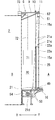
本実施例4は、前記実施例3における支持手段Gを構成する前記アーム9と両パイプ10,11との関係及び作業用ゴンドラ71のワイヤ72と建物2との関係を示す実施例である。
FIG. 11 shows a fourth embodiment.
In the fourth embodiment, the relationship between the
建物2の屋上のパラペット2a上には取付部材73が取外し可能に嵌合固定されている。該取付部材73の上面には角パイプからなる取付筒73aが、建物2の内外方向(Y−Y方向)に向けて固着されている。該取付筒73a内には角筒状のアーム9が摺動可能に嵌合されて、建物2の外方へ突出している。そして該アーム9の先部に前記の内側パイプ10が貫通して支持されている。
On the
また、外側パイプ11も前記と同様な取付部材73、取付筒73a、アーム9によって、アーム9の先部に貫通して支持されている。
Further, the
したがって、アーム9,9を進退調整してネジ73bで固定することにより、パイプ10,11の内外方向の位置調整ができる。
Therefore, the position of the
また、作業用ゴンドラ71のワイヤ72の上端側は、建物2のパラペット2aに取外し可能に固着する取付部材80に腕81を固設し、該腕81の上面の溝部を通じて建物2の屋上部へ案内し、その先部を建物2に設けられた堅牢な物に緊結される。
The upper end side of the
その他の構造は前記実施例3と同様であり、同一部分には同一符号を付してその説明を省略する。 Other structures are the same as those of the third embodiment, and the same portions are denoted by the same reference numerals and the description thereof is omitted.
本実施例4においても前記実施例3と同様の作用、効果を発揮できる。 Also in the fourth embodiment, the same operations and effects as in the third embodiment can be exhibited.
前記第1乃至4実施例では、前記閉塞片25を、重合部Wにおける一方の養生シート23aの側部(重合部の外側Aの側部)23cから、該一方の養生シート23aと重合する他方の養生シート23bの側部(内側Bの側部)23dにおける前記一方の養生シート23aの側部23cと対向する面と反対側の面、すなわち建物側の面である内面側に配置したが、前記他方の養生シート23bの側部(重合部の内側Bの側部)23dから、該他方の養生シート23bと重合する一方の養生シート23aの側部(外側Aの側部)23cにおける前記他方の養生シート23bの側部23dと対向する面と反対側の面、すなわち、建物側と反対の面である外側面に配置してもよい。この場合は、前記第3のガイドワイヤ15cを、前記一方の養生シート23aよりも外側に設け、該第3のガイドワイヤ15cに閉塞片25の先部25bを前記と同様に昇降可能に係合させる。
In the first to fourth embodiments, the
この実施例においても前記と同様の作用、効果を発揮できる。 Also in this embodiment, the same actions and effects as described above can be exhibited.
2 建物
5 仮設足場
15a,15b,15c,35 ガイド部材
21 昇降駆動手段
23a,23b 養生シート
23c,23d 側部
25 閉塞片
25b 先部
33 1セットの養生シート
33a,33b 分割養生シート
37 被覆片
70 作業用ゴンドラの昇降用空間
71 作業用ゴンドラ
2
Claims (6)
The opening and closing of the curing sheet according to any one of claims 1 to 4, wherein a space for raising and lowering the working gondola is provided outside the building, and the curing sheet and the guide member are provided outside thereof. apparatus.
Priority Applications (1)
| Application Number | Priority Date | Filing Date | Title |
|---|---|---|---|
| JP2009062156A JP5285472B2 (en) | 2009-03-15 | 2009-03-15 | Curing sheet opening and closing device |
Applications Claiming Priority (1)
| Application Number | Priority Date | Filing Date | Title |
|---|---|---|---|
| JP2009062156A JP5285472B2 (en) | 2009-03-15 | 2009-03-15 | Curing sheet opening and closing device |
Publications (2)
| Publication Number | Publication Date |
|---|---|
| JP2010216112A JP2010216112A (en) | 2010-09-30 |
| JP5285472B2 true JP5285472B2 (en) | 2013-09-11 |
Family
ID=42975226
Family Applications (1)
| Application Number | Title | Priority Date | Filing Date |
|---|---|---|---|
| JP2009062156A Active JP5285472B2 (en) | 2009-03-15 | 2009-03-15 | Curing sheet opening and closing device |
Country Status (1)
| Country | Link |
|---|---|
| JP (1) | JP5285472B2 (en) |
Families Citing this family (2)
| Publication number | Priority date | Publication date | Assignee | Title |
|---|---|---|---|---|
| JP6452995B2 (en) * | 2014-08-27 | 2019-01-16 | 日本セイフティー株式会社 | Installation method of construction sheet and equipment used for this method |
| JP6453624B2 (en) * | 2014-11-25 | 2019-01-16 | 文化シヤッター株式会社 | Shutter guide rail structure |
Family Cites Families (5)
| Publication number | Priority date | Publication date | Assignee | Title |
|---|---|---|---|---|
| JPS574212Y2 (en) * | 1976-12-13 | 1982-01-26 | ||
| JPS5614141U (en) * | 1979-07-12 | 1981-02-06 | ||
| JPH0743433U (en) * | 1993-12-29 | 1995-08-22 | 株式会社ダイケン | Device for suspending shielding sheets when repairing wall surfaces |
| JP2002115399A (en) * | 2000-10-10 | 2002-04-19 | Nihon Bisoh Co Ltd | Curing device for external wall of building |
| JP2006226090A (en) * | 2005-02-16 | 2006-08-31 | Hitoshi Arakawa | Scattering prevention connection sheet |
-
2009
- 2009-03-15 JP JP2009062156A patent/JP5285472B2/en active Active
Also Published As
| Publication number | Publication date |
|---|---|
| JP2010216112A (en) | 2010-09-30 |
Similar Documents
| Publication | Publication Date | Title |
|---|---|---|
| KR102618795B1 (en) | Methods of mounting panels for suspended ceilings or similar and fabric on the frame of suspended ceilings or similar | |
| JP5285472B2 (en) | Curing sheet opening and closing device | |
| JP2010159617A (en) | Opening-closing device for curing sheet | |
| JP2008110863A (en) | Car top safety fence device of elevator | |
| JP3052246B2 (en) | Fall prevention device for wall work | |
| JP6321938B2 (en) | Installation method of construction sheet and equipment used for this method | |
| JP7033345B1 (en) | Temporary enclosure curing device | |
| WO2015003474A1 (en) | Outdoor window shade | |
| JP5666212B2 (en) | Device for preventing scattering in buildings | |
| JP3416541B2 (en) | How to attach the switch body of the switchgear | |
| US11134652B2 (en) | Retractable curtain for livestock structures | |
| EP1914361A1 (en) | Outdoor framework structure for awnings | |
| JP4167377B2 (en) | Rainfall installation method for unit housing, tent | |
| JP2021173042A (en) | Hanging tool and hanging method of shutter curtain in building shutter device | |
| KR102491378B1 (en) | Removable Fall Prevention Cradle | |
| KR100875145B1 (en) | Multi-stage ladder | |
| JP3177405U (en) | Bird net | |
| JP2001140473A (en) | Curing apparatus | |
| JP2011168963A (en) | Opening/closing system for curing sheet of scaffold | |
| JP2003010566A (en) | Curtain apparatus for stage facility | |
| JP2000282677A (en) | Outer face work device for building | |
| JP2506504Y2 (en) | Panel shutter | |
| JP4873841B2 (en) | Solar shading device | |
| JP2013238012A (en) | External shade | |
| JP2002332755A (en) | Roof for multipurpose house |
Legal Events
| Date | Code | Title | Description |
|---|---|---|---|
| A621 | Written request for application examination |
Free format text: JAPANESE INTERMEDIATE CODE: A621 Effective date: 20120228 |
|
| A977 | Report on retrieval |
Free format text: JAPANESE INTERMEDIATE CODE: A971007 Effective date: 20130318 |
|
| TRDD | Decision of grant or rejection written | ||
| A01 | Written decision to grant a patent or to grant a registration (utility model) |
Free format text: JAPANESE INTERMEDIATE CODE: A01 Effective date: 20130528 |
|
| A61 | First payment of annual fees (during grant procedure) |
Free format text: JAPANESE INTERMEDIATE CODE: A61 Effective date: 20130531 |
|
| R150 | Certificate of patent or registration of utility model |
Ref document number: 5285472 Country of ref document: JP Free format text: JAPANESE INTERMEDIATE CODE: R150 |
|
| R250 | Receipt of annual fees |
Free format text: JAPANESE INTERMEDIATE CODE: R250 |
|
| R250 | Receipt of annual fees |
Free format text: JAPANESE INTERMEDIATE CODE: R250 |
|
| R250 | Receipt of annual fees |
Free format text: JAPANESE INTERMEDIATE CODE: R250 |