JP5285146B2 - Fail safe device and method for disposing of pyrotechnic safety device of automobile - Google Patents
Fail safe device and method for disposing of pyrotechnic safety device of automobile Download PDFInfo
- Publication number
- JP5285146B2 JP5285146B2 JP2011510590A JP2011510590A JP5285146B2 JP 5285146 B2 JP5285146 B2 JP 5285146B2 JP 2011510590 A JP2011510590 A JP 2011510590A JP 2011510590 A JP2011510590 A JP 2011510590A JP 5285146 B2 JP5285146 B2 JP 5285146B2
- Authority
- JP
- Japan
- Prior art keywords
- control device
- signal
- auxiliary
- auxiliary control
- basic
- Prior art date
- Legal status (The legal status is an assumption and is not a legal conclusion. Google has not performed a legal analysis and makes no representation as to the accuracy of the status listed.)
- Active
Links
- 238000000034 method Methods 0.000 title claims description 40
- 238000010304 firing Methods 0.000 claims description 29
- 238000004891 communication Methods 0.000 claims description 17
- 230000008569 process Effects 0.000 description 9
- 230000006870 function Effects 0.000 description 7
- 239000003990 capacitor Substances 0.000 description 6
- 238000011161 development Methods 0.000 description 5
- 238000010586 diagram Methods 0.000 description 5
- 230000033228 biological regulation Effects 0.000 description 4
- 239000002699 waste material Substances 0.000 description 4
- 208000027418 Wounds and injury Diseases 0.000 description 3
- 230000006378 damage Effects 0.000 description 3
- 208000014674 injury Diseases 0.000 description 3
- 230000000737 periodic effect Effects 0.000 description 3
- 230000002093 peripheral effect Effects 0.000 description 3
- 210000003127 knee Anatomy 0.000 description 2
- 230000006837 decompression Effects 0.000 description 1
- 230000007423 decrease Effects 0.000 description 1
- 238000011156 evaluation Methods 0.000 description 1
- 230000007246 mechanism Effects 0.000 description 1
- 238000012544 monitoring process Methods 0.000 description 1
- 238000012545 processing Methods 0.000 description 1
- 230000004044 response Effects 0.000 description 1
- 230000008054 signal transmission Effects 0.000 description 1
- 230000011664 signaling Effects 0.000 description 1
Images


Classifications
-
- F—MECHANICAL ENGINEERING; LIGHTING; HEATING; WEAPONS; BLASTING
- F42—AMMUNITION; BLASTING
- F42B—EXPLOSIVE CHARGES, e.g. FOR BLASTING, FIREWORKS, AMMUNITION
- F42B33/00—Manufacture of ammunition; Dismantling of ammunition; Apparatus therefor
- F42B33/06—Dismantling fuzes, cartridges, projectiles, missiles, rockets or bombs
-
- B—PERFORMING OPERATIONS; TRANSPORTING
- B60—VEHICLES IN GENERAL
- B60R—VEHICLES, VEHICLE FITTINGS, OR VEHICLE PARTS, NOT OTHERWISE PROVIDED FOR
- B60R21/00—Arrangements or fittings on vehicles for protecting or preventing injuries to occupants or pedestrians in case of accidents or other traffic risks
- B60R21/01—Electrical circuits for triggering passive safety arrangements, e.g. airbags, safety belt tighteners, in case of vehicle accidents or impending vehicle accidents
- B60R21/017—Electrical circuits for triggering passive safety arrangements, e.g. airbags, safety belt tighteners, in case of vehicle accidents or impending vehicle accidents including arrangements for providing electric power to safety arrangements or their actuating means, e.g. to pyrotechnic fuses or electro-mechanic valves
-
- B—PERFORMING OPERATIONS; TRANSPORTING
- B60—VEHICLES IN GENERAL
- B60R—VEHICLES, VEHICLE FITTINGS, OR VEHICLE PARTS, NOT OTHERWISE PROVIDED FOR
- B60R21/00—Arrangements or fittings on vehicles for protecting or preventing injuries to occupants or pedestrians in case of accidents or other traffic risks
- B60R21/01—Electrical circuits for triggering passive safety arrangements, e.g. airbags, safety belt tighteners, in case of vehicle accidents or impending vehicle accidents
- B60R2021/01013—Means for detecting collision, impending collision or roll-over
- B60R2021/01027—Safing sensors
Description
本発明は、全体として、火工的安全装置の廃棄、とりわけフェイルセーフな自動車用火工的安全装置の廃棄に関する。 The present invention relates generally to the disposal of pyrotechnic safety devices, and in particular to the disposal of fail-safe automotive pyrotechnic safety devices.
自動車は、通常、自動安全装置を含んでいて、さまざまな火工的安全装置(PSD)および一連の衝突センサを搭載している。万一の自動車衝突の場合には、衝突センサから受信した信号に反応してPSDが作動すなわち展開し、自動車の乗員が被る負傷を和らげる。PSDの例としては、エアバッグ、シートベルト・プリテンショナ、展開可能ロールバー、展開可能ニーボルスタ、展開可能アンチサブマリン装置、「ポップアップ」式歩行者安全フードなどがある。 Automobiles typically include automatic safety devices and are equipped with various pyrotechnic safety devices (PSDs) and a series of crash sensors. In the event of a car crash, the PSD is activated or deployed in response to a signal received from the crash sensor, reducing the injury experienced by the vehicle occupant. Examples of PSDs include airbags, seat belt pretensioners, deployable roll bars, deployable knee bolsters, deployable anti-submarine devices, and “pop-up” pedestrian safety hoods.
自動車の耐用年数の終了時、展開しなかった多数の「生きている」PSDが自動車に残る。PSDの火工的性質のため、多くの国の政府規則で、安全上の理由から、PSDの除去、保管および再利用を禁じている。近年、多くの政府が、展開しなかったPSDを残している自動車の廃棄を禁じる規則をも施行し、今や、自動車廃棄の前に、展開しなかったすべてのPSDを展開させるよう求めている。このような規則の1つは、ISO 26021規約案に盛り込まれていて、自動車拘束システムコントローラが、外部装置からPSD廃棄命令を受信し、それに基づいて作動することを求めている。 At the end of the car's useful life, a number of “live” PSDs that have not been deployed remain in the car. Due to the pyrotechnic nature of PSD, government regulations in many countries prohibit PSD removal, storage and reuse for safety reasons. In recent years, many governments have also enacted rules prohibiting the disposal of cars that have left undeveloped PSDs, and now require that all undeveloped PSDs be deployed prior to car disposal. One such rule is included in the draft ISO 26021 code and requires that the vehicle restraint system controller receive a PSD discard command from an external device and act upon it.
自動車拘束システムの主要な目的は衝突時に自動車の乗員の負傷を和らげることであるから、明白な自動車の衝突状態、すなわち乗員の負傷を引き起こすほど重大な衝突状態が認識された時のみ、PSDを作動させることが望ましい。 The primary purpose of the vehicle restraint system is to relieve vehicle occupant injury in the event of a collision, so the PSD is only activated when an obvious vehicle crash condition is recognized, i.e., a collision condition that is severe enough to cause occupant injury. It is desirable to make it.
PSDの偶発のもしくは不要な展開を防ぐために、自動車拘束システムコントローラは一般に「フェイルセーフ」に設計され、システムの構成要素のうちただの1つも、PSDへ流れる展開電流を生じさせる工程で失敗しないように設計される。全体として、このフェイルセーフ構造は、多数の独立した衝突センサ、ロジック回路評価、および展開コントロールハードウェアをアレンジすることにより実現され、個々の構成要素それぞれが所定の展開状態に達したときしか、展開電流が流れることを許容しない。しかし、自動車拘束システムコントローラのこのフェイルセーフ構造によって、自動車の廃棄に先立って手動で安全にPSDを廃棄することが困難になっている。なぜなら、一般的に、衝突状態を示すセンサ入力がなければ、所定の展開状態にならないからである。 In order to prevent accidental or unwanted deployment of PSDs, automotive restraint system controllers are generally designed “fail-safe” so that only one of the system components does not fail in the process of generating deployment current flowing into the PSD. Designed to. Overall, this fail-safe structure is realized by arranging a number of independent crash sensors, logic circuit evaluation, and deployment control hardware, and can only be deployed when each individual component reaches a predetermined deployment state. Do not allow current to flow. However, this fail-safe structure of the vehicle restraint system controller makes it difficult to manually and safely discard the PSD prior to vehicle disposal. This is because, in general, if there is no sensor input indicating a collision state, a predetermined deployment state is not achieved.
このように、標準的な拘束システム構造は、PSD廃棄用の展開が単一の通信ポートを介して制御されることを求めるISO 26021規約案などの規則とは矛盾している。単一の通信ポートを介した展開を実現するには、関連する制御ロジックが、多くの自動車拘束システムコントローラ内蔵のインターロックおよびリダンダンシを実質的に無視する必要がある。しかしこれにより、仮に個々の構成要素の故障モードが適切に管理されなかった場合には、システムの偶発的な展開の危険性が潜在的に増すことになってしまう。 Thus, the standard restraint system structure is inconsistent with rules such as the ISO 26021 draft code that requires the deployment of PSD discards to be controlled via a single communication port. To achieve deployment via a single communication port, the associated control logic must substantially ignore the interlocks and redundancy built into many automotive restraint system controllers. However, this can potentially increase the risk of accidental system deployment if individual component failure modes are not properly managed.
したがって、ISO 26021規約案などの新しい政府規則に準拠する、火工的安全装置の廃棄のためのフェイルセーフ方法および装置に対するニーズが現存する。 Accordingly, there is a need for fail-safe methods and devices for the disposal of pyrotechnic safety devices that comply with new government regulations such as the ISO 26021 draft code.
本発明の一面において、火工的安全装置の廃棄に関する方法は、基本制御装置および補助制御装置を有する電子制御装置を設けることを含んでよい。補助制御装置はセーフィングモードおよびスクラップモードを含み、初期状態ではセーフィングモードで作動する。補助制御装置は、基本制御装置から第1の所定信号を受信すると、セーフィングモードからスクラップモードに切り換わる。補助制御装置は、補助制御がスクラップモードで作動している間に基本制御装置から第2の所定信号を受信したときのみ、発火する。補助制御装置の発火中に単一のPSDへ展開信号を送信することにより、その単一のPSDを展開させる。 In one aspect of the invention, a method for disposing of a pyrotechnic safety device may include providing an electronic control unit having a basic control unit and an auxiliary control unit. The auxiliary control device includes a safing mode and a scrap mode, and operates in the safing mode in an initial state. The auxiliary control device switches from the safing mode to the scrap mode when receiving the first predetermined signal from the basic control device. The auxiliary control device ignites only when the second predetermined signal is received from the basic control device while the auxiliary control is operating in the scrap mode. The single PSD is deployed by sending a deployment signal to the single PSD during firing of the auxiliary controller.
他の側面において、展開信号は、外部ソースより受信した信号に基づき、基本制御装置からPSDへ送信する。基本制御装置は、外部信号ソースから第1の信号を受信した後に、第1の所定信号を補助制御装置に送信する。基本制御装置は、外部信号ソースから第2の信号を受信した後に、第2の所定信号を補助制御装置に送信する。外部信号ソースはCANベースのテスタとしてよく、補助制御装置とは通信不能である。 In another aspect, the deployment signal is transmitted from the basic controller to the PSD based on the signal received from the external source. After receiving the first signal from the external signal source, the basic control device transmits the first predetermined signal to the auxiliary control device. After receiving the second signal from the external signal source, the basic control device transmits a second predetermined signal to the auxiliary control device. The external signal source may be a CAN-based tester and cannot communicate with the auxiliary controller.
さらに本発明の他の側面において、火工的安全装置の廃棄方法は、基本制御装置のメモリに符号化データを保存することを含んでよい。符号化データは複数の所定信号に相当する。復号キーは、基本制御装置が外部信号ソースから受信する複数の信号に基づいて決定される。第1および第2の所定信号に相当する、符号化データの少なくとも一部分は、この復号キーを使って復号される。 In yet another aspect of the present invention, the pyrotechnic safety device disposal method may include storing encoded data in a memory of the basic controller. The encoded data corresponds to a plurality of predetermined signals. The decryption key is determined based on a plurality of signals received by the basic control device from an external signal source. At least a part of the encoded data corresponding to the first and second predetermined signals is decoded using this decoding key.
本発明の他の側面において、補助制御装置は、廃棄セッションが終了するとセーフィングモードにリセットされ、復号キーおよび復号データが破棄可能となる。 In another aspect of the present invention, the auxiliary control device is reset to the safing mode when the discard session ends, and the decryption key and decryption data can be discarded.
本発明による火工的安全装置の他の処理方法は、基本制御装置および補助制御装置を含む電子制御装置を設けることを含み、補助制御装置はセーフィングモードおよびスクラップモードで作動可能である。補助制御装置がスクラップモードで作動する時、補助制御装置から基本制御装置へ廃棄シードが送信される。廃棄シードに基づいて廃棄キーが計算され、補助制御装置は、基本制御装置が廃棄キーを補助制御装置に送信した時に発火する。火工的装置の発火中に展開信号を単一の火工的装置に送信することにより、その単一の火工的装置が展開する。廃棄キーは、ユニークな定期的メッセージとしてよい。 Another method of processing a pyrotechnic safety device according to the present invention includes providing an electronic control unit including a basic control unit and an auxiliary control unit, the auxiliary control unit being operable in a safing mode and a scrap mode. When the auxiliary controller operates in scrap mode, a waste seed is transmitted from the auxiliary controller to the basic controller. A discard key is calculated based on the discard seed, and the auxiliary controller fires when the basic controller transmits the discard key to the auxiliary controller. Sending a deployment signal to a single pyrotechnic device during firing of the pyrotechnic device deploys that single pyrotechnic device. The discard key may be a unique periodic message.
1つの実施形態では、補助制御装置は展開後に安全化させてよい。また、仮に他の廃棄信号を基本制御装置より受信した場合には、再発火させてよい。第2の火工的装置は、補助制御装置が廃棄信号を受信したときに展開させてよく、補助制御装置の発火中、基本制御装置は火工的装置に展開信号を送信する。 In one embodiment, the auxiliary controller may be secured after deployment. Further, if another discard signal is received from the basic control device, it may be fired again. The second pyrotechnic device may be deployed when the auxiliary control device receives a discard signal, and during firing of the auxiliary control device, the basic control device transmits a deployment signal to the pyrotechnic device.
火工的安全装置の廃棄に関するシステムは、補助制御装置および基本制御装置を有する電子制御装置を含んでよい。基本制御装置は補助制御装置と電気通信を行い、補助制御装置はセーフィングモードおよびスクラップモードで作動するように構成される。また本システムは、補助制御装置および基本制御装置と電気通信を行う火工的安全装置と、基本制御装置と電気通信を行う外部信号装置とを含む。外部信号装置は、補助制御装置と電気通信を行わない。1つの実施形態では、外部信号装置はCANベースのテスタとしてよい。 A system for disposal of pyrotechnic safety devices may include an electronic control unit having an auxiliary control unit and a basic control unit. The basic controller is in electrical communication with the auxiliary controller, and the auxiliary controller is configured to operate in a safing mode and a scrap mode. The system also includes a pyrotechnic safety device in electrical communication with the auxiliary control device and the basic control device, and an external signal device in electrical communication with the basic control device. The external signal device does not perform electrical communication with the auxiliary control device. In one embodiment, the external signaling device may be a CAN-based tester.
補助制御装置は、補助制御装置が基本制御装置から第1の所定信号を受信した時に、セーフィングモードからスクラップモードに切り換わるよう構成される。また補助制御装置は、補助制御装置がスクラップモードで作動している時に基本制御装置から第2の所定信号を受信すると、火工的安全装置を発火させるよう構成される。 The auxiliary control device is configured to switch from the safing mode to the scrap mode when the auxiliary control device receives the first predetermined signal from the basic control device. The auxiliary control device is configured to ignite the pyrotechnic safety device when receiving the second predetermined signal from the basic control device when the auxiliary control device is operating in the scrap mode.
さらに他の一面では、発火後、決まった期間だけ補助制御装置の発火状態を継続させてよい。 In yet another aspect, the ignition state of the auxiliary control device may be continued for a fixed period after ignition.
概要の紹介として以上の各段落を記載したが、後述する特許請求の範囲を制限する意図はない。現状の好ましい実施形態は、他の利点とともに、以下に続く詳細な説明および添付の図面を参照して、最もよく理解可能である。 Although each of the above paragraphs has been described as an introduction to the outline, there is no intention to limit the scope of the claims described below. The presently preferred embodiments, along with other advantages, are best understood with reference to the detailed description that follows and the accompanying drawings.
本発明は、図面と関連した以下の説明を読むことにより、より完全に理解可能である。
「火工的安全装置」もしくは「PSD」という用語は、火工品を含むあらゆる自動車安全拘束のことを指し、例えば、エアバッグ、シートベルト・プリテンショナ、展開可能ロールバー、展開可能ニーボルスタ、展開可能アンチサブマリン装置、「ポップアップ」式歩行者安全フードなどがあるが、これらに限られない。用語「展開」、「展開した」、「廃棄」およびこれらの派生語は、火工的安全装置の発火後の状態、つまり発生した火工ガスが実質的にすべて酸化した状態を指す。 The term “pyrotechnic safety device” or “PSD” refers to any vehicle safety restraint, including pyrotechnics, such as airbags, seat belt pretensioners, deployable roll bars, deployable knee bolsters, deploys Possible anti-submarine devices, “pop-up” pedestrian safety hoods, but are not limited to these. The terms “deployment”, “deployed”, “disposal” and their derivatives refer to the post-ignition state of the pyrotechnic safety device, that is, substantially all of the generated pyrotechnic gas is oxidized.
最近の火工的安全装置は電子制御装置(ECU)を含み、これは一般に2つのハードウェア制御装置、つまり、主要なマイクロコントローラ(MCU)および独立した補助制御装置を利用する。補助制御装置はセーフィングロジックとも呼ばれ、衝突状態を認識し、各PSDを展開させる。一般的に、MCUはマイクロコントローラ衝突アリゴリズムを利用して衝突信号を分析し、衝突の位置および程度を決定する。衝突アルゴリズムが、衝突が十分重大であると判断した場合、MCUは、検知された衝突位置に相当するPSDに展開信号を送信する。補助制御装置は、同時に独立して同衝突信号を分析し、衝突信号を有効にし、セーフィング(発火)をオンにする。PSDの展開を実現するためには、展開信号およびセーフィングが同時に発生しなければならない。 Modern pyrotechnic safety devices include an electronic control unit (ECU), which typically utilizes two hardware control units: a main microcontroller (MCU) and an independent auxiliary control unit. The auxiliary control device is also called safing logic, recognizes the collision state, and develops each PSD. In general, the MCU uses a microcontroller collision algorithm to analyze the collision signal and determine the position and extent of the collision. If the collision algorithm determines that the collision is sufficiently serious, the MCU sends a deployment signal to the PSD corresponding to the detected collision position. The auxiliary controller simultaneously analyzes the collision signal independently, enables the collision signal, and turns on safing (ignition). In order to realize the expansion of the PSD, the expansion signal and safing must be generated simultaneously.
ISO 26021規約案などの政府規則および工業規格では、自動車が道路での使用に適さなくなった時および自動車がスクラップされる時に、展開されなかった、もしくは「生きている」PSDを廃棄するメカニズムをECUが有することを要求する。これらの規則の下では、スクラップ時に、テスタがコントローラ・エリア・ネットワーク(CAN)を介してECUにメッセージ(信号)を送信し、PSDの廃棄を要求する。しかし、CANメッセージはMCUでしか受信されないため、補助制御装置は、テスタメッセージを同時に有効にするための外部入力を持たない。したがって本発明は、外部信号ソースから送信されMCUのみが受信する信号を独立して有効にし、これにより、「スクラップ時」に独立したセーフィングおよびPSDの展開を実現することを目的とする。 Government regulations and industry standards, such as the draft ISO 26021 code, provide a mechanism for discarding PSDs that have not been deployed or “live” when vehicles are no longer suitable for road use and when vehicles are scrapped. Requires that you have. Under these rules, when scrapping, the tester sends a message (signal) to the ECU via the controller area network (CAN) to request the disposal of the PSD. However, since the CAN message is received only at the MCU, the auxiliary controller does not have an external input to enable the tester message at the same time. Accordingly, an object of the present invention is to independently enable a signal transmitted from an external signal source and received only by the MCU, thereby realizing independent safing and PSD deployment at the “scrap time”.
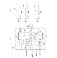
各要素を示す参照番号については、図を参照されたい。図1(a)は、本発明の実施形態による電子制御装置(ECU)100を示している。ECU100は、補助制御装置110、基本マイクロコントローラ(MCU)120およびANDゲート180を含む。補助制御装置110は、メモリに保存された2つの作動モード、つまり、セーフィングモード112およびスクラップモード114を含む。MCU120は、衝突アルゴリズム122およびメモリに保存されたスクラップ管理データ124を含む。スクラップ管理データ124は、好ましくは、MCU120のメモリ内に、実行不能形式にて符号化され保存される。補助制御装置110およびMCU120は、互いに双方向電気通信を行い、補助制御装置110およびMCUは両方とも、自動車のPSDと電気通信を行う(図示せず)。ANDゲート180もまた、MCU120および補助制御装置110と同様、自動車のPSDと電気通信を行う。
Refer to the figure for reference numbers indicating each element. FIG. 1A shows an electronic control unit (ECU) 100 according to an embodiment of the present invention.
補助制御装置110は、セーフィングモード112およびスクラップモード114の2つのうち1つのモードで、自動車のPSDを発火もしくは安全化させるよう構成される。補助制御装置110はまた、MCU120が補助制御装置110に廃棄シード130の要求を送信した時に、廃棄シード130をMCU120に送信するよう構成される。廃棄シード130は、好ましくは、シリアル・ペリフェラル・インタフェース(SPI)を介して、2kHzに等しいかそれ以上のスピードで送信される。補助制御装置110は、CANを介して送信された信号、もしくは、テスタなどの、ECU100の外部ソースから他の通信ラインを受信できないことが好ましい。
The
MCU120は、複数の自動車衝突センサ(図示せず)からの信号、ならびにテスタ(図示せず)などの外部信号ソースからの信号、廃棄シード130を含む補助制御装置110からの信号を受信するよう構成される。MCU120はCANを介して外部信号を受信することが好ましい。しかし、現存するもしくは後に開発されるいかなる電気通信ラインを信号送信に利用してもよいと理解すべきであり、例えばこれらに限られないがイントラネット、ケーライン、もしくはワイヤレス・プロトコルを含む。MCU120はまた、自動車のPSDに信号を送信し、廃棄キー140などの信号を補助制御装置110に送信するよう構成される。信号は、シリアル・ペリフェラル・インタフェース(SPI)を介して送信されることが好ましい。
The
作動に際して、廃棄シード/廃棄キーによる方法を用いて、補助制御装置110がスクラップモード114で作動中に補助制御装置110を発火させてよい。これについての詳細は、図2〜図5を参照して下記に述べる。
In operation, the waste seed / discard key method may be used to ignite the
図1(b)は、補助制御装置110と、ECU100のMCU120とのタイミング動作を示している。時刻t0では、偶発の展開を避けるために、安全化機能150はHIGHであり、発火機能はLOWである。補助制御装置110は、時刻t1で初めて発火機能160を作動させる。これは、セーフィングモード112で作動中に衝突センサ信号がPSD展開要求を満たしていると独立して確認すると同時に行われる。あるいは、スクラップモード114で作動中に廃棄キー信号を受信すると同時に行われる。補助制御装置110が時刻t1で発火する時、安全化はLOWで、発火はHIGHである。補助制御装置110の発火中、つまり時刻t1〜t2の間、MCU120は、時刻t3〜t4間ではHIGHになる展開信号170を送信する。PSDは、展開信号がHIGHでありかつ補助制御装置110の発火機能160がHIGHである場合のみ、展開可能である。展開信号がHIGHであり、発火機能160がLOWであり、安全化機能150がHIGHである場合、PSDは展開できない。図1(b)に見られるように、発火すると、補助制御装置110は所定の時間発火可能である。例えば、補助制御装置が発火したままでいる時間を定義した時刻t1〜t2間のセーフィング・ウィンドウ(発火ウィンドウ)は、およそ0.5ミリ秒からおよそ2ミリ秒の間でよい。好ましくは、補助制御装置110を発火させている時間は、次の数式により計算される。
発火時間=発火リード時間+発火電流時間+発火ラグ時間
FIG. 1B shows a timing operation between the
Ignition time = ignition lead time + ignition current time + ignition lag time
ここで発火リード時間は、補助制御装置110が発火した後に展開信号がPSDに送信されるように決定される。発火リード時間は、例えばおよそは、2ミリ秒からおよそ5ミリ秒の間でよいがこれに限られない。発火電流時間はハードウェアに依存し、パラメータを固定された火工装置に依存する。また、発火電流時間は、およそ0.5ミリ秒からおよそ2ミリ秒の間に設定してよい。発火ラグ時間(発火後の)は、補助制御装置110の発火継続を許容する追加の時間であり、この発火継続によって、PSD展開に必要な時間が所定の発火電流時間では不足することになっても、確実にPSDの展開が完了する。発火ラグ時間は、発火電流時間の複数倍としてよい。例えば、発火ラグ時間は発火電流時間の2倍としてよいが、これに限定されない。無論、セーフィング・ウィンドウは他の手段によって計算してもよく、もしくは、固定時間としてもよいことは理解されるべきである。例えば、発火ラグ時間は、およそ2ミリ秒からおよそ3ミリ秒の固定値であってもよい。
Here, the firing lead time is determined so that the development signal is transmitted to the PSD after the
発火電流は、バッテリにより充電されるコンデンサによって提供してよい。コンデンサに蓄えられたチャージは、新しい発火電流がPSDに送信される度に減少するため、コンデンサは、例えば、16個のPSDのうち12番目のPSDが発火した後、放電させてもよい。この場合、発火命令はSPI経由で送信されるが、実際の発火電流は、コンデンサが十分なボルテージにまで再充電された後に、PSDにのみ送信される。このように、補助制御装置110の発火中に発火信号をPSDに確実に送信するために、また、PSDを確実に展開させるために、補助制御装置110の発火時間は、発火電流時間を超過することが望ましい。さらには、コンデンサは一般に経時劣化するので、発火ラグ時間を、コンデンサの劣化した性能を相殺するために作用させてもよい。
The ignition current may be provided by a capacitor that is charged by a battery. Since the charge stored in the capacitor decreases each time a new firing current is transmitted to the PSD, the capacitor may be discharged after the 12th PSD of 16 PSDs has fired, for example. In this case, the firing command is sent via the SPI, but the actual firing current is sent only to the PSD after the capacitor is recharged to a sufficient voltage. As described above, the firing time of the
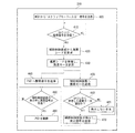
図2は、図1(a)の実施形態に従って、火工的安全装置の廃棄に関するフェイルセーフ方法を表すフローチャート例を示している。工程210において、補助制御装置110、MCU120およびANDゲート180を含むECU100が、パワーオンされる。補助制御装置110は、2つのモード、つまり、セーフィングモード112およびスクラップモード114で作動するよう構成される。MCU120は、メモリ、好ましくはROMを含んでよい。メモリは符号化データ124を保存していて、これは、補助制御装置110のスクラップモードをオンにしたり、PSDの火工的展開を命令したりするのに必要なものであり、好ましくは実行不能形式で保存される。工程220に見られるように、起動時、補助制御装置110はセーフィングモード112に設定され、衝突アルゴリズム122がオンになる。工程230において、MCU120は、スクラップモード114に入るための外部信号をテスタ等から受信したか否かを判定する。
FIG. 2 shows an example flowchart representing a fail-safe method for the disposal of a pyrotechnic safety device in accordance with the embodiment of FIG. In step 210, the
工程240に見られるように、外部信号が受信されなかったら、補助制御装置110はセーフィングモードを維持し、MCU120はスクラップモード114に入るための外部信号を監視し続ける。しかし、スクラップモード114に入るための外部信号を受信したことをMCU120が判定すると、MCU120は、スクラップモード114の入力に関するISO 26021規約案により定義された条件を満たすか否かを判定する。これは工程250に示される。仮に所定の条件を満たしていなかったら、補助制御装置はセーフィングモード112を維持し、MCU120はスクラップモード114に入るための新しい外部信号を監視し続ける。
As seen in
スクラップモード114に入るための所定の条件が満たされた場合、MCU120は、蓄積されたデータに基づく復号キー(図示せず)の組立を開始する。本データは、工程260に見られるように、CANを介して外部信号ソースによって受信された信号を通じてMCU120が受信したものである。復号キーは、外部信号ソースによってMCU120に送信されたCAN信号(メッセージ)の16進値のみから得られることが望ましい。また、外部信号ソースから外部CAN信号を受信する前は、MCU120のメモリ内には復号キーのいずれの部分も含まれていない、すなわち保存されていないことが望ましい。また、スクラップ状態を包括的に認識するのに必要なあらゆるCANメッセージが含まれるように、復号キーを選択することが望ましい。
When a predetermined condition for entering the
工程270において、一旦復号キーの組立が完了すると、MCU120は、MCU120のROMに保存された符号化データ124を、実行可能な形式の指示に復号し、RAMに当該指示をロードする。復号された実行可能な指示には、セーフィング・ハードウェアにて展開制御を定期的に管理するアルゴリズム、火工的展開を命令するための指示、廃棄キー140を計算するための指示、および補助制御装置の作動モードを制御するための所定信号を含めてよい。MCU120は、復号キーの適切さを確認できないことが望ましく、したがって、復号された実行可能な指示の適切さを確認できないことが望ましい。MCU120は、単にCAN信号からの復号キーを組み立て、符号化されたデータ124を復号する。
In
指示がRAMに一旦ロードされると、MCU120は、符号化データ124から復号された所定信号を、復号キーを使って補助制御装置110に送信する。すると補助制御装置110はスクラップモード114をオンにする命令を出す。スクラップモード114に入ると、すべての衝突アルゴリズム122が中断され、補助制御装置110は、衝突センサからの信号の監視を停止する。所定信号は、補助制御装置110に、MCU120から廃棄キー140を受信したときにのみ発火するよう命じる。このことは、図4に関連して後述する。
Once the instruction is loaded into the RAM, the
図3に注目すると、図3は図2のセーフィングモード実行220のフローチャートを示している。これは、非スクラップ状態における補助制御装置110の標準作動モードであり、ECU100がパワーオンされたときの初期モードと同じである。工程300に見られるように、補助制御装置110がセーフィングモード112で作動しているとき、補助制御装置110は、自動車の全体にわたって設置される一連の衝突センサからの信号を監視する(図示せず)。そして、MCU120は、一連の衝突センサからの受信信号を監視するために衝突アルゴリズム122を利用する。当該一連のセンサは、減速力と、その減速力が生じた1または複数の位置とに関して、ECU100へ情報を中継するよう構成される。
Turning attention to FIG. 3, FIG. 3 shows a flowchart of the
工程310、320において、MCU120が衝突センサ信号を受信すると、衝突アルゴリズム122は、当該信号がPSD展開に関する所定のパラメータに適合するか否かを決定する。その間、補助制御装置110は同時かつ独立に、本発明の技術分野で知られている方法によって、上記信号が所定のパラメータに適合するか否かを確認する。所定の要件が満たされない場合は、PSDは展開せず、MCU120は、衝突センサ信号の監視を続ける。
In
工程330、340に見られるように、衝突信号が展開のための所定のパラメータに適合することをMCU120衝突アルゴリズムが判定し、また、衝突信号が展開のための所定のパラメータに適合することを補助制御装置110が独自に確認した場合、MCU120は、ANDゲート180に展開信号を送信する。補助制御装置110が衝突信号を確認すると、補助制御装置110は発火し、補助制御装置110はANDゲート180に発火信号を送信する。補助制御装置110の発火中、ANDゲート180がMCU120からの展開信号および補助制御装置110からの発火信号の両方を受信すると、衝突アルゴリズム122により指定された各PSDに展開信号が送信され、指定された各PSDが展開する(工程350、360)。
As seen in
図4は、図2の工程280に示されるスクラップモード114を実行するためのフローチャートを示す。補助制御装置110は、MCU120が復号キーを用いて復号した所定信号を受信したときのみ、スクラップモード114に入るよう構成される。工程400に見られるように、補助制御装置110がMCU120から復号された所定信号を受信すると、セーフィングモード112の衝突アルゴリズム122は中断され、補助制御装置110は、廃棄キー140を受信したときのみ発火可能となる。補助制御装置110が一旦スクラップモード114に入ると、補助制御装置110は、廃棄キー140受信以外のいかなる手段を通しても発火不能であることが望ましいことに注目されたい。
FIG. 4 shows a flowchart for executing the
工程410において、補助制御装置110がスクラップモード114に入ると、MCU120は、外部信号ソースからの廃棄信号に関してCANを監視し続けることが望ましい。MCU120が外部信号ソースから廃棄信号を受信すると、MCU120は、補助制御装置110に信号を送信し、廃棄シード130を要求する(工程420)。廃棄シード130は、補助制御装置110によりパワーサイクル毎に生成され、もしくは所定の時間間隔で生成される乱数であってよい。
In
工程430において、MCU120は、補助制御装置110から廃棄シード130を受信し、廃棄シード130に基づいた廃棄キー140を計算する。MCU120は、次に、補助制御装置110へ廃棄キー140を送信し、ANDゲート180に展開信号を送信する(工程450、440)。廃棄キー140は、ユニークな定期的メッセージとしてもよい。展開信号は、工程260において復号された実行可能な指示としてよく、もしくは、テスタから受信された廃棄信号に含めてもよい。展開信号および廃棄キー140は、シリアル・ペリフェラル・インタフェース(SPI)を介して、MCUから同時に受信されることが望ましい。
In
補助制御装置110が一旦廃棄キー140を受信すると、補助制御装置110は、MCU120から受信した廃棄キー140が適切か否かを決定する(工程460)。もし、廃棄キー140が適切でなかった場合、補助制御装置110は発火しないままでいて、適切な廃棄キー140に関して監視を続ける(工程465)。しかし、仮に補助制御装置110が適切な廃棄キー140を受信したら、補助制御装置110は発火し、工程470に見られるように、補助制御装置110はANDゲート180に発火信号を送信する。
Once the
工程480、490に見られるように、仮に補助制御装置110の発火中にANDゲート180がMCU120からの展開信号および補助制御装置110からの発火信号の両方を受信すると、外部信号ソースにより要求されたPSDに、展開信号が送信される。補助制御装置110がスクラップモード114で作動している時は、ECU100は、外部信号ソースからの廃棄信号を受信しても、単一のPSDしか展開できないよう制限されることが望ましいことに注意されたい。しかし、仮に廃棄信号が複数同時の展開を要求する場合は、単一の廃棄信号受信と同時に、複数のPSDを展開させてよい。
As seen in
図2および図4に関連して述べられた上記工程は、MCU120が新しい廃棄要求を外部信号ソースから受信する度に繰り返される。さらに、MCU120は復号キーの適切さを確認することができないため、復号された指示の適切さ、復号された所定信号の適切さ、およびCANメッセージ(テスタ)を送信する外部信号ソースの適切さは、補助制御装置110にスクラップモード114をオンにすることを命じる唯一の手段である。このように、補助制御装置110が、MCU120とは独立して発火することにより、偶発の展開の危険性を最小限にする。
The above process described in connection with FIGS. 2 and 4 is repeated each
図5は、補助制御装置110がスクラップモード114で作動する時の、複数の火工的装置の廃棄方法に関するフローチャートを示している。ECU100は、外部信号ソースから受信した廃棄信号ごとに単一のPSDを展開させるよう、制限されている。工程490における単一のPSDの展開に続き、補助制御装置110は、工程510において一時的にオフにされる。補助制御装置110は、補助制御装置110に不適切な信号(たとえば適切な展開キー以外の信号)を送信することによりオフにしてよい。補助制御装置110が一時的にオフにされたあと、MCU120は、スクラップ状態が終了したか否かを監視する。スクラップ状態の終了となる状態の例には、ECU100のリセット、ECU100および外部信号ソース間の通信の喪失、もしくは、パワーの喪失が含まれる。スクラップ状態が終了した場合、工程530に見られるように、補助制御装置110はセーフィングモード112に設定される。そして、復号キー、およびRAMに保存された復号された実行可能な指示は破棄してよい。補助制御装置110が一旦セーフィングモード112に設定されると、補助制御装置110は、図2および図4に関連して上述した工程による以外、スクラップモードに設定不能であることが望ましい。
FIG. 5 shows a flowchart relating to the disposal method of a plurality of pyrotechnic devices when the
しかし、スクラップ状態が終了していない場合、MCU120は、テスタからの有効な廃棄信号の監視を続ける(工程540)。有効な廃棄信号をMCU120が受信した場合には、工程410〜490において上述したように、補助制御装置110は発火し、次のPSDが展開する。この工程は、展開していないすべてのPSDが廃棄されるまで繰り返してよい。
However, if the scrap state has not ended, the
図6は、補助制御装置110の実施形態に関する論理略図を示している。上述したように、当初、補助制御装置110はセーフィングモード112で作動する。所定のメッセージを受信すると同時に、補助制御装置110はスクラップモード114に入る。スクラップモード114は、発火(セーフィング)がオフにされる初期値を有する。補助制御装置110が適切でユニークな定期的メッセージ(廃棄キー140)を受信すると、発火がオンになる。補助制御装置110が不適切でユニークなメッセージ(たとえば不適切な廃棄キー140)を受信した場合、もしくは、補助制御装置110の発火中に補助制御装置110が何らメッセージを受信しなかった場合、発火はオフにされる。最終的には、補助制御装置がリセット命令を受信した場合、補助制御装置110は、その初期状態に戻り、セーフィングモード112がオンになる。
FIG. 6 shows a schematic logic diagram for an embodiment of the
図7は、補助制御装置110およびMCU120のタイミング機能を示すタイミング略図であり、図5に関して上述したように、スクラップモード114で複数のPSDを順次展開させる時のものである。時刻t1において、テスタから送られた新しい廃棄要求信号が、MCU120によって受信される。MCU120は、廃棄キー140を補助制御装置110に送信する。補助制御装置110は、補助制御装置110を発火させることにより、時刻t2〜t5間のセーフィングウィンドウをオンにする。セーフィングウィンドウは、時刻t2〜t3間の発火リード時間を含み、これは、例えば5ミリ秒としてよく、これに限られない。また、セーフィングウィンドウは、時刻t4〜t5間の発火ラグ時間を含み、これは、例えばおよそ2ミリ秒からおよそ3ミリ秒としてよく、これに限られない。時刻t3〜t4間のPSD展開ウィンドウに代表される展開信号(発火電流時間)が、MCU120によって、当該セーフィングウィンドウ内のPSDに送信された場合、第1のPSDが廃棄される。時刻t3〜t4間の展開信号は、例えば2ミリ秒としてよく、これに限られない。
FIG. 7 is a schematic timing diagram showing the timing functions of the
時刻t5において、不適切なメッセージあるいは不適切な信号を送信することによって、MCU120は、一時的に補助制御装置110の発火をオフにする。そして、ECUは、時刻t6において、テスタからの新しい廃棄要求信号を受信可能である。不適切なキーは、MCU120から補助制御装置110へ送信されたメッセージのデータ要素であってもよい。補助制御装置110は、不適切な信号あるいは不適切なメッセージが補助制御装置110に送信されたときは、セーフィングモードにリセットせず、単にセーフィングを一時的にオフにするだけであることに注目されたい。新しい廃棄要求が時刻t6において一旦受信されると、新しい廃棄要求のために上記工程が繰り返される。そして、時刻t8およびt9で定義されるPSD展開ウィンドウを、時刻t7〜t10間のセーフィングウィンドウ内の要求されたPSDに送信する必要がある。しかし、補助制御装置110は、不適切な信号あるいは不適切なメッセージを受信すると同時にセーフィングモードにリセットされるように構成してもよいことを理解されたい。
At time t 5, by sending an inappropriate message or improper signal,
このように、本発明は、ISO 26021規約案などの新しい政府規則に準拠する、火工的安全装置の廃棄に関するフェイルセーフ方法を提供する。さらに、本発明は、PSDを安全に廃棄するために、衝突アルゴリズムおよびセーフィングを作動させるための衝突センサエミュレーションを必要としない。 Thus, the present invention provides a failsafe method for the disposal of pyrotechnic safety devices that complies with new government regulations such as the ISO 26021 draft code. Furthermore, the present invention does not require collision sensor emulation to activate the collision algorithm and safing in order to safely discard the PSD.
以上、本発明の好ましい実施形態を説明したが、本発明はこれらに限られず、本発明から逸脱しない範囲で改良してよいことを理解されたい。本発明の範囲は、添付の特許請求の範囲によって定義し、特許請求の範囲の意味するところから文言上または均等な意味において想起されるあらゆる工程および装置は、特許請求の範囲に含まれるものとする。さらに、本発明の利点は、必ずしも上述した利点には限られないし、本発明のすべての実施形態において上述の利点のすべてが実現されるとは限らない。 The preferred embodiments of the present invention have been described above. However, it should be understood that the present invention is not limited to these embodiments and may be improved without departing from the present invention. The scope of the present invention is defined by the appended claims, and all processes and devices that are recalled in wording or equivalent meaning from the meaning of the claims are intended to be embraced by the claims. To do. Further, the advantages of the invention are not necessarily limited to those set forth above, and not all of the advantages set forth above may be realized in all embodiments of the invention.
Claims (15)
基本制御装置と、セーフィングモードおよびスクラップモードを含む補助制御装置を含む電子制御装置とを準備し、
前記補助制御装置が前記基本制御装置から第1の所定信号を受信した時に前記スクラップモードをオンにし、
前記補助制御装置が前記スクラップモードにて作動している時に前記基本制御装置からの第2の所定信号を前記補助制御装置が受信した場合のみ、前記補助制御装置を発火させ、
前記補助制御装置の発火中に少なくとも1つの前記火工的装置に展開信号を送信することにより、少なくとも1つの火工的装置を展開させることを特徴とする火工的安全装置廃棄方法。 In the pyrotechnic safety device disposal method,
Preparing a basic control device and an electronic control device including an auxiliary control device including a safing mode and a scrap mode;
When the auxiliary control device receives a first predetermined signal from the basic control device, turn on the scrap mode,
Only when the auxiliary control device receives the second predetermined signal from the basic control device when the auxiliary control device is operating in the scrap mode, fire the auxiliary control device,
A pyrotechnic safety device disposal method, wherein at least one pyrotechnic device is deployed by transmitting a deployment signal to at least one pyrotechnic device during firing of the auxiliary control device.
基本制御装置のメモリ内に、複数の所定信号に相当する符号化データを保存し、
外部ソースから前記基本制御装置が受信した複数の信号に基づいた復号キーを決定し、
前記第1および第2の所定信号に相当する、前記符号化データの少なくとも一部分を前記復号キーを用いて復号することを特徴とする方法。 The method of claim 1, further comprising:
Stores encoded data corresponding to a plurality of predetermined signals in the memory of the basic control device,
Determining a decryption key based on a plurality of signals received by the basic controller from an external source;
A method of decoding at least a part of the encoded data corresponding to the first and second predetermined signals using the decryption key.
廃棄セッションが終了した時に前記補助制御装置を前記セーフィングモードにリセットし、
前記復号キーおよび前記復号データを破棄することを特徴とする方法。 The method of claim 7, further comprising:
Reset the auxiliary controller to the safing mode when the discard session ends,
A method of discarding the decryption key and the decrypted data.
前記補助制御装置の発火中に前記基本制御装置が前記展開信号を受信した時は、少なくとも1つの火工的装置の第1の火工的装置が展開した後に、前記補助制御装置を安全化し、
廃棄信号を前記基本制御装置が受信したときのみ、前記補助制御装置を再発火させ、
前記基本制御装置が前記外部ソースから前記廃棄信号を受信した時、第2の火工的装置を展開させることを特徴とする方法。 The method of claim 1, further comprising:
When the basic control device receives the deployment signal during firing of the auxiliary control device, after the first pyrotechnic device of at least one pyrotechnic device is deployed, the auxiliary control device is made safe.
Only when the basic controller receives a discard signal , fires the auxiliary controller again,
A method of deploying a second pyrotechnic device when the basic control device receives the discard signal from the external source.
補助制御装置および基本制御装置を含む電子制御装置であって、前記基本制御装置は前記補助制御装置と電気通信を行い、前記補助制御装置はセーフィングモードおよびスクラップモードで作動するよう構成される電子制御装置と、
前記補助制御装置および前記基本制御装置と電気通信を行う火工的安全装置と、
前記基本制御装置と電気通信を行い、前記補助制御装置と電気通信を行わない、外部信号装置とを含み、
前記補助制御装置が第1の所定信号を前記基本制御装置から受信した時、前記補助制御装置は、前記セーフィングモードから前記スクラップモードに切り換わるよう構成され、前記補助制御装置は、前記補助制御装置が前記基本制御装置から第2の所定信号を受信し前記補助制御装置が前記スクラップモードで作動している時に、前記火工的安全装置を発火させるよう構成されることを特徴とする、火工的安全装置の廃棄システム。 In the pyrotechnic safety device disposal system,
An electronic control device including an auxiliary control device and a basic control device, wherein the basic control device is in electrical communication with the auxiliary control device, and the auxiliary control device is configured to operate in a safing mode and a scrap mode. A control device;
A pyrotechnic safety device in electrical communication with the auxiliary control device and the basic control device;
An external signal device that performs electrical communication with the basic control device and does not perform electrical communication with the auxiliary control device;
The auxiliary control device is configured to switch from the safing mode to the scrap mode when the auxiliary control device receives a first predetermined signal from the basic control device, and the auxiliary control device A fire device configured to ignite the pyrotechnic safety device when the device receives a second predetermined signal from the basic control device and the auxiliary control device is operating in the scrap mode; Industrial safety device disposal system.
Applications Claiming Priority (3)
| Application Number | Priority Date | Filing Date | Title |
|---|---|---|---|
| US12/154,122 | 2008-05-20 | ||
| US12/154,122 US7930082B2 (en) | 2008-05-20 | 2008-05-20 | Fail-safe apparatus and method for disposal of automobile pyrotechnic safety devices |
| PCT/US2009/044069 WO2009142997A1 (en) | 2008-05-20 | 2009-05-15 | Fail-safe apparatus and method for disposal of automobile pyrotechnic safety devices |
Publications (2)
| Publication Number | Publication Date |
|---|---|
| JP2011520702A JP2011520702A (en) | 2011-07-21 |
| JP5285146B2 true JP5285146B2 (en) | 2013-09-11 |
Family
ID=41340488
Family Applications (1)
| Application Number | Title | Priority Date | Filing Date |
|---|---|---|---|
| JP2011510590A Active JP5285146B2 (en) | 2008-05-20 | 2009-05-15 | Fail safe device and method for disposing of pyrotechnic safety device of automobile |
Country Status (4)
| Country | Link |
|---|---|
| US (1) | US7930082B2 (en) |
| EP (1) | EP2279092B1 (en) |
| JP (1) | JP5285146B2 (en) |
| WO (1) | WO2009142997A1 (en) |
Families Citing this family (5)
| Publication number | Priority date | Publication date | Assignee | Title |
|---|---|---|---|---|
| US11964304B2 (en) | 2015-07-16 | 2024-04-23 | Sortera Technologies, Inc. | Sorting between metal alloys |
| JP2019509541A (en) * | 2016-01-05 | 2019-04-04 | カーネギー−メロン ユニバーシティCarnegie−Mellon University | Safety architecture for autonomous vehicles |
| EP3623228B1 (en) * | 2018-09-13 | 2023-08-30 | Veoneer Sweden Safety Systems AB | A vehicle safety system and a method of controlling a vehicle safety system |
| KR102621552B1 (en) * | 2018-12-19 | 2024-01-04 | 현대자동차주식회사 | Operation Apparatus for Active Hood linked with ADAS and the Method thereof |
| WO2023015000A1 (en) * | 2021-08-05 | 2023-02-09 | Sortera Alloys, Inc. | Removing airbag modules from automotive scrap |
Family Cites Families (21)
| Publication number | Priority date | Publication date | Assignee | Title |
|---|---|---|---|---|
| JPH0880801A (en) * | 1994-09-12 | 1996-03-26 | Nippondenso Co Ltd | Air bag device |
| US7744122B2 (en) * | 1995-12-12 | 2010-06-29 | Automotive Technologies International, Inc. | Driver side aspirated airbags |
| JP3355932B2 (en) * | 1996-06-06 | 2002-12-09 | 日産自動車株式会社 | Airbag control device |
| US6290255B1 (en) * | 1997-03-07 | 2001-09-18 | Automotive Systems Laboratory, Inc. | Occupant detection system |
| JP3501208B2 (en) * | 1997-05-15 | 2004-03-02 | トヨタ自動車株式会社 | Starting device for occupant protection device |
| US6088639A (en) * | 1997-10-03 | 2000-07-11 | Delco Electronics Corporation | Method of enabling and disabling occupant restraints |
| DE19753058C2 (en) * | 1997-11-29 | 2000-02-17 | Telefunken Microelectron | Process for the disposal of occupant protection devices with pyrotechnic detonators and disposal device for carrying out the process |
| JP3898341B2 (en) * | 1998-04-24 | 2007-03-28 | 株式会社ケーヒン | Airbag disposal device |
| JP3898337B2 (en) * | 1998-04-24 | 2007-03-28 | 株式会社ケーヒン | Airbag disposal device |
| US6598900B2 (en) * | 1999-04-19 | 2003-07-29 | Automotive Systems Laboratory, Inc. | Occupant detection system |
| US6430164B1 (en) * | 1999-06-17 | 2002-08-06 | Cellport Systems, Inc. | Communications involving disparate protocol network/bus and device subsystems |
| US6898498B1 (en) * | 1999-07-06 | 2005-05-24 | Delphi Technologies, Inc. | Crash classification method and apparatus using multiple point crash sensing |
| JP3970481B2 (en) * | 1999-08-11 | 2007-09-05 | カルソニックカンセイ株式会社 | Disposal processing circuit for passenger protection devices |
| US6273771B1 (en) * | 2000-03-17 | 2001-08-14 | Brunswick Corporation | Control system for a marine vessel |
| DE10064651A1 (en) * | 2000-12-22 | 2002-07-04 | Bosch Gmbh Robert | Electronic inlet and exhaust valve control system for internal combustion engine includes flow sensor in induction tract connected to valve timing control computer |
| DE10260475B4 (en) * | 2002-12-21 | 2011-12-22 | Gm Global Technology Operations Llc (N.D.Ges.D. Staates Delaware) | Method for disposal of motor vehicle occupant protection devices and device therefor |
| JP4152217B2 (en) * | 2003-02-19 | 2008-09-17 | 日野自動車株式会社 | Trigger generator |
| ES2290681T3 (en) * | 2003-04-01 | 2008-02-16 | Robert Bosch Gmbh | CONTROL DEVICE FOR A RETENTION SYSTEM. |
| JP4101138B2 (en) * | 2003-09-04 | 2008-06-18 | 日産自動車株式会社 | Operation control device used for disposal of airbag |
| JP2006015922A (en) * | 2004-07-02 | 2006-01-19 | Nissan Motor Co Ltd | Airbag deploying device and battery voltage checking method |
| JP4357475B2 (en) * | 2005-11-24 | 2009-11-04 | 富士通テン株式会社 | Airbag control device |
-
2008
- 2008-05-20 US US12/154,122 patent/US7930082B2/en active Active
-
2009
- 2009-05-15 JP JP2011510590A patent/JP5285146B2/en active Active
- 2009-05-15 WO PCT/US2009/044069 patent/WO2009142997A1/en active Application Filing
- 2009-05-15 EP EP09751226.3A patent/EP2279092B1/en active Active
Also Published As
| Publication number | Publication date |
|---|---|
| US20090292422A1 (en) | 2009-11-26 |
| EP2279092B1 (en) | 2015-10-28 |
| US7930082B2 (en) | 2011-04-19 |
| WO2009142997A1 (en) | 2009-11-26 |
| JP2011520702A (en) | 2011-07-21 |
| EP2279092A4 (en) | 2013-12-04 |
| EP2279092A1 (en) | 2011-02-02 |
Similar Documents
| Publication | Publication Date | Title |
|---|---|---|
| JP5285146B2 (en) | Fail safe device and method for disposing of pyrotechnic safety device of automobile | |
| JP4656421B2 (en) | Bus communication system | |
| JP4330274B2 (en) | Battery-mounted power system with safety protection disconnection device | |
| US20010052730A1 (en) | Process for triggering passenger protection systems | |
| AU744682B2 (en) | Method for transmitting power and data in a bus system provided for occupant protection devices | |
| CN102673505B (en) | Safety dealing system and method for vehicle collision | |
| JP4650690B2 (en) | Bus communication system | |
| JPH10154992A (en) | Method for sending signal between microprocessor and interface circuit | |
| KR101006094B1 (en) | Air-bag controller | |
| JP2004523415A (en) | Method for triggering at least one airbag in a vehicle | |
| JP4845885B2 (en) | Power vehicle restraint system | |
| MX2007010679A (en) | Intelligent driver module for controlling operation of a fuel pump. | |
| US9884602B2 (en) | Airbag control unit, power network, and method for controlling a voltage network in a motor vehicle | |
| JP3714111B2 (en) | Vehicle occupant protection system | |
| EP3785975A1 (en) | Control method for vehicle power supply apparatus, vehicle power supply apparatus, vehicle, and computer program product | |
| US7048303B2 (en) | Air bag starter and backup circuit used therein | |
| JP3798695B2 (en) | Method and apparatus for igniting at least one ignition element against a restraining means of a motor vehicle | |
| KR100447740B1 (en) | Control system of seat belt pretensioner for vehicles | |
| CN112477596B (en) | Control method for vehicle power supply device and vehicle power supply device | |
| JPH1041927A (en) | Multiplex communication method and its equipment | |
| JP2002046573A (en) | Passive safety device for vehicle and controlling method thereof | |
| JP3927906B2 (en) | Method for enabling at least two separately ignitable ignition stages in an occupant protection system to be ignitable, and an electrical enable circuit for the occupant protection system | |
| CN117818596A (en) | Vehicle, safety control system and safety control method of vehicle | |
| JP2009262681A (en) | Occupant crash protection control device and occupant crash protection system | |
| WO2009058054A1 (en) | A backup power supply arrangement to a deployment circuit for triggering the activation of an occupant restraint system |
Legal Events
| Date | Code | Title | Description |
|---|---|---|---|
| A621 | Written request for application examination |
Free format text: JAPANESE INTERMEDIATE CODE: A621 Effective date: 20110118 |
|
| A521 | Request for written amendment filed |
Free format text: JAPANESE INTERMEDIATE CODE: A523 Effective date: 20110412 |
|
| A977 | Report on retrieval |
Free format text: JAPANESE INTERMEDIATE CODE: A971007 Effective date: 20121011 |
|
| A131 | Notification of reasons for refusal |
Free format text: JAPANESE INTERMEDIATE CODE: A131 Effective date: 20121016 |
|
| A601 | Written request for extension of time |
Free format text: JAPANESE INTERMEDIATE CODE: A601 Effective date: 20130111 |
|
| A602 | Written permission of extension of time |
Free format text: JAPANESE INTERMEDIATE CODE: A602 Effective date: 20130121 |
|
| A601 | Written request for extension of time |
Free format text: JAPANESE INTERMEDIATE CODE: A601 Effective date: 20130214 |
|
| A602 | Written permission of extension of time |
Free format text: JAPANESE INTERMEDIATE CODE: A602 Effective date: 20130221 |
|
| A601 | Written request for extension of time |
Free format text: JAPANESE INTERMEDIATE CODE: A601 Effective date: 20130314 |
|
| A602 | Written permission of extension of time |
Free format text: JAPANESE INTERMEDIATE CODE: A602 Effective date: 20130322 |
|
| A521 | Request for written amendment filed |
Free format text: JAPANESE INTERMEDIATE CODE: A523 Effective date: 20130411 |
|
| TRDD | Decision of grant or rejection written | ||
| A01 | Written decision to grant a patent or to grant a registration (utility model) |
Free format text: JAPANESE INTERMEDIATE CODE: A01 Effective date: 20130528 |
|
| A61 | First payment of annual fees (during grant procedure) |
Free format text: JAPANESE INTERMEDIATE CODE: A61 Effective date: 20130530 |
|
| R150 | Certificate of patent or registration of utility model |
Ref document number: 5285146 Country of ref document: JP Free format text: JAPANESE INTERMEDIATE CODE: R150 |
|
| R250 | Receipt of annual fees |
Free format text: JAPANESE INTERMEDIATE CODE: R250 |
|
| R250 | Receipt of annual fees |
Free format text: JAPANESE INTERMEDIATE CODE: R250 |
|
| R250 | Receipt of annual fees |
Free format text: JAPANESE INTERMEDIATE CODE: R250 |
|
| S111 | Request for change of ownership or part of ownership |
Free format text: JAPANESE INTERMEDIATE CODE: R313113 |
|
| R371 | Transfer withdrawn |
Free format text: JAPANESE INTERMEDIATE CODE: R371 |
|
| S111 | Request for change of ownership or part of ownership |
Free format text: JAPANESE INTERMEDIATE CODE: R313113 |
|
| R350 | Written notification of registration of transfer |
Free format text: JAPANESE INTERMEDIATE CODE: R350 |
|
| R250 | Receipt of annual fees |
Free format text: JAPANESE INTERMEDIATE CODE: R250 |
|
| R250 | Receipt of annual fees |
Free format text: JAPANESE INTERMEDIATE CODE: R250 |
|
| R250 | Receipt of annual fees |
Free format text: JAPANESE INTERMEDIATE CODE: R250 |
|
| R250 | Receipt of annual fees |
Free format text: JAPANESE INTERMEDIATE CODE: R250 |
|
| S533 | Written request for registration of change of name |
Free format text: JAPANESE INTERMEDIATE CODE: R313533 |
|
| R360 | Written notification for declining of transfer of rights |
Free format text: JAPANESE INTERMEDIATE CODE: R360 |
|
| R360 | Written notification for declining of transfer of rights |
Free format text: JAPANESE INTERMEDIATE CODE: R360 |
|
| R371 | Transfer withdrawn |
Free format text: JAPANESE INTERMEDIATE CODE: R371 |
|
| S531 | Written request for registration of change of domicile |
Free format text: JAPANESE INTERMEDIATE CODE: R313531 |
|
| S533 | Written request for registration of change of name |
Free format text: JAPANESE INTERMEDIATE CODE: R313533 |
|
| R350 | Written notification of registration of transfer |
Free format text: JAPANESE INTERMEDIATE CODE: R350 |
|
| R250 | Receipt of annual fees |
Free format text: JAPANESE INTERMEDIATE CODE: R250 |
|
| S111 | Request for change of ownership or part of ownership |
Free format text: JAPANESE INTERMEDIATE CODE: R313113 |
|
| R350 | Written notification of registration of transfer |
Free format text: JAPANESE INTERMEDIATE CODE: R350 |