JP5284497B2 - Air conditioner - Google Patents
Air conditioner Download PDFInfo
- Publication number
- JP5284497B2 JP5284497B2 JP2012011453A JP2012011453A JP5284497B2 JP 5284497 B2 JP5284497 B2 JP 5284497B2 JP 2012011453 A JP2012011453 A JP 2012011453A JP 2012011453 A JP2012011453 A JP 2012011453A JP 5284497 B2 JP5284497 B2 JP 5284497B2
- Authority
- JP
- Japan
- Prior art keywords
- rotating member
- area
- contact
- unit
- air conditioner
- Prior art date
- Legal status (The legal status is an assumption and is not a legal conclusion. Google has not performed a legal analysis and makes no representation as to the accuracy of the status listed.)
- Active
Links
Images
Classifications
-
- F—MECHANICAL ENGINEERING; LIGHTING; HEATING; WEAPONS; BLASTING
- F24—HEATING; RANGES; VENTILATING
- F24F—AIR-CONDITIONING; AIR-HUMIDIFICATION; VENTILATION; USE OF AIR CURRENTS FOR SCREENING
- F24F13/00—Details common to, or for air-conditioning, air-humidification, ventilation or use of air currents for screening
- F24F13/08—Air-flow control members, e.g. louvres, grilles, flaps or guide plates
- F24F13/10—Air-flow control members, e.g. louvres, grilles, flaps or guide plates movable, e.g. dampers
- F24F13/14—Air-flow control members, e.g. louvres, grilles, flaps or guide plates movable, e.g. dampers built up of tilting members, e.g. louvre
- F24F13/1426—Air-flow control members, e.g. louvres, grilles, flaps or guide plates movable, e.g. dampers built up of tilting members, e.g. louvre characterised by actuating means
- F24F2013/1433—Air-flow control members, e.g. louvres, grilles, flaps or guide plates movable, e.g. dampers built up of tilting members, e.g. louvre characterised by actuating means with electric motors
-
- F—MECHANICAL ENGINEERING; LIGHTING; HEATING; WEAPONS; BLASTING
- F24—HEATING; RANGES; VENTILATING
- F24F—AIR-CONDITIONING; AIR-HUMIDIFICATION; VENTILATION; USE OF AIR CURRENTS FOR SCREENING
- F24F13/00—Details common to, or for air-conditioning, air-humidification, ventilation or use of air currents for screening
- F24F13/08—Air-flow control members, e.g. louvres, grilles, flaps or guide plates
- F24F13/10—Air-flow control members, e.g. louvres, grilles, flaps or guide plates movable, e.g. dampers
- F24F13/14—Air-flow control members, e.g. louvres, grilles, flaps or guide plates movable, e.g. dampers built up of tilting members, e.g. louvre
- F24F13/1426—Air-flow control members, e.g. louvres, grilles, flaps or guide plates movable, e.g. dampers built up of tilting members, e.g. louvre characterised by actuating means
- F24F2013/146—Air-flow control members, e.g. louvres, grilles, flaps or guide plates movable, e.g. dampers built up of tilting members, e.g. louvre characterised by actuating means with springs
Landscapes
- Engineering & Computer Science (AREA)
- Chemical & Material Sciences (AREA)
- Combustion & Propulsion (AREA)
- Mechanical Engineering (AREA)
- General Engineering & Computer Science (AREA)
- Air-Flow Control Members (AREA)
- Air Filters, Heat-Exchange Apparatuses, And Housings Of Air-Conditioning Units (AREA)
- Duct Arrangements (AREA)
- Air-Conditioning For Vehicles (AREA)
Description
本発明は、空調装置に関し、とくに、二つの軸体を切り替えることにより吹出口を調節する空調装置に関する。 The present invention relates to an air conditioner, and more particularly, to an air conditioner that adjusts an outlet by switching two shaft bodies.
現在、空調は日常生活に広く使用されている。空気の熱膨張効果によって、暖かい空気は冷たい空気に比べ密度が小さく、比重も小さいため、暖かい空気は上昇し、冷たい空気は下降する。従って、室温を高めようとする場合、空調が下に向って温風を送り、温風の上昇によって冷気が排除されることによって、全体的に室温を上昇させる。一方、室温を下げようとする場合、空調が上に向って冷風を送り、暖かい空気が排除されることによって、全体的に室温を下げる。 Currently, air conditioning is widely used in daily life. Due to the thermal expansion effect of air, warm air has a lower density and lower specific gravity than cold air, so warm air rises and cold air descends. Therefore, when it is going to raise room temperature, air conditioning sends down warm air and the room temperature is raised as a whole by excluding cold air by the rise of warm air. On the other hand, when the room temperature is to be lowered, the air conditioner sends the cold air upward, and the warm air is excluded, thereby lowering the room temperature as a whole.
しかしながら、現在使われている空調は、吹出口板に設けられた中間回転軸のみによって送風方向を調整するため、温風や冷風を吹き出す際に、温風や冷風が漏洩するという問題点があり、空調の効率を低下させるという欠点があった。 However, air conditioning currently used has the problem that hot air or cold air leaks when blowing hot air or cold air because the air blowing direction is adjusted only by the intermediate rotating shaft provided on the outlet plate. There was a drawback of reducing the efficiency of air conditioning.
本発明は、上記従来技術の欠点を解決するためになされたものであり、従来の技術を改善し、二つの軸体を切り替えることにより吹出口を調節する空調装置を提供することを目的とする。 The present invention was made to solve the above-described drawbacks of the prior art, and an object of the present invention is to provide an air conditioner that improves the prior art and adjusts the air outlet by switching between two shaft bodies. .
上記目的を達成するために、本発明に係わる空調装置は、本体と、遮蔽ユニットと、固定板と、第1回転部材と、第1駆動部材と、第1弾性部材と、第2回転部材と、第2駆動部材と、第2弾性部材とを備える。本体は、開口部を有する。遮蔽ユニットは、本体の開口部に移動可能に設けられる。固定板は、本体に設けられ、かつ、遮蔽ユニットの左右方向の一側に位置する。固定板は、第1位置決めユニットと、第2位置決めユニットと、を有する。第1位置決めユニットと第2位置決めユニットは、共に第1エリアと、第2エリアと、第3エリアと、を有し、第2エリアの高さは第1エリアの高さより高く、かつ、第3エリアの高さより低い。第1回転部材は、第1当接部を有し、回転自在に貫通して固定板に設けられる。第1駆動部材は、本体に設けられ、かつ、第1回転部材に接続されることにより、第1回転部材を駆動して回転させる。第1弾性部材は、第1駆動部材と第1回転部材との間に弾接される。第1回転部材が回転すると、第1弾性部材が変形して、第1当接部を第1エリア、第2エリアまたは第3エリアに当接させる。第2回転部材は、第2当接部を有し、回転自在に貫通して固定板に設けられる。第2駆動部材は、本体に設けられ、かつ、第2回転部材に接続されることにより、第2回転部材を駆動して回転させる。第2弾性部材は、第2駆動部材と第2回転部材との間に弾接される。第2回転部材が回転すると、第2弾性部材が変形して、第2当接部を第1エリア、第2エリアまたは第3エリアに当接させる。第1当接部が第1位置決めユニットの第2エリア内に当接され、かつ、第2当接部が第2位置決めユニットの第2エリア内に当接されると、第1回転部材と第2回転部材は、遮蔽ユニットの前後方向の両側部にそれぞれ固定され、かつ、ユニット遮蔽開口部を遮蔽する。第1当接部が第1位置決めユニットの第1エリア内に当接され、かつ、第2当接部が第2位置決めユニットの第3エリア内に当接されると、第2回転部材が遮蔽ユニットから離脱し、第1回転部材が遮蔽ユニットの前後方向の一側部を固定すると共に、第1方向に沿って、遮蔽ユニットを連動回転させ、開口部を露出させる。第1当接部が第1位置決めユニットの第3エリア内に当接され、かつ、第2当接部が第2位置決めユニットの第1エリア内に当接されると、第1回転部材が遮蔽ユニットから離脱し、第2回転部材が固定遮蔽ユニットの前後方向の他側部を固定すると共に、第2方向に沿って、遮蔽ユニットを連動回転させ、開口部を露出させる。 In order to achieve the above object, an air conditioner according to the present invention includes a main body, a shielding unit, a fixed plate, a first rotating member, a first driving member, a first elastic member, and a second rotating member. And a second drive member and a second elastic member. The main body has an opening. The shielding unit is movably provided in the opening of the main body. The fixing plate is provided on the main body and is located on one side of the shielding unit in the left-right direction . The fixing plate has a first positioning unit and a second positioning unit. Both the first positioning unit and the second positioning unit have a first area, a second area, and a third area, the height of the second area is higher than the height of the first area, and the third area Lower than area height. The first rotating member has a first abutting portion, and is rotatably provided so as to penetrate the fixing plate. The first driving member is provided in the main body and connected to the first rotating member, thereby driving and rotating the first rotating member. The first elastic member is elastically contacted between the first driving member and the first rotating member. When the first rotating member rotates, the first elastic member is deformed to bring the first contact portion into contact with the first area, the second area, or the third area. The second rotating member has a second contact portion, and is rotatably provided so as to penetrate the fixing plate. The second driving member is provided in the main body and connected to the second rotating member, thereby driving and rotating the second rotating member. The second elastic member is elastically contacted between the second driving member and the second rotating member. When the second rotating member rotates, the second elastic member is deformed to bring the second contact portion into contact with the first area, the second area, or the third area. When the first contact portion is in contact with the second area of the first positioning unit and the second contact portion is in contact with the second area of the second positioning unit, the first rotating member and The two-rotating member is fixed to both sides in the front-rear direction of the shielding unit and shields the unit shielding opening. When the first contact portion comes into contact with the first area of the first positioning unit and the second contact portion comes into contact with the third area of the second positioning unit, the second rotating member is shielded. The first rotating member fixes one side of the shielding unit in the front-rear direction, and rotates the shielding unit along the first direction to expose the opening. When the first contact portion is in contact with the third area of the first positioning unit and the second contact portion is in contact with the first area of the second positioning unit, the first rotating member is shielded. The second rotating member fixes the other side portion of the fixed shielding unit in the front-rear direction, and rotates the shielding unit in conjunction with the second direction to expose the opening.
本発明の好適な実施例において、遮蔽ユニットは、遮蔽板と、第1軸体と、第2軸体と、を有する。第1軸体と第2軸体は、それぞれ移動可能に貫通して遮蔽板に設けられる。 In a preferred embodiment of the present invention, the shielding unit includes a shielding plate, a first shaft body, and a second shaft body. The first shaft body and the second shaft body are movably penetrated and provided on the shielding plate.
本発明の好適な実施例において、遮蔽板は、複数の第1突出部と、複数の第2突出部とを有する。第1軸体は、移動可能に貫通して前記複数の第1突出部に設けられ、第2軸体は、移動可能に貫通して前記複数の第2突出部に設けられる。 In a preferred embodiment of the present invention, the shielding plate has a plurality of first protrusions and a plurality of second protrusions. The first shaft body is movably penetrated and provided in the plurality of first protrusions, and the second shaft body is movably penetrated and provided in the plurality of second protrusions.
本発明の好適な実施例において、第1回転部材は、さらに、第1接続部を有し、第2回転部材は、さらに、第2接続部を有する。本体は、さらに、第1受容孔と、第2受容孔と、第1弾性部と、第2弾性部とを、有する。第1弾性部は、第1受容孔内に設けられ、第2弾性部が第2受容孔内に設けられる。第1接続部は、第1軸体の一端に当接されると共に、第1軸体の他端を押し動かして第1受容孔に進入させ、第1弾性部に当接される。第2接続部は、第2軸体の一端に当接されると共に、第2軸体の他端を押し動かして第2受容孔に進入させ、第2弾性部に当接される。 In a preferred embodiment of the present invention, the first rotating member further has a first connecting portion, and the second rotating member further has a second connecting portion. The main body further includes a first receiving hole, a second receiving hole, a first elastic portion, and a second elastic portion. The first elastic part is provided in the first receiving hole, and the second elastic part is provided in the second receiving hole. The first connecting portion is in contact with one end of the first shaft body, and the other end of the first shaft body is pushed and moved into the first receiving hole to be in contact with the first elastic portion. The second connecting portion is brought into contact with one end of the second shaft body, pushes the other end of the second shaft body into the second receiving hole, and comes into contact with the second elastic portion.
本発明の好適な実施例において、遮蔽ユニットの遮蔽板は、その配置方向が固定板の配置方向に対し直交状態となる。 In a preferred embodiment of the present invention, the shielding plate of the shielding unit is in a state in which the arrangement direction is orthogonal to the arrangement direction of the fixed plate.
本発明の好適な実施例において、第1弾性部材と第2弾性部材は、バネである。 In a preferred embodiment of the present invention, the first elastic member and the second elastic member are springs.
本発明の好適な実施例において、第1駆動部材と第2駆動部材は、電動機である。 In a preferred embodiment of the present invention, the first drive member and the second drive member are electric motors.
本発明の好適な実施例において、第2回転部材が遮蔽ユニットから離脱し、かつ、第1回転部材が遮蔽ユニットの前後方向の一側部に固定される場合の、第1回転部材が第1方向に沿って遮蔽ユニットを連動回転させる範囲は、0〜90度である。 In a preferred embodiment of the present invention, when the second rotating member is detached from the shielding unit and the first rotating member is fixed to one side of the shielding unit in the front-rear direction , the first rotating member is the first. The range of interlocking rotation of the shielding unit along the direction is 0 to 90 degrees.
本発明の好適な実施例において、第1回転部材が遮蔽ユニットから離脱し、かつ、第2回転部材が遮蔽ユニットの前後方向の他側部に固定される場合の、第2回転部材が第2方向に沿って遮蔽ユニットを連動回転させる範囲は、0〜45度である。 In a preferred embodiment of the present invention, the second rotating member is second when the first rotating member is detached from the shielding unit and the second rotating member is fixed to the other side of the shielding unit in the front-rear direction . The range of interlocking rotation of the shielding unit along the direction is 0 to 45 degrees.
本発明の好適な実施例において、第1方向と第2方向は、互いに逆方向である。 In a preferred embodiment of the present invention, the first direction and the second direction are opposite to each other.
このように、本発明に係わる空調装置は、第1駆動部材と第2駆動部材が第1方向または第2方向に沿って遮蔽ユニットを連動回転させることによって、空調装置が暖房運転モード時と冷房運転モード時に異なる送風方向と送風角度を有する。このため、遮蔽ユニットの送風過程における漏洩を回避すると共に、空調装置の暖房運転モード時と冷房運転モード時の効率を向上させる。 Thus, in the air conditioner according to the present invention, the first drive member and the second drive member rotate the shielding unit in conjunction with the first direction or the second direction, so that the air conditioner is in the heating operation mode and the cooling operation. It has a different blowing direction and blowing angle in the operation mode. For this reason, while the leakage in the ventilation process of a shielding unit is avoided, the efficiency at the time of heating operation mode and air_conditionaing | cooling operation mode of an air conditioner is improved.
本発明に係わる空調装置は、第1駆動部材と第2駆動部材が第1方向または第2方向に沿って遮蔽ユニットを連動回転させることによって、空調装置が暖房運転モード時と冷房運転モード時に異なる送風方向と送風角度を有する。このため、遮蔽ユニットの送風過程における漏洩を回避すると共に、空調装置の暖房運転モード時と冷房運転モード時の効率を向上させる。 In the air conditioner according to the present invention, the first drive member and the second drive member rotate the shielding unit in conjunction with the first direction or the second direction, so that the air conditioner is different between the heating operation mode and the cooling operation mode. It has a blowing direction and a blowing angle. For this reason, while the leakage in the ventilation process of a shielding unit is avoided, the efficiency at the time of heating operation mode and air_conditionaing | cooling operation mode of an air conditioner is improved.
以下、図面を参照しながら、本発明の好適な実施例における空調装置について説明する。 Hereinafter, an air conditioner according to a preferred embodiment of the present invention will be described with reference to the drawings.
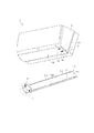
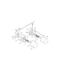
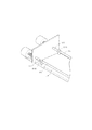
図1は、本発明の好適な実施例における空調装置を示す斜視図である。図2は、図1の領域Rを示す拡大図である。図3は、本発明の好適な実施例における空調装置の一部を示す斜視図である。以下、図1、図2及び図3を参照しながら、本発明の好適な実施例を説明する。 FIG. 1 is a perspective view showing an air conditioner in a preferred embodiment of the present invention. FIG. 2 is an enlarged view showing a region R in FIG. FIG. 3 is a perspective view showing a part of an air conditioner in a preferred embodiment of the present invention. Hereinafter, a preferred embodiment of the present invention will be described with reference to FIGS.
本実施例に係る空調装置1は、本体10と、遮蔽ユニット11と、固定板12と、第1回転部材13と、第2回転部材14と、第1駆動部材15と、第2駆動部材16と、第1弾性部材17と、第2弾性部材18とを備える。
The air conditioner 1 according to this embodiment includes a main body 10, a shielding unit 11, a fixed
本実施例において、図1に示すように、本体10は、開口部100を有する。遮蔽ユニット11は、本体10の開口部100に移動可能に設けられる。固定板12は、本体10に設けられると共に、遮蔽ユニット11の左右方向の一側に位置する。具体的には、固定板12は、本体10内に設けられると共に、遮蔽ユニット11によって遮蔽される。また、図2に示すように、第1回転部材13と第2回転部材14は、それぞれ回転自在に貫通して固定板12に設けられる。第1駆動部材15と第2駆動部材16は、それぞれ本体10に設けられると共に、第1回転部材13と第2回転部材14に接続される。第1弾性部材17は、第1駆動部材15と第1回転部材13の間に弾接され、第2弾性部材18は、第2駆動部材16と第2回転部材14の間に弾接される。
In this embodiment, as shown in FIG. 1, the main body 10 has an opening 100. The shielding unit 11 is movably provided in the opening 100 of the main body 10. The
本実施例において、図1に示すように、本体10は、さらに、第1受容孔101と、第2受容孔102と、第1弾性部103と、第2弾性部104とを有する。第1弾性部103は、第1受容孔101内に設けられ、第2弾性部104は、第2受容孔102内に設けられる。ここで、第1弾性部103と第2弾性部104は、バネであることが好ましい。しかしながら、本発明は、これに限らず、ほかの実施例において、第1弾性部103と第2弾性部104は、例えば弾性シートであってもよい。
In the present embodiment, as shown in FIG. 1, the main body 10 further includes a
本実施例において、図1に示すように、遮蔽ユニット11は、遮蔽板110と、第1軸体111と、第2軸体112とを有する。第1軸体111と第2軸体112は、それぞれ移動可能に貫通して遮蔽板110に設けられる。このうち、第1軸体111と第2軸体112は、それぞれ本体10の第1受容孔101と第2受容孔102に対応して位置することにより、第1受容孔101と第2受容孔102からそれぞれ進出する。さらに、第1軸体111は、第1受容孔101内に位置する場合に第1弾性部103に当接されるが、第2軸体112は、第2受容孔102内に位置する場合に、第2弾性部104に当接される。これにより、外力が消えると、第1軸体111と第2軸体112は、第1弾性部103と第2弾性部104の作用でそれぞれ第1受容孔101と第2受容孔102から退出することができる。
In the present embodiment, as shown in FIG. 1, the shielding unit 11 includes a
本実施例において、図1に示すように、遮蔽板110は、複数の第1突出部1101と複数の第2突出部1102を含む。第1軸体111は、移動可能に貫通して前記複数の第1突出部1101に設けられ、第2軸体112は、移動可能に貫通して前記複数の第2突出部1102に設けられる。ここで、第1突出部1101と第2突出部1102の数は、共に三つであり、遮蔽板110の両側に平均的に分布される。しかし、本発明において、第1突出部1101と第2突出部1102の数は限定されていない。また、他の実施例において、第1突出部1101と第2突出部1102を設けずに、遮蔽板110の対向する両端にそれぞれ通過孔を設けることにより、第1軸体111と第2軸体112を通過させることもできる。
In the present embodiment, as shown in FIG. 1, the shielding
本実施例において、図1に示すように、固定板12と遮蔽板110は、共に平板状であり、かつ、固定板12の配置方向は遮蔽板110の配置方向と直交状態に配置される。しかし、本発明は、これに限らず、図2に示すように、固定板12は、二つの貫通孔120と、第1位置決めユニット121と、第2位置決めユニット122とを有することもできる。ここで、二つの貫通孔120は、それぞれ第1軸体111と第2軸体112の高さに対応して設けられる。
In this embodiment, as shown in FIG. 1, the fixed
本実施例において、図2に示すように、第1位置決めユニット121は、第1エリア1211と、第2エリア1212と第3エリア1213とを有し、第2位置決めユニット122は、第1エリア1221と、第2エリア1222と、第3エリア1223とを有する。このうち、第1位置決めユニット121の第2エリア1212の高さは、第1エリア1211の高さより高く、かつ、第3エリア1213の高さより低い。第2位置決めユニット122の第2エリア1222の高さは、第1エリア1221の高さより高く、かつ、第3エリア1223の高さより低い。ここで、第1位置決めユニット121は、第2位置決めユニット122と同じ構成であることが好ましい。第1エリア1211、1221は、固定板12の表面であることが好ましい。第2エリア1212、1222と第3エリア1213、1223は、固定板12の表面から突出する突出物であることが好ましい。また、第1位置決めユニット121と第2位置決めユニット122の数は、共に二つである。しかも、二つの第1位置決めユニット121は、一つの貫通孔120を中心として対称に設けられるが、二つの第2位置決めユニット122は、もう一つの貫通孔120を中心として対称に設けられる。しかしながら、本発明は、これに限らず、他の実施例において、固定板12は、一つの第1位置決めユニット121と、一つの第2位置決めユニット122とをのみ有することも可能であり、この場合に、第1位置決めユニット121と第2位置決めユニット122が、それぞれ連続的な曲面を呈する。
In this embodiment, as shown in FIG. 2, the
本実施例において、図2に示すように、第1回転部材13は、第1貫通孔131と、第1当接部132と、第1接続部133とを有し、第2回転部材14は、第2貫通孔141と、第2当接部142と、第2接続部143と、を有する。このうち、第1回転部材13の第1接続部133と第2回転部材14の第2接続部143は、それぞれ固定板12の貫通孔120を貫通すると共に、それぞれ第1軸体111と第2軸体112の一端に当接されることができる。第1回転部材13の第1当接部132は、固定板12の第1位置決めユニット121に当接され、第2回転部材14の第2当接部142は、固定板12の第2位置決めユニット122に当接される。なお、ここで、第1回転部材13と第2回転部材14は共にT字形であるが、本発明はこれに限るものではない。
In the present embodiment, as shown in FIG. 2, the first rotating
第1回転部材13の回転過程を例にすると、第1回転部材13が回転する時、第1当接部132は、固定板12の第1位置決めユニット121上の位置を変更することにより、第1回転部材13が貫通孔120を貫通する長さを変化させる。本実施例において、第1当接部132が第1位置決めユニット121の第1エリア1211と第2エリア1212内に当接される時、第1回転部材13は、遮蔽ユニット11の前後方向の一側部に固定されることができる。具体的には、図3に示すように、第1接続部133は、遮蔽板110の第1突出部1101に進入して、第1突出部1101内に位置する第1軸体111を押し動かすことにより、第1軸体111の左右方向の一端に当接される。これにより、第1軸体111の他端が第1接続部133の押圧により、本体10の第1受容孔101に進入して、第1弾性部103に当接される。第1当接部132が第1位置決めユニット121の第3エリア1213内に当接されると、第1接続部133が第1突出部1101から退出し、第1軸体111も第1弾性部103の弾力作用によって、第1受容孔101から、本体10からの離脱を可能にする。
Taking the rotation process of the first rotating
このうち、第1当接部132と第2当接部142を、それぞれ第1位置決めユニット121と第2位置決めユニット122との三つエリア内でスムーズに移動させるために、第1位置決めユニット121と第2位置決めユニット122の三つのエリアの間を斜面で接続し、かつ、第1当接部132と第1位置決めユニット121との接触面及び、第2当接部142と第2位置決めユニット122との接触面を共に円弧面にする。しかし、本発明は、これに限るものではない。
Among these, in order to smoothly move the
本実施例において、図2に示すように、第1駆動部材15は、第1ロッド体151を有し、第2駆動部材16は、第2ロッド体161を有する。第1弾性部材17は、第1ロッド体151に取り付けられ、かつ、第1ロッド体151の一端が第1回転部材13の第1貫通孔131の中に位置する。これにより、第1弾性部材17が第1回転部材13と第1駆動部材15との間に弾接される。第2弾性部材18は、第2ロッド体161に取り付けられ、かつ、第2ロッド体161の一端が第2回転部材14の第2貫通孔141中に位置する。これにより、第2弾性部材18が第2回転部材14と第2駆動部材16との間に弾接される。
In the present embodiment, as shown in FIG. 2, the
また、本実施例において、第1駆動部材15と第2駆動部材16は、共に電動機である。これにより、第1駆動部材15は第1回転部材13を駆動回転させ、第2駆動部材16は、第2回転部材14を駆動回転させる。第1回転部材13が回転する際に、第1弾性部材17が弾性変形することにより、第1回転部材13の第1当接部132を第1エリア1211、第2エリア1212または第3エリア1213に当接させる。同様に、第2回転部材14が回転する際に、第2弾性部材18が弾性変形することにより、第2回転部材14の第2当接部142を第1エリア1221、第2エリア1222または第3エリア1223に当接させる。ここで、第1弾性部材17と第2弾性部材18は、共にバネであるが、本発明は、これに限らず、他の実施例において、第1駆動部材15と第2駆動部材16は、他の駆動裝置であってもよい。また、第1弾性部材17と第2弾性部材18は、弾性シートのような他の弾性素子でもよい。
In the present embodiment, both the
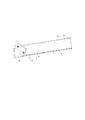
図4は、本発明の好適な実施例における空調装置の部分動作を示す図である。以下、図1〜図4を参照しながら、空調装置1の作動過程を具体的に説明する。 FIG. 4 is a diagram showing a partial operation of the air conditioner in a preferred embodiment of the present invention. Hereinafter, the operation process of the air conditioner 1 will be described in detail with reference to FIGS.
本実施例において、第1駆動部材15が、第1当接部132が第1位置決めユニット121の第2エリア1212内に当接するまで、第1回転部材13を駆動回転させ、かつ、第2駆動部材16が、第2当接部142が第2位置決めユニット122の第2エリア1222内に当接するまで、第2回転部材14を駆動回転させる時、第1回転部材13と第2回転部材14は、それぞれ遮蔽ユニット11の前後方向の両側部に固定されると共に、遮蔽ユニット11の開口部100を遮蔽する。この時、空調装置1は、非送風状態にある。
In the present embodiment, the first driving
具体的には、この時、第1回転部材13の第1接続部133は、第1軸体111の一端に当接されると共に、第1軸体111の他端を押し動かして第1受容孔101に進入しながら第1弾性部103に当接される。第2回転部材14の第2接続部143は、第2軸体112の一端に当接されると共に、第2軸体112の他端を押し動かして第2受容孔102に進入しながら第2弾性部104に当接される。このようにして、第1回転部材13と第2回転部材14は、遮蔽ユニット11を本体10に固定する。
Specifically, at this time, the first connecting
本実施例において、第1駆動部材15は、第1当接部132が第1位置決めユニット121の第1エリア1211内に当接するまで、第1回転部材13を駆動回転させ、かつ、第2駆動部材16が、第2当接部142が第2位置決めユニット122の第3エリア1223内に当接するまで、第2回転部材14を駆動回転させる時、第2回転部材14は、遮蔽ユニット11から離脱し、第1回転部材13は、遮蔽ユニット11の前後方向の一側部を固定すると共に、第1方向D1に沿って遮蔽ユニット11を連動回転させ、本体10の開口部100から露出させる。この時、空調装置1は、暖房運転モードにある。すなわち、図4に示すように。空調装置1は、第1方向D1に沿って、遮蔽ユニット11の遮蔽板110を打開し、開口部100から露出し、温風を送出する。
In the present embodiment, the first driving
具体的には、この時、第1回転部材13の第1接続部133は、第1軸体111の一端に当接されると共に、第1軸体111の他端を押し動かして第1受容孔101に進入させながら第1弾性部103に当接される。このうち、第1位置決めユニット121の第2エリア1212の高さは、第1エリア1211の高さより高いため、この時の、第1軸体111が第1回転部材13によって移動される距離は、空調装置1が非送風状態にあるときの、第1軸体111が第1回転部材13によって移動される距離より大きい。第1回転部材13と第1軸体111と本体10は、より緊密に固定される。これにより、遮蔽ユニット11の遮蔽板110は、第1駆動部材15の作用で第1軸体111を軸として回転する。
Specifically, at this time, the first connecting
また、第2回転部材14の第2当接部142が第2位置決めユニット122の第2エリア1222から第3エリア1223へ移動して当接されるため、第2回転部材14の第2接続部143は、第2軸体112の一端から離脱することになる。同時に、第2軸体112も、第2受容孔102の第2弾性部104の作用で第2受容孔102から離脱することになる。言い換えれば、遮蔽ユニット11の第2軸体112は、本体10から離脱することになる。
In addition, since the second contact portion 142 of the second rotating
本実施例において、第1回転部材13が第1方向D1に沿って遮蔽ユニット11を連動回転させる範囲は、0〜90度である。これにより、空調装置1から送出された温風が下へ吹くため、冷風が排除されることになる。
In the present embodiment, the range in which the first rotating
本実施例において、第1駆動部材15が、第1当接部132が第1位置決めユニット121の第3エリア1213内に当接するまで、第1回転部材13を駆動回転させ、かつ、第2駆動部材16が、第2当接部142が第2位置決めユニット122の第1エリア1221内に当接するまで、第2回転部材14を駆動回転させる時、第1回転部材13は、遮蔽ユニット11から離脱し、第2回転部材14は、遮蔽ユニット11の前後方向の他側部に固定されると共に、第2方向D2に沿って遮蔽ユニット11を連動回転させ本体10の開口部100から露出させる。この時、空調装置1は、冷房運転モードにある。すなわち、空調装置1は、第2方向D2に沿って、打開遮蔽ユニット11の遮蔽板110を開き、開口部100から露出して冷風を送出する。このうち、第1方向D1と第2方向D2は、互いに逆方向である。
In the present embodiment, the first driving
具体的には、この時、第2回転部材14の第2接続部143は、第2軸体112の一端に当接されると共に、第2軸体112の他端を押し動かして第2受容孔102に進入させながら、第2弾性部104に当接される。このうち、第2位置決めユニット122の第2エリア1222の高さは、第1エリア1221の高さより高いために、この時の、第2軸体112が第2回転部材14によって移動される距離は、空調装置1が非送風状態にあるときの、第2軸体112が第2回転部材14によって移動される距離より大きい。第2回転部材14と第2軸体112と本体10は、より緊密に固定される。これにより、遮蔽ユニット11の遮蔽板110は、第2駆動部材16の作用で、第2軸体112を軸として回転する。
Specifically, at this time, the second connecting
また、第1回転部材13の第1当接部132が第1位置決めユニット121の第2エリア1212から第3エリア1213へ移動して当接されるため、第1回転部材13の第1接続部133は、第1軸体111の一端から離脱することになる。同時に、第1軸体111も、第1受容孔101の第1弾性部103の作用で、第1受容孔101から離脱することになる。言い換えれば、遮蔽ユニット11の第1軸体111は、本体10から離脱することになる。
In addition, since the
本実施例において、第2回転部材14が第2方向D2に沿って、遮蔽ユニット11を連動回転させる範囲は、0〜45度である。これにより、空調装置1から送出された冷風が上へ吹くため、温風が排除されることになる。
In the present embodiment, the range in which the second rotating
上述したように、本発明の好適な実施例にける空調装置は、第1駆動部材と、第1回転部材と、第1弾性部材と、第1軸体と、第1受容孔とが、互いに対応し、第2駆動部材と、第2回転部材と、第2弾性部材と、第2軸体と、第2受容孔とが、互いに対応する。これにより、遮蔽ユニットの遮蔽板は、第1軸体に沿って回転することにより暖房運転を実現し、さらに、第2軸体に沿って回転することにより冷房運転を実現する。このようにして、遮蔽板は、送風過程中に常に一方方向に送風するため、遮蔽ユニットが送風過程中における漏洩を回避することができる。 As described above, the air conditioner according to a preferred embodiment of the present invention includes the first driving member, the first rotating member, the first elastic member, the first shaft body, and the first receiving hole. Correspondingly, the second driving member, the second rotating member, the second elastic member, the second shaft body, and the second receiving hole correspond to each other. Thereby, the shielding plate of the shielding unit realizes the heating operation by rotating along the first shaft body, and further realizes the cooling operation by rotating along the second shaft body. Thus, since the shielding plate always blows air in one direction during the blowing process, the shielding unit can avoid leakage during the blowing process.
また、本発明の好適な実施例における空調装置は、その第1駆動部材と第2駆動部材が、それぞれ第1方向または第2方向に沿って、遮蔽ユニットを連動回転させることにより、空調装置が暖房運転モード時と冷房運転モード時に、異なる送風方向と送風角度を有することができる。このうち、空調装置が暖房運転モード時の送風角度範囲は、0〜90度で、冷房運転モード時の送風角度は、0〜45度である。したがって、空調装置の暖房運転モード時と冷房運転モード時の効率を向上することができる。 In the air conditioner according to a preferred embodiment of the present invention, the first drive member and the second drive member rotate the shielding unit in conjunction with each other along the first direction or the second direction, respectively. It is possible to have different blowing directions and blowing angles in the heating operation mode and the cooling operation mode. Among these, the ventilation angle range when the air conditioner is in the heating operation mode is 0 to 90 degrees, and the ventilation angle when the cooling operation mode is 0 to 45 degrees. Therefore, the efficiency of the air conditioner in the heating operation mode and the cooling operation mode can be improved.
以上、本発明の実施例を図面を参照して詳述してきたが、具体的な構成は、これらの実施例に限られるものではなく、本発明の要旨を逸脱しない範囲の設計変更などがあっても、本発明に含まれる。 As described above, the embodiments of the present invention have been described in detail with reference to the drawings. However, the specific configuration is not limited to these embodiments, and there are design changes and the like without departing from the gist of the present invention. However, it is included in the present invention.
本発明は以上詳細に説明したように、二つの軸体を切り替えることにより吹出口の調節を行うことにより、温風や冷風が漏洩するのを防止できる空調装置として好適に用いられるものである。 As described in detail above, the present invention is suitably used as an air conditioner that can prevent leakage of hot air or cold air by adjusting the air outlet by switching two shaft bodies.
1 空調装置
10 本体
11 遮蔽ユニット
12 固定板
13 第1回転部材
14 第2回転部材
15 第1駆動部材
16 第2駆動部材
17 第1弾性部材
18 第2弾性部材
100 開口部
101 第1受容孔
102 第2受容孔
103 第1弾性部
104 第2弾性部
110 遮蔽板
111 第1軸体
112 第2軸体
120 貫通孔
121 第1位置決めユニット
122 第2位置決めユニット
131 第1貫通孔
132 第1当接部
133 第1接続部
141 第2貫通孔
142 第2当接部
143 第2接続部
151 第1ロッド体
161 第2ロッド体
1101 第1突出部
1102 第2突出部
1211、1221 第1エリア
1212、1222 第2エリア
1213、1223 第3エリア
D1 第1方向
D2 第2方向
R 領域
DESCRIPTION OF SYMBOLS 1 Air conditioner 10 Main body 11
Claims (10)
前記本体の前記開口部に移動可能に設けられる遮蔽ユニットと、
前記本体に設けられ、かつ、前記遮蔽ユニットの左右方向の一側に位置して設けられ、第1位置決めユニットと、第2位置決めユニットとを有し、前記第1位置決めユニットと前記第2位置決めユニットは、いずれも第1エリアと、第2エリアと、第3エリアとを含み、前記第2エリアの高さが、前記第1エリアの高さより高く、かつ、前記第3エリアの高さより低い固定板と、
第1当接部を有し、回転自在に貫通して前記固定板に設けられる第1回転部材と、
前記本体に設けられ、かつ、前記第1回転部材に接続されることにより前記第1回転部材を駆動して回転させる第1駆動部材と、
前記第1駆動部材と前記第1回転部材との間に当接され、前記第1回転部材が回転する際に弾性変形することにより前記第1当接部を前記第1エリア、前記第2エリア及び前記第3エリアのいずれかに当接させる第1弾性部材と、
第2当接部を有し、回転自在に貫通して前記固定板に設けられる第2回転部材と、
前記本体に設けられ、前記第2回転部材に接続されることにより前記第2回転部材を駆動して回転させる第2駆動部材と、
前記第2駆動部材と前記第2回転部材との間に当接され、前記第2回転部材が回転する際に弾性変形することにより、前記第2当接部を前記第1エリア、前記第2エリア及び前記第3エリアのいずれかに当接させる第2弾性部材と、を備える空調装置であって、
前記第1当接部が前記第1位置決めユニットの前記第2エリア内に当接され、かつ、前記第2当接部が前記第2位置決めユニットの前記第2エリア内に当接される際には、前記第1回転部材と前記第2回転部材は、それぞれ前記遮蔽ユニットの前後方向の両側部に固定されると共に、前記遮蔽ユニットが前記開口部を遮蔽し、
前記第1当接部が前記第1位置決めユニットの前記第1エリア内に当接され、かつ、前記第2当接部が前記第2位置決めユニットの前記第3エリア内に当接される際には、前記第2回転部材が前記遮蔽ユニットから離脱し、前記第1回転部材が前記遮蔽ユニットの前後方向の一側部に固定されると共に、第1方向に沿って前記遮蔽ユニットを連動回転させ、前記開口部を露出させ、
前記第1当接部が前記第1位置決めユニットの前記第3エリア内に当接され、かつ、前記第2当接部が前記第2位置決めユニットの前記第1エリア内に当接される際に、前記第1回転部材が前記遮蔽ユニットから離脱し、前記第2回転部材が前記遮蔽ユニットの前後方向の他側部に固定されると共に、第2方向に沿って前記遮蔽ユニットを連動回転させ前記開口部を露出させる、ことを特徴とする空調装置。 A body having an opening;
A shielding unit movably provided in the opening of the main body;
Provided in the main body, and is provided located at one side in the lateral direction of the blocking unit, and a first positioning unit, and a second positioning unit, wherein the first positioning unit and the second positioning unit Includes a first area, a second area, and a third area, and the height of the second area is higher than the height of the first area and lower than the height of the third area. The board,
A first rotating member having a first abutment portion and rotatably penetratingly provided on the fixed plate;
A first drive member provided in the main body and connected to the first rotation member to drive and rotate the first rotation member;
The first abutting portion is abutted between the first driving member and the first rotating member, and is elastically deformed when the first rotating member rotates, thereby causing the first abutting portion to move to the first area and the second area. And a first elastic member to be brought into contact with any one of the third areas,
A second rotating member having a second abutting portion and penetrating rotatably and provided on the fixed plate;
A second drive member provided on the main body and connected to the second rotation member to drive and rotate the second rotation member;
The second abutting portion is abutted between the second driving member and the second rotating member, and elastically deforms when the second rotating member rotates, thereby causing the second abutting portion to move to the first area and the second rotating member. An air conditioner comprising: a second elastic member that is brought into contact with either the area or the third area,
It said first contact portion is brought into contact with the second area of the first positioning unit, and, when the second abutment portion is brought into contact with the second area of the second positioning unit , the first rotary member and the second rotary member is fixed to both sides of the longitudinal direction of each of the shielding unit, wherein the blocking unit is blocking the opening,
It said first contact portion is brought into contact with the first area of the first positioning unit, and, when the second abutment portion is brought into contact with the third area of the second positioning unit , the second rotating member disengaged from the blocking unit, together with the first rotary member is fixed in the longitudinal direction of the one side of the blocking unit, in conjunction rotating the blocking unit along a first direction Exposing the opening;
When the first contact portion is in contact with the third area of the first positioning unit and the second contact portion is in contact with the first area of the second positioning unit. The first rotating member is detached from the shielding unit, the second rotating member is fixed to the other side of the shielding unit in the front-rear direction , and the shielding unit is rotated in conjunction with the second direction. An air conditioner that exposes an opening.
Applications Claiming Priority (2)
| Application Number | Priority Date | Filing Date | Title |
|---|---|---|---|
| CN2011100329119A CN102620400B (en) | 2011-01-30 | 2011-01-30 | Air conditioning device |
| CN201110032911.9 | 2011-01-30 |
Publications (2)
| Publication Number | Publication Date |
|---|---|
| JP2012159283A JP2012159283A (en) | 2012-08-23 |
| JP5284497B2 true JP5284497B2 (en) | 2013-09-11 |
Family
ID=46560484
Family Applications (1)
| Application Number | Title | Priority Date | Filing Date |
|---|---|---|---|
| JP2012011453A Active JP5284497B2 (en) | 2011-01-30 | 2012-01-23 | Air conditioner |
Country Status (4)
| Country | Link |
|---|---|
| JP (1) | JP5284497B2 (en) |
| KR (1) | KR101285970B1 (en) |
| CN (1) | CN102620400B (en) |
| TW (1) | TWI429860B (en) |
Families Citing this family (3)
| Publication number | Priority date | Publication date | Assignee | Title |
|---|---|---|---|---|
| TW201430293A (en) * | 2013-01-21 | 2014-08-01 | Yong Fu Internat Co Ltd | Air outlet and air return port device |
| US10619648B2 (en) | 2017-02-10 | 2020-04-14 | Samsung Electronics Co., Ltd. | Air conditioner |
| CN116123603A (en) * | 2021-11-15 | 2023-05-16 | 宁波奥克斯电气股份有限公司 | Air guide device and air conditioner |
Family Cites Families (11)
| Publication number | Priority date | Publication date | Assignee | Title |
|---|---|---|---|---|
| MXPA02005949A (en) | 1999-12-17 | 2003-01-28 | Du Pont | Continuous process for the preparation of polytrimethylene ether glycol. |
| JP3923876B2 (en) | 2002-09-11 | 2007-06-06 | シャープ株式会社 | Air conditioner |
| KR100814023B1 (en) | 2007-02-21 | 2008-03-17 | 삼성전자주식회사 | Air conditioner |
| JP5034707B2 (en) * | 2007-06-20 | 2012-09-26 | ダイキン工業株式会社 | Air conditioner |
| JP4237238B1 (en) * | 2007-09-07 | 2009-03-11 | シャープ株式会社 | Air conditioner |
| JP2009074757A (en) * | 2007-09-21 | 2009-04-09 | Fujitsu General Ltd | Air conditioner |
| JP4382860B1 (en) * | 2008-07-02 | 2009-12-16 | シャープ株式会社 | Air conditioner |
| CN201262459Y (en) * | 2008-07-29 | 2009-06-24 | 张领强 | Wind direction converter of air conditioner |
| CN201335499Y (en) * | 2008-12-03 | 2009-10-28 | 广东美的电器股份有限公司 | Air-out panel of air pipe type air conditioner indoor machine |
| KR20100074363A (en) * | 2008-12-24 | 2010-07-02 | 최창호 | Ventilating hole with fire damper |
| JP5192526B2 (en) * | 2010-09-29 | 2013-05-08 | シャープ株式会社 | Air conditioner |
-
2011
- 2011-01-30 CN CN2011100329119A patent/CN102620400B/en active Active
- 2011-10-11 TW TW100136802A patent/TWI429860B/en active
- 2011-12-14 KR KR1020110134194A patent/KR101285970B1/en active Active
-
2012
- 2012-01-23 JP JP2012011453A patent/JP5284497B2/en active Active
Also Published As
| Publication number | Publication date |
|---|---|
| TWI429860B (en) | 2014-03-11 |
| TW201231887A (en) | 2012-08-01 |
| CN102620400A (en) | 2012-08-01 |
| CN102620400B (en) | 2013-12-11 |
| JP2012159283A (en) | 2012-08-23 |
| KR101285970B1 (en) | 2013-07-12 |
| KR20120088520A (en) | 2012-08-08 |
Similar Documents
| Publication | Publication Date | Title |
|---|---|---|
| US6415622B2 (en) | Air outlet opening apparatus for air conditioners | |
| JP5284497B2 (en) | Air conditioner | |
| JP5284498B2 (en) | Air conditioner | |
| JP2012114379A (en) | Air cooling mechanism | |
| JP6716007B2 (en) | Air conditioner | |
| CN113178135B (en) | display device | |
| CN108088059B (en) | Air deflector assembly, air conditioning indoor unit and air conditioner | |
| WO2017124866A1 (en) | Air conditioner and indoor unit thereof | |
| CN105765315A (en) | Indoor unit | |
| JP2009299991A (en) | Wind direction changing device and air conditioning device comprising the same | |
| AU2014355759B2 (en) | Indoor unit | |
| JP2009299992A (en) | Indoor unit of air conditioning device | |
| JP2007205584A (en) | Air conditioner | |
| JP5796313B2 (en) | Wind direction changing device and air conditioner equipped with the same | |
| JP5487582B2 (en) | Rack equipment | |
| CN214791477U (en) | Indoor unit of air conditioner | |
| CN204438463U (en) | The air-out component of indoor apparatus of air conditioner and there is its indoor apparatus of air conditioner | |
| KR20140059562A (en) | Air venting apparatus of an automobile | |
| JP2012052725A (en) | Air conditioner | |
| CN205980220U (en) | Indoor unit | |
| JP4650081B2 (en) | Air conditioner | |
| JP6756313B2 (en) | Shutter device | |
| JP4675752B2 (en) | Air conditioner | |
| JP2010117105A (en) | Indoor unit for air conditioning | |
| JP6200547B2 (en) | Wind direction changing device and air conditioner having the same |
Legal Events
| Date | Code | Title | Description |
|---|---|---|---|
| A131 | Notification of reasons for refusal |
Free format text: JAPANESE INTERMEDIATE CODE: A131 Effective date: 20130115 |
|
| A521 | Request for written amendment filed |
Free format text: JAPANESE INTERMEDIATE CODE: A523 Effective date: 20130410 |
|
| TRDD | Decision of grant or rejection written | ||
| A01 | Written decision to grant a patent or to grant a registration (utility model) |
Free format text: JAPANESE INTERMEDIATE CODE: A01 Effective date: 20130514 |
|
| A61 | First payment of annual fees (during grant procedure) |
Free format text: JAPANESE INTERMEDIATE CODE: A61 Effective date: 20130529 |
|
| R150 | Certificate of patent or registration of utility model |
Ref document number: 5284497 Country of ref document: JP Free format text: JAPANESE INTERMEDIATE CODE: R150 |
|
| R250 | Receipt of annual fees |
Free format text: JAPANESE INTERMEDIATE CODE: R250 |
|
| R250 | Receipt of annual fees |
Free format text: JAPANESE INTERMEDIATE CODE: R250 |
|
| R250 | Receipt of annual fees |
Free format text: JAPANESE INTERMEDIATE CODE: R250 |