JP5282012B2 - Braking device with safety braking function - Google Patents
Braking device with safety braking function Download PDFInfo
- Publication number
- JP5282012B2 JP5282012B2 JP2009261033A JP2009261033A JP5282012B2 JP 5282012 B2 JP5282012 B2 JP 5282012B2 JP 2009261033 A JP2009261033 A JP 2009261033A JP 2009261033 A JP2009261033 A JP 2009261033A JP 5282012 B2 JP5282012 B2 JP 5282012B2
- Authority
- JP
- Japan
- Prior art keywords
- wedge
- sub
- braking
- wheel disc
- caliper
- Prior art date
- Legal status (The legal status is an assumption and is not a legal conclusion. Google has not performed a legal analysis and makes no representation as to the accuracy of the status listed.)
- Expired - Fee Related
Links
Images


Classifications
-
- F—MECHANICAL ENGINEERING; LIGHTING; HEATING; WEAPONS; BLASTING
- F16—ENGINEERING ELEMENTS AND UNITS; GENERAL MEASURES FOR PRODUCING AND MAINTAINING EFFECTIVE FUNCTIONING OF MACHINES OR INSTALLATIONS; THERMAL INSULATION IN GENERAL
- F16D—COUPLINGS FOR TRANSMITTING ROTATION; CLUTCHES; BRAKES
- F16D65/00—Parts or details
- F16D65/14—Actuating mechanisms for brakes; Means for initiating operation at a predetermined position
-
- B—PERFORMING OPERATIONS; TRANSPORTING
- B60—VEHICLES IN GENERAL
- B60T—VEHICLE BRAKE CONTROL SYSTEMS OR PARTS THEREOF; BRAKE CONTROL SYSTEMS OR PARTS THEREOF, IN GENERAL; ARRANGEMENT OF BRAKING ELEMENTS ON VEHICLES IN GENERAL; PORTABLE DEVICES FOR PREVENTING UNWANTED MOVEMENT OF VEHICLES; VEHICLE MODIFICATIONS TO FACILITATE COOLING OF BRAKES
- B60T8/00—Arrangements for adjusting wheel-braking force to meet varying vehicular or ground-surface conditions, e.g. limiting or varying distribution of braking force
- B60T8/32—Arrangements for adjusting wheel-braking force to meet varying vehicular or ground-surface conditions, e.g. limiting or varying distribution of braking force responsive to a speed condition, e.g. acceleration or deceleration
- B60T8/34—Arrangements for adjusting wheel-braking force to meet varying vehicular or ground-surface conditions, e.g. limiting or varying distribution of braking force responsive to a speed condition, e.g. acceleration or deceleration having a fluid pressure regulator responsive to a speed condition
- B60T8/343—Systems characterised by their lay-out
- B60T8/344—Hydraulic systems
- B60T8/345—Hydraulic systems having more than one brake circuit per wheel
-
- B—PERFORMING OPERATIONS; TRANSPORTING
- B60—VEHICLES IN GENERAL
- B60T—VEHICLE BRAKE CONTROL SYSTEMS OR PARTS THEREOF; BRAKE CONTROL SYSTEMS OR PARTS THEREOF, IN GENERAL; ARRANGEMENT OF BRAKING ELEMENTS ON VEHICLES IN GENERAL; PORTABLE DEVICES FOR PREVENTING UNWANTED MOVEMENT OF VEHICLES; VEHICLE MODIFICATIONS TO FACILITATE COOLING OF BRAKES
- B60T13/00—Transmitting braking action from initiating means to ultimate brake actuator with power assistance or drive; Brake systems incorporating such transmitting means, e.g. air-pressure brake systems
- B60T13/02—Transmitting braking action from initiating means to ultimate brake actuator with power assistance or drive; Brake systems incorporating such transmitting means, e.g. air-pressure brake systems with mechanical assistance or drive
-
- B—PERFORMING OPERATIONS; TRANSPORTING
- B60—VEHICLES IN GENERAL
- B60T—VEHICLE BRAKE CONTROL SYSTEMS OR PARTS THEREOF; BRAKE CONTROL SYSTEMS OR PARTS THEREOF, IN GENERAL; ARRANGEMENT OF BRAKING ELEMENTS ON VEHICLES IN GENERAL; PORTABLE DEVICES FOR PREVENTING UNWANTED MOVEMENT OF VEHICLES; VEHICLE MODIFICATIONS TO FACILITATE COOLING OF BRAKES
- B60T13/00—Transmitting braking action from initiating means to ultimate brake actuator with power assistance or drive; Brake systems incorporating such transmitting means, e.g. air-pressure brake systems
- B60T13/74—Transmitting braking action from initiating means to ultimate brake actuator with power assistance or drive; Brake systems incorporating such transmitting means, e.g. air-pressure brake systems with electrical assistance or drive
- B60T13/741—Transmitting braking action from initiating means to ultimate brake actuator with power assistance or drive; Brake systems incorporating such transmitting means, e.g. air-pressure brake systems with electrical assistance or drive acting on an ultimate actuator
-
- B—PERFORMING OPERATIONS; TRANSPORTING
- B60—VEHICLES IN GENERAL
- B60T—VEHICLE BRAKE CONTROL SYSTEMS OR PARTS THEREOF; BRAKE CONTROL SYSTEMS OR PARTS THEREOF, IN GENERAL; ARRANGEMENT OF BRAKING ELEMENTS ON VEHICLES IN GENERAL; PORTABLE DEVICES FOR PREVENTING UNWANTED MOVEMENT OF VEHICLES; VEHICLE MODIFICATIONS TO FACILITATE COOLING OF BRAKES
- B60T17/00—Component parts, details, or accessories of power brake systems not covered by groups B60T8/00, B60T13/00 or B60T15/00, or presenting other characteristic features
- B60T17/18—Safety devices; Monitoring
-
- F—MECHANICAL ENGINEERING; LIGHTING; HEATING; WEAPONS; BLASTING
- F16—ENGINEERING ELEMENTS AND UNITS; GENERAL MEASURES FOR PRODUCING AND MAINTAINING EFFECTIVE FUNCTIONING OF MACHINES OR INSTALLATIONS; THERMAL INSULATION IN GENERAL
- F16D—COUPLINGS FOR TRANSMITTING ROTATION; CLUTCHES; BRAKES
- F16D65/00—Parts or details
- F16D65/14—Actuating mechanisms for brakes; Means for initiating operation at a predetermined position
- F16D65/16—Actuating mechanisms for brakes; Means for initiating operation at a predetermined position arranged in or on the brake
- F16D65/18—Actuating mechanisms for brakes; Means for initiating operation at a predetermined position arranged in or on the brake adapted for drawing members together, e.g. for disc brakes
-
- B—PERFORMING OPERATIONS; TRANSPORTING
- B60—VEHICLES IN GENERAL
- B60T—VEHICLE BRAKE CONTROL SYSTEMS OR PARTS THEREOF; BRAKE CONTROL SYSTEMS OR PARTS THEREOF, IN GENERAL; ARRANGEMENT OF BRAKING ELEMENTS ON VEHICLES IN GENERAL; PORTABLE DEVICES FOR PREVENTING UNWANTED MOVEMENT OF VEHICLES; VEHICLE MODIFICATIONS TO FACILITATE COOLING OF BRAKES
- B60T2270/00—Further aspects of brake control systems not otherwise provided for
- B60T2270/83—Control features of electronic wedge brake [EWB]
-
- F—MECHANICAL ENGINEERING; LIGHTING; HEATING; WEAPONS; BLASTING
- F16—ENGINEERING ELEMENTS AND UNITS; GENERAL MEASURES FOR PRODUCING AND MAINTAINING EFFECTIVE FUNCTIONING OF MACHINES OR INSTALLATIONS; THERMAL INSULATION IN GENERAL
- F16D—COUPLINGS FOR TRANSMITTING ROTATION; CLUTCHES; BRAKES
- F16D2121/00—Type of actuator operation force
- F16D2121/18—Electric or magnetic
- F16D2121/20—Electric or magnetic using electromagnets
- F16D2121/22—Electric or magnetic using electromagnets for releasing a normally applied brake
-
- F—MECHANICAL ENGINEERING; LIGHTING; HEATING; WEAPONS; BLASTING
- F16—ENGINEERING ELEMENTS AND UNITS; GENERAL MEASURES FOR PRODUCING AND MAINTAINING EFFECTIVE FUNCTIONING OF MACHINES OR INSTALLATIONS; THERMAL INSULATION IN GENERAL
- F16D—COUPLINGS FOR TRANSMITTING ROTATION; CLUTCHES; BRAKES
- F16D2121/00—Type of actuator operation force
- F16D2121/18—Electric or magnetic
- F16D2121/24—Electric or magnetic using motors
-
- F—MECHANICAL ENGINEERING; LIGHTING; HEATING; WEAPONS; BLASTING
- F16—ENGINEERING ELEMENTS AND UNITS; GENERAL MEASURES FOR PRODUCING AND MAINTAINING EFFECTIVE FUNCTIONING OF MACHINES OR INSTALLATIONS; THERMAL INSULATION IN GENERAL
- F16D—COUPLINGS FOR TRANSMITTING ROTATION; CLUTCHES; BRAKES
- F16D2123/00—Multiple operation forces
-
- F—MECHANICAL ENGINEERING; LIGHTING; HEATING; WEAPONS; BLASTING
- F16—ENGINEERING ELEMENTS AND UNITS; GENERAL MEASURES FOR PRODUCING AND MAINTAINING EFFECTIVE FUNCTIONING OF MACHINES OR INSTALLATIONS; THERMAL INSULATION IN GENERAL
- F16D—COUPLINGS FOR TRANSMITTING ROTATION; CLUTCHES; BRAKES
- F16D2125/00—Components of actuators
- F16D2125/18—Mechanical mechanisms
- F16D2125/20—Mechanical mechanisms converting rotation to linear movement or vice versa
- F16D2125/34—Mechanical mechanisms converting rotation to linear movement or vice versa acting in the direction of the axis of rotation
- F16D2125/40—Screw-and-nut
-
- F—MECHANICAL ENGINEERING; LIGHTING; HEATING; WEAPONS; BLASTING
- F16—ENGINEERING ELEMENTS AND UNITS; GENERAL MEASURES FOR PRODUCING AND MAINTAINING EFFECTIVE FUNCTIONING OF MACHINES OR INSTALLATIONS; THERMAL INSULATION IN GENERAL
- F16D—COUPLINGS FOR TRANSMITTING ROTATION; CLUTCHES; BRAKES
- F16D2127/00—Auxiliary mechanisms
- F16D2127/08—Self-amplifying or de-amplifying mechanisms
- F16D2127/10—Self-amplifying or de-amplifying mechanisms having wedging elements
Landscapes
- Engineering & Computer Science (AREA)
- Mechanical Engineering (AREA)
- Transportation (AREA)
- General Engineering & Computer Science (AREA)
- Physics & Mathematics (AREA)
- Fluid Mechanics (AREA)
- Braking Arrangements (AREA)
- Braking Systems And Boosters (AREA)
- Regulating Braking Force (AREA)
- Valves And Accessory Devices For Braking Systems (AREA)
Description
本発明は制動装置に関し、より詳しくは、二重に構成された制動装置を利用して安全制動機能を実現する制動装置に関する。 The present invention relates to a braking device, and more particularly to a braking device that realizes a safety braking function using a double-structured braking device.
一般的に、油圧式ブレーキは制動時に油圧を利用してパッドを強くディスク側に押す方式で実現される。
このような油圧式ブレーキは、複雑な構成と油圧使用による制動性能の信頼性と安定性の強化にある程度限界性があり、そのため、油圧式ブレーキが有することができない構成の単純さを招き、制動性能の信頼性を強化できる電動制動装置であるEMB(Electro Mechanical Brake)が適用される傾向である。
In general, a hydraulic brake is realized by using a hydraulic pressure during braking to push the pad strongly toward the disk.
Such hydraulic brakes have some limitations in enhancing the reliability and stability of the braking performance due to the complicated configuration and use of hydraulic pressure, which leads to the simplicity of the configuration that the hydraulic brake cannot have, There is a tendency that EMB (Electro Mechanical Break) which is an electric braking device capable of enhancing the reliability of performance is applied.
このようなEMBはモータ動力を直接に直進移動力に切り換えて制動を実現する方式である。
このようにモータ動力を用いるEMB方式としてEWB(Electro Wedge Brake)もあって、これは、制動時にアクチュエータを介して作動するウェッジ組立体を利用してブレーキパッドをディスク側に加圧することによって摩擦させることで、入力を倍力するウェッジ作用で制動を実現する方式である。
このようなEMBとEWBを通常BBW(Brake By Wire)技術と称する。
Such an EMB is a system that realizes braking by directly switching motor power to linear movement force.
There is also an EWB (Electro Wedge Break) as an EMB system that uses motor power as described above, and this makes friction by pressurizing the brake pad to the disk side using a wedge assembly that operates via an actuator during braking. Thus, braking is realized by a wedge action that boosts the input.
Such EMB and EWB are generally referred to as BBW (Brake By Wire) technology.
しかし、このような電動制動装置は12Vで実現しなければならず、電子信号と電気装置で制動を行うため、FR(Failure Rate)が油圧制動方式に比べて高く増加する根本的な限界を有する。 However, such an electric braking device has to be realized at 12V, and since braking is performed with an electronic signal and an electric device, there is a fundamental limit that FR (Failure Rate) increases higher than the hydraulic braking method. .
そのため、FR(Failure Rate)を安定的な油圧制動方式のように低くするために様々な方法が開発され、その一例としてEWBやEMBを制御する制御ロジックとこれを反映する回路を構成し、F−S(Fail−Safe)を実現してFR(Failure Rate)を低くするが、このような方式は動力源であるモータの故障(Fail)状況において、機構的に制動力を発生させる装置を備えないことによって安全性が低下し、このような安定性の低下によって実車適用にはばかられる原因を提供する。 For this reason, various methods have been developed to lower the FR (Failure Rate) as in a stable hydraulic braking system. As an example, a control logic that controls the EWB and EMB and a circuit that reflects the control logic are configured. -S (Fail-Safe) is realized and FR (Failure Rate) is lowered, but such a system is provided with a device that mechanically generates a braking force in a failure state of a motor that is a power source. The lack of safety reduces the safety, and such a reduction in stability provides a cause for being broken into actual vehicle applications.
そこで、本発明は、前記のようなことを考慮して発明されたものであり、モータ動力でウェッジ作用を発生するか、直線移動力を発生するEWBやEMBを適用して車両制動を実現すると共に、別途のEWBやEMBタイプの制動装置で、モータ故障時、F−S(Fail−Safe)を実現しつつ、安全のための非常制動力を発生させることにより、油圧制動方式のように安定的なFR(Failure Rate)を実車適用されたEWBやEMBにおいても実現できるようにすることを目的とする。 Therefore, the present invention has been invented in consideration of the above, and implements vehicle braking by applying a wedge action with motor power or applying an EWB or EMB that generates a linear moving force. At the same time, a separate EWB or EMB type braking device can be used to achieve safety (FS-Fail) at the time of motor failure, while generating emergency braking force for safety, making it stable like a hydraulic braking system. An object of the present invention is to realize a typical FR (Failure Rate) even in an EWB or EMB to which an actual vehicle is applied.
また、本発明のEWBやEMBタイプの制動装置と共に付加された別途の制動装置が安全のための非常制動力だけを提供することにより、前・後輪に対する取り付けが全て要求されないため、主制動構造に比べ、小型でありながら薄肉なパッドの適用によって重量と費用を最小化できるようにすることを目的とする。 In addition, since a separate braking device added together with the EWB or EMB type braking device of the present invention provides only an emergency braking force for safety, mounting to the front and rear wheels is not required. Compared to the above, the object is to minimize the weight and cost by applying a thin but thin pad.
また、本発明は、EWBやEMBタイプの制動装置を実車に適用しても、非常制動装置をさらに付加することにより、BBW(Brake By Wire)制動装置に対する法律条件を充足させ、商用化をより促進できるようにすることを目的とする。 In addition, even when an EWB or EMB type braking device is applied to an actual vehicle, the present invention further satisfies the legal conditions for a BBW (Brake By Wire) braking device by adding an emergency braking device, thereby further commercializing. The purpose is to be able to promote.
前記のような目的を達成するための本発明は、安全制動機能を備えた制動装置が、センサを介してブレーキペダルの操作を検知し、制動がなされるように制御するECU;
ホイールディスクを加圧するパッドを備えたキャリパーを備え、前記ECUの制御により駆動されるモータからホイールディスクを押さえて制動する出力トルクを発生させるメイン制動機;および
前記メイン制動機から離隔した位置においてホイールディスクを加圧するパッドを備えたキャリパーを備え、前記メイン制動機の故障を検知したECUから発生した制御信号によって前記パッドをホイールディスク側に押して車両を制動させるサブ制動機;
から構成されることを特徴とする。
The present invention for achieving the above object is an ECU in which a braking device having a safety braking function detects an operation of a brake pedal via a sensor and controls the brake to be applied;
A main brake having a caliper having a pad for pressurizing the wheel disc, and generating an output torque for pressing and braking the wheel disc from a motor driven by the control of the ECU; and a wheel at a position separated from the main brake A sub brake that includes a caliper including a pad for pressurizing the disk and brakes the vehicle by pushing the pad toward the wheel disk by a control signal generated from an ECU that detects a failure of the main brake;
It is comprised from these.
このために、前記メイン制動機は、EWB(Electro Wedge Brake)タイプであって、ECUによって制御され、回転を直線移動に切り換える切り換え部を備えたモータ;
前記モータの駆動によって提供される直線移動を利用して、ホイールディスクを加圧する入力を倍力するローラと移動・固定板とからなるメインウェッジ;および
ホイールディスクを囲み、前記メインウェッジの移動時、ホイールディスクを加圧するインナー・アウターパッドを備えたキャリパー;
から構成される。
For this purpose, the main brake is an EWB (Electro Wedge Break) type motor, which is controlled by the ECU and includes a switching unit that switches rotation to linear movement;
A main wedge composed of a roller and a moving / fixing plate for boosting an input for pressurizing the wheel disc using a linear movement provided by driving of the motor; and surrounding the wheel disc, when the main wedge moves, Calipers with inner and outer pads to pressurize the wheel discs;
Consists of
また、前記サブ制動機は、ホイールディスクを囲み、インナー・アウターパッドを備えたキャリパー;
ECUの制御によってオン・オフになり、荷重を加えるように引き出されるロッドを備えたソレノイド;および
前記ソレノイドロッドから加えられる荷重によって押し出され、パッドをホイールディスク側に押すと共にウェッジ作用を実現するように、ソレノイドロッドから荷重を受ける移動板と、キャリパーに固定された固定板、および前記移動・固定板に窪んだウェッジ面に位置したローラからなるサブウェッジ;
から構成される。
The sub brake includes a caliper that surrounds a wheel disc and includes inner and outer pads;
A solenoid having a rod that is turned on and off under the control of the ECU and pulled out to apply a load; and pushed by a load applied from the solenoid rod to push the pad toward the wheel disc and realize a wedge action A sub-wedge comprising a moving plate that receives a load from the solenoid rod, a fixed plate fixed to the caliper, and a roller positioned on a wedge surface recessed in the moving / fixing plate;
Consists of
また、前記ソレノイドはサブウェッジを側面から押す位置に設けられ、キャリパーを利用して固定される。
また、前記キャリパーにはサブウェッジの両側面に対し間隔をおいた位置に左・右ストッパーがさらに形成されることを特徴とする。
The solenoid is provided at a position where the sub-wedge is pushed from the side, and is fixed using a caliper.
The caliper may further include left and right stoppers at positions spaced from both side surfaces of the sub-wedge.
これと共に、前記移動板には間隔をおいて固定板を収容するように両側面に左・右延長端が突出延長され、前記左側延長端はソレノイドのロッドが加える荷重を直接受けることを特徴とする。
また、前記ウェッジ面が有する角度は摩擦係数>tan(ウェッジ面角度)以内であることを特徴とする。
これと共に、前記サブウェッジにはキャリパーを介して弾性的に支持されるリターンスプリングがさらに備えられることを特徴とする。
At the same time, the left and right extension ends protrude and extend on both side surfaces so as to accommodate the fixed plate at an interval in the moving plate, and the left extension end directly receives the load applied by the solenoid rod. To do.
The angle of the wedge surface is within a friction coefficient> tan (wedge surface angle).
In addition, the sub-wedge is further provided with a return spring that is elastically supported through a caliper.
これとは異なり、前記サブ制動機は、ホイールディスクを囲み、インナー・アウターパッドを備え、サブウェッジに間隔をおいて左・右ストッパーを形成したキャリパー;
ホイールディスクを拘束しながら、ホイールディスクの回転方向に押し出されるパッドと共に押し出される移動板と、キャリパーに固定された固定板、および前記移動・固定板に窪んだウェッジ面に位置したローラからなるサブウェッジ;
一端は前記移動板に固定され、他端は移動板と共に動くように移動板に固定されたウェッジフレームに持続的な荷重を加える圧縮スプリング;および
前記ウェッジフレームを拘束するソレノイドロッドを備え、ECUの制御によってオン・オフになり、ウェッジフレームの拘束状態を切り換えるソレノイドから構成されることを特徴とする。
Unlike this, the sub brake has a caliper that surrounds a wheel disc, has inner and outer pads, and has left and right stoppers spaced from the sub wedge;
A sub-wedge comprising a moving plate pushed together with a pad pushed in the rotating direction of the wheel disc while restraining the wheel disc, a fixed plate fixed to the caliper, and a roller positioned on the wedge surface recessed in the moving / fixing plate ;
One end is fixed to the moving plate, and the other end includes a compression spring that applies a continuous load to a wedge frame fixed to the moving plate so as to move together with the moving plate; and a solenoid rod that restrains the wedge frame, It is characterized by comprising a solenoid that is turned on / off by control and switches the wedge frame restraint state.
また、前記ソレノイドはサブウェッジの側面部位に設けられる。
これに加え、前記ソレノイドにはソレノイドロッドに荷重を加える引張スプリングがさらに備えられることを特徴とする。
The solenoid is provided on a side portion of the sub wedge.
In addition, the solenoid further includes a tension spring that applies a load to the solenoid rod.
このような本発明によれば、実車にEWBやEMBタイプの制動装置を適用し、動力源であるモータの故障時、F−S(Fail−Safe)を実現しつつ、安全のための非常制動を行う別途の制動装置を付加させ、油圧制動方式のように安定的なFR(Failure Rate)が実車適用されたEWBやEMBにおいても実現することができ、これにより、BBW(Brake By Wire)制動装置に対する法律条件の充足によって商用化を実現できる効果がある。 According to the present invention as described above, an EWB or EMB type braking device is applied to an actual vehicle, and an emergency braking for safety is realized while realizing F-S (Fail-Safe) when a motor serving as a power source fails. In addition, it is possible to realize a stable FR (Failure Rate) as in a hydraulic braking system even in an EWB or EMB to which an actual vehicle is applied, and thus, BBW (Brake By Wire) braking is possible. There is an effect that commercialization can be realized by satisfying the legal conditions for the device.
また、本発明のEWBやEMBタイプを適用したBBW(Brake By Wire)制動装置は、非常制動力だけを提供する別途の制動装置を利用するため、前輪や後輪に選択装着することは勿論、主制動構造に比べ、小型でありながら薄肉なパッドの適用によって重量と費用の増加を最小化できる効果もある。 In addition, the BBW (Brake By Wire) braking device to which the EWB or EMB type of the present invention is applied uses a separate braking device that provides only an emergency braking force. Compared to the main braking structure, the use of a thin but thin pad also has the effect of minimizing the increase in weight and cost.
以下、本発明の実施形態を添付した例示図面に基づいてより詳細に説明するが、下記の実施形態は一例に過ぎず、本発明が属する技術分野で通常の知識を有する者が色々な他の形態で実現できるため、ここで説明する実施形態に限定されることはない。 Hereinafter, embodiments of the present invention will be described in more detail with reference to the accompanying drawings. However, the following embodiments are merely examples, and various other persons having ordinary knowledge in the technical field to which the present invention belongs will be described. Since it is realizable with a form, it is not limited to embodiment described here.
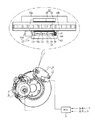
図1は本発明に係る安全制動機能を備えた制動装置の構成図であり、本発明の制動装置は、ブレーキペダルの操作時に制動がなされるように制御するECU1、正常制動時にホイールディスクを押さえて制動するように前記ECU1によって制御されるメイン制動機2、および前記メイン制動機2の故障を検知したECU1を介してホイールディスクを押さえて安全のための非常制動を実現するように、ホイールディスクに取り付けられて補助的な制動機能を実現するサブ制動機10から構成される。 FIG. 1 is a configuration diagram of a braking device having a safety braking function according to the present invention. The braking device according to the present invention controls an ECU 1 that controls braking so as to operate when a brake pedal is operated. The wheel disc so as to realize emergency braking for safety by pressing the wheel disc via the main brake 2 controlled by the ECU 1 so as to brake and the ECU 1 detecting the failure of the main brake 2 It is comprised from the subbrake 10 which is attached to and implement | achieves an auxiliary | assistant braking function.
このために、本実施形態による前記メイン制動機2はEWB(Electro Wedge Brake)であって、これは、通常、アクチュエータを介して作動するウェッジ組立体を利用してブレーキパッドをディスク側に加圧することによって摩擦させることで、入力を倍力するウェッジ作用によって制動を実現する方式である。 For this purpose, the main brake 2 according to the present embodiment is an EWB (Electro Wedge Break), which normally presses the brake pads to the disk side using a wedge assembly that operates via an actuator. In this method, braking is realized by a wedge action that boosts the input by friction.
また、本発明では、メイン制動機として、前記EWBタイプのメイン制動機を用いることなく、電動ブレーキ装置であるEMB(Electro Mechanical Brake)を適用することができ、これは、モータ動力をスクリューを利用して軸方向直線移動力に切り換えてホイールディスクを加圧する方式である。
このような、EWB(Electro Wedge Brake)やEMB(Electro Mechanical Brake)を通常BBW(Brake By Wire)技術と称し、本実施形態では、メイン制動機2はEWB方式を適用して説明する。
Further, in the present invention, an EMB (Electro Mechanical Break) that is an electric brake device can be applied without using the EWB type main brake as the main brake, and this uses a screw for motor power. Then, the wheel disk is pressurized by switching to the axial linear movement force.
Such an EWB (Electro Wake Break) or EMB (Electro Mechanical Break) is referred to as a normal BBW (Brake By Wire) technology, and in the present embodiment, the main brake 2 is described by applying the EWB method.
このような前記メイン制動機2は、一般的に、ECU1によって制御され、回転を直線移動に切り換える切り換え部を備えたモータ3と、前記モータ3の駆動によって提供される直線移動を利用して、ホイールディスクを加圧する入力を倍力するメインウェッジ4、およびホイールディスクを囲み、前記メインウェッジ4の移動時、ホイールディスクを加圧するインナー・アウターパッド(21、22)を備えたキャリパー5から構成される。
The main brake 2 is generally controlled by the ECU 1 and includes a motor 3 having a switching unit that switches rotation to linear movement, and linear movement provided by driving the motor 3. A
これと共に、前記メイン制動機2には、ホイールディスクに対するパッド(22、23)の設定間隔維持のための摩耗補正と、モータ3の故障やメインウェッジ4の作動不良によるF−S(Fail−Safe)の実現、および電子式駐車ブレーキであるEPB(Electric Parking Brake)機能も共に実現できるように、各々に要求される装置であるNSL(Non−Self Locking)タイプのスクリュー構造とソレノイドを備えており、これはEWBタイプの制動装置の一般的な構成である。
At the same time, the main brake 2 includes a wear correction for maintaining a set interval of the pads (22, 23) with respect to the wheel disc, and a FS (Fail-Safe) due to a failure of the motor 3 or a malfunction of the
また、前記メインウェッジ4は、キャリパー5に固定された固定板4bと、前記固定板4bに対しローラ4cを介して対向し、前記モータ3の駆動によって切り換えられた直線移動力を受けて固定板4bに対し直線移動する移動板4aとから構成される。
The
このような構造を有する前記メインウェッジ4から発生するウェッジ(Wedge)現象を利用した自己倍力(Self−Energizing)作用は同分野制動機でよく知られたものであり、これは、固定板4bに対して移動板4aが直線移動すれば、前記固定・移動板(4b、4a)間において溝に位置したローラ4cの位置移動が発生し、これにより、移動板4aが固定板4bから離れてパッドをホイールディスク側に押して追加的な入力(Input Force)を発生する。
The self-energizing action using the wedge phenomenon generated from the
このような前記メイン制動機2の作動は、一例としてECU1がモータ2を回転させれば、図2に示すように、メインウェッジ4が作用してパッドをホイールディスク側に押すようにウェッジ作用を発生する。
すなわち、モータ3の回転がEPB(Electro Parking Brake)のケーブル引張力切り換え部のように軸とナット間のスクリュー結合構造によって直線移動に切り換えられると、メインウェッジ4の移動板4aが移動してローラ4cの位置も移動し、前記移動板4aの継続的な前進移動により、図2(A)から(C)のように運動してウェッジ作用を発生させる。
For example, when the ECU 1 rotates the motor 2 as shown in FIG. 2, the main brake 2 operates as shown in FIG. 2 so that the
That is, when the rotation of the motor 3 is switched to the linear movement by the screw coupling structure between the shaft and the nut as in the cable pulling force switching unit of EPB (Electro Parking Break), the moving
次に、制動解除時、モータ3の逆回転により、図2(D)、(E)のように、移動板4aが初期状態に復帰し、車両後進制動時には、図2(F)、(G)のように、移動板4aが、前進制動時、逆に移動して同一のウェッジ作用を発生させる。
このようなメイン制動機2に対し、ECU1がメイン制動機2のモータ3の故障時、独自に駆動させるサブ制動機10もメイン制動機2と同様にウェッジ作用を実現するサブウェッジ13を備える。
Next, when the brake is released, the moving
In contrast to such a main brake 2, the sub brake 10 that the ECU 1 independently drives when the motor 3 of the main brake 2 fails is also provided with a
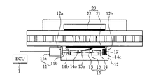
すなわち、前記サブ制動機10は、図1に示すように、ホイールディスクを囲み、インナー・アウターパッド(21、22)を備えたキャリパー12を備え、ECU1の制御によってオン・オフになるソレノイド11aを備えた制動操作部11と共に、前記ソレノイド11aを介して移動し、パッド20をホイールディスク側に押して加圧するウェッジ作用を実現するサブウェッジ13を備えて構成される。
That is, as shown in FIG. 1, the sub brake 10 includes a
このために、前記制動操作部11は、メイン制動機2のモータ3の故障を検知するECU1によってオンになる時、長く引き出されて荷重を加えるロッド11bを備えたソレノイド11aからなる。
ここで、前記ソレノイド11aはロッド11bがサブウェッジ13を側面から押す位置に設けられ、キャリパー12を利用して固定される。
For this purpose, the
Here, the
また、前記キャリパー12には左・右ストッパー(12a、12b)がさらに形成され、前記左・右ストッパー(12a、12b)はサブウェッジ13の両側面に対し所定間隔をおいた位置においてサブウェッジ13の移動距離を拘束する。
すなわち、前記左・右ストッパー(12a、12b)は、前進や後進制動時、前・後に移動するサブウェッジ13の過度な移動を遮断するためのものであり、このような間隔はサブ制動機10に要求される制動力大きさに合わせて算定される。
Further, left and right stoppers (12a, 12b) are further formed on the
That is, the left and right stoppers (12a, 12b) are for blocking excessive movement of the sub-wedge 13 that moves forward / backward during forward or reverse braking. It is calculated according to the magnitude of braking force required.
しかし、前記左・右ストッパー(12a、12b)はソレノイド11aを利用して作らないこともでき、これは、ソレノイド11aから引き出されてサブウェッジ13を押すロッド11bの引き出し長さを一定値、すなわち、サブウェッジ13の安定的な作動のための移動距離に合わせてロッド11bの長さを定めて実現することができる。
However, the left and right stoppers (12a, 12b) may not be made by using the
また、前記サブウェッジ13は、キャリパー5に固定された固定板15と、前記固定板15に対しローラ16を介して対向し、ソレノイド11aが加える直線移動力を受けて固定板15に対し直線移動する移動板14とから構成される。
The sub-wedge 13 is opposed to the fixed
これに加え、前記サブウェッジ13にはキャリパー12を介して弾性的に支持されるリターンスプリング17がさらに備えられ、前記リターンスプリング17はソレノイド11aのオフ切り換え時、移動板14の初期復帰を手伝う。
In addition, the sub-wedge 13 is further provided with a
これと共に、前記移動板14には間隔をおいて固定板15を収容するように両側面に左・右延長端(14b、14c)が突出延長され、このような左側延長端14bはソレノイド11aのロッド11bから加圧力を受ける反面、右側延長端14cはキャリパー12と共にリターンスプリング17を弾性的に支持する作用をする。
At the same time, left and right extension ends (14b, 14c) are projected and extended on both side surfaces so as to accommodate the fixed
また、前記ローラ16が載置されるように移動・固定板(14、15)に窪んだ溝であるウェッジ面(14a、15a)は制動力を安定的に形成するための幾何学的な構造を有し、これは、ローラ16から発生する摩擦力を入力(Input Force)として活用して制動力を付加することにより、ウェッジ面(14a、15a)に対するローラ16の摩擦力制御が不十分である場合にホイールジャミング(Wheel Jamming)が発生し、それによって過度な制動力が発生し得る脆弱性があるため、それを防止するためである。
Further, the wedge surfaces (14a, 15a), which are grooves recessed in the moving / fixing plates (14, 15) so that the
これは、前記サブウェッジ13の作動によるローラ16の摩擦角が、ウェッジ面(14a、15a)が有するウェッジ角より大きく形成されないようにするためであり、このために前記ウェッジ面(14a、15a)が有する角度は摩擦係数>tan(ウェッジ面角度)のような関係を有する範囲内で決定される。
This is to prevent the friction angle of the
これにより、前記サブ制動機10が作動、すなわち、ECU1がメイン制動機2のモータ3の故障状態を検知したり、メイン制動機2側の電源供給異常を検知したりして、メイン制動機2を介した正常な車両制動がなされない時、前記ECU1はサブウェッジ13を介したウェッジ作用によって非常制動力を提供し、これによって車両を安全な場所に移動させることができる。 Thereby, the sub brake 10 operates, that is, the ECU 1 detects a failure state of the motor 3 of the main brake 2 or detects a power supply abnormality on the main brake 2 side. When normal vehicle braking is not performed via the ECU 1, the ECU 1 provides an emergency braking force by the wedge action via the sub-wedge 13, thereby moving the vehicle to a safe place.
このような作動実現は、ECU1がソレノイド11aをオンにすれば、図3に示すように、前記ソレノイド11aのロッド11bが引き出されてサブウェッジ13を押し、前記サブウェッジ13の押されによってローラ16の位置移動が起こり、インナーパッド21をホイールディスクに加圧させるウェッジ作用を発生させる。
すなわち、前記ソレノイド11aから加えられる荷重によって移動板14がリターンスプリング17を圧縮しながら押し出されば、移動板14と固定板15のウェッジ面(14a、15a)間に位置したローラ16が摩擦を起こしながら位置移動する。
Such operation is realized when the ECU 1 turns on the
That is, when the moving
このような前記ローラ16の位置移動は、移動板14が押し出されると同時に固定板15から離れ、これによって移動板14がインナーパッド21をホイールディスク側に押し、ホイールディスクを拘束しながら制動力を発生させる。
Such a movement of the position of the
このような前記サブウェッジ13の自己倍力ウェッジ作用は、メイン制動機2を通じて説明したのと同様に実現され、前記サブウェッジ13の作用により、運転者はメイン制動機2の異常状況においても車両を安全に制御しながら移動させることができる。 Such a self-boosting wedge action of the sub-wedge 13 is realized in the same manner as described through the main brake 2, and the action of the sub-wedge 13 allows the driver to operate the vehicle even in an abnormal situation of the main brake 2. Can be moved while safely controlling.
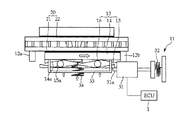
一方、本発明のサブ制動機10はサブウェッジ13の作動実現を様々な方式で達成することができ、一例として、サブウェッジ13の作動のためにスプリング加圧力を利用するように構成することができる。
すなわち、サブウェッジ13が移動板14と固定板15およびウェッジ面(14a、15a)間に位置したローラ16からなる構造において、前記移動板14にはホイールディスク側に移動板14を加圧する圧縮スプリング34の荷重が作用するように付加し、オン・オフになるソレノイド31を利用して、前記圧縮スプリング34の加圧力がメイン制動機2の故障時にだけ伝達されるように構成する。
On the other hand, the sub-brake 10 of the present invention can achieve the operation of the sub-wedge 13 in various ways. For example, the sub-brake 10 can be configured to use a spring pressure for operating the sub-wedge 13. it can.
That is, in the structure in which the sub-wedge 13 is composed of the moving
このような作用のために、前記圧縮スプリング34は、一端は移動板14に固定され、他端は移動板14に固定されて移動板14と共に動くウェッジフレーム33に固定させることにより、前記圧縮スプリング34が加える荷重がウェッジフレーム33を介して移動板14をホイールディスク側に押すことができる。
For this operation, one end of the
これと共に、前記ソレノイド31はソレノイドロッド31aがウェッジフレーム33の内側に挿入されるようにサブウェッジ13の側面部位に設けられ、これは、前記ソレノイド31がオンまたはオフになった状態でソレノイドロッド31aがウェッジフレーム33を遮断することにより、圧縮スプリング34から持続的な荷重を受けるウェッジフレーム33の移動を遮断することができる。
At the same time, the
これに加え、前記ソレノイド31には引張スプリング32がさらに備えられ、前記引張スプリング32は、ソレノイド31が作動してから復帰する時、ソレノイドロッド31aをサブウェッジ13側に押すように作用する。
In addition, the
また、前記キャリパー12には左・右ストッパー(12a、12b)がさらに形成され、前記左・右ストッパー(12a、12b)はサブウェッジ13の両側面に対し所定間隔をおいた位置においてサブウェッジ13の移動距離を拘束する。
Further, left and right stoppers (12a, 12b) are further formed on the
このように、前記圧縮スプリング34を利用した方式もサブウェッジ13のウェッジ作用によって非常制動力を提供し、すなわち、ECU1がメイン制動機2のモータ3の故障状態を検知したり、メイン制動機2側の電源供給異常を検知したりして、ソレノイド31をオンまたはオフに切り換えれば、ソレノイドロッド31aを介した拘束作用が解除されてサブウェッジ13が作動する。
As described above, the system using the
すなわち、図5に示すように、ソレノイドロッド31aを介した拘束作用が解除されたサブウェッジ13は圧縮スプリング34が加える荷重によって押し出され、これは、前記圧縮スプリング34がウェッジフレーム33を押すようになり、ウェッジフレーム33は移動板14を押し、インナーパッド21がホイールディスク側に押し出されるようになる。
That is, as shown in FIG. 5, the
このようなホイールディスクに対する接触は、ホイールディスクを介した反力、すなわち、回転するホイールディスクによってインナーパッド21がホイールディスクの回転方向に押し出され、前記インナーパッド21の押されは移動板14を同一方向に共に移動させる。
Such contact with the wheel disc is caused by reaction force through the wheel disc, that is, the
このような前記移動板14の押されにより、移動板14と固定板15のウェッジ面(14a、15a)間に位置したローラ16が摩擦を起こしながら位置移動し、これによって移動板14が固定板15から離れ、インナーパッド21がホイールディスクをより加圧して車両停止のための制動力を発生させる。
As the moving
このように、前記圧縮スプリング34を介した荷重がウェッジフレーム33に加圧力を加えることにより、サブウェッジ13に加える別途の入力がない状態においてもインナーパッド21をホイールディスク側に押し、ウェッジ作用による制動力を発生させ、運転者がメイン制動機2の異常状況においても車両を安全に制御しながら移動させることができる。
In this way, when the load via the
1:ECU
2:メイン制動機
3:モータ
4:メインウェッジ
4a、14:移動板
4b、15:固定板
4c、16:ローラ
5、12:キャリパー
10:サブ制動機
11:制動操作部
11a、31:ソレノイド
11b、31a:ロッド
12a、12b:左・右ストッパー
13:サブウェッジ
14a、15a:ウェッジ面
14b、14c:左・右延長端
17:リターンスプリング
20:パッド
21、22:インナー・アウターパッド
32:引張スプリング
33:ウェッジフレーム
34:圧縮スプリング
1: ECU
2: Main brake 3: Motor 4:
Claims (10)
ホイールディスクを加圧するパッドを備えたキャリパーを備え、前記ECUの制御により駆動されるモータからホイールディスクを押さえて制動する出力トルクを発生させるメイン制動機;および
前記メイン制動機から離隔した位置においてホイールディスクを加圧するパッドを備えたキャリパーを備え、前記メイン制動機の故障を検知したECUから発生した制御信号によって前記パッドをホイールディスク側に押して車両を制動させるサブ制動機;
から構成されると共に、
前記サブ制動機は、ホイールディスクを囲み、インナー・アウターパッドを備えたキャリパー;
ECUの制御によってオン・オフになり、荷重を加えるように引き出されるロッドを備えたソレノイド;および
前記ソレノイドロッドから加えられる荷重によって押し出され、パッドをホイールディスク側に押すと共にウェッジ作用を実現するように、ソレノイドロッドから荷重を受ける移動板と、キャリパーに固定された固定板、および前記移動・固定板に窪んだウェッジ面に位置したローラからなるサブウェッジ;
から構成されることを特徴とする安全制動機能を備えた制動装置。 ECU which detects operation of a brake pedal via a sensor and performs control so that braking is performed;
A main brake having a caliper having a pad for pressurizing the wheel disc, and generating an output torque for pressing and braking the wheel disc from a motor driven by the control of the ECU; and a wheel at a position separated from the main brake A sub brake that includes a caliper including a pad for pressurizing the disk and brakes the vehicle by pushing the pad toward the wheel disk by a control signal generated from an ECU that detects a failure of the main brake;
And consisting of
The sub brake includes a caliper that surrounds the wheel disc and includes inner and outer pads;
A solenoid having a rod that is turned on and off under the control of the ECU and pulled out to apply a load; and pushed by a load applied from the solenoid rod to push the pad toward the wheel disc and realize a wedge action A sub-wedge comprising a moving plate that receives a load from the solenoid rod, a fixed plate fixed to the caliper, and a roller positioned on a wedge surface recessed in the moving / fixing plate;
A braking device having a safety braking function characterized by comprising:
前記モータの駆動によって提供される直線移動を利用して、ホイールディスクを加圧する入力を倍力するローラと移動・固定板とからなるメインウェッジ;および
ホイールディスクを囲み、前記メインウェッジの移動時、ホイールディスクを加圧するインナー・アウターパッドを備えたキャリパー;
から構成されることを特徴とする、請求項1に記載の安全制動機能を備えた制動装置。 The main brake is an EWB (Electro Wedge Break) type motor, which is controlled by an ECU and includes a switching unit that switches rotation to linear movement;
A main wedge composed of a roller and a moving / fixing plate for boosting an input for pressurizing the wheel disc using a linear movement provided by driving of the motor; and surrounding the wheel disc, when the main wedge moves, Calipers with inner and outer pads to pressurize the wheel discs;
The braking device having a safety braking function according to claim 1, wherein
ホイールディスクを加圧するパッドを備えたキャリパーを備え、前記ECUの制御により駆動されるモータからホイールディスクを押さえて制動する出力トルクを発生させるメイン制動機;および
前記メイン制動機から離隔した位置においてホイールディスクを加圧するパッドを備えたキャリパーを備え、前記メイン制動機の故障を検知したECUから発生した制御信号によって前記パッドをホイールディスク側に押して車両を制動させるサブ制動機;
から構成されると共に、
前記サブ制動機は、ホイールディスクを囲み、インナー・アウターパッドを備え、サブウェッジに間隔をおいて左・右ストッパーを形成したキャリパー;
ホイールディスクを拘束しながら、ホイールディスクの回転方向に押し出されるパッドと共に押し出される移動板と、キャリパーに固定された固定板、および前記移動・固定板に窪んだウェッジ面に位置したローラからなるサブウェッジ;
一端は前記移動板に固定され、他端は移動板と共に動くように移動板に固定されたウェッジフレームに持続的な荷重を加える圧縮スプリング;および
前記ウェッジフレームを拘束するソレノイドロッドを備え、ECUの制御によってオン・オフになり、ウェッジフレームの拘束状態を切り換えるソレノイド;
から構成されることを特徴とする安全制動機能を備えた制動装置。 ECU which detects operation of a brake pedal via a sensor and performs control so that braking is performed;
A main brake having a caliper with a pad for pressing the wheel disc, and generating an output torque for pressing and braking the wheel disc from a motor driven by the control of the ECU; and
A caliper having a pad for pressurizing the wheel disc at a position separated from the main brake is provided, and the vehicle is braked by pushing the pad toward the wheel disc by a control signal generated from an ECU that detects a failure of the main brake. Sub brake;
And consisting of
The sub brake includes a caliper that surrounds a wheel disc, includes inner and outer pads, and has left and right stoppers spaced from the sub wedge;
A sub-wedge comprising a moving plate pushed together with a pad pushed in the rotating direction of the wheel disc while restraining the wheel disc, a fixed plate fixed to the caliper, and a roller positioned on the wedge surface recessed in the moving / fixing plate ;
One end is fixed to the moving plate, and the other end includes a compression spring that applies a continuous load to a wedge frame fixed to the moving plate so as to move together with the moving plate; and a solenoid rod that restrains the wedge frame, A solenoid that is turned on and off by control and switches the restraint state of the wedge frame;
A braking device having a safety braking function characterized by comprising:
Applications Claiming Priority (2)
| Application Number | Priority Date | Filing Date | Title |
|---|---|---|---|
| KR1020080125713A KR101098144B1 (en) | 2008-12-11 | 2008-12-11 | Brake System having safe braking function |
| KR10-2008-0125713 | 2008-12-11 |
Publications (2)
| Publication Number | Publication Date |
|---|---|
| JP2010137848A JP2010137848A (en) | 2010-06-24 |
| JP5282012B2 true JP5282012B2 (en) | 2013-09-04 |
Family
ID=42221088
Family Applications (1)
| Application Number | Title | Priority Date | Filing Date |
|---|---|---|---|
| JP2009261033A Expired - Fee Related JP5282012B2 (en) | 2008-12-11 | 2009-11-16 | Braking device with safety braking function |
Country Status (5)
| Country | Link |
|---|---|
| US (1) | US8177037B2 (en) |
| JP (1) | JP5282012B2 (en) |
| KR (1) | KR101098144B1 (en) |
| CN (1) | CN101780795B (en) |
| DE (1) | DE102009055639B4 (en) |
Families Citing this family (27)
| Publication number | Priority date | Publication date | Assignee | Title |
|---|---|---|---|---|
| KR101574349B1 (en) * | 2009-09-08 | 2015-12-11 | 현대모비스 주식회사 | Electronic wedge brake device |
| KR101228492B1 (en) * | 2010-06-28 | 2013-01-31 | 현대모비스 주식회사 | Braking Control System for The Vehicle and Method of The same |
| KR101894382B1 (en) * | 2011-04-15 | 2018-09-04 | 현대모비스 주식회사 | Apparatus And Method Controlling Brake Power Using Car |
| JP2012237408A (en) * | 2011-05-12 | 2012-12-06 | Tbk:Kk | Disk brake device |
| JP5754547B2 (en) | 2012-04-07 | 2015-07-29 | トヨタ自動車株式会社 | Friction brake device |
| WO2013157646A1 (en) * | 2012-04-20 | 2013-10-24 | トヨタ自動車株式会社 | Friction brake device |
| CN102729962A (en) * | 2012-06-21 | 2012-10-17 | 青岛智远汽车部件有限公司 | Electronic wedge brake system |
| US9777782B2 (en) * | 2013-06-19 | 2017-10-03 | Kelsey-Hayes Company | Shared anchor bracket for a disc brake assembly having separate service and parking brake assemblies |
| JP5991694B2 (en) * | 2013-07-17 | 2016-09-14 | 株式会社ソニー・インタラクティブエンタテインメント | Optical disk drive |
| JP6575175B2 (en) * | 2015-07-02 | 2019-09-18 | 三菱自動車工業株式会社 | Electric brake device |
| JP6325586B2 (en) * | 2016-02-18 | 2018-05-16 | トヨタ自動車株式会社 | Motor drive unit |
| FR3056271B1 (en) * | 2016-09-21 | 2022-03-11 | Jean Marc Loriot | FAILURE OF CURRENT BRAKING SYSTEM |
| US9783288B1 (en) * | 2016-12-07 | 2017-10-10 | Kitty Hawk Corporation | Lift fan position lock mechanism |
| JP6624094B2 (en) * | 2017-01-27 | 2019-12-25 | トヨタ自動車株式会社 | Braking device |
| DE102018100072B4 (en) | 2017-01-27 | 2020-06-18 | Toyota Jidosha Kabushiki Kaisha | Brake unit |
| JP6855832B2 (en) | 2017-02-21 | 2021-04-07 | トヨタ自動車株式会社 | Vehicle drive system |
| JP2019043228A (en) * | 2017-08-30 | 2019-03-22 | 株式会社シマノ | Electric brake system |
| CN107816498A (en) * | 2017-11-17 | 2018-03-20 | 金华职业技术学院 | A kind of new automobile brake-by-wire device |
| CN107795609A (en) * | 2017-11-17 | 2018-03-13 | 金华职业技术学院 | A kind of automobile electromechanical brake |
| KR102539406B1 (en) * | 2019-04-22 | 2023-06-01 | 히다치 아스테모 가부시키가이샤 | controller |
| KR102082378B1 (en) | 2019-11-14 | 2020-02-27 | 주식회사 인터라온 | Electromechanical brake realizing emergency braking function using pneumatic pressure |
| KR102730231B1 (en) * | 2020-08-24 | 2024-11-13 | 현대모비스 주식회사 | Method And Apparatus for Controlling Electrohydraulic Brake |
| KR102593295B1 (en) * | 2020-12-23 | 2023-10-24 | 스톨츠 주식회사 | Disk coupling unit |
| CN114312710B (en) * | 2021-07-20 | 2023-02-10 | 华为数字能源技术有限公司 | Parking mechanism, EMB system and vehicle |
| WO2023097373A1 (en) * | 2021-12-02 | 2023-06-08 | Eurospares Depot Holdings Pty Ltd | Emergency disc brake assembly |
| IT202100030635A1 (en) | 2021-12-03 | 2023-06-03 | Brembo Spa | METHOD OF CONTROL OF A BRAKING SYSTEM IN BBW TECHNOLOGY FOR THE DISTRIBUTION OF BRAKING FORCES FOR SERVICE BRAKING OF A VEHICLE |
| DE102024207820A1 (en) | 2024-08-16 | 2026-03-05 | Robert Bosch Gesellschaft mit beschränkter Haftung | Method for operating a braking system |
Family Cites Families (18)
| Publication number | Priority date | Publication date | Assignee | Title |
|---|---|---|---|---|
| JPH0662079B2 (en) * | 1985-11-14 | 1994-08-17 | トヨタ自動車株式会社 | Brake system for automobile |
| JPS6345430U (en) * | 1986-09-10 | 1988-03-26 | ||
| DE19626901C2 (en) * | 1996-07-04 | 2000-04-20 | Daimler Chrysler Ag | Disc brake with at least two brake pad sets |
| DE19831541A1 (en) * | 1998-07-14 | 2000-03-02 | Continental Teves Ag & Co Ohg | Brake actuation method, brake control, brake system and motor vehicles with such a brake system |
| JP4025342B2 (en) * | 1999-09-21 | 2007-12-19 | トヨタ自動車株式会社 | Brake control device |
| DE10154178B4 (en) * | 2001-05-21 | 2004-05-13 | Estop Gmbh | Self-energizing electromechanical brake with variable wedge angle |
| US6752247B2 (en) * | 2002-05-06 | 2004-06-22 | Ford Global Technologies, Llc | Method and an assembly for braking a selectively moveable assembly having a controllably varying amount of self energization |
| KR100498690B1 (en) | 2002-06-05 | 2005-07-01 | 현대모비스 주식회사 | Electric disk break system using electromagnetic force |
| DE10255192B4 (en) * | 2002-11-27 | 2015-03-19 | Robert Bosch Gmbh | Electromechanical brake |
| DE10302516A1 (en) * | 2003-01-23 | 2004-08-05 | Robert Bosch Gmbh | Disc brake with mechanical self-reinforcement |
| DE10336284A1 (en) * | 2003-08-07 | 2005-03-10 | Bosch Gmbh Robert | Electromechanical disc brake with self-amplification |
| DE10347792A1 (en) * | 2003-10-14 | 2005-05-12 | Bosch Gmbh Robert | wheel brake |
| DE102004029841A1 (en) | 2004-06-19 | 2006-01-05 | Robert Bosch Gmbh | Self-energizing electromechanical friction brake |
| KR100610120B1 (en) | 2004-12-16 | 2006-08-09 | 현대자동차주식회사 | Car disc brake device |
| JP2007064433A (en) * | 2005-09-01 | 2007-03-15 | Advics:Kk | Disc brake device |
| DE102005055085B4 (en) * | 2005-09-29 | 2020-09-24 | Robert Bosch Gmbh | Combined service and parking brake device as well as a method for performing emergency braking |
| US20070199781A1 (en) * | 2006-02-27 | 2007-08-30 | Robert Bosch Corporation | Disc Brake |
| US7837014B2 (en) * | 2006-04-24 | 2010-11-23 | Martin Schneider | High performance retrofit disk brake kit and method of use |
-
2008
- 2008-12-11 KR KR1020080125713A patent/KR101098144B1/en not_active Expired - Fee Related
-
2009
- 2009-11-05 US US12/613,451 patent/US8177037B2/en not_active Expired - Fee Related
- 2009-11-16 JP JP2009261033A patent/JP5282012B2/en not_active Expired - Fee Related
- 2009-11-25 CN CN2009102241302A patent/CN101780795B/en not_active Expired - Fee Related
- 2009-11-25 DE DE102009055639A patent/DE102009055639B4/en not_active Expired - Fee Related
Also Published As
| Publication number | Publication date |
|---|---|
| JP2010137848A (en) | 2010-06-24 |
| US8177037B2 (en) | 2012-05-15 |
| US20100147633A1 (en) | 2010-06-17 |
| KR20100067240A (en) | 2010-06-21 |
| CN101780795A (en) | 2010-07-21 |
| DE102009055639A1 (en) | 2010-07-01 |
| KR101098144B1 (en) | 2011-12-26 |
| DE102009055639B4 (en) | 2011-06-09 |
| CN101780795B (en) | 2013-11-27 |
Similar Documents
| Publication | Publication Date | Title |
|---|---|---|
| JP5282012B2 (en) | Braking device with safety braking function | |
| KR100879890B1 (en) | Single-function electronic wedge brake system with solenoid | |
| CN101391604B (en) | Single motor electronic wedge brake system locking parking force | |
| JP5126990B2 (en) | Safety braking device for stopping vehicle in emergency and vehicle braking device using the same | |
| KR101786337B1 (en) | Electro-Mechanical Brake | |
| KR101511437B1 (en) | Electro mechanical brake Apparatus | |
| US7588128B2 (en) | Self-boosting electromechanical vehicle brake | |
| CN108884889B (en) | Shaft nut assembly with multiple stop cams | |
| KR101816396B1 (en) | Electro-Mechanical Brake | |
| CN113494548A (en) | Friction braking system for vehicle | |
| JP2546348Y2 (en) | Brake actuator | |
| KR20100030285A (en) | Electro mechanical brake system having ratchet typed electro parking brake device | |
| KR20100030010A (en) | Electro mechanical brake system having electric parking brake function | |
| KR101350571B1 (en) | Wheel jamming protected typed wedge assembly for Vehicle Brake Sysrem | |
| KR101318003B1 (en) | Additional functions embodiment using solenoid mechanism typed Single Motor Electric Wedge Brake Sysrem | |
| KR101329387B1 (en) | Additional functions embodiment using solenoid mechanism typed Single Motor Electric Wedge Brake Sysrem | |
| JP7760978B2 (en) | Vehicle braking system | |
| KR101317099B1 (en) | Electric Parking Brake gearing typed Single Motor Electric Wedge Brake System | |
| KR20090006969A (en) | Single-Motor Electronic Wedge Brake System with Solenoid Mechanism | |
| KR20090006968A (en) | Single motor electric wedge brake system with additional functions through solenoid and motor linkage | |
| KR20080113532A (en) | Single motor electronic wedge brake system with pad wear adjustment using double latch | |
| KR101655479B1 (en) | Remain Drag Torque Preventing type Electro Mechanical Brake | |
| KR20100008413A (en) | Low voltage motor typed electric mechanical brake system | |
| KR20100030011A (en) | Electric mechanical brake system having electric parking brake function | |
| KR20090064148A (en) | Single Motor Type Electronic Wedge Brake System |
Legal Events
| Date | Code | Title | Description |
|---|---|---|---|
| A977 | Report on retrieval |
Free format text: JAPANESE INTERMEDIATE CODE: A971007 Effective date: 20120214 |
|
| A131 | Notification of reasons for refusal |
Free format text: JAPANESE INTERMEDIATE CODE: A131 Effective date: 20120221 |
|
| A521 | Written amendment |
Free format text: JAPANESE INTERMEDIATE CODE: A523 Effective date: 20120521 |
|
| A131 | Notification of reasons for refusal |
Free format text: JAPANESE INTERMEDIATE CODE: A131 Effective date: 20121002 |
|
| A521 | Written amendment |
Free format text: JAPANESE INTERMEDIATE CODE: A523 Effective date: 20121225 |
|
| TRDD | Decision of grant or rejection written | ||
| A01 | Written decision to grant a patent or to grant a registration (utility model) |
Free format text: JAPANESE INTERMEDIATE CODE: A01 Effective date: 20130430 |
|
| A61 | First payment of annual fees (during grant procedure) |
Free format text: JAPANESE INTERMEDIATE CODE: A61 Effective date: 20130527 |
|
| R150 | Certificate of patent or registration of utility model |
Free format text: JAPANESE INTERMEDIATE CODE: R150 Ref document number: 5282012 Country of ref document: JP Free format text: JAPANESE INTERMEDIATE CODE: R150 |
|
| R250 | Receipt of annual fees |
Free format text: JAPANESE INTERMEDIATE CODE: R250 |
|
| R250 | Receipt of annual fees |
Free format text: JAPANESE INTERMEDIATE CODE: R250 |
|
| R250 | Receipt of annual fees |
Free format text: JAPANESE INTERMEDIATE CODE: R250 |
|
| R250 | Receipt of annual fees |
Free format text: JAPANESE INTERMEDIATE CODE: R250 |
|
| LAPS | Cancellation because of no payment of annual fees |