JP5281823B2 - Method and apparatus for controlling combustion in a gas turbine - Google Patents
Method and apparatus for controlling combustion in a gas turbine Download PDFInfo
- Publication number
- JP5281823B2 JP5281823B2 JP2008133899A JP2008133899A JP5281823B2 JP 5281823 B2 JP5281823 B2 JP 5281823B2 JP 2008133899 A JP2008133899 A JP 2008133899A JP 2008133899 A JP2008133899 A JP 2008133899A JP 5281823 B2 JP5281823 B2 JP 5281823B2
- Authority
- JP
- Japan
- Prior art keywords
- gaseous fuel
- wobbe index
- fuel
- value
- mixture
- Prior art date
- Legal status (The legal status is an assumption and is not a legal conclusion. Google has not performed a legal analysis and makes no representation as to the accuracy of the status listed.)
- Expired - Fee Related
Links
Images


Classifications
-
- F—MECHANICAL ENGINEERING; LIGHTING; HEATING; WEAPONS; BLASTING
- F23—COMBUSTION APPARATUS; COMBUSTION PROCESSES
- F23N—REGULATING OR CONTROLLING COMBUSTION
- F23N1/00—Regulating fuel supply
- F23N1/002—Regulating fuel supply using electronic means
-
- F—MECHANICAL ENGINEERING; LIGHTING; HEATING; WEAPONS; BLASTING
- F02—COMBUSTION ENGINES; HOT-GAS OR COMBUSTION-PRODUCT ENGINE PLANTS
- F02C—GAS-TURBINE PLANTS; AIR INTAKES FOR JET-PROPULSION PLANTS; CONTROLLING FUEL SUPPLY IN AIR-BREATHING JET-PROPULSION PLANTS
- F02C7/00—Features, components parts, details or accessories, not provided for in, or of interest apart form groups F02C1/00 - F02C6/00; Air intakes for jet-propulsion plants
- F02C7/22—Fuel supply systems
- F02C7/224—Heating fuel before feeding to the burner
-
- F—MECHANICAL ENGINEERING; LIGHTING; HEATING; WEAPONS; BLASTING
- F02—COMBUSTION ENGINES; HOT-GAS OR COMBUSTION-PRODUCT ENGINE PLANTS
- F02C—GAS-TURBINE PLANTS; AIR INTAKES FOR JET-PROPULSION PLANTS; CONTROLLING FUEL SUPPLY IN AIR-BREATHING JET-PROPULSION PLANTS
- F02C9/00—Controlling gas-turbine plants; Controlling fuel supply in air- breathing jet-propulsion plants
- F02C9/26—Control of fuel supply
- F02C9/28—Regulating systems responsive to plant or ambient parameters, e.g. temperature, pressure, rotor speed
-
- F—MECHANICAL ENGINEERING; LIGHTING; HEATING; WEAPONS; BLASTING
- F05—INDEXING SCHEMES RELATING TO ENGINES OR PUMPS IN VARIOUS SUBCLASSES OF CLASSES F01-F04
- F05D—INDEXING SCHEME FOR ASPECTS RELATING TO NON-POSITIVE-DISPLACEMENT MACHINES OR ENGINES, GAS-TURBINES OR JET-PROPULSION PLANTS
- F05D2270/00—Control
- F05D2270/30—Control parameters, e.g. input parameters
- F05D2270/303—Temperature
-
- F—MECHANICAL ENGINEERING; LIGHTING; HEATING; WEAPONS; BLASTING
- F23—COMBUSTION APPARATUS; COMBUSTION PROCESSES
- F23K—FEEDING FUEL TO COMBUSTION APPARATUS
- F23K2400/00—Pretreatment and supply of gaseous fuel
- F23K2400/10—Pretreatment
-
- F—MECHANICAL ENGINEERING; LIGHTING; HEATING; WEAPONS; BLASTING
- F23—COMBUSTION APPARATUS; COMBUSTION PROCESSES
- F23K—FEEDING FUEL TO COMBUSTION APPARATUS
- F23K2400/00—Pretreatment and supply of gaseous fuel
- F23K2400/20—Supply line arrangements
- F23K2400/201—Control devices
-
- F—MECHANICAL ENGINEERING; LIGHTING; HEATING; WEAPONS; BLASTING
- F23—COMBUSTION APPARATUS; COMBUSTION PROCESSES
- F23K—FEEDING FUEL TO COMBUSTION APPARATUS
- F23K2900/00—Special features of, or arrangements for fuel supplies
- F23K2900/01041—Heating by using exhaust gas heat
-
- F—MECHANICAL ENGINEERING; LIGHTING; HEATING; WEAPONS; BLASTING
- F23—COMBUSTION APPARATUS; COMBUSTION PROCESSES
- F23K—FEEDING FUEL TO COMBUSTION APPARATUS
- F23K2900/00—Special features of, or arrangements for fuel supplies
- F23K2900/05004—Mixing two or more fluid fuels
-
- F—MECHANICAL ENGINEERING; LIGHTING; HEATING; WEAPONS; BLASTING
- F23—COMBUSTION APPARATUS; COMBUSTION PROCESSES
- F23N—REGULATING OR CONTROLLING COMBUSTION
- F23N2221/00—Pretreatment or prehandling
- F23N2221/06—Preheating gaseous fuel
-
- F—MECHANICAL ENGINEERING; LIGHTING; HEATING; WEAPONS; BLASTING
- F23—COMBUSTION APPARATUS; COMBUSTION PROCESSES
- F23N—REGULATING OR CONTROLLING COMBUSTION
- F23N2221/00—Pretreatment or prehandling
- F23N2221/10—Analysing fuel properties, e.g. density, calorific
-
- F—MECHANICAL ENGINEERING; LIGHTING; HEATING; WEAPONS; BLASTING
- F23—COMBUSTION APPARATUS; COMBUSTION PROCESSES
- F23N—REGULATING OR CONTROLLING COMBUSTION
- F23N2241/00—Applications
- F23N2241/20—Gas turbines
Landscapes
- Engineering & Computer Science (AREA)
- Chemical & Material Sciences (AREA)
- Combustion & Propulsion (AREA)
- Mechanical Engineering (AREA)
- General Engineering & Computer Science (AREA)
- Engine Equipment That Uses Special Cycles (AREA)
- Control Of Eletrric Generators (AREA)
- Control Of Turbines (AREA)
Description
本発明は、ガスタービンにおける燃焼を制御するための方法及び装置に関し、より具体的には、大幅に異なりかつ経時的に変化するウォッベ指数を有する気体燃料の存在下での燃焼を制御するための方法及び装置に関する。 The present invention relates to a method and apparatus for controlling combustion in a gas turbine, and more particularly to controlling combustion in the presence of a gaseous fuel having a significantly different and time-varying Wobbe index. The present invention relates to a method and an apparatus.
外部から吸込んだ空気を加圧する多段圧縮機と、加圧空気に付加した気体燃料の燃焼を行う燃焼室と、燃焼室から流入した気体を膨張させるタービン又はエキスパンダとで通常構成されたガスタービンを使用して電気エネルギーを生成することは、公知である。この時、タービンは、作業機械を作動させるために又は発電機に動力を供給するために利用可能な機械的エネルギーを発生することができる。 A gas turbine generally composed of a multistage compressor that pressurizes air sucked from the outside, a combustion chamber that burns gaseous fuel added to the pressurized air, and a turbine or an expander that expands the gas flowing in from the combustion chamber It is known to generate electrical energy using At this time, the turbine can generate mechanical energy that can be used to operate the work machine or to power the generator.
ガスタービン内で燃料として使用することができる様々なタイプの気体又は気体混合気が存在する。それ故、同じ燃焼室内で各気体又は気体混合気が発生することができる発熱量、従ってエネルギーは、大幅に変化する可能性がある。燃料として使用する気体又は気体混合気の温度もまた、ガスタービンの性能に大きく影響することができる。 There are various types of gases or gas mixtures that can be used as fuel in a gas turbine. Therefore, the amount of heat generated and thus the energy that each gas or gas mixture can generate in the same combustion chamber can vary significantly. The temperature of the gas or gas mixture used as fuel can also greatly affect the performance of the gas turbine.
気体又は気体混合気が一定の供給圧力で燃焼した時に該気体又は気体混合気が発生する熱を測定するために、「ウォッベ指数(Wobbe指数)」と呼ばれるパラメータの使用が知られている。このウォッベ指数は、次式、 In order to measure the heat generated by a gas or gas mixture when it is burned at a constant supply pressure, it is known to use a parameter called the “Wobbe index”. This Wobbe index is given by

IW=ウォッベ指数、
PC=気体の発熱量(最高又は最低)、
TG=気体の温度、
GS=気体の相対密度(又は比重)、
に基づいたものであり、気体の最高(又は最低)発熱量と空気に対して測定した気体の相対密度の平方根との比に等しい。
I W = Wobbe index,
PC = gas calorific value (maximum or minimum),
T G = gas temperature,
G S = relative density (or specific gravity) of gas,
And is equal to the ratio of the highest (or lowest) calorific value of the gas to the square root of the relative density of the gas measured against the air.
従って、気体によって発生される熱は、ウォッベ指数に正比例すると共に、燃料として使用する気体がそこから流出するタービンノズルの面積に正比例する。従って、ウォッベ指数は、特定のガスタービン内で燃料として使用することができる異なる気体の互換性を判定するための重要なパラメータである。 Therefore, the heat generated by the gas is directly proportional to the Wobbe index and directly proportional to the area of the turbine nozzle from which the gas used as fuel flows out. Thus, the Wobbe index is an important parameter for determining the compatibility of different gases that can be used as fuel in a particular gas turbine.
現在、大多数の低エミッションガスタービンは、ウォッベ指数に関して僅かな差異を有する気体燃料で作動するように構成されている。同一のタービンにおける異なる燃料つまりウォッベ指数が大きく異なる燃料の使用は、実際には不規則な燃焼プロセスを招く可能性があり、これが、タービン自体の機能不良、燃焼システム構成要素の有効サイクルの低下、及びエネルギー発生中断の可能性を引き起こすおそれがある。 Currently, the majority of low emission gas turbines are configured to operate with gaseous fuels that have a slight difference with respect to the Wobbe index. The use of different fuels in the same turbine, i.e. fuels with significantly different Wobbe indices, can actually lead to an irregular combustion process, which is a malfunction of the turbine itself, a reduction in the effective cycle of the combustion system components, And the possibility of interruption of energy generation.
従って、開示した主題の有利な特徴の1つは、ガスタービンの燃焼を制御するための方法及び装置を提供することであり、本方法及び装置は、上記の欠点を効果的に解決することができる。 Accordingly, one advantageous feature of the disclosed subject matter is to provide a method and apparatus for controlling the combustion of a gas turbine, which method and apparatus can effectively solve the above disadvantages. it can.
具体的には、開示した主題の有利な特徴のもう1つは、ガスタービンの燃焼を制御するための方法及び装置を提供することであり、本方法及び装置は、タービン自体の性能を損なわずにかつ燃焼室の同一のジオメトリを維持しながら、大幅に異なりかつ経時的に変化するウォッベ指数、従って発熱量を有する気体燃料の使用を可能にする。 In particular, another advantageous feature of the disclosed subject matter is to provide a method and apparatus for controlling the combustion of a gas turbine that does not compromise the performance of the turbine itself. In addition, while maintaining the same geometry of the combustion chamber, it enables the use of gaseous fuels having a Wobbe index that varies greatly and changes over time, and thus a calorific value.
本発明のさらに別の有利な特徴は、ガスタービンの燃焼を制御するための方法及び装置を提供することであり、本方法及び装置は、タービン自体に供給する気体燃料のタイプを急速に変更することを可能にする。 Yet another advantageous feature of the present invention is to provide a method and apparatus for controlling the combustion of a gas turbine, which rapidly changes the type of gaseous fuel supplied to the turbine itself. Make it possible.
本発明のさらに別の有利な特徴は、ガスタービンの燃焼を制御するための方法及び装置を提供することであり、本方法及び装置は、異なるウォッベ指数を有する2つの異なる気体燃料を任意のかつ経時的に変化する割合で混合した状態でもタービン自体が正しく機能することを可能にする。 Yet another advantageous feature of the present invention is to provide a method and apparatus for controlling the combustion of a gas turbine, wherein the method and apparatus are capable of arbitrarily and two different gaseous fuels having different Wobbe indices. It allows the turbine itself to function correctly even when mixed at a rate that changes over time.
本発明のさらに別の有利な特徴は、ガスタービンの燃焼を制御するための方法及び装置を提供することであり、本方法及び装置は、タービンに連結された全てのものによって要求される出力における突然の変動にタービン自体が対処すること(負荷制限)を可能にする。 Yet another advantageous feature of the present invention is to provide a method and apparatus for controlling the combustion of a gas turbine, which method and apparatus are at the power required by everything connected to the turbine. Allows the turbine itself to cope with sudden fluctuations (load limiting).
本発明の第1の態様に基づいて、ガスタービンにおける燃焼を制御する方法は、例えば熱量計又はガスクロマトグラフのような1つ又はそれ以上の適切な計器によって気体燃料の温度、発熱量及び相対密度を測定して、ウォッベ指数を求める段階と、測定したウォッベ指数値を気体燃料について予め定義されたウォッベ指数値と比較する段階と、少なくとも1つの熱交換器によって予め定義されたウォッベ指数値に到達するように気体燃料の温度を調整する段階とを含む。 In accordance with the first aspect of the present invention, a method for controlling combustion in a gas turbine includes the temperature, heating value and relative density of gaseous fuel by one or more suitable instruments such as calorimeters or gas chromatographs, for example. Measuring wobbe index, comparing the measured wobbe index value with a predefined wobbe index value for gaseous fuel, and reaching a wobbe index value predefined by at least one heat exchanger Adjusting the temperature of the gaseous fuel.
本発明のもう1つの態様は、入口ダクトを通してその中に導入された空気を加圧することができる少なくとも1つの圧縮機と、その中で加圧空気を供給ダクトから流入した気体燃料と混合する少なくとも1つの燃焼室と、燃焼室から流入したガスのエネルギーを1つ又はそれ以上の作業機械を作動させるために利用可能な仕事エネルギーに変換することができる少なくとも1つのタービンとを含む形式のガスタービンにおける燃焼を制御するための装置に関する。本装置は、気体燃料の供給ダクトに沿って配置されかつ該気体燃料を加熱することができる少なくとも1つの熱交換器と、気体燃料のウォッベ指数を測定するための、例えば熱量計又はガスクロマトグラフのような1つ又はそれ以上の計器とを含む。 Another aspect of the invention provides at least one compressor capable of pressurizing air introduced therein through an inlet duct, and at least mixing the pressurized air with gaseous fuel flowing from a supply duct therein. A gas turbine of the type comprising a combustion chamber and at least one turbine capable of converting the energy of the gas flowing from the combustion chamber into work energy available for operating one or more work machines The invention relates to an apparatus for controlling combustion in The apparatus comprises at least one heat exchanger arranged along a gaseous fuel supply duct and capable of heating the gaseous fuel and, for example, a calorimeter or gas chromatograph for measuring the Wobbe index of the gaseous fuel. One or more such instruments.
本発明によるガスタービンにおける燃焼を制御するための方法及び装置の特徴及び利点は、添付の概略図を参照して以下の例示的かつ非限定的実施例から一層明確になるであろう。 The features and advantages of the method and apparatus for controlling combustion in a gas turbine according to the present invention will become more apparent from the following illustrative and non-limiting examples with reference to the accompanying schematic drawings.
特に図1を参照すると、この図は、一般的なガスタービンを概略的に示しており、このガスタービンは、入口ダクト12を通してその中に導入された空気を加圧することができる圧縮機10を含む。加圧空気は次に、燃焼室14に送られて、供給ダクト16から流入した気体燃料と混合される。燃焼は、ガス流の温度、流量及びボリュームを増大させ、従ってその中に含まれるエネルギーを増大させる。このガス流は、ダクト18を通してタービン20に向かって導かれ、タービン20は、ガスのエネルギーを、例えばシャフト24によってタービン20に連結された発電機22のような作業機械を作動させるために利用可能な仕事エネルギーに変換する。タービン20はまた、関連するシャフト26を通して圧縮機10を作動させるのに必要なエネルギーを供給し、一方、放出ガスは、出口ダクト28を通してタービン20から排出される。
Referring specifically to FIG. 1, this diagram schematically shows a typical gas turbine, which includes a
本発明によると、一層詳しく後述するように、気体燃料の供給ダクト16上には気体燃料を加熱することができる少なくとも1つの熱交換器30が設けられ、同時にこの熱交換器30の上流及び下流には、例えば熱量計又はガスクロマトグラフのようなウォッベ指数を測定するための1つ又はそれ以上の計器32が配置される。これらの装置のおかげで、燃料自体に関連する最も適正なウォッベ指数値を保証するために気体燃料の加熱を連続的に調整することが可能になる。燃料供給を異なるウォッベ指数を有する燃料に急速に変更した場合には、このシステムはまた、この供給変更による影響を最少にするようにガスタービン構成要素を能動的に制御するのを可能にする。
According to the present invention, at least one
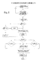
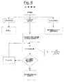
図3〜図6のブロック図及び図2の表に示した気体燃料混合気の2つの例示的類型を参照しながら、本発明による燃焼を制御する方法について以下に説明する。 A method for controlling combustion according to the present invention will now be described with reference to two exemplary types of gaseous fuel mixtures shown in the block diagrams of FIGS. 3-6 and the table of FIG.
図2は、ガスタービンにおいて一般に使用される2つの気体燃料を比較している。「H」で表した燃料は、53.673MJ/Nm3に等しい最大ウォッベ指数値及び低い不活性生成物含有量を特徴としている。他方、燃料Hの代替物としてより低い頻度であるが使用される「G」で表した燃料は、44.3MJ/Nm3に等しい最大ウォッベ指数値及び燃料Hと比べて僅かに高い不活性生成物含有量(約15%)を特徴としている。 FIG. 2 compares two gaseous fuels commonly used in gas turbines. The fuel designated “H” is characterized by a maximum Wobbe index value equal to 53.673 MJ / Nm 3 and a low inert product content. On the other hand, the less frequent but used “G” fuel used as an alternative to fuel H has a maximum Wobbe index value equal to 44.3 MJ / Nm 3 and slightly higher inert production than fuel H It is characterized by its content (about 15%).
図3のブロック図には、技術的な特殊用語で「自力起動」と呼ばれる状態の下での、つまりプラント全体が電源から遮断された後にガスタービンが再始動される場合での本発明によるガスタービンにおける燃焼を制御する方法を示している。これらの状態の下では、気体燃料を加熱するために必要な蒸気が使用不能であり、タービンは、低温の燃料で始動することができなくてはならない。 The block diagram of FIG. 3 shows the gas according to the invention under a condition called “self-starting” in technical terms, ie when the gas turbine is restarted after the entire plant has been disconnected from the power supply. 2 illustrates a method for controlling combustion in a turbine. Under these conditions, the steam necessary to heat the gaseous fuel is not available and the turbine must be able to start with cold fuel.
本方法は、特に高いウォッベ指数を有する使用気体燃料、例えば燃料「H」の温度、発熱量(最低)及び相対密度を熱量計32によって測定する初期フェーズを想定している。燃焼室14に送られる最適燃料流量がひとたび設定されると、前述したように低温燃料(約−5℃〜約25℃)で実行されるガスタービンの点火フェーズが行われる。
The method assumes an initial phase in which the
機械の正常機能は、空気を気体燃料と予混合することによって行われるが、このフェーズに到達するのは、拡散火炎で実行される上記の点火フェーズの後である。その結果、拡散火炎(点火フェーズ)から予混合火炎(正常機能)への移行を抑制するか又は抑制しないかにすることができる「予混合ロックアウト」ブール制御変数の設定フェーズが設けられる。 The normal function of the machine is performed by premixing air with gaseous fuel, but this phase is reached after the ignition phase described above, which is performed with a diffusion flame. As a result, a “premix lockout” Boolean control variable setup phase is provided that can suppress or not suppress the transition from diffusion flame (ignition phase) to premix flame (normal function).
従って、機械は、一定量の蒸気が気体を加熱するために使用可能になるまで待機する。この待機状態は、蒸気発生用のボイラが既に一定の温度に達している場合には、1時間〜4時間続き、ボイラがまだこれから活動化させなくてはならない場合には、6時間〜8時間続く。蒸気が使用可能になった時、熱交換器30は、燃焼室14に対応して測定して約125℃〜約165℃の範囲にある温度まで気体燃料を加熱し始める。加熱が完了した時に、気体のウォッベ指数の対応した変化があるはずであり、それは、燃料Hの場合に指数自体の初期値の約2.5%に等しい。気体温度の上昇に基づいて事前定義したこのウォッベ指数値に到達した時に、拡散火炎から予混合火炎(これは、より低い汚染物質エミッションに特徴がある)への移行が可能である状態もまた達せられることになる。
Thus, the machine waits until a certain amount of steam is available to heat the gas. This standby state lasts 1 hour to 4 hours if the steam generating boiler has already reached a certain temperature, and 6 hours to 8 hours if the boiler still has to be activated. Continue. When steam becomes available,
その後、事前定義ウォッベ指数に到達した更なる制御は、結果が明確な場合には、機械の正常機能モードを設定するために、「予混合ロックアップ」ブール制御変数がゼロにされることを可能にすることになる。事前定義ウォッベ指数値に到達していない場合には、熱交換器30は、正常機能状態が尊重されることを可能にするように調整されなくてはならないことになる。
Later, when further control reaches the predefined Wobbe index, the "premix lockup" Boolean control variable can be zeroed to set the machine's normal function mode if the result is clear Will be. If the predefined Wobbe index value has not been reached, the
図4のブロック図は、正常始動状態の下での、本発明によるガスタービンにおける燃焼を制御する方法を示している。これらの状態の下では、タービンの始動フェーズにおいて気体の加熱用蒸気を調整するために熱交換器30を介入させる必要はない。従って、この制御方法は、蒸気の使用可能性の待機フェーズと気体の加熱後に変化したウォッベ指数に到達させるその後の制御相とが行なわれないことを除けば、「自力起動」状態の下で実行された方法と同様である。
The block diagram of FIG. 4 illustrates a method for controlling combustion in a gas turbine according to the present invention under normal start conditions. Under these conditions, it is not necessary to intervene the
一般的に、ガスタービンの全ての始動状態の下でかつあらゆる種類の気体混合気の存在下で、本方法は常に、熱量計32によって測定した気体燃料の温度、発熱量及び相対密度に基づいて最適燃料を自動設定することを想定している。
In general, under all start-up conditions of a gas turbine and in the presence of any kind of gas mixture, the method is always based on the temperature, heating value and relative density of the gaseous fuel measured by the
図5のブロック図は、1つの気体燃料から別の気体燃料への急速移行状態の下での、本発明によるガスタービンにおける燃焼を制御する方法を示している。例えば燃料Gから燃料Hへのように1つ単一の燃料から別の燃料に移行するようにタービン20に燃料供給することができ、或いは2つの燃料を可変割合で混合することができる。 The block diagram of FIG. 5 shows a method for controlling combustion in a gas turbine according to the present invention under conditions of rapid transition from one gaseous fuel to another. The turbine 20 can be fueled to transition from one single fuel to another, for example from fuel G to fuel H, or the two fuels can be mixed in variable proportions.
この場合もまた熱量計32によって、流入気体燃料の温度、発熱量(最低)及び相対密度を測定した後に、2つの連続測定値のデータが比較される。ウォッベ指数の2つの連続測定値間の差異が、タービン内で燃料として使用する2つの気体、例えばG及びHのウォッベ指数間の差異と等しいか又はそれよりも高い場合には、機械は、1つの燃料から別の燃料への急速移行状態に置かれる。この時点で、機械の燃焼モードの制御手順が実行され、その制御の結果に基づいて、機械が供給する電力値がその結果的として調整されることになる。
In this case as well, after the
1つの燃料から別の燃料への、例えば気体Gから気体Hへの急速移行が実行されたら、機械が新しい燃料で実際に作動しているかどうかを確認するために、ウォッベ指数が再び計算されることになる。この条件が満たされている場合には、次に混合火炎機能に移行することまた機械の正常機能モードを設定することが可能になることになる。 If a rapid transition from one fuel to another, for example from gas G to gas H, is performed, the Wobbe index is again calculated to see if the machine is actually operating with new fuel. It will be. If this condition is met, it will then be possible to enter the mixed flame function and set the normal function mode of the machine.
図6のブロック図は、使用する燃料のタイプに基づいたガスタービンの正常機能モードを示している。特に高いウォッベ指数は有しておらずまたタービンが正しく作動するのを可能にするために熱交換器30よって加熱する必要がない燃料Gが供給される場合には、ウォッベ指数に関連するパラメータの如何なる制御も実行することは必要ない。他方、燃料Hが供給される場合には、熱交換器30の下流の温度を制御することが必要である。
The block diagram of FIG. 6 shows the normal function mode of the gas turbine based on the type of fuel used. If fuel G is supplied that does not have a particularly high Wobbe index and does not need to be heated by the
タービンに燃料G及びHの組合せのケースのような気体燃料混合気が供給される場合に、熱量計32により、混合気の温度、発熱量(最低)及び相対密度を測定して、該混合気自体のウォッベ指数を求めることになる。ウォッベ指数が、使用している混合気についての事前定義値と異なる場合には、熱交換器30の機能温度が変更されることになる。
When a gas fuel mixture such as the case of a combination of fuels G and H is supplied to the turbine, the temperature, calorific value (minimum) and relative density of the mixture are measured by the
提案したシステムは、熱交換器30によって実行される温度調整を待たずに、最大6電気出力MWまでの要求出力変動を吸収することができる。従って本システムは、最大6電気出力MWまでの殆ど瞬間的な要求出力変化にされる耐えることができる。
The proposed system can absorb the required output fluctuations up to 6 electrical outputs MW without waiting for the temperature adjustment performed by the
従って、本発明によるガスタービンにおける燃焼を制御するための方法及び装置は、前述した目的を達成することが理解できるであろう。具体的には、タービンは、大幅に異なるウォッベ指数を有する気体燃料の両方でまたそれらの気体燃料を任意の割合での混合気でも変わりなく作動することができ、また1つの燃料から別の燃料に急速に移行することもそして突然の負荷制限を吸収することもできる。 Thus, it will be appreciated that the method and apparatus for controlling combustion in a gas turbine according to the present invention achieves the aforementioned objectives. Specifically, a turbine can operate with both gaseous fuels having significantly different Wobbe indices and with those gaseous fuels in any mixture, and from one fuel to another. It can move quickly and absorb sudden load limitations.
このように着想した本発明のガスタービンにおける燃焼を制御するための方法及び装置は、あらゆる場合において、それら全てが同じ発明概念に含まれる多数の修正及び変更を行うことができる。従って、本発明の保護範囲は、提出した特許請求の範囲によって定まる。 The method and apparatus for controlling combustion in the gas turbine of the present invention thus conceived can in many cases make numerous modifications and changes, all of which are included in the same inventive concept. Accordingly, the scope of protection of the present invention is determined by the appended claims.
10 圧縮機
12 入口ダクト
14 燃焼室
16 供給ダクト
18 ダクト
20 タービン
22 発電機
24 シャフト
26 シャフト
28 出口ダクト
30 熱交換器
32 計器
DESCRIPTION OF
Claims (3)
1つ又はそれ以上の適切な計器によって前記気体燃料の温度、発熱量及び相対密度を測定して、下記に定義したウォッベ指数IW、
を求める段階と、
前記測定したウォッベ指数値を前記気体燃料についての事前定義ウォッベ指数値と比較する段階と、
少なくとも1つの熱交換器によって前記事前定義ウォッベ指数値に到達するように前記気体燃料の温度を調整する段階と、
前記ウォッベ指数値に基づいて、前記ガスタービンの機能を、前記ガスタービンの点火フェーズを表す拡散火炎から、前記ガスタービンの通常機能を表す予混合火炎に移行する段階と、
を含む、方法。 At least one compressor capable of pressurizing air introduced therein through an inlet duct, at least one combustion chamber for mixing said pressurized air with gaseous fuel flowing from a supply duct therein, and said combustion A method of controlling combustion in a gas turbine comprising: at least one turbine capable of converting energy of gas entering from a chamber into work energy usable to operate one or more work machines. ,
The temperature, calorific value and relative density of the gaseous fuel are measured by one or more suitable instruments and the Wobbe index I W defined below,
The stage of seeking
Comparing the measured Wobbe index value with a predefined Wobbe index value for the gaseous fuel;
And adjusting the temperature of the gaseous fuel to reach the pre-fixed Yoshiu Obbe index value by at least one heat exchanger,
Transitioning the function of the gas turbine from a diffusion flame representing the ignition phase of the gas turbine to a premixed flame representing the normal function of the gas turbine based on the Wobbe index value;
Including a method.
前記計器によって前記第2の気体燃料の温度、発熱量及び相対密度を測定して該第2の気体燃料のウォッベ指数を求める段階と、
前記第2の気体燃料について測定したウォッベ指数値を前記気体燃料について測定したウォッベ指数値と比較する段階と、
前記気体燃料および前記第2の気体燃料のうちの1つ以上についての連続した2つのウォッベ指数値の測定値の差異が、前記気体燃料と前記第2の気体燃料のウォッベ指数値の差異に等しいか又はそれよりも大きい場合には、前記燃焼室の燃焼モード及び前記タービンが供給することができる電力値の制御手順を行う段階と、
をさらに含む、請求項1に記載の方法。 Supplying a second gaseous fuel having a Wobbe index different from the Wobbe index of the gaseous fuel to the combustion chamber ;
Measuring the temperature, calorific value and relative density of the second gaseous fuel with the instrument to determine the Wobbe index of the second gaseous fuel;
Comparing the Wobbe index value measured for the second gaseous fuel with the Wobbe index value measured for the gaseous fuel;
The difference between the measured values of two consecutive Wobbe index values for one or more of the gaseous fuel and the second gaseous fuel is equal to the difference between the Wobbe index values of the gaseous fuel and the second gaseous fuel. Or if greater than , performing a control procedure for the combustion mode of the combustion chamber and the power value that the turbine can supply;
The method of claim 1, further comprising:
前記計器によって前記混合気の温度、発熱量及び相対密度を測定して該混合気のウォッベ指数を求める段階と、
前記混合気について測定したウォッベ指数値を該混合気についての事前定義ウォッベ指数値と比較する段階と、
前記熱交換器によって前記混合気についての事前定義ウォッベ指数値に到達するように該混合気の温度を調整する段階と、
をさらに含む、請求項1に記載の方法。
Supplying the combustion chamber with an air-fuel mixture comprising an arbitrary and time-changing ratio of the gaseous fuel and a second gaseous fuel having a Wobbe index different from the Wobbe index of the gaseous fuel;
Measuring the temperature, calorific value and relative density of the air-fuel mixture with the instrument to determine the Wobbe index of the air-fuel mixture;
Comparing the measured Wobbe index value for the mixture with a predefined Wobbe index value for the mixture;
Adjusting the temperature of the mixture to reach a predefined Wobbe index value for the mixture by the heat exchanger;
The method of claim 1, further comprising:
Applications Claiming Priority (2)
| Application Number | Priority Date | Filing Date | Title |
|---|---|---|---|
| ITMI2007A001047 | 2007-05-23 | ||
| IT001047A ITMI20071047A1 (en) | 2007-05-23 | 2007-05-23 | METHOD AND APPARATUS FOR COMBUSTION CONTROL IN A GAS TURBINE |
Publications (2)
| Publication Number | Publication Date |
|---|---|
| JP2008291845A JP2008291845A (en) | 2008-12-04 |
| JP5281823B2 true JP5281823B2 (en) | 2013-09-04 |
Family
ID=39642956
Family Applications (1)
| Application Number | Title | Priority Date | Filing Date |
|---|---|---|---|
| JP2008133899A Expired - Fee Related JP5281823B2 (en) | 2007-05-23 | 2008-05-22 | Method and apparatus for controlling combustion in a gas turbine |
Country Status (8)
| Country | Link |
|---|---|
| US (1) | US7730726B2 (en) |
| EP (1) | EP1995518A2 (en) |
| JP (1) | JP5281823B2 (en) |
| KR (1) | KR101457695B1 (en) |
| CN (1) | CN101311630B (en) |
| CA (1) | CA2630954C (en) |
| IT (1) | ITMI20071047A1 (en) |
| RU (1) | RU2482393C2 (en) |
Families Citing this family (26)
| Publication number | Priority date | Publication date | Assignee | Title |
|---|---|---|---|---|
| US7980082B2 (en) * | 2007-08-01 | 2011-07-19 | General Electric Company | Wobbe control and enhanced operability through in-line fuel reforming |
| US8145403B2 (en) * | 2008-12-31 | 2012-03-27 | General Electric Company | Operating a turbine at baseload on cold fuel with hot fuel combustion hardware |
| ITMI20090153A1 (en) * | 2009-02-06 | 2010-08-07 | Ansaldo Energia Spa | DEVICE AND METHOD TO ADJUST THE GAS SUPPLY TO A COMBUSTION CHAMBER AND GAS TURBINE SYSTEM INCLUDING SUCH A DEVICE |
| US8356484B2 (en) * | 2009-05-01 | 2013-01-22 | General Electric Company | Hybrid Wobbe control during rapid response startup |
| US8437941B2 (en) | 2009-05-08 | 2013-05-07 | Gas Turbine Efficiency Sweden Ab | Automated tuning of gas turbine combustion systems |
| US9671797B2 (en) | 2009-05-08 | 2017-06-06 | Gas Turbine Efficiency Sweden Ab | Optimization of gas turbine combustion systems low load performance on simple cycle and heat recovery steam generator applications |
| US9354618B2 (en) | 2009-05-08 | 2016-05-31 | Gas Turbine Efficiency Sweden Ab | Automated tuning of multiple fuel gas turbine combustion systems |
| US9267443B2 (en) | 2009-05-08 | 2016-02-23 | Gas Turbine Efficiency Sweden Ab | Automated tuning of gas turbine combustion systems |
| US20100307157A1 (en) * | 2009-06-08 | 2010-12-09 | General Electric Company | Methods relating to turbine engine control and operation |
| US8572975B2 (en) * | 2009-06-08 | 2013-11-05 | General Electric Company | Systems relating to turbine engine control and operation |
| KR101105305B1 (en) * | 2009-10-30 | 2012-01-17 | 한국전력공사 | Combined Cycle Exhast Gas Flow Measurement System and Method thereof |
| US8833052B2 (en) * | 2009-11-30 | 2014-09-16 | General Electric Company | Systems and methods for controlling fuel mixing |
| US8528335B2 (en) * | 2010-02-02 | 2013-09-10 | General Electric Company | Fuel heater system including hot and warm water sources |
| US8783040B2 (en) * | 2010-02-25 | 2014-07-22 | General Electric Company | Methods and systems relating to fuel delivery in combustion turbine engines |
| US8984856B2 (en) * | 2010-04-12 | 2015-03-24 | Hamilton Sundstrand Corporation | Flexible fuel system |
| JP5810597B2 (en) * | 2011-04-15 | 2015-11-11 | 株式会社Ihi | Gaseous fuel measuring device and gas turbine control system |
| US8459033B2 (en) * | 2011-07-05 | 2013-06-11 | General Electric Company | Systems and methods for modified wobbe index control with constant fuel temperature |
| EP2597372A2 (en) * | 2011-11-23 | 2013-05-29 | Alstom Technology Ltd | Method for Operating a Combustion Device During Transient Operation |
| KR101915196B1 (en) * | 2012-05-18 | 2018-11-05 | 한화에어로스페이스 주식회사 | Gas turbine system |
| US20140182298A1 (en) * | 2012-12-28 | 2014-07-03 | Exxonmobil Upstream Research Company | Stoichiometric combustion control for gas turbine system with exhaust gas recirculation |
| EP2770182B1 (en) | 2013-02-25 | 2015-10-14 | Alstom Technology Ltd | Method for adjusting a natural gas temperature for a fuel supply line of a gas turbine engine and gas turbine |
| US9249737B2 (en) * | 2013-02-26 | 2016-02-02 | General Electric Company | Methods and apparatus for rapid sensing of fuel wobbe index |
| EP2993401B1 (en) | 2014-09-02 | 2017-12-06 | Ansaldo Energia IP UK Limited | Method for controlling a gas turbine |
| US9732961B2 (en) | 2015-04-30 | 2017-08-15 | Solar Turbines Incorporated | Online estimation of specific gravity of gas fuel |
| CN105464821A (en) * | 2015-12-30 | 2016-04-06 | 广西玉柴机器股份有限公司 | Self-service control device for vehicle gas |
| FR3094407B1 (en) * | 2019-03-26 | 2021-04-09 | Safran Aircraft Engines | Method and system for controlling a turbomachine with management of control saturations |
Family Cites Families (16)
| Publication number | Priority date | Publication date | Assignee | Title |
|---|---|---|---|---|
| US4139157A (en) * | 1976-09-02 | 1979-02-13 | Parker-Hannifin Corporation | Dual air-blast fuel nozzle |
| JPS61255225A (en) * | 1985-05-07 | 1986-11-12 | Hitachi Ltd | Control system for fuel gas in gas turbine |
| SU1477990A1 (en) * | 1987-07-27 | 1989-05-07 | Ленинградский инженерно-строительный институт | Control method for burning gaseous fuel |
| JP2961913B2 (en) * | 1991-02-26 | 1999-10-12 | 株式会社日立製作所 | Combustion device and control method thereof |
| US5288149A (en) * | 1992-03-12 | 1994-02-22 | Panametrics, Inc. | Gas calorimeter and wobbe index meter |
| US5816705A (en) * | 1996-07-12 | 1998-10-06 | Badger Meter, Inc. | Measuring heating value of a gas using flameless combustion |
| US6082092A (en) * | 1998-04-08 | 2000-07-04 | General Electric Co. | Combustion dynamics control for variable fuel gas composition and temperature based on gas control valve feedback |
| EP1181531A1 (en) * | 1999-02-24 | 2002-02-27 | Ruhrgas Aktiengesellschaft | Method and arrangement for measuring the calorific value and/or the wobbe index of combustible gas, especially natural gas |
| US6386014B1 (en) * | 1999-11-18 | 2002-05-14 | Eagle Research Corporation | Energy measurement device for flowing gas using microminiature gas chromatograph |
| RU2189476C2 (en) * | 2000-11-08 | 2002-09-20 | Государственное унитарное предприятие "АВИАГАЗ-СОЮЗ" (дочернее предприятие КОКБ "СОЮЗ") | Mobile power plant |
| US6722135B2 (en) * | 2002-01-29 | 2004-04-20 | General Electric Company | Performance enhanced control of DLN gas turbines |
| US6896707B2 (en) * | 2002-07-02 | 2005-05-24 | Chevron U.S.A. Inc. | Methods of adjusting the Wobbe Index of a fuel and compositions thereof |
| EP1524423A1 (en) * | 2003-10-13 | 2005-04-20 | Siemens Aktiengesellschaft | Method and device for levelling out the fluctuation of fuel composition in a gas turbine |
| EP1645804A1 (en) * | 2004-10-11 | 2006-04-12 | Siemens Aktiengesellschaft | Method for operating a burner, especially a gas turbine burner, and apparatus for executing the method |
| JP4564376B2 (en) * | 2005-02-23 | 2010-10-20 | 株式会社東芝 | LNG power generation plant and its operation method |
| US8486710B2 (en) * | 2005-09-30 | 2013-07-16 | General Electric Company | Method, sensor and system for measuring a lower heating value and a Wobbe Index of a gaseous fuel |
-
2007
- 2007-05-23 IT IT001047A patent/ITMI20071047A1/en unknown
-
2008
- 2008-05-07 US US12/116,486 patent/US7730726B2/en not_active Expired - Fee Related
- 2008-05-08 CA CA2630954A patent/CA2630954C/en not_active Expired - Fee Related
- 2008-05-21 EP EP08156682A patent/EP1995518A2/en not_active Withdrawn
- 2008-05-22 CN CN2008101090758A patent/CN101311630B/en not_active Expired - Fee Related
- 2008-05-22 RU RU2008120465/06A patent/RU2482393C2/en not_active IP Right Cessation
- 2008-05-22 KR KR1020080047629A patent/KR101457695B1/en not_active IP Right Cessation
- 2008-05-22 JP JP2008133899A patent/JP5281823B2/en not_active Expired - Fee Related
Also Published As
| Publication number | Publication date |
|---|---|
| ITMI20071047A1 (en) | 2008-11-24 |
| RU2482393C2 (en) | 2013-05-20 |
| KR20080103440A (en) | 2008-11-27 |
| US20080289339A1 (en) | 2008-11-27 |
| CN101311630B (en) | 2012-02-08 |
| US7730726B2 (en) | 2010-06-08 |
| CN101311630A (en) | 2008-11-26 |
| JP2008291845A (en) | 2008-12-04 |
| CA2630954A1 (en) | 2008-11-23 |
| CA2630954C (en) | 2015-08-04 |
| RU2008120465A (en) | 2009-11-27 |
| EP1995518A2 (en) | 2008-11-26 |
| KR101457695B1 (en) | 2014-11-03 |
Similar Documents
| Publication | Publication Date | Title |
|---|---|---|
| JP5281823B2 (en) | Method and apparatus for controlling combustion in a gas turbine | |
| JP5259204B2 (en) | Method and system for increasing the modified Wobbe index control range | |
| JP4495971B2 (en) | Method for operating a gas turbine group | |
| JP2009036206A (en) | Wobbe number control and enhanced operability through in-line fuel reforming | |
| JP5999886B2 (en) | Power plant and operation method thereof | |
| JP2012041926A (en) | Method, apparatus and system for delivery of wide range of turbine fuels for combustion | |
| JP6000220B2 (en) | Method of operating gas turbine with sequential combustion section, and gas turbine operated by the method | |
| JP2010156324A (en) | System and method for blending and controlling fuel for combustion gas turbine | |
| US9170023B2 (en) | Operation of a gas turbine | |
| JP2002168135A (en) | Control of fuel humidifying device | |
| US8459033B2 (en) | Systems and methods for modified wobbe index control with constant fuel temperature | |
| JP2010276021A (en) | Gas turbine combustion system with in-line fuel reforming and method for use thereof | |
| JP5836069B2 (en) | Gas turbine and combustion control method for gas turbine | |
| JP2010216319A (en) | Gas turbine and method of controlling fuel flow rate in gas turbine | |
| US20240068415A1 (en) | Systems for controlling a fuel blend for a gas turbine | |
| York et al. | Operational flexibility of GE’s F-class gas turbines with the DLN2. 6+ combustion system | |
| JP2004028098A (en) | System for controlling and regulating flame temperature of single shaft gas turbine | |
| CN111108279B (en) | Controller and method | |
| JP2010090893A (en) | Method and system for operating turbofan machine having unchoked valve | |
| JP2001140657A (en) | Gas turbine cogeneration device | |
| JP2024151422A (en) | Gas turbine control device, gas turbine control method, and gas turbine control program | |
| JP2008057414A (en) | Turbine plant system including regenerator and method for operating same | |
| JP2006083705A (en) | Gas turbine device and operation method thereof |
Legal Events
| Date | Code | Title | Description |
|---|---|---|---|
| RD04 | Notification of resignation of power of attorney |
Free format text: JAPANESE INTERMEDIATE CODE: A7424 Effective date: 20110209 |
|
| A621 | Written request for application examination |
Free format text: JAPANESE INTERMEDIATE CODE: A621 Effective date: 20110509 |
|
| A521 | Request for written amendment filed |
Free format text: JAPANESE INTERMEDIATE CODE: A523 Effective date: 20120507 |
|
| A131 | Notification of reasons for refusal |
Free format text: JAPANESE INTERMEDIATE CODE: A131 Effective date: 20120731 |
|
| A521 | Request for written amendment filed |
Free format text: JAPANESE INTERMEDIATE CODE: A523 Effective date: 20121024 |
|
| TRDD | Decision of grant or rejection written | ||
| A01 | Written decision to grant a patent or to grant a registration (utility model) |
Free format text: JAPANESE INTERMEDIATE CODE: A01 Effective date: 20130430 |
|
| A61 | First payment of annual fees (during grant procedure) |
Free format text: JAPANESE INTERMEDIATE CODE: A61 Effective date: 20130527 |
|
| R150 | Certificate of patent or registration of utility model |
Free format text: JAPANESE INTERMEDIATE CODE: R150 |
|
| LAPS | Cancellation because of no payment of annual fees |