JP5280382B2 - Reservoir assembly, heater and printer - Google Patents
Reservoir assembly, heater and printer Download PDFInfo
- Publication number
- JP5280382B2 JP5280382B2 JP2010005240A JP2010005240A JP5280382B2 JP 5280382 B2 JP5280382 B2 JP 5280382B2 JP 2010005240 A JP2010005240 A JP 2010005240A JP 2010005240 A JP2010005240 A JP 2010005240A JP 5280382 B2 JP5280382 B2 JP 5280382B2
- Authority
- JP
- Japan
- Prior art keywords
- ink
- supply path
- ink supply
- heater
- path opening
- Prior art date
- Legal status (The legal status is an assumption and is not a legal conclusion. Google has not performed a legal analysis and makes no representation as to the accuracy of the status listed.)
- Expired - Fee Related
Links
Images


Classifications
-
- B—PERFORMING OPERATIONS; TRANSPORTING
- B41—PRINTING; LINING MACHINES; TYPEWRITERS; STAMPS
- B41J—TYPEWRITERS; SELECTIVE PRINTING MECHANISMS, i.e. MECHANISMS PRINTING OTHERWISE THAN FROM A FORME; CORRECTION OF TYPOGRAPHICAL ERRORS
- B41J2/00—Typewriters or selective printing mechanisms characterised by the printing or marking process for which they are designed
- B41J2/005—Typewriters or selective printing mechanisms characterised by the printing or marking process for which they are designed characterised by bringing liquid or particles selectively into contact with a printing material
- B41J2/01—Ink jet
- B41J2/17—Ink jet characterised by ink handling
- B41J2/175—Ink supply systems ; Circuit parts therefor
- B41J2/17593—Supplying ink in a solid state
Landscapes
- Ink Jet (AREA)
- Particle Formation And Scattering Control In Inkjet Printers (AREA)
Abstract
Description
本発明は、リザーバアセンブリ、ヒータ及びプリンタに関する。
The present invention relates to a reservoir assembly, a heater, and a printer .
ソリッドインクプリンタ又は相変化インクプリンタは、通常、ペレット又はインクスティックである固体形状のインクを受け取る。ソリッドインクペレット又はインクスティックは、一般的に、プリンタ用インクローダの装入口を通して装入され、インクスティックは、給送機構及び/又は重力により給送路に沿ってソリッドインク溶融アセンブリに向けて押出又は摺動される。溶融アセンブリは、ソリッドインクを溶融インク容器に送られる液体へと溶融させる。溶融インク容器は、一定量の溶融インクを保持するとともに、必要に応じてプリンタの少なくとも1つの印刷ヘッドの近傍に位置する1個以上の印刷ヘッドリザーバに溶融インクを流通させるように構成されている。 Solid ink printers or phase change ink printers typically receive solid form inks that are pellets or ink sticks. Solid ink pellets or ink sticks are typically loaded through the inlet of a printer ink loader, and the ink sticks are extruded toward the solid ink melting assembly along the feed path by a feed mechanism and / or gravity. Or it is slid. The melting assembly melts the solid ink into a liquid that is sent to a molten ink container. The molten ink container is configured to hold a fixed amount of molten ink and to distribute the molten ink to one or more print head reservoirs located in the vicinity of at least one print head of the printer as necessary. .
印刷ヘッドリザーバは、例えば、相互に接着ないし接合され溶融インク容器から印刷ヘッドのインク噴射口にインクを振り向けるインク供給経路を形成するように整列した開口を備える複数のプレート又はパネルである。印刷ヘッドリザーバのパネルのうち1枚は、一般的に、相変化インクの溶融状態(液体)を維持するためにリザーバを加熱する印刷ヘッドリザーバ用ヒータとして作用するように構成される。 The print head reservoir is, for example, a plurality of plates or panels having openings that are bonded or joined together and aligned to form an ink supply path that directs ink from the molten ink container to the ink ejection openings of the print head. One of the printhead reservoir panels is typically configured to act as a printhead reservoir heater that heats the reservoir to maintain a molten state (liquid) of phase change ink.
インク供給経路からのインクの漏出を防止するために、ヒータと近傍のリザーバプレートとの間の接着剤又はシールは、プレートのインク供給経路開口部の周囲において連続していなければならない。ヒータのインク供給経路開口部の周囲において、隆起又は陥没領域など表面形状が非平面状であると、インク供給経路開口部の周囲におけるヒータと近傍のリザーバプレートとの間の接着ないし接合が不良となり、インク供給経路に沿って移動するインクがプレート間から滲み出すおそれがある。インクが供給経路から漏出してヒータと近傍のリザーバプレートとの間に達すると、印刷ヘッドの寿命に悪影響を与える可能性がある。 In order to prevent leakage of ink from the ink supply path, the adhesive or seal between the heater and the nearby reservoir plate must be continuous around the ink supply path opening in the plate. If the surface shape such as a raised or depressed area is non-planar around the ink supply path opening of the heater, the adhesion or bonding between the heater and the nearby reservoir plate around the ink supply path opening becomes poor. Ink that moves along the ink supply path may ooze from between the plates. If ink leaks out of the supply path and reaches between the heater and a nearby reservoir plate, the printhead life can be adversely affected.
本発明において、インク供給源から液体インクを受容するように構成されたインク入力ポートを含む背面プレートと、インク供給源から受容したインクを保持し印刷ヘッドにインクを流通させるように構成されたインクタンクを含む前面プレートと、を備える相変化インク作像装置用リザーバアセンブリが提供される。第1熱分配プレートが背面プレートに接合され、第2熱分配プレートが前面プレートに接合される。そして、第1及び第2熱分配プレートの間にヒータが接合される。ヒータ、第1熱分配プレート、及び第2熱分配プレートは、それぞれ、インク入力ポートからインクタンクへインクをガイドするように構成されたインク供給経路を形成するように他のインク供給経路開口に対して整列した(直線上に並んだ)インク供給経路開口を備える。
ヒータは、少なくとも1個のインク供給経路開口を有する第1絶縁層と、第1絶縁層の少なくとも1個のインク供給経路開口に対して整列する少なくとも1個のインク供給経路開口を有する第2絶縁層と、を備える。
ヒータは、第1及び第2絶縁層の間に配置された抵抗加熱要素を備える。抵抗加熱要素は、電流を受けて加熱用電流に変換するように構成されている。抵抗加熱要素は、第1及び第2絶縁層の各インク供給経路開口を囲み、対応するインク供給経路開口の周囲に連続した周縁を形成する材料を備える。
In the present invention, a back plate including an ink input port configured to receive liquid ink from an ink supply source, and an ink configured to hold the ink received from the ink supply source and distribute the ink to the print head There is provided a reservoir assembly for a phase change ink imager comprising a front plate including a tank. The first heat distribution plate is bonded to the back plate, and the second heat distribution plate is bonded to the front plate. A heater is joined between the first and second heat distribution plates. The heater, the first heat distribution plate, and the second heat distribution plate are each with respect to other ink supply path openings to form an ink supply path configured to guide ink from the ink input port to the ink tank. Ink supply path openings aligned in a straight line.
The heater includes a first insulating layer having at least one ink supply path opening and a second insulation having at least one ink supply path opening aligned with the at least one ink supply path opening in the first insulating layer. A layer.
The heater includes a resistance heating element disposed between the first and second insulating layers. The resistive heating element is configured to receive a current and convert it to a heating current. The resistive heating element comprises a material that surrounds each ink supply path opening in the first and second insulating layers and forms a continuous perimeter around the corresponding ink supply path opening.
本実施形態の全体的理解のために図面を参照する。図面では、同様の参照数字を用いて同様の要素が示されている。 For an overall understanding of this embodiment, reference is made to the drawings. In the drawings, like elements are indicated with like reference numerals.
本明細書で用いられる用語「イメージングデバイス(作像装置)」は、画像を印刷媒体に付加するための装置を一般的に指すものである。「印刷媒体」とは、例えば、紙、プラスチック又は画像に関する他の適切な物理的媒体又は基板の物理的シートが挙げられる。作像装置は、フィニッシャ、用紙フィーダなど他の様々な構成要素を備えてもよく、複写機、プリンタ、又は多機能機器として具体化してもよい。「印刷ジョブ」又は「ドキュメント(文書)」は、通常、1組の関連するシートであり、1組のオリジナル印刷ジョブシート又は電子文書ページ画像から複写されるか、ある特定のユーザからのものであるか、或いはその他の様態で関連した1以上のページ順に揃えられたコピーセットである。画像は、一般的に、マーキングエンジンにより印刷媒体上に表現される電子的形式の情報を含んでもよく、テキスト、グラフィックス、写真などを含んでもよい。 The term “imaging device” as used herein generally refers to an apparatus for adding an image to a print medium. “Print media” includes, for example, paper, plastic or other suitable physical media for images or physical sheets of substrates. The image forming apparatus may include various other components such as a finisher and a paper feeder, and may be embodied as a copier, a printer, or a multi-function device. A “print job” or “document” is usually a set of related sheets, copied from a set of original print job sheets or electronic document page images, or from a particular user. A copy set that is arranged in the order of one or more pages that are present or otherwise related. An image typically includes information in electronic form that is represented on a print medium by a marking engine, and may include text, graphics, photographs, and the like.
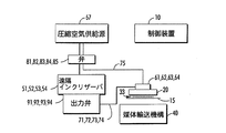
図1及び図3は、制御装置10と、印刷出力媒体15上にインク液滴33を吐出する複数の液滴発生器(液滴吐出器)を具備する印刷ヘッド20と、を備えるインクジェット印刷装置の一例を示す概略ブロック図である。印刷出力媒体輸送機構40は、印刷出力媒体を印刷ヘッド20に対して移動させることができる。印刷ヘッド20は、印刷ヘッド20に取り付けられた複数の内蔵インクリザーバ61、62、63、64からインクを受け取る。各内蔵インクリザーバ61〜64は、複数の遠隔インク容器51、52、53、54からそれぞれのインク供給路71、72、73、74を介してインクを受け取る。
FIGS. 1 and 3 show an inkjet printing apparatus including a
図1〜図3に図示しないが、インクジェット印刷装置は、遠隔インク容器51〜54にインクを供給するためのインク給配システムを備えている。ある実施形態では、インクジェット印刷装置は、相変化インク作像装置である。したがって、インク給配システムは、少なくとも1色の固体形状の相変化インクに関する少なくとも1つの供給源を有する相変化インク給配システムを備える。また、相変化インク給配システムは、固形の相変化インクを液状に溶融又は相変化させ、適切な遠隔インク容器に溶融した相変化インクを給配する溶融装置及び制御装置(図示せず)を備える。
Although not shown in FIGS. 1 to 3, the ink jet printing apparatus includes an ink distribution system for supplying ink to the
遠隔インク容器51〜54は、内部に保持する溶融した相変化インクを内蔵インクリザーバ61〜64に流通させるように構成されている。ある実施形態では、遠隔インク容器51〜54は、例えば、圧縮空気供給源67から複数の弁81、82、83、84を介して供給される圧縮空気によって選択的に加圧される。遠隔インク容器51〜54から内蔵インクリザーバ61〜64へのインクの流れは、例えば、圧力又は重力により実現することができる。出力弁91、92、93、94を内蔵インクリザーバ61〜64へのインクの流れを制御するために設けることができる。用語「遠隔インク容器」又はその均等物は、しばしば説明されるように距離の離間を示すものであるが、その上に機能的関係への適用を意図したものなので、近接した配置、単一のユニットへの一体化又は組付けに対しても同等に適用される。
The
内蔵インクリザーバ61〜64は、例えば、遠隔インク容器51〜54を選択的に加圧し、弁85を介して空気流路75を加圧することにより選択的に加圧される。代替的に、例えば、出力弁91〜94を閉じることによりインク供給路71〜74を閉じて、空気流路75を加圧することもできる。内蔵インクリザーバ61〜64を加圧して、例えば、印刷ヘッド20に関する清掃又はパージ操作を行なうこともできる。内蔵インクリザーバ61〜64及び遠隔インク容器51〜54は、溶融した固形インク(ソリッドインク)を収容するように構成可能であり、かつ加熱機能を有する。インク供給路71〜74及び空気流路75も加熱可能である。
The built-in
内蔵インクリザーバ61〜64は、例えば、弁85を制御して空気流路75を周囲環境雰囲気と通気させることにより通常の印刷動作において周囲環境雰囲気下におかれる。内蔵インクリザーバ61〜64は、遠隔インク容器51〜54からのインクの非加圧移送の間(即ち、内蔵インクリザーバ61〜64を加圧することなくインクを移送する際)、周囲環境雰囲気と通気させることも可能である。
The built-in
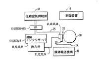
図2は、図1の実施形態と同様であり、かつ印刷ヘッド20により吐出された液滴を受容する転写ドラム30を備えるインクジェット印刷装置の一例を示す概略ブロック図である。印刷出力媒体輸送機構40は、印刷出力媒体15を転写ドラム30と回転係合させ、転写ドラムにプリントされた画像を印刷出力媒体15に転写させる。
FIG. 2 is a schematic block diagram illustrating an example of an inkjet printing apparatus that is similar to the embodiment of FIG. 1 and includes a
図3に概略的に示すように、インク供給路71〜74及び空気流路75の一部分は、マルチコンジットケーブル70のコンジット71A、72A、73A、74A、75Aとして実現することができる。
As schematically shown in FIG. 3, a part of the
図4及び図5は、内蔵インクリザーバ61、62、63、64を実現するリザーバアセンブリ60の一例を示す。リザーバアセンブリ60は、インクタンクとインク供給経路とを内包するハウジングを形成するように組み立てられる複数のプレート又はパネルで形成される。ある実施形態では、リザーバアセンブリは、背面パネル(背面プレート)104と、前面パネル(前面プレート)108と、を備えている。背面パネル104と前面パネル108との間にはフィルタアセンブリ120が配置され、さらに、ヒータ110のシート(ヒータパネル)が第1熱分配プレート114と第2熱分配プレート118との間に挟持される。背面パネル104は、遠隔インク容器51〜54からのインクを受容するリザーバアセンブリ60の後部を構成し、前面パネル108は、印刷ヘッドのインクジェットに供給を行なう内蔵インクリザーバ61〜64を内包するものである。
4 and 5 show an example of a
背面パネル104、第1ヒータプレート114、第2ヒータプレート118、フィルタアセンブリ120、及び前面パネル108は、それぞれステンレス鋼又はアルミニウムなどの熱伝導材料で形成してもよく、例えば、感圧性接着剤又は他の適切な接着剤又は接合剤など適切な様態で相互に接着又は封止してもよい。ヒータ110は、PTC(positive temperature coefficient ;正の温度係数)又はNTC(negative temperature coefficient ;負の温度係数)の材料からなる熱抵抗フィルム、テープ、トレース又はワイヤの形状であってもよく、かつ電流に応じて熱を発生させる加熱要素を備える。加熱要素は、発生した熱を収容された相変化インクを適切な温度に維持又は加熱するのに十分な量だけリザーバアセンブリのプレートに伝達させることが可能な熱特性及び/又は無視できるほど薄い横断面を有するポリイミドなどの絶縁材料により各側面を覆ってもよい。ある実施形態では、ヒータは、リザーバアセンブリ内のインクを摂氏約100度から摂氏約140度の温度範囲内に維持するために、均一な勾配で熱を発生させるように構成される。ヒータ110は、別の温度範囲の熱を発生させるように構成してもよい。ヒータ110は、リザーバアセンブリ内の流路及びチャンバ内で凝固した相変化インクをリザーバアセンブリが溶融させるのに十分な熱を発生させることができる。
The
全体として、インクは、背面パネル104から前面パネル108に向かって移動する。背面パネルは、関連する遠隔インク容器51〜54(図1〜3)からインクを受容するために、供給路71、72、73、74にそれぞれ接続される入力ポート171、172、173、174を備える。ある入力ポートを介して受容されたインクは、近傍に位置する背面プレート及び第1ヒータプレートにより形成されるフィルタチャンバに送られる。図5に示すように、背面パネル104及び/又は第1ヒータプレート114は、フィルタチャンバ124を形成するための凹部、空洞及び/又は壁部を備えてもよい。各フィルタチャンバ124は、入力ポート171〜174の1つ(図5ではポート174)を介してインクを受容するように構成される。垂直フィルタアセンブリ120は、背面パネル104と第1ヒータプレート114との間に挟持され、それらと実質的平行に配置される。フィルタアセンブリは、一般的に、微粒子がインクに紛れ込み噴射プロセスに関する問題を引き起こすことを防止する。微粒子は、ジェットを詰まらせ、故障させるか、又は噴射が軸を外れる可能性がある。垂直フィルタによって印刷ヘッドリザーバをより小型に構成できるが、フィルタは垂直ではなく他の角度で配置することも可能である。また、このフィルタは非常に細密なので、フィルタ全体にわたる圧力低下を抑制するために、フィルタの表面積が最大化される。水平に対してある角度をつけたフィルタにより、その表面積をより大きくできる。フィルタアセンブリのフィルタは、適切な方式で背面パネル及び第1熱分配プレートの一方に接着ないし接合してもよい。別の方法として、フィルタアセンブリのフィルタは、背面パネル及び/又は第1熱分配プレート内の成型又は他の方法で形成されたスロット又は溝などの機構により定位置に保持される。
Overall, ink moves from the
図4及び図5の実施形態では、第1ヒータプレート114は、リザーバアセンブリに組み込まれた各フィルタチャンバ124の上部位置に配された開口271、272、273、274を備える堰板を含む。第1ヒータプレートの開口271〜274は、インク供給経路への入口を構成する。ヒータ110及び第2ヒータプレート118は、残りのインク供給経路を形成するために、第1ヒータプレート/堰板の開口に対応する開口を備える。例えば、図4に示すように、第2ヒータプレート118は、インク経路開口471〜474を備え、ヒータはインク経路開口371〜374を備える。
In the embodiment of FIGS. 4 and 5, the
ヒータ、第1ヒータプレート、及び第2ヒータプレートの開口により形成されたインク供給経路は、本明細書ではタンクプレートと呼ばれる前面パネル108に組み込まれた関連するリザーバ(タンク)61〜64にフィルタチャンバ124に受容されたインクをガイドする。図4に示すように、前面パネルは、第2ヒータプレート118の方向に延び、第2ヒータプレート118と重なって内蔵インクリザーバ61〜64を形成する複数のタンク壁部128を備える。リザーバ61〜64は、印刷ヘッドが作動してインクが射出されるジェットスタックにインクを割り当てるリザーバ61〜64の出口開口を通してインクが排出されるまでインクを保持する。各リザーバは、リザーバの圧力自動調整を可能にする通気孔134を備える。ジェットは、圧力低下を被ることなく流路130を通してインクを吸い込むことができる。さらに、リザーバ通気孔を空気流路75(図1〜図3)に作用可能に連結して、印刷ヘッドに関する清掃又はパージ操作を行なうために、リザーバ61〜64に正圧を導入するようにしてもよい。
The ink supply path formed by the openings of the heater, the first heater plate, and the second heater plate is connected to a filter chamber in associated reservoirs (tanks) 61-64 incorporated in the
図6は、第1熱分配プレート114と第2熱分配プレート118とに接着されたヒータ110と、それぞれのプレート内の整列されたインク供給開口により形成されるインク経路138と、を示している。ヒータ110は、第1サイド140と、第2サイド144と、を有する。第1熱分配プレート114及び第2熱分配プレート118は、ヒータの第1サイド140及び第2サイド144に対する接着(接合)のための接着面148、150をそれぞれ備える。第1及び第2熱分配プレートの接着面は、両面感圧性接着剤(PSA)154を用いてヒータの第1及び第2サイドにそれぞれ接着(接合)されてもよく、その他いかなる適切な接着剤(接合剤)を用いてもよい。この構造により、単一のヒータを用いて実質的にリザーバアセンブリ全体に熱を発生させ、リザーバ内のインクを所望の温度に維持することができる。ヒータ要素自体は、抵抗ヒータ要素から電気的に絶縁された熱伝導材料層を含む様々な層から構成されてもよい。
FIG. 6 shows the
ある実施形態では、ヒータは、絶縁層又は絶縁フィルムの間に挿入された加熱要素層により形成される。図8に示すように、加熱要素層は、インコネルなどの熱伝導材料で形成される抵抗加熱トレース158の蛇行パターンにより形成してもよい。抵抗加熱トレースとして用いられる他の適切な材料には、銅、アルミニウム、銀、様々な合金などが含まれる。ここで、蛇行パターンとは、隣接するスペースにより分離された伝導材料の複数経路を有する任意のトレース配置として定義される。加熱トレースにより発生するワット密度は、加熱トレースの厚さ及び幅だけでなく特定領域内のトレースの形状及び数の関数である。ある実施形態では、加熱トレースのワット密度は、およそ7.75ワット/平方センチメートル(50ワット/平方インチ)であるが、いかなる適切なワット密度を用いてもよい。加熱トレースが所望のワット密度に関して適切に構成された後、各々が延出するワイヤを有する1対の電気パッドが加熱トレースに連結される。これらワイヤの末端はコネクタなので、電流源をワイヤに連結して加熱トレースを通る回線経路を完成させてもよい。この電流により加熱トレースは熱を発生させる。絶縁層又は絶縁フィルムは、ポリイミドなどの適切な熱伝導非導電材料により形成してもよい。熱トレース層は、接着剤(接合剤)などを用いた適切な方式で絶縁層に接着(接合)してもよい。 In certain embodiments, the heater is formed by a heating element layer inserted between insulating layers or films. As shown in FIG. 8, the heating element layer may be formed by a serpentine pattern of resistive heating traces 158 formed of a thermally conductive material such as Inconel. Other suitable materials used as resistive heating traces include copper, aluminum, silver, various alloys, and the like. Here, a meander pattern is defined as any trace arrangement having multiple paths of conductive material separated by adjacent spaces. The watt density generated by a heated trace is a function of not only the thickness and width of the heated trace, but also the shape and number of traces in a particular area. In some embodiments, the watt density of the heating trace is approximately 7.75 watts per square centimeter (50 watts per square inch), but any suitable watt density may be used. After the heating traces are properly configured for the desired watt density, a pair of electrical pads, each having an extending wire, are coupled to the heating traces. Since the ends of these wires are connectors, a current source may be connected to the wires to complete the circuit path through the heating trace. This current causes the heating trace to generate heat. The insulating layer or film may be formed of a suitable heat conducting non-conductive material such as polyimide. The thermal trace layer may be bonded (bonded) to the insulating layer by an appropriate method using an adhesive (bonding agent) or the like.
ヒータ110の局所的な高熱による自壊を防ぐため、ヒータを熱伝導ストリップに連結してヒータの長さに沿った熱の均一性を向上させることができる。熱導体(熱伝導ストリップ)としては、接着された加熱要素層及び絶縁層により形成された構造の少なくとも一方側に接合されたアルミニウム、銅又は他の熱伝導材料の層又はストリップを用いることができる。この熱導体により、高度の熱伝導経路が提供されるので、熱エネルギーが急速かつより均一に拡散する。熱エネルギーの急速な移動により、トレース温度が損傷をもたらす限界より低く保たれ、トレース及びアセンブリの他の構成要素に対する過大な応力が防止される。熱応力が低いと、ヒータ各層の層間剥離につながるトレースの熱的なよじれが少なくなる。他の手段として、有効範囲の領域に対し本質的に均一な加熱を行なうとともに、末端効果や流体流動領域など非均一性に対する局所的な影響を付加的に補償できるPTCフィルムヒータを用いてもよい。
In order to prevent the
図7に、ヒータアセンブリの特定の実施形態に関する材料のスタックが組立分解断面図として層の対応する厚さとともに示されている。ヒータは、アルミ箔160、ポリイミド接着層164、第1ポリイミド168、熱トレース層(インコネル)170、ポリイミド接着層174、及びポリイミド178を順に積層したスタックとして形成されてもよい。図7に示すように、第1ポリイミド絶縁層168は、薄いポリイミド接着層164により箔(アルミ箔160)に接着される。さらに、熱トレース層170が第1絶縁層である第1ポリイミド層168に積層(付着)される。さらに、第2絶縁層である第2ポリイミド層178は、別の薄いポリイミド接着層174を用いて熱トレース層170に接着される。構成されたヒータは、例えば、図6に示すように、PSA接着剤を用いて熱分配プレートに接着されてもよい。図7に示すヒータの材料スタックは、1つの例示的実施形態である。様々な温度環境、ヒータのコスト、又は形状の問題に対処するため、別のヒータ材料、層の構成などを用いてもよい。
In FIG. 7, a stack of materials for a particular embodiment of the heater assembly is shown as an exploded cross-sectional view with the corresponding thickness of the layers. The heater may be formed as a stack in which an
インク供給経路からインクの漏出を防止するために、ヒータと熱分配プレートの接着面との間の接着剤又はシールは、プレートのインク供給経路開口部の周囲において連続していなければならない。第1及び第2熱分配プレートは、例えば、ステンレス鋼又はアルミニウムなどの剛体材料で作成されるので、熱分配プレートの接着面は、少なくとも接着面上のインク供給経路開口を取り囲む領域において、均一又は平面的な形状で形成又は製造してもよい。したがって、インク供給経路開口の周囲におけるヒータ接着面の平坦性ないし平面性は、ヒータと熱分配プレートとの間の接着の有効性にとってきわめて重要である。インク供給経路開口の周囲の領域が、隆起又は陥没領域など非平面表面形状であると、インク供給経路開口周囲におけるヒータと熱分配プレートとの間の接着(接合)が不良となり、インク供給経路に沿って移動するインクがプレート間に滲み出す可能性がある。インクが経時的に供給経路から漏出してヒータと熱分配プレートとの間に達すると、プレート間の接着剤が脆弱化してパージや噴射などの性能低下又は故障が生じることがある。 In order to prevent ink leakage from the ink supply path, the adhesive or seal between the heater and the adhesive surface of the heat distribution plate must be continuous around the ink supply path opening of the plate. Since the first and second heat distribution plates are made of a rigid material such as, for example, stainless steel or aluminum, the bonding surface of the heat distribution plate is uniform or at least in the region surrounding the ink supply path opening on the bonding surface. It may be formed or manufactured in a planar shape. Therefore, the flatness or flatness of the heater bonding surface around the ink supply path opening is extremely important for the effectiveness of bonding between the heater and the heat distribution plate. If the area around the ink supply path opening has a non-planar surface shape such as a raised or depressed area, adhesion (bonding) between the heater and the heat distribution plate around the ink supply path opening becomes poor, and the ink supply path Ink traveling along the plate may ooze between the plates. If the ink leaks from the supply path over time and reaches between the heater and the heat distribution plate, the adhesive between the plates may weaken and performance degradation or failure such as purging or jetting may occur.
トレース方式のヒータ要素の上記例では、ヒータの熱トレース層における熱トレースの蛇行パターン内のトレースブレーク、即ち、トレース間の不連続又はスペースによりヒータのインク供給経路開口周囲の接着領域に非平面表面形状が生じる可能性がある。ヒータは、ヒータ構成層の厚さに対応した全体的厚さを有する。したがって、ヒータの全体的厚さは、トレースが位置するヒータの領域とトレースブレークが位置する領域とで変化することがある。図7の実施形態では、ヒータの全体的厚さは略0.25mmであり、熱トレース層の厚さは略0.025mmである。その結果、ヒータの厚さは、ヒータトレースが位置する領域では0.25mm、トレースブレークが位置する領域では0.175mmであった。 In the above example of a trace-type heater element, a trace break in the serpentine pattern of the thermal trace in the thermal trace layer of the heater, i.e. a non-planar surface in the adhesive area around the heater ink supply path opening due to discontinuities or spaces between the traces Shape may occur. The heater has an overall thickness corresponding to the thickness of the heater component layer. Accordingly, the overall thickness of the heater may vary between the area of the heater where the trace is located and the area where the trace break is located. In the embodiment of FIG. 7, the overall heater thickness is approximately 0.25 mm and the thermal trace layer thickness is approximately 0.025 mm. As a result, the thickness of the heater was 0.25 mm in the region where the heater trace is located, and 0.175 mm in the region where the trace break is located.
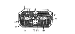
熱トレースパターンの既知の設計では、熱トレースパターンは、図9に示すように、各インク供給経路開口の周囲の領域にトレースブレーク180を有していた。インク供給経路開口371〜374の周囲のトレースブレーク180は、インク供給経路開口371〜374の周囲において対応するヒータ厚さを変化させ、接着に関する非平面表面形状を生じさせる可能性がある。上記のように、ヒータにおけるインク供給経路開口の周囲が非平面表面形状であると、インク供給経路開口の周囲におけるヒータと熱分配プレートとの間の接着(接合)が不良となる可能性がある。 In known designs of thermal trace patterns, the thermal trace patterns had trace breaks 180 in the area around each ink supply path opening, as shown in FIG. Trace breaks 180 around the ink supply path openings 371-374 may change the corresponding heater thickness around the ink supply path openings 371-374, resulting in a non-planar surface shape for adhesion. As described above, if the periphery of the ink supply path opening in the heater has a non-planar surface shape, the adhesion (bonding) between the heater and the heat distribution plate around the ink supply path opening may be poor. .
ヒータの蛇行熱トレース層内におけるトレースブレーク180により生じうるインク供給経路開口の周囲の非平面表面形状による困難に対処するため、熱トレースパターンは、ヒータにおける各インク供給経路開口の周囲にトレースリングを組み込むように修正されてきた。再び図8を参照すると、インク供給経路開口371〜374の周囲のトレースリング184を示す熱トレースパターンの一例が図示されている。トレースリング184は、各インク供給経路開口の周囲の連続した周縁を形成する。トレースリングは、ヒータの熱トレース層の蛇行熱トレースと一体化しており、残りの熱トレースと同じ方式で形成することができる。トレースリングは、残りのヒータトレースと厚さが等しいが、幅は異なってもよく、また、ヒータ回路の一部であるか、或いは機能を果たさないものでもよい。
To address the difficulties due to the non-planar surface shape around the ink supply path openings that can be caused by trace breaks 180 in the serpentine heat trace layer of the heater, the thermal trace pattern has trace rings around each ink supply path opening in the heater. Has been modified to incorporate. Referring again to FIG. 8, an example of a thermal trace pattern showing the
インク供給経路開口を囲むトレースリング184により、インク供給経路開口の周囲におけるヒータの熱トレース層の厚さが一定ないし均一になってヒータ接着面の平面性が増し、インク供給開口周囲のヒータと熱分配プレートとの間の接合が改善される。このようにして、ヒータと熱分配プレートとの間のインク漏出経路を除いてもよい。ワイヤ及び連続、ほぼ連続又は不連続のフィルムを含む他のヒータ要素構成又は材料も、求められる漏出防止アセンブリを容易にするため、ポート開口を囲む均一な厚さに対する同様の注意をもって構成すべきである。
By the
当業者は、上記具体的な実施に対して多くの変更をなしうることを認識するであろう。したがって、特許請求の範囲は、図示及び上記具体的な実施に限定されるべきではない。当初提示された修正可能な特許請求の範囲は、現時点で予見又は予期されず、例えば、出願人/特許権者などから発するものを含む、本明細書で開示される実施形態及び教示の変更、代替、変形、改善、均等物、及び実質的均等物を包含するものである。 Those skilled in the art will recognize that many changes can be made to the specific implementation. Accordingly, the claims should not be limited to the illustrations and specific implementations described above. The originally presented amendable claims are not foreseeable or anticipated at this time, including variations from the embodiments and teachings disclosed herein, including, for example, those originating from the applicant / patentee, etc. Including alternatives, modifications, improvements, equivalents, and substantially equivalents.
10 制御装置、15 印刷出力媒体、20 印刷ヘッド、30 転写ドラム、33 インク液滴、40 印刷出力媒体輸送機構、51、52、53、54 遠隔インク容器、60 リザーバアセンブリ、61、62、63、64 内蔵インクリザーバ、67 圧縮空気供給源、70 マルチコンジットケーブル、71、72、73、74 インク供給路、71A、72A、73A、74A、75A コンジット、75 空気流路、81、82、83、84、85 弁、91、92、93、94 出力弁、104 背面パネル、108 前面パネル、110 ヒータ、114 第1熱分配プレート、118 第2熱分配プレート、120 フィルタアセンブリ、124 フィルタチャンバ、128 タンク壁部、130 流路、134 通気孔、138 インク経路、140 第1サイド、144 第2サイド、148、150 接着面、154 両面感圧性接着剤、158 抵抗加熱トレース、160 アルミ箔、164 ポリイミド接着層、168 第1ポリイミド絶縁層、170 熱トレース層(インコネル)、171、172、173、174 入力ポート、174 ポリイミド接着層、178 第2ポリイミド絶縁層、180 トレースブレーク、184 トレースリング、271、272、273、274 開口、371、372、373、374、471、472、473、474 インク経路開口。 10 controller, 15 print output medium, 20 print head, 30 transfer drum, 33 ink droplet, 40 print output medium transport mechanism, 51, 52, 53, 54 remote ink container, 60 reservoir assembly, 61, 62, 63, 64 Built-in ink reservoir, 67 Compressed air supply source, 70 Multi-conduit cable, 71, 72, 73, 74 Ink supply path, 71A, 72A, 73A, 74A, 75A conduit, 75 Air flow path, 81, 82, 83, 84 , 85 Valve, 91, 92, 93, 94 Output valve, 104 Rear panel, 108 Front panel, 110 Heater, 114 First heat distribution plate, 118 Second heat distribution plate, 120 Filter assembly, 124 Filter chamber, 128 Tank wall Part, 130 flow path, 134 vent hole, 138 ink Road, 140 first side, 144 second side, 148, 150 adhesive surface, 154 double-sided pressure sensitive adhesive, 158 resistance heating trace, 160 aluminum foil, 164 polyimide adhesive layer, 168 first polyimide insulation layer, 170 thermal trace layer (Inconel), 171, 172, 173, 174 input port, 174 polyimide adhesive layer, 178 second polyimide insulating layer, 180 trace break, 184 trace ring, 271, 272, 273, 274 opening, 371, 372, 373, 374 , 471, 472, 473, 474, ink path openings.
Claims (16)
インク供給源から液体インクを受け取るように構成されたインク入力ポートを備える背面プレートと、
前記インク供給源から受け取った前記インクを保持し、プリントヘッドに前記インクを流通させるように構成されたインクタンクを備える前面プレートと、
背面プレートに接着された第1熱分配プレートと、
前面プレートに接着された第2熱分配プレートと、
前記第1及び前記第2熱分配プレートの間に接着されたヒータと、
を備え、
前記ヒータ、前記第1熱分配プレート、及び前記第2熱分配プレートは、それぞれ、前記インク入力ポートから前記インクタンクへ前記インクをガイドするように構成されたインク供給経路を形成するように重なったインク供給経路開口を備え、
前記第1熱分配プレートの接着面、及び前記第2熱分配プレートの接着面は、少なくとも接着面上のインク供給経路開口を取り囲む領域において、均一又は平面的な形状で形成または製造され、
前記ヒータは、
少なくとも前記インク供給経路開口の周囲において均一な厚さを有する第1絶縁層と、
少なくとも前記インク供給経路開口の周囲において均一な厚さを有する第2絶縁層と、
前記第1及び前記第2絶縁層の間に蛇行パターンで配置された抵抗加熱トレースであって、電流に応じて熱を発生するように構成され、上記蛇行パターンの抵抗加熱トレースと同じ厚さを有して一体化され、前記インク供給経路開口の周囲に連続した周縁を形成するトレースリングが組み込まれる抵抗加熱トレースと、
を備え、これによって前記インク供給経路開口の周囲におけるヒータの抵抗加熱トレースの厚さを一定又は均一化することを特徴とするリザーバアセンブリ。 In a reservoir assembly used in a phase change ink imager,
A back plate with an ink input port configured to receive liquid ink from an ink source;
A front plate comprising an ink tank configured to hold the ink received from the ink supply and to circulate the ink through a printhead;
A first heat distribution plate adhered to the back plate;
A second heat distribution plate adhered to the front plate;
A heater bonded between the first and second heat distribution plates;
With
The heater, the first heat distribution plate, and the second heat distribution plate overlap each other to form an ink supply path configured to guide the ink from the ink input port to the ink tank. An ink supply path opening;
The adhesive surface of the first heat distribution plate and the adhesive surface of the second heat distribution plate are formed or manufactured in a uniform or planar shape at least in a region surrounding the ink supply path opening on the adhesive surface,
The heater is
A first insulating layer having a uniform thickness at least around the ink supply path opening;
A second insulating layer having a uniform thickness at least around the ink supply path opening;
A resistance heating trace disposed in a serpentine pattern between the first and second insulating layers, wherein the resistance heating trace is configured to generate heat in response to an electric current , and has the same thickness as the resistance heating trace of the serpentine pattern. are integrated has a resistance heating trace trace rings are incorporated to form the periphery in a continuous periphery of the ink supply path opening,
The reservoir assembly is characterized in that the thickness of the resistance heating trace of the heater around the ink supply path opening is made constant or uniform .
前記第1及び前記第2絶縁層は、ポリイミドを含む材料で形成されることを特徴とするリザーバアセンブリ。 The reservoir assembly of claim 1 , wherein
The reservoir assembly according to claim 1, wherein the first and second insulating layers are made of a material including polyimide.
前記抵抗加熱トレースは、インコネルで形成されることを特徴とするリザーバアセンブリ。 The reservoir assembly of claim 2 , wherein
The reservoir assembly of claim 1, wherein the resistive heating trace is formed of Inconel.
前記ヒータは、さらに、前記第1及び前記第2絶縁層の一方に接着されたアルミ箔層を備えることを特徴とするリザーバアセンブリ。 The reservoir assembly of claim 3 , wherein
The heater assembly further comprises an aluminum foil layer bonded to one of the first and second insulating layers.
前記背面プレートは、複数の前記インク入力ポートを備え、
前記前面プレートは、前記インク入力ポート毎に前記インクタンクを備え、
前記ヒータ、前記第1熱分配プレート、及び前記第2熱分配プレートは、それぞれの前記インク入力ポートから対応する前記インクタンクへ前記インクをガイドするように構成される前記インク供給経路を形成するために前記インク入力ポート毎にインク供給経路開口を備えることを特徴とするリザーバアセンブリ。 The reservoir assembly of claim 4 , wherein
The back plate includes a plurality of the ink input ports,
The front plate includes the ink tank for each ink input port,
The heater, the first heat distribution plate, and the second heat distribution plate form the ink supply path configured to guide the ink from each ink input port to the corresponding ink tank. In addition, an ink supply path opening is provided for each ink input port.
前記抵抗加熱トレースは、前記インク供給経路及び前記インクタンク内に収容された前記インクの溶融状態を維持するための十分な熱を発生させるように構成されていることを特徴とするリザーバアセンブリ。 The reservoir assembly of claim 5 , wherein
The reservoir assembly according to claim 1, wherein the resistance heating trace is configured to generate sufficient heat to maintain a molten state of the ink contained in the ink supply path and the ink tank.
前記抵抗加熱トレースは、前記インク供給経路及び前記インクタンク内に収容された前記インクを100℃から140℃の間に維持するための十分な熱を発生させるように構成されていることを特徴とするリザーバアセンブリ。 The reservoir assembly of claim 6 , wherein
The resistance heating trace is configured to generate sufficient heat to maintain the ink stored in the ink supply path and the ink tank between 100 ° C. and 140 ° C. Reservoir assembly.
前記背面プレート及び前記第1熱分配プレートは、その間のフィルタチャンバを包囲し、
前記フィルタチャンバは、前記インク入力ポートを介して前記インクを受け取り前記第1熱分配プレートの前記インク供給経路開口へ前記インクを割り当てるように構成され、前記インク入力ポートと前記第1熱分配プレートの前記インク供給経路開口との間に配置された少なくとも1つのフィルタを備えることを特徴とするリザーバアセンブリ。 The reservoir assembly of claim 1 , wherein
The back plate and the first heat distribution plate surround a filter chamber therebetween;
The filter chamber is configured to receive the ink via the ink input port and assign the ink to the ink supply path opening of the first heat distribution plate, and the ink input port and the first heat distribution plate A reservoir assembly comprising: at least one filter disposed between the ink supply path opening.
少なくとも1つの第1インク供給経路開口を含み、該第1インク供給経路開口の少なくとも周囲において均一な厚さを有する第1絶縁層と、
前記第1絶縁層の少なくとも1つの前記第1インク供給経路開口と重なる少なくとも1つの第2インク供給経路開口を含み、該第2インク供給経路開口の少なくとも周囲において均一な厚さを有する第2絶縁層と、
を備え、
前記第1及び前記第2絶縁層は、ポリイミドを含む材料から形成され、
前記第1及び前記第2絶縁層の間に配置され、電流を受け取って熱を発生させるように構成され、前記第1及び前記第2インク供給経路開口を囲む抵抗加熱要素であって、均一幅トレース、非均一幅トレース、不連続フィルム、及び連続フィルムからなるグループから選択される構成であり、インコネル、アルミニウム合金、PTC化合物、及びNTC化合物を含むグループから選択される材料で構成される抵抗加熱要素と、
アルミニウム、銅、アルミニウム合金、及び銅合金を含むグループから選択される材料で構成され、前記第1及び前記第2絶縁層の一方に接着され、前記第1及び前記第2インク供給経路開口と重なる少なくとも1つの第3インク供給経路開口を含む箔層と、
を備え、
前記第1絶縁層、前記第2絶縁層、前記抵抗加熱要素、及び前記箔層は、相変化インクリザーバアセンブリの第1及び第2熱分配プレートの間に接着されることを特徴とするヒータ。 A heater used in the reservoir assembly according to claim 1 ,
A first insulating layer including at least one first ink supply path opening and having a uniform thickness at least around the first ink supply path opening;
A second insulation having at least one second ink supply path opening overlapping at least one of the first ink supply path openings of the first insulating layer and having a uniform thickness at least around the second ink supply path opening; Layers,
With
The first and second insulating layers are formed of a material including polyimide,
Wherein the first and disposed between the second insulating layer, is configured to generate heat by receiving a current, a resistance heating element which surrounds the first and the second ink supply path opening, uniform A resistance selected from the group consisting of width traces, non-uniform width traces, discontinuous films, and continuous films, and a resistance selected from a material selected from the group comprising Inconel, aluminum alloys, PTC compounds, and NTC compounds. A heating element;
It is made of a material selected from the group including aluminum, copper, an aluminum alloy, and a copper alloy, is bonded to one of the first and second insulating layers, and overlaps the first and second ink supply path openings. A foil layer including at least one third ink supply path opening;
With
The first insulating layer, the second insulating layer, a heater wherein the resistive heating element, and the foil layer, that will be bonded between the first and second heat distribution plate of a phase change ink reservoir assembly.
前記第1絶縁層は、4つの前記第1インク供給経路開口を含み、
前記第2絶縁層は、4つの前記第2インク供給経路開口を含むことを特徴とするヒータ。 The heater according to claim 9,
The first insulating layer includes four first ink supply path openings,
The heater according to claim 2, wherein the second insulating layer includes four second ink supply path openings.
前記溶融相変化インクを像形成部材に噴出するように構成されたプリントヘッドと、
リザーバアセンブリと、
を備え、
前記リザーバアセンブリは、
前記溶融インク容器から液体インクを受け取るように構成されたインク入力ポートを備える背面プレートと、
前記溶融インク容器から受け取った前記インクを保持し、該インクを前記プリントへッドに流通させるように構成されたインクタンクを備える前面プレートと、
前記背面プレートに接着された第1熱分配プレートと、
前記前面プレートに接着された第2熱分配プレートと、
前記第1及び前記第2熱分配プレートの間に接着されたヒータと、
を備え、
前記ヒータ、前記第1熱分配プレート、及び前記第2熱分配プレートは、それぞれ、前記インク入力ポートから前記インクタンクへ前記インクをガイドするように構成されたインク供給経路を形成するように重なったインク供給経路開口を備え、
前記第1熱分配プレートの接着面、及び前記第2熱分配プレートの接着面は、少なくとも接着面上のインク供給経路開口を取り囲む領域において、均一又は平面的な形状で形成または製造され、
前記ヒータは、
少なくとも前記インク供給経路開口の周囲において均一な厚さを有する第1絶縁層と、
少なくとも前記インク供給経路開口の周囲において均一な厚さを有する第2絶縁層と、
前記第1及び前記第2絶縁層の間に蛇行パターンで配置された抵抗加熱トレースであって、電流に応じて熱を発生するように構成され、上記蛇行パターンの抵抗加熱トレースと同じ厚さを有して一体化され、前記インク供給経路開口の周囲に連続した周縁を形成するトレースリングが組み込まれる抵抗加熱トレースと、
を備え、これによって前記インク供給経路開口の周囲におけるヒータの抵抗加熱トレースの厚さを一定又は均一化することを特徴とするプリンタ。 A molten ink container containing a specific amount of melt phase change ink;
A printhead configured to eject the melt phase change ink to an imaging member;
A reservoir assembly;
With
The reservoir assembly includes
A back plate with an ink input port configured to receive liquid ink from the molten ink container;
A front plate comprising an ink tank configured to hold the ink received from the molten ink container and to distribute the ink through the printhead;
A first heat distribution plate adhered to the back plate;
A second heat distribution plate adhered to the front plate;
A heater bonded between the first and second heat distribution plates;
With
The heater, the first heat distribution plate, and the second heat distribution plate overlap each other to form an ink supply path configured to guide the ink from the ink input port to the ink tank. An ink supply path opening;
The adhesive surface of the first heat distribution plate and the adhesive surface of the second heat distribution plate are formed or manufactured in a uniform or planar shape at least in a region surrounding the ink supply path opening on the adhesive surface,
The heater is
A first insulating layer having a uniform thickness at least around the ink supply path opening;
A second insulating layer having a uniform thickness at least around the ink supply path opening;
A resistance heating trace disposed in a serpentine pattern between the first and second insulating layers, wherein the resistance heating trace is configured to generate heat in response to an electric current , and has the same thickness as the resistance heating trace of the serpentine pattern. are integrated has a resistance heating trace trace rings are incorporated to form the periphery in a continuous periphery of the ink supply path opening,
And the thickness of the resistance heating trace of the heater around the ink supply path opening is made constant or uniform .
前記第1及び前記第2絶縁層は、ポリイミドを含む材料で形成されることを特徴とするプリンタ。 The printer according to claim 11.
The printer according to claim 1, wherein the first and second insulating layers are made of a material containing polyimide.
前記抵抗加熱トレースは、インコネルで形成されることを特徴とするプリンタ。 The printer according to claim 12, wherein
The printer according to claim 1, wherein the resistance heating trace is formed of Inconel.
前記ヒータは、さらに、前記第1及び前記第2絶縁層の一方に接着されたアルミ箔層を備えることを特徴とするプリンタ。 The printer according to claim 13.
The printer further includes an aluminum foil layer bonded to one of the first and second insulating layers.
前記背面プレートは、複数の前記インク入力ポートを備え、
前記前面プレートは、前記インク入力ポート毎に前記インクタンクを備え、
前記ヒータ、前記第1熱分配プレート、及び前記第2熱分配プレートは、それぞれの前記インク入力ポートから対応する前記インクタンクへ前記インクをガイドするように構成される前記インク供給経路を形成するために前記インク入力ポート毎にインク供給経路開口を備えることを特徴とするプリンタ。 The printer according to claim 14.
The back plate includes a plurality of the ink input ports,
The front plate includes the ink tank for each ink input port,
The heater, the first heat distribution plate, and the second heat distribution plate form the ink supply path configured to guide the ink from each ink input port to the corresponding ink tank. An ink supply path opening is provided for each ink input port.
前記抵抗加熱トレースは、前記インク供給経路及び前記インクタンク内に収容された前記インクの溶融状態を維持するための十分な熱を発生させるように構成されていることを特徴とするプリンタ。 The printer according to claim 15, wherein
The printer according to claim 1, wherein the resistance heating trace is configured to generate sufficient heat to maintain a molten state of the ink stored in the ink supply path and the ink tank.
Applications Claiming Priority (2)
| Application Number | Priority Date | Filing Date | Title |
|---|---|---|---|
| US12/355,965 US8092000B2 (en) | 2009-01-19 | 2009-01-19 | Heat element configuration for a reservoir heater |
| US12/355,965 | 2009-01-19 |
Publications (3)
| Publication Number | Publication Date |
|---|---|
| JP2010162895A JP2010162895A (en) | 2010-07-29 |
| JP2010162895A5 JP2010162895A5 (en) | 2013-02-21 |
| JP5280382B2 true JP5280382B2 (en) | 2013-09-04 |
Family
ID=42115956
Family Applications (1)
| Application Number | Title | Priority Date | Filing Date |
|---|---|---|---|
| JP2010005240A Expired - Fee Related JP5280382B2 (en) | 2009-01-19 | 2010-01-13 | Reservoir assembly, heater and printer |
Country Status (7)
| Country | Link |
|---|---|
| US (2) | US8092000B2 (en) |
| EP (1) | EP2208619B1 (en) |
| JP (1) | JP5280382B2 (en) |
| KR (1) | KR101544227B1 (en) |
| CN (1) | CN101856908B (en) |
| BR (1) | BRPI1000119A2 (en) |
| MX (1) | MX2010000538A (en) |
Families Citing this family (10)
| Publication number | Priority date | Publication date | Assignee | Title |
|---|---|---|---|---|
| US8313183B2 (en) * | 2010-11-05 | 2012-11-20 | Xerox Corporation | Immersed high surface area heater for a solid ink reservoir |
| US9123756B2 (en) * | 2011-08-30 | 2015-09-01 | Watlow Electric Manufacturing Company | System and method for controlling a thermal array |
| JP5870691B2 (en) * | 2011-12-28 | 2016-03-01 | セイコーエプソン株式会社 | Liquid ejector |
| US8864293B2 (en) * | 2012-09-12 | 2014-10-21 | Xerox Corporation | Phase change ink reservoir for a phase change inkjet printer |
| US9457574B2 (en) | 2013-12-23 | 2016-10-04 | Palo Alto Research Center Incorporated | Process to fabricate an injection molded printhead with inkjet nozzle face plate |
| US9205663B2 (en) | 2014-03-26 | 2015-12-08 | Palo Alto Research Center Incorporated | Inkjet print heads with inductive heating |
| US9238365B1 (en) | 2014-08-07 | 2016-01-19 | Xerox Corporation | Flex circuit board with topographical structures to facilitate fluid flow through the layer |
| WO2016056450A1 (en) * | 2014-10-10 | 2016-04-14 | コニカミノルタ株式会社 | Ink heating device and inkjet recording device |
| US10842667B2 (en) * | 2016-02-17 | 2020-11-24 | Tramec Termico Technologies, L.L.C. | Self-regulating heater |
| JP7346826B2 (en) * | 2019-01-24 | 2023-09-20 | 京セラドキュメントソリューションズ株式会社 | Head unit and inkjet recording device |
Family Cites Families (9)
| Publication number | Priority date | Publication date | Assignee | Title |
|---|---|---|---|---|
| US5635964A (en) * | 1995-01-18 | 1997-06-03 | Tektronix, Inc. | Ink-jet print head having improved thermal uniformity |
| US6239820B1 (en) * | 1995-12-06 | 2001-05-29 | Hewlett-Packard Company | Thin-film printhead device for an ink-jet printer |
| JP4399064B2 (en) * | 1999-10-21 | 2010-01-13 | 株式会社コーナン・メディカル | Ink container for marking device |
| US6704996B2 (en) * | 2002-04-30 | 2004-03-16 | Lexmark International, Inc. | Method for making ink jet printheads |
| JP2007511052A (en) * | 2003-11-07 | 2007-04-26 | セレリティ・インコーポレイテッド | Surface mount heater |
| US7011399B2 (en) * | 2004-01-05 | 2006-03-14 | Xerox Corporation | Low thermal mass, variable watt density formable heaters for printer applications |
| KR100657950B1 (en) * | 2005-02-05 | 2006-12-14 | 삼성전자주식회사 | Ink supply apparatus and ink-jet printhead package having the same |
| US7413299B2 (en) * | 2005-03-15 | 2008-08-19 | Xerox Corporation | Pressurizing a heatable printhead while it cools |
| US7300143B2 (en) * | 2005-04-05 | 2007-11-27 | Xerox Corporation | Ink jet apparatus |
-
2009
- 2009-01-19 US US12/355,965 patent/US8092000B2/en not_active Expired - Fee Related
-
2010
- 2010-01-13 JP JP2010005240A patent/JP5280382B2/en not_active Expired - Fee Related
- 2010-01-13 MX MX2010000538A patent/MX2010000538A/en active IP Right Grant
- 2010-01-15 KR KR1020100003726A patent/KR101544227B1/en active IP Right Grant
- 2010-01-19 CN CN201010104812.2A patent/CN101856908B/en not_active Expired - Fee Related
- 2010-01-19 EP EP10151071A patent/EP2208619B1/en not_active Not-in-force
- 2010-01-19 BR BRPI1000119-0A patent/BRPI1000119A2/en not_active IP Right Cessation
-
2012
- 2012-01-09 US US13/346,142 patent/US8550611B2/en active Active
Also Published As
| Publication number | Publication date |
|---|---|
| BRPI1000119A2 (en) | 2011-03-29 |
| KR20100084982A (en) | 2010-07-28 |
| US8550611B2 (en) | 2013-10-08 |
| MX2010000538A (en) | 2010-07-19 |
| KR101544227B1 (en) | 2015-08-12 |
| US20120113196A1 (en) | 2012-05-10 |
| US20100182386A1 (en) | 2010-07-22 |
| EP2208619A1 (en) | 2010-07-21 |
| CN101856908B (en) | 2014-12-31 |
| CN101856908A (en) | 2010-10-13 |
| JP2010162895A (en) | 2010-07-29 |
| US8092000B2 (en) | 2012-01-10 |
| EP2208619B1 (en) | 2012-10-24 |
Similar Documents
| Publication | Publication Date | Title |
|---|---|---|
| JP5280382B2 (en) | Reservoir assembly, heater and printer | |
| JP4976272B2 (en) | Heated ink delivery system | |
| JP5094892B2 (en) | Foam plate to reduce foam in print head | |
| JP2832576B2 (en) | Temperature holding device and method | |
| TWI221811B (en) | Thermal inkjet printer having enhanced heat removal capability and method of assembling the printer | |
| US8313183B2 (en) | Immersed high surface area heater for a solid ink reservoir | |
| JP5213367B2 (en) | Inkjet recording head | |
| US7843476B2 (en) | Thermal head and printer | |
| JP4523436B2 (en) | Inkjet printer temperature control base, inkjet printer head with temperature control function, and inkjet printer | |
| EP3299172B1 (en) | Ink jet head | |
| US8038281B2 (en) | Media preheater | |
| US20180072052A1 (en) | Ink jet head | |
| US20080317536A1 (en) | Printer apparatus | |
| JP2004223878A (en) | Liquid ejecting head and liquid ejector | |
| JPH0199849A (en) | Color ink jet recorder | |
| JP2009233903A (en) | Liquid jet head and liquid jet apparatus |
Legal Events
| Date | Code | Title | Description |
|---|---|---|---|
| A521 | Request for written amendment filed |
Free format text: JAPANESE INTERMEDIATE CODE: A523 Effective date: 20130104 |
|
| A621 | Written request for application examination |
Free format text: JAPANESE INTERMEDIATE CODE: A621 Effective date: 20130104 |
|
| A871 | Explanation of circumstances concerning accelerated examination |
Free format text: JAPANESE INTERMEDIATE CODE: A871 Effective date: 20130104 |
|
| A975 | Report on accelerated examination |
Free format text: JAPANESE INTERMEDIATE CODE: A971005 Effective date: 20130125 |
|
| A131 | Notification of reasons for refusal |
Free format text: JAPANESE INTERMEDIATE CODE: A131 Effective date: 20130205 |
|
| A521 | Request for written amendment filed |
Free format text: JAPANESE INTERMEDIATE CODE: A523 Effective date: 20130416 |
|
| TRDD | Decision of grant or rejection written | ||
| A01 | Written decision to grant a patent or to grant a registration (utility model) |
Free format text: JAPANESE INTERMEDIATE CODE: A01 Effective date: 20130514 |
|
| A61 | First payment of annual fees (during grant procedure) |
Free format text: JAPANESE INTERMEDIATE CODE: A61 Effective date: 20130522 |
|
| R150 | Certificate of patent or registration of utility model |
Free format text: JAPANESE INTERMEDIATE CODE: R150 Ref document number: 5280382 Country of ref document: JP Free format text: JAPANESE INTERMEDIATE CODE: R150 |
|
| R250 | Receipt of annual fees |
Free format text: JAPANESE INTERMEDIATE CODE: R250 |
|
| R250 | Receipt of annual fees |
Free format text: JAPANESE INTERMEDIATE CODE: R250 |
|
| R250 | Receipt of annual fees |
Free format text: JAPANESE INTERMEDIATE CODE: R250 |
|
| LAPS | Cancellation because of no payment of annual fees |