JP5094892B2 - Foam plate to reduce foam in print head - Google Patents
Foam plate to reduce foam in print head Download PDFInfo
- Publication number
- JP5094892B2 JP5094892B2 JP2010021046A JP2010021046A JP5094892B2 JP 5094892 B2 JP5094892 B2 JP 5094892B2 JP 2010021046 A JP2010021046 A JP 2010021046A JP 2010021046 A JP2010021046 A JP 2010021046A JP 5094892 B2 JP5094892 B2 JP 5094892B2
- Authority
- JP
- Japan
- Prior art keywords
- ink
- plate
- supply path
- ink supply
- reservoir
- Prior art date
- Legal status (The legal status is an assumption and is not a legal conclusion. Google has not performed a legal analysis and makes no representation as to the accuracy of the status listed.)
- Expired - Fee Related
Links
Images


Classifications
-
- B—PERFORMING OPERATIONS; TRANSPORTING
- B41—PRINTING; LINING MACHINES; TYPEWRITERS; STAMPS
- B41J—TYPEWRITERS; SELECTIVE PRINTING MECHANISMS, i.e. MECHANISMS PRINTING OTHERWISE THAN FROM A FORME; CORRECTION OF TYPOGRAPHICAL ERRORS
- B41J2/00—Typewriters or selective printing mechanisms characterised by the printing or marking process for which they are designed
- B41J2/005—Typewriters or selective printing mechanisms characterised by the printing or marking process for which they are designed characterised by bringing liquid or particles selectively into contact with a printing material
- B41J2/01—Ink jet
- B41J2/17—Ink jet characterised by ink handling
- B41J2/175—Ink supply systems ; Circuit parts therefor
- B41J2/17593—Supplying ink in a solid state
-
- B—PERFORMING OPERATIONS; TRANSPORTING
- B41—PRINTING; LINING MACHINES; TYPEWRITERS; STAMPS
- B41J—TYPEWRITERS; SELECTIVE PRINTING MECHANISMS, i.e. MECHANISMS PRINTING OTHERWISE THAN FROM A FORME; CORRECTION OF TYPOGRAPHICAL ERRORS
- B41J2/00—Typewriters or selective printing mechanisms characterised by the printing or marking process for which they are designed
- B41J2/005—Typewriters or selective printing mechanisms characterised by the printing or marking process for which they are designed characterised by bringing liquid or particles selectively into contact with a printing material
- B41J2/01—Ink jet
- B41J2/17—Ink jet characterised by ink handling
- B41J2/175—Ink supply systems ; Circuit parts therefor
- B41J2/17503—Ink cartridges
- B41J2/17506—Refilling of the cartridge
- B41J2/17509—Whilst mounted in the printer
-
- B—PERFORMING OPERATIONS; TRANSPORTING
- B41—PRINTING; LINING MACHINES; TYPEWRITERS; STAMPS
- B41J—TYPEWRITERS; SELECTIVE PRINTING MECHANISMS, i.e. MECHANISMS PRINTING OTHERWISE THAN FROM A FORME; CORRECTION OF TYPOGRAPHICAL ERRORS
- B41J2/00—Typewriters or selective printing mechanisms characterised by the printing or marking process for which they are designed
- B41J2/005—Typewriters or selective printing mechanisms characterised by the printing or marking process for which they are designed characterised by bringing liquid or particles selectively into contact with a printing material
- B41J2/01—Ink jet
- B41J2/17—Ink jet characterised by ink handling
- B41J2/175—Ink supply systems ; Circuit parts therefor
- B41J2/17503—Ink cartridges
- B41J2/17513—Inner structure
-
- B—PERFORMING OPERATIONS; TRANSPORTING
- B41—PRINTING; LINING MACHINES; TYPEWRITERS; STAMPS
- B41J—TYPEWRITERS; SELECTIVE PRINTING MECHANISMS, i.e. MECHANISMS PRINTING OTHERWISE THAN FROM A FORME; CORRECTION OF TYPOGRAPHICAL ERRORS
- B41J2/00—Typewriters or selective printing mechanisms characterised by the printing or marking process for which they are designed
- B41J2/005—Typewriters or selective printing mechanisms characterised by the printing or marking process for which they are designed characterised by bringing liquid or particles selectively into contact with a printing material
- B41J2/01—Ink jet
- B41J2/17—Ink jet characterised by ink handling
- B41J2/175—Ink supply systems ; Circuit parts therefor
- B41J2/17596—Ink pumps, ink valves
-
- B—PERFORMING OPERATIONS; TRANSPORTING
- B41—PRINTING; LINING MACHINES; TYPEWRITERS; STAMPS
- B41J—TYPEWRITERS; SELECTIVE PRINTING MECHANISMS, i.e. MECHANISMS PRINTING OTHERWISE THAN FROM A FORME; CORRECTION OF TYPOGRAPHICAL ERRORS
- B41J2/00—Typewriters or selective printing mechanisms characterised by the printing or marking process for which they are designed
- B41J2/005—Typewriters or selective printing mechanisms characterised by the printing or marking process for which they are designed characterised by bringing liquid or particles selectively into contact with a printing material
- B41J2/01—Ink jet
- B41J2/17—Ink jet characterised by ink handling
- B41J2/19—Ink jet characterised by ink handling for removing air bubbles
Abstract
Description
本開示は、一般に、相変化インクジェット画像形成装置に関し、具体的には、こうした画像形成装置で用いられるプリントヘッドにおける泡を減少させるための方法及び装置に関する。 The present disclosure relates generally to phase change ink jet imaging devices, and in particular to methods and apparatus for reducing bubbles in print heads used in such imaging devices.
固形インク又は相変化インクプリンタは、通常、ペレット又はインクスティックのいずれかで、固体形態のインクを受け取る。固形インクのペレット又はインクスティックは、典型的には、プリンタのインク・ローダの挿入開口部を通して挿入され、インクスティックは、給送機構及び/又は重力により、給送チャネルに沿って、固形インク溶融組立体の方向に押し込まれる又は滑らされる。溶融組立体は、固形インクを溶融して液体にし、その液体は、溶融インク容器に送給される。溶融インク容器は、ある量の溶融インクを保持し、かつ、必要に応じて、溶融インクをプリンタの少なくとも1つのプリントヘッドに近接して配置された1つ又はそれ以上のプリントヘッド・リザーバに伝えるように構成される。この溶融インク容器は、該溶融インク容器とプリントヘッドとの間の溶融組立体上に配置することができ、又は、ヘッド・リザーバの一部とすることができる。 Solid ink or phase change ink printers typically receive ink in solid form, either in pellets or ink sticks. Solid ink pellets or ink sticks are typically inserted through the insertion opening of the printer's ink loader, and the ink stick is melted along the feed channel by the feed mechanism and / or gravity. It is pushed or slid in the direction of the assembly. The melting assembly melts the solid ink into a liquid that is delivered to the molten ink container. The molten ink container holds a quantity of molten ink and optionally conveys the molten ink to one or more printhead reservoirs located proximate to at least one printhead of the printer. Configured as follows. The molten ink container can be placed on the melt assembly between the molten ink container and the printhead, or can be part of the head reservoir.
一部の印刷システムにおいて、遠隔インク容器は、インク容器とプリントヘッド・リザーバとの間に延びるインク送給導管又はチューブを通して、内部に保持される溶融相変化インクをプリントヘッド・リザーバに伝えるように構成される。インク容器内に正圧を導入して、容器内のインクが送給導管に入り、プリントヘッド・リザーバに移動するようにすることにより、インクは、インク送給導管を通して送出される。加圧インクがプリントヘッド・リザーバに到達すると、加圧インクは、典型的には、インクが保持されるオンボード・チャンバ又は槽に達する前に、フィルタに通され、必要に応じて、プリントヘッドのインクジェットに送給される。 In some printing systems, the remote ink container communicates melt phase change ink retained therein to the printhead reservoir through an ink delivery conduit or tube extending between the ink container and the printhead reservoir. Composed. Ink is delivered through the ink delivery conduit by introducing positive pressure into the ink reservoir so that the ink in the container enters the delivery conduit and moves to the printhead reservoir. When the pressurized ink reaches the printhead reservoir, the pressurized ink is typically passed through a filter before reaching the onboard chamber or reservoir where the ink is held, and if necessary, the printhead To the inkjet.
溶融相変化インクをプリントヘッド・リザーバに伝えるために加圧インク送給を用いる際に直面する1つの問題は、プリントヘッド・リザーバにおける泡の形成である。例えば、プリンタがオフにされたとき又はスリープ・モードに入ったとき、インク容器、導管、及びプリントヘッド・リザーバ内に残っている溶融インクが固化又は凝固することがある。その後再びプリンタの電源が入れられたとき又はスリープ・モードから復帰したとき、インクの液の中に存在した空気が液から出て、インク容器、導管、及びプリントヘッド・リザーバ内に気泡又は空気ポケットを形成することがある。加圧インクを送給する際、インク容器、導管、及びプリントヘッド・リザーバ内に閉じ込められた空気は、溶融インクと共に、プリントヘッド・リザーバ・フィルタを通して押し出され、泡を生じさせることがある。泡は、3つの問題をもたらす。すなわち、1)泡は、プリントヘッドのオンボード・インク槽の名目最大液体インク・レベルより上の容積を完全に満たし、色混合及び/又は通気ラインの詰まりをもたらす、2)泡が液体インクよりも大きい容積を占めるため、泡は、レベル感知プローブにおいて「満杯」という間違った指示値をもたらすことがある、3)泡は、インクジェットに至るインク流路において同伴される可能性が高く、典型的には、断続的脆弱・消失ジェット(Intermittent Weak and Missing jets、IWM)と呼ばれる、インクジェットの機能不良を引き起こすことがある。 One problem encountered when using pressurized ink delivery to convey melt phase change ink to the printhead reservoir is the formation of bubbles in the printhead reservoir. For example, when the printer is turned off or enters sleep mode, the molten ink remaining in the ink container, conduit, and printhead reservoir may solidify or solidify. When the printer is turned on again or resumes from sleep mode, the air that was present in the ink liquid exits the liquid and bubbles or air pockets in the ink container, conduit, and printhead reservoir May form. When delivering pressurized ink, air trapped within the ink container, conduit, and printhead reservoir may be forced through the printhead reservoir filter with the molten ink, creating bubbles. Bubbles cause three problems. That is, 1) the foam completely fills the volume above the nominal maximum liquid ink level of the on-board ink reservoir of the printhead, resulting in color mixing and / or clogging of the vent line, 2) the foam is more than liquid ink The foam may give the wrong indication of “full” in the level sensing probe, 3) the foam is likely to be entrained in the ink flow path leading to the inkjet and is typical May cause a malfunction of the ink jet called Intermittent Weak and Missing Jets (IWM).
別の実施形態においては、相変化インク画像形成装置で用いるためのリザーバ組立体が、インク供給源から液体インクを受け取るように構成されたインク入口ポートを含む背面プレートと、インク供給源から受け取ったインクを保持し、インクをプリントヘッドに伝えるように構成されたインク槽を含む前面プレートとを含む。泡プレートが、前面プレートと背面プレートとの間に配置される。泡プレート及び背面プレートは、これらの間にフィルタ・チャンバを囲む。フィルタ・チャンバは、インク入口ポートを介してインクを受け取るように構成され、泡プレートは、フィルタ・チャンバからインク槽へのインク泡の流れを抑制するように構成されたスリットを出る薄いチャンバを含み、従って、泡の大部分が潰される。フィルタ・チャンバは、インク入口ポートと泡プレート内のスリットとの間に配置された少なくとも1つのフィルタを含む。 In another embodiment, a reservoir assembly for use in a phase change ink imaging device is received from an ink source and a back plate that includes an ink inlet port configured to receive liquid ink from the ink source. And a front plate including an ink reservoir configured to hold ink and convey ink to the printhead. A foam plate is disposed between the front plate and the back plate. A foam plate and a back plate surround the filter chamber between them. The filter chamber is configured to receive ink through an ink inlet port, and the foam plate includes a thin chamber exiting a slit configured to inhibit the flow of ink bubbles from the filter chamber to the ink reservoir. Therefore, most of the foam is crushed. The filter chamber includes at least one filter disposed between the ink inlet port and a slit in the foam plate.
本開示の前述の態様及び他の特徴が、添付の図面と併せて以下の説明に記載される。 The foregoing aspects and other features of the disclosure are described in the following description, taken in conjunction with the accompanying drawings.
ここで用いられる「画像形成装置」という用語は、一般に、画像を印刷媒体に適用するための装置を指す。「印刷媒体」は、事前に切断されたものであろうと、又はウェブ状で給送されたものであろうと、薄い物理的な紙、プラスチック、或いは画像に適した他の物理的な印刷媒体基材とすることができる。画像形成装置は、仕上げ機、給紙機等といった種々の他のコンポーネントを含むことができ、コピー機、プリンタ、又は多機能機械として具体化することができる。「印刷ジョブ」又は「文書」とは、通常は、特定のユーザからの、1組のオリジナルの印刷ジョブシート又は電子文書ページ画像からコピーされた1つ又はそれ以上の丁合いされたコピーの組であるか、或いは別の方法により関連された、1組の関連するシートである。画像は、一般に、マーキングエンジンにより印刷媒体上にレンダリングされる電子形態の情報を含むことができ、テキスト、グラフィックス、絵等を含むことができる。 The term “image forming apparatus” as used herein generally refers to an apparatus for applying an image to a print medium. “Print media”, whether pre-cut or web-fed, is a thin physical paper, plastic, or other physical print media substrate suitable for images. It can be a material. The image forming apparatus can include various other components, such as a finisher, a paper feeder, etc., and can be embodied as a copier, printer, or multifunction machine. A “print job” or “document” is typically a set of one or more collated copies copied from a set of original print job sheets or electronic document page images from a particular user. Or a set of related sheets related by another method. An image generally can include information in electronic form that is rendered on a print medium by a marking engine, and can include text, graphics, pictures, and the like.
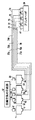
図1及び図3は、コントローラ10と、プリントヘッド20とを含むインクジェット印刷装置の実施形態の概略的なブロック図であり、プリントヘッド20は、インク33の液滴を印刷出力媒体15上に放出するための複数の液滴放出液滴生成器を含むことができる。印刷出力媒体搬送機構40が、印刷出力媒体をプリントヘッド20に対して動かすことができる。プリントヘッド20は、このプリントヘッド20に取り付けられた複数のオンボード・インク・リザーバ61、62、63、64からインクを受け取る。オンボード・インク・リザーバ61−64は、それぞれ、それぞれのインク供給チャネル71、72、73、74を介して、複数の遠隔インク容器51、52、53、54からインクを受け取る。
FIGS. 1 and 3 are schematic block diagrams of an embodiment of an ink jet printing apparatus that includes a
インクジェット印刷装置は、インクを遠隔インク容器51−54に供給するためのインク送給システム(図1−図3には図示されていない)を含む。一実施形態においては、インクジェット印刷装置は、相変化インク画像形成装置である。従って、インク送給システムは、固形状態の相変化インクの少なくとも1つのカラーの少なくとも1つの供給源を有する相変化インク送給システムを含む。相変化インク送給システムはまた、固形状態の相変化インクを溶融又は相変化させて液状にし、溶融した相変化インクを適切な遠隔インク容器に給送するための溶融・制御装置(図示せず)も含む。 The ink jet printing apparatus includes an ink delivery system (not shown in FIGS. 1-3) for supplying ink to the remote ink containers 51-54. In one embodiment, the ink jet printing device is a phase change ink image forming device. Accordingly, the ink delivery system includes a phase change ink delivery system having at least one source of at least one color of solid state phase change ink. The phase change ink delivery system also melts or phase changes the solid phase change ink into a liquid and a melt and control device (not shown) for delivering the melted phase change ink to a suitable remote ink container. ) Is also included.
遠隔インク容器51−54は、内部に保持される溶融相変化インクをオンボード・インク・リザーバ61−64に伝えるように構成される。一実施形態においては、例えば、複数の弁81、82、83、84を介して、加圧空気供給源67により与えられる加圧空気によって、遠隔インク容器51−54を選択的に加圧することができる。遠隔容器51−54からオンボード・リザーバ61−64へのインクの流れは、例えば、圧力又は重力によるものとすることができる。出力弁91、92、93、94を設けて、オンボード・インク・リザーバ61−64へのインクの流れを制御することができる。
The remote ink containers 51-54 are configured to convey the melt phase change ink retained therein to the onboard ink reservoirs 61-64. In one embodiment, the remote ink containers 51-54 can be selectively pressurized with pressurized air provided by a
オンボード・インク・リザーバ61−64はまた、例えば、遠隔インク容器51−54を選択的に加圧し、弁85を介して空気チャネル75を加圧することによっても、選択的に加圧することができる。或いは、インク供給チャンネル71−74を、例えば、出力弁91−94を閉じることによって閉鎖し、空気チャネル75を加圧することができる。オンボード・インク・リザーバ61−64を加圧して、例えば、プリントヘッド20における洗浄動作又はパージ動作を行なうことができる。オンボード・インク・リザーバ61−64及び遠隔インク容器51−54は、溶融固体インクを含有するように構成することができ、加熱することができる。インク供給チャンネル71−74及び空気チャネル75を加熱することもできる。
On-board ink reservoirs 61-64 can also be selectively pressurized, for example, by selectively pressurizing remote ink containers 51-54 and pressurizing
オンボード・インク・リザーバ61−64は、通常の印刷動作中、例えば、弁85を制御して、空気チャネル75を大気に通気することによって、大気に通気される。オンボード・インク・リザーバ61−64はまた、遠隔インク容器51−54からのインクの非加圧転写中(すなわち、オンボード・インク・リザーバ61−64を加圧することなくインクが転写される場合)に大気に通気することもできる。
Onboard ink reservoirs 61-64 are vented to the atmosphere during normal printing operations, for example, by controlling
図2は、図1の実施形態に類似しており、プリントヘッド20により放出された液滴を受け取るための転写ドラム30を含むインクジェット印刷装置の実施形態の概略的なブロック図である。印刷出力媒体搬送機構40は、転写ドラム30に対して、出力印刷媒体15と回転係合して、転写ドラム上に印刷された画像が印刷出力媒体15に転写されるようにする。
FIG. 2 is a schematic block diagram of an embodiment of an inkjet printing apparatus that is similar to the embodiment of FIG. 1 and includes a
図3に概略的に示すように、インク供給チャンネル71−74及び空気チャネル75の一部を、多導管ケーブル70における導管71A、72A、73A、74A、75Aとして実装することができる。
As shown schematically in FIG. 3, a portion of ink supply channels 71-74 and
加圧されたインクがプリントヘッドのオンボード・リザーバに到達すると、加圧インクは、印刷媒体(図1)、又は転写ドラム30(図2)のような中間転写部材上に噴出するためにインクをインクジェットに伝えるように構成されたオンボード・リザーバ内のチャンバ又は槽内に集められる前に、フィルタに通される。上述のように、電源投入又はスリープ・モードからの復帰といった過渡状態において、閉じ込められた空気は、溶融インクと共にオンボード・リザーバ内のフィルタを通して押し出されて泡を形成し、泡によりオンボード・リザーバのインク槽又はチャンバがいっぱいになり、インクの色が混合し、空気経路が詰まることがある。泡により、槽又はチャネル内のインク・レベル・センサが、インク・レベルを読み違えること又は誤った解釈をすること、及び/又は、プリントヘッドのインクジェットを部分的に又は完全に阻止することもあり、断続的脆弱・消失ジェット(IWM)をもたらす。 When the pressurized ink reaches the on-board reservoir of the printhead, the pressurized ink is ejected onto a print medium (FIG. 1) or an intermediate transfer member such as the transfer drum 30 (FIG. 2). Before being collected in a chamber or tub in an on-board reservoir configured to communicate to the inkjet. As described above, in transient conditions such as power-up or return from sleep mode, trapped air is pushed out with the molten ink through a filter in the on-board reservoir to form a bubble, which causes the on-board reservoir to Ink tanks or chambers can fill, mix ink colors, and block the air path. Bubbles can cause the ink level sensor in the reservoir or channel to misread or misinterpret the ink level and / or partially or completely block the printhead inkjet. , Resulting in intermittent vulnerability and vanishing jets (IWM).
リザーバ・フィルタを通して加圧インクを送給することにより引き起こされる、プリントヘッド・リザーバにおける泡形成を減少させる又は排除するために、本開示は、オンボード・リザーバ61、62、63、64を実装するために用いることができ、かつ、泡がリザーバ組立体のインク槽に入る前に、泡を構成する気泡を潰し、圧縮し、引き伸ばし、及び/又は剪断するように設計された、リザーバ・フィルタとオンボード・リザーバのインク槽又はチャンバとの間の一連の泡減少通路、開口部、又は経路を提供する、リザーバ組立体を提案する。泡減少経路は、フィルタとオンボード・リザーバのインク槽との間にリザーバ組立体を構成するプレート内の構造部により形成することができ、かつ、泡がリザーバ槽に到達する前に、インク供給経路に入る泡を構成する気泡を、潰し、圧縮し、引き伸ばし、及び/又は剪断することを可能にする少なくとも1つの特徴を有する。泡減少経路が、該経路に入る泡の中の気泡を潰し、及び/又は剪断するのを可能にする特徴の例として、アスペクト比を変更すること、インク/泡が経路に沿って移動するときに経路の断面積を減少させること、及び経路に沿った相対的に鋭利な縁部が挙げられる。さらに、本説明は、主として、相変化インク画像形成装置のプリントヘッド・リザーバ組立体における泡減少インク通路の利用に向けられるが、こうした泡減少通路を用いて、例えば、水性インク、油性インク、UV硬化インク等のような他の形態のマーキング材料を用いるプリントヘッドにおける泡の形成を減少させること又は防止することもできる。従って、ここで利用される相変化インク及び相変化インク・プリントヘッドへの言及は、どのような形でも本開示を制限するように解釈すべきではない。
To reduce or eliminate foam formation in the printhead reservoir caused by pumping pressurized ink through the reservoir filter, the present disclosure implements
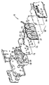
図4及び図5は、オンボード・リザーバ61、62、63、64を実装するためのリザーバ組立体60の実施形態を示す。リザーバ組立体60は、インク槽及びインク供給経路を収容するハウジングを形成するよう組み立てられた複数のプレート又はパネルで形成される。1つの実施形態においては、リザーバ組立体は、背面パネル又はプレート104と、前面パネル又はプレート108とを含む。背面パネル104と前面パネル108との間には、フィルタ組立体120が配置され、次いで、ヒータ・シート又はパネル110が、第1の熱分配プレート114と第2の熱分配プレート118に挟まれている。背面パネル104は、通常、遠隔インク容器51−54からインクを受け取るリザーバ組立体60の後部を構成し、前面パネル108は、プリントヘッドのインクジェットを給送するリザーバ61−64を含む。
4 and 5 show an embodiment of a
ヒータ110は、そこを通って流れる電流に応答して熱を生成する、抵抗熱テープ、トレース、又はワイヤの形態とすることができる加熱素子を含む。加熱素子は、内部に含まれる相変化インクを適切な温度に維持する又は加熱するために、生成された熱を適切な量でリザーバ組立体のプレートに伝達するのを可能にする熱的性質を有する電気絶縁で両側を覆うことができる。1つの実施形態においては、ヒータ110は、下記により詳細に説明される方法で作られるカプトン・ヒータである。異なる温度環境のために、又は、アンビリカル組立体の他の実施形態の構成についてのコスト及び幾何学的形状の問題に対処するために、シリコン・ヒータのような代替的なヒータ材料及び構成を用いることもできる。
The
背面プレート104、第1のヒータ・プレート114、第2のヒータ・プレート118、フィルタ組立体120、及び前面プレート108の各々は、ステンレス鋼又はアルミニウムなどの熱伝導材料で形成することができ、例えば感圧接着剤又は他の好適な接着剤又は結合剤などにより、任意の好適な方法で互いに接合又は封止することができる。ヒータ110は、そこを通って流れる電流に応答して熱を生成する、抵抗熱テープ、トレース、又はワイヤの形態とすることができる加熱素子を含む。加熱素子は、内部に含まれる相変化インクを適切な温度に維持する又は加熱するために、生成された熱を適切な量でリザーバ組立体のプレートに伝達するのを可能にする熱的性質を有する、ポリイミドのような電気絶縁材料で両側を覆うことができる。1つの実施形態においては、ヒータは、リザーバ組立体内のインクを約摂氏100度から約摂氏140度までの温度範囲内に維持するよう、熱を一様勾配で生成するように構成される。ヒータ110はまた、他の温度範囲で熱を生成するように構成することもできる。ヒータ110は、プリンタを電源切断状態からオンにしたときに行ない得るように、リザーバ組立体が、該リザーバ組立体の通路及びチャンバ内で固化した相変化インクを溶融するのを可能にするために十分な熱を生成することができる。
Each of the
高度に局在した熱が原因でヒータ110が自己破壊しないように、ヒータを熱伝導性ストリップに連結し、ヒータ長に沿った熱一様性を改善することができる。熱導体は、電気絶縁された加熱トレースの少なくとも一方の側の上に配置された、アルミニウム、銅、又は他の熱伝導性材料の層又はストリップとすることができる。熱導体は、高熱伝導性経路をもたらすので、熱エネルギーは、その大部分にわたって迅速かつより一様に広がる。熱エネルギーの急速な伝達は、トレース温度を、損傷する限界より低く維持し、トレース及び組立体の他のコンポーネントに余分な応力がかかるのを防ぐ。より少ない熱応力により、ヒータの層の剥離を引き起こし得るトレースの熱座屈が少なくなる。
To prevent
ヒータ110が構成された後、第1の熱分配プレート114が、ヒータ110の一方の側に接着又は接合される。第1の熱分配プレート114は、両面感圧接着剤(PSA)を用いて、ヒータに接着接合することができる。同様に、リザーバ組立体の第2の熱分配プレート118が、ヒータ110の他方の側に接着又は接合される。この構成により、リザーバ内のインクを所望の温度に維持するために、単一のヒータを用いて、実質的にリザーバ組立体全体において熱を生成することが可能になる。1つの実施形態においては、ヒータは、リザーバ組立体内のインクを、約摂氏100度から約摂氏140度までの温度範囲内に維持するために、一様の勾配で熱を生成するように構成される。ヒータ110はまた、他の温度範囲内で熱を生成するように構成することもできる。ヒータは、プリンタを電源切断状態からオンにしたときに行ない得るように、リザーバ組立体の通路及びチャンバ内で固化した相変化インクを溶融することができる。
After the
一般に、インクは、背面プレート104から前面プレート108に向けて移動する。背面パネルは、関連した遠隔インク容器51−54(図1−図3)からそこを通ってインクを受け取るために、それぞれ供給チャネル71、72、73、74に接続された入口ポート171、172、173、174を含む。入口ポートを介して受け取ったインクは、背面プレート及び第1のヒータ・プレートを近接配置することによって形成されるフィルタ・チャンバに向けられる。図5に示されるように、背面パネル104及び/又は第1のヒータ・プレート114は、フィルタ・チャンバ124を定める凹部、キャビティ、及び/又は壁を含むことができる。各々のフィルタ・チャンバ124は、入口ポート171−174(図5ではポート174)の1つを介してインクを受け取るように構成される。垂直方向のフィルタ組立体120が、背面プレート104と第1のヒータ・プレート114との間に挟まれ、これらと実質的に平行に位置している。フィルタ組立体は、通常、粒子がインクの中に入り、ジェット・プロセスにおいて問題を引き起こすのを防止する。粒子は、ジェットを詰まらせて、ジェットが機能しなくなること又は軸外に発射されることがある。垂直方向フィルタは、よりコンパクトなプリントヘッド・リザーバを可能にするが、フィルタを、垂直方向ではなく他の角度で配置することもできる。同様に、フィルタは非常に繊細なものであるので、フィルタにわたる圧力低下を減少させるために、フィルタの表面積が最大にされる。水平方向に対してある角度をなすフィルタは、より広い表面積をもたらす。フィルタ組立体のフィルタは、任意の好適な方法で背面パネル及び第1の熱分配プレートの一方に接合又は接着することができる。代替的に、フィルタ組立体のフィルタは、スロット又は溝のような、背面パネル及び/又は第1の熱分配プレート内の成形された又は他の方法で形成された構造部によって適所に保持することもできる。
In general, ink moves from the
図4及び図5の実施形態においては、第1のヒータ・プレート114は、リザーバ組立体に組み込まれたフィルタ・チャンバ124の各々の中の上方の場所に配置された開口部271、272、273、274を含む堰プレートを含む。第1のヒータ・プレート内の開口部271−274は、泡減少インク供給経路への入口を含む。ヒータ110及び第2のヒータ・プレート118は、対応する開口部を含み、これらの対応する開口部は、第1のヒータ・プレート/堰プレート内の開口部と位置合わせされて、泡減少インク供給経路の残りの部分を形成する。例えば、図4に示されるように、第2のヒータ・プレート118は、インク経路開口部471−474を含み、ヒータは、インク経路開口部371−374を含む。
In the embodiment of FIGS. 4 and 5, the
ヒータ、並びに第1及び第2のヒータ・プレート内の開口部により形成された泡減少インク供給経路は、フィルタ・チャンバ124内において受け取ったインクを、ここでは槽プレートと呼ばれる、前面パネル108に組み込まれた関連したリザーバ又は槽61−64に案内する。図4に示されるように、前面パネルは、第2のヒータ・プレート118の方向に延び、かつ、協働してリザーバ61−64を定める複数の槽壁128を含む。リザーバ61−64は、プリントヘッドが作働し、リザーバ61−64内の出口開口部を通してインクを引き込み、インクを射出できるジェットスタックにインクジェットを向けるまで、インクを保持する。各々のリザーバは、リザーバが圧力を自己調整するのを可能にする通気口134を含む。次いで、ジェットは、圧力低下に直面することなく、チャネル130を通してインクを引き込むことができる。さらに、リザーバ通気口を空気チャネル75(図1−図3)に作働可能に連結することができるので、正圧をリザーバ61−64内に導入し、プリントヘッドにおける洗浄動作又はパージ動作を行なうことができる。
The bubble reduction ink supply path formed by the heater and the openings in the first and second heater plates incorporates the ink received in the
リザーバ組立体に加圧インクを給送する際、インクは、それぞれのフィルタ・チャンバ124を満たし、フィルタ・チャンバ124内に配置されたフィルタ120を通過し、第1のヒータ/堰プレート内の泡減少インク供給経路開口部に向けられる。第1のヒータ・プレート114内のインク供給経路開口部271−274の位置は、インクが、前面プレート108内の対応するリザーバ61−64内に移動する堰として働く。第1のヒータ・プレート114内の開口部271−274は、フィルタ・チャンバ124からインク槽61−64に向けての流れの断面を狭窄する又は減少するように働き、そのことにより、ヒータ・プレート開口部271−274が、形成され得る、あらゆる泡を構成する最大気泡の中の多くを潰すこと又は剪断することが可能になる。
In delivering pressurized ink to the reservoir assembly, the ink fills the
第1のヒータ・プレート内の開口部271−274は、円、正方形、楕円、及び矩形などの任意の好適な形状及び/又はサイズを有することができ、丸みのある縁部又は真っ直ぐな縁部を有してもよく、規則的な形状にしても又は不規則的な形状にしてもよい。気泡がインク供給経路に入るときに、第1のヒータ・プレート内のインク供給経路開口部が気泡を潰す又は剪断する能力は、開口部の寸法に対応する。第1のヒータ・プレート内の開口部に対して、開口部が気泡を潰す又は剪断する能力を高める形状又はアスペクト比を与えることができる。例えば、第1のヒータ・プレート内のインク供給経路開口部に、細長い円、楕円、又は矩形などの細長いスロット状の形状を与えることができる。図6は、フィルタ・チャンバ124からインク槽の方向に、泡減少インク供給経路の特定の実施形態を見る図である。図6に示されるように、第1のヒータ・プレート114内のインク供給経路開口部274は、細長い形状を有する。特に、第1のヒータ・プレート内のインク供給経路開口部274は、開口部の長い側の間の開口部の幅に対応する第1の寸法Aと、開口部274の短い側の間の開口部の幅に対応する第2の寸法Bとを有する。第1の寸法Aは、第2の寸法Bよりも狭い。当業者であれば判断できるように、第1のヒータ・プレート内のスロット形状の開口部は、開口部の第1の寸法又はより狭い寸法よりも大きい直径を有する気泡を、潰す、圧縮する、又は剪断することができる。
The openings 271-274 in the first heater plate can have any suitable shape and / or size such as circles, squares, ellipses, and rectangles, rounded edges or straight edges. And may have a regular shape or an irregular shape. The ability of the ink supply path opening in the first heater plate to collapse or shear the bubble as it enters the ink supply path corresponds to the size of the opening. The opening in the first heater plate can be given a shape or aspect ratio that enhances the ability of the opening to collapse or shear the bubbles. For example, the ink supply path opening in the first heater plate can be provided with an elongated slot shape such as an elongated circle, an ellipse, or a rectangle. FIG. 6 is a view of a particular embodiment of the bubble-reducing ink supply path from the
インク及び/又は泡が、第1のヒータ内の泡減少開口部を通過した後、流れは、ヒータ内の開口部374を通って移動される。ヒータ内の開口部371−374は、典型的には、製造プロセスのための設計により、第1及び第2のヒータ・プレート内の開口部271−274よりも大きい。次に、インク泡の流れは、それぞれの泡減少インク供給経路に沿って続行し、泡減少インク供給経路において、第2のヒータ・プレート内の開口部474を通って移動される。第1のヒータ・プレート内のインク供給経路開口部を通ってインク供給経路に入る泡をさらに減少させる又は排除するために、第2のヒータ・プレート118は、経路に沿った流れの断面をさらに減少させるように、第1のヒータ・プレート114内のインク供給経路開口部271−274と比べて、少なくとも1つの寸法又はアスペクトが小さい開口部471−474を有する泡プレートを含む。第2のヒータ/泡プレートを通る流れの断面の減少は、泡が槽に到達する前に、第1のヒータ・プレート内の開口部を通ることが許容される泡の気泡の中のより多くを、潰し又は剪断するように働く。
After the ink and / or bubbles pass through the bubble reducing opening in the first heater, the flow is moved through the
図4−図6の実施形態においては、泡プレート内の開口部は、わずかに小さいだけで第1のヒータ・プレート内の開口部とほぼ同じ形状である。しかしながら、泡プレート開口部は、他の形状を有することができる。特に、泡プレート内のインク供給経路開口部は、開口部の長い側の間の開口部の幅に対応する第1の寸法Cと、開口部の短い側の間の開口部の幅に対応する第2の寸法Dとを有する。泡プレート内の開口部の第1の寸法Cは、第2の寸法Dより小さいが、泡プレート開口部471−474の第1の寸法C及び第2の寸法Dは両方とも、それぞれ第1のヒータ・プレート114内の開口部271−274の第1の寸法A及び第2の寸法Bよりも小さい。しかしながら、泡が前面プレート内のインク槽に到達する前にインク供給経路に入るあらゆる泡の中の気泡の少なくとも一部を潰す又は剪断するために、開口部が泡減少経路を通る流れの断面を減少させるように働く限り、泡プレート118内のインク供給経路開口部471−474は、任意の適切な形状及び/又はサイズを有することができる。上述したリザーバ組立体は、第1のヒータ・プレート内の開口部から下流の流れの断面を減少させるために単一の泡プレートを含むものであるが、例えば、供給経路に沿った流れの断面を徐々に減少させる多数の泡プレートを用いることもできる。
In the embodiment of FIGS. 4-6, the opening in the foam plate is only slightly smaller and is substantially the same shape as the opening in the first heater plate. However, the foam plate opening can have other shapes. In particular, the ink supply path opening in the bubble plate corresponds to the first dimension C corresponding to the width of the opening between the long sides of the opening and the width of the opening between the short sides of the opening. A second dimension D; The first dimension C of the opening in the foam plate is smaller than the second dimension D, but both the first dimension C and the second dimension D of the foam plate opening 471-474 are each the first dimension C. It is smaller than the first dimension A and the second dimension B of the openings 271-274 in the
泡プレート118内の泡減少開口部471−474がそこを通過する気泡を潰す又は剪断する能力をさらに強化するために、泡プレートを薄い又は狭いプレートとして提供することができるので、泡プレート内の開口部の縁部(図5)は、比較的「鋭利」である。例えば、図4−図6の実施形態において、泡プレート118は、約0.1mmから約1mmまでの厚さを有することができるが、泡プレートについていずれの適切な厚さを用いることもできる。泡プレートを通る開口部471−474における薄い縁部は、縁部が、より厚い縁よりも容易に、気泡を穿孔し、潰すことを可能にする。ここで用いられるように、開口部の縁部は、開口部が形成されるプレートの平坦な面の間に延びる開口部の内壁を指す。
In order to further enhance the ability of the foam reduction openings 471-474 in the
泡プレートをプリントヘッド・リザーバの他の実施形態に組み込み、フィルタを通る加圧インク給送の際に形成され得る泡を減少させることができる。例えば、図7−図9は、前面プレート204と背面プレート208との間に配置された泡プレート200を含むリザーバ組立体60´の代替的な実施形態を示す。図7及び図9に示されるように、背面プレート208は、インクを受け取るために、図1−図3の供給チャネル71、72、73、74などの供給チャネルに接続することができる入口ポート171、172、173、174を含む。リザーバ組立体60´は、シリコーン接着剤などにより任意の好適な方法で、背面プレート208に接合できるフィルタ・ディスクの形態のフィルタ210を含む。泡プレート200は、フィルタ・ディスクの周りにフィルタ・チャンバ206を形成するように、背面プレート208に隣接して配置され、かつ、フィルタ・チャンバ及び対応するフィルタ・ディスクを通過するインク泡の流れを抑制するように配置された開口部又はスリット218を出るチャネルを含む。泡プレート200内のチャネル及びスリット218は、インクの流れを、前面プレート204内に組み込まれた図9に示されるような関連したリザーバ又は槽63´に向ける。図4と同様に、前面プレート204は、泡プレート200及び裏面プレート208の方向に延びてオンボード・インク槽を定める、複数の槽壁128´(図8)を含む。図9の槽63´のような槽は、プリントヘッドが作働し、インクを供給チャネル212に引き込み、インクが射出されるジェットスタック(図示せず)にインクを移動させるまで、インクを保持する。各々のリザーバは、リザーバが圧力を自己調整するのを可能にする通気口220を含むので、ジェットスタックは、圧力低下に直面することなく、チャネル212を通してインクを引き込むことができる。さらに、リザーバ通気口220を空気チャネル75(図1−図3)に作働可能に連結することができるので、正圧を槽内に導入し、プリントヘッド20における洗浄動作又はパージ動作を行なうことができる。
Foam plates can be incorporated into other embodiments of the printhead reservoir to reduce the foam that can be formed during pressurized ink delivery through the filter. For example, FIGS. 7-9 illustrate an alternative embodiment of a
10:コントローラ
15:印刷出力媒体
20:プリントヘッド
30:転写ドラム
33:インク
40:印刷出力媒体搬送機構
51、52、53、54:遠隔インク容器
60、60´:リザーバ組立体
61、62、63、63´、64:インク・リザーバ
67:加圧空気供給源
71、72、73、74、212:供給チャネル
75:空気チャネル
81、82、83、84、85:弁
91、92、93、94:出力弁
104、208:背面プレート
108、204:前面プレート
110:ヒータ
114:第1の熱分配プレート
118:第2の熱分配プレート
120:フィルタ組立体
124、206:フィルタ・チャンバ
128´:槽壁
130:チャネル
134、220:通気口
171、172、173、174:入口ポート
200:泡プレート
210:フィルタ
218:スリット
271、272、273、274:開口部
371、372、373、374、471、472、473、474:インク経路開口部
10: Controller 15: Print output medium 20: Print head 30: Transfer drum 33: Ink 40: Print output
Claims (6)
インク供給源から圧力下で液体インクを受け取るように構成されたインク入口ポートを含む背面プレートと、
前記インク供給源から受け取ったインクを保持し、前記インクがプリントヘッドに連通するように構成されたインク槽を含む前面プレートと、
前記背面プレートに結合された第1の中間プレートであって、前記第1の中間プレート及び前記背面プレートは、これらの間にフィルタ・チャンバを囲み、前記フィルタ・チャンバは、前記インク入口ポートを介してインクを受け取り、また受け取ったインクを、前記第1の中間プレート内のインク供給経路開口へ向けるように構成され、前記第1の中間プレート内のインク供給経路開口は、第1の断面積を有し、前記フィルタ・チャンバは、前記インク入口ポートと前記第1の中間プレート内の前記インク供給経路開口との間に配置された少なくとも1つのフィルタを含み、前記第1の中間プレートは、前記フィルタから前記第1の中間プレートを通じて流れるインクの断面を減少させる、前記第1の中間プレートと、
前記第1の中間プレートと前記前面プレートとの間に結合された第2の中間プレートであって、前記第2の中間プレートは、前記第1の中間プレート内のインク供給経路開口と位置合わせされたインク供給経路開口を含み、前記第2の中間プレート内のインク供給経路開口は第2の断面積を有し、前記第2の中間プレート内のインク供給経路開口の第2の断面積は、前記第1の中間プレート内のインク供給経路開口の第1の断面積よりも小さい、前記第2の中間プレートと、
前記第1の中間プレートと前記第2の中間プレートとの間に位置付けられたヒータであって、該ヒータは、前記第1及び第2の中間プレート内のインク供給経路開口と位置合わせされたインク供給経路開口を有し、前記ヒータ内のインク供給経路開口は、前記第1の中間プレート内のインク供給経路開口及び前記第2の中間プレート内のインク供給経路開口よりも大きく、前記ヒータから前記第2の中間プレートを通じて流れるインクの断面を減少させるものであり、前記ヒータは、前記フィルタ・チャンバ、前記インク供給経路、及び前記インク槽内に収容される固形インクを溶融状態で維持するために、前記リザーバ組立体において熱を生成するように構成されている、前記ヒータと、
を含むことを特徴とするリザーバ組立体。 A reservoir assembly for use in an image forming apparatus,
A back plate including an ink inlet port configured to receive liquid ink under pressure from an ink supply;
A front plate including an ink reservoir configured to hold ink received from the ink supply and to communicate the ink with a printhead;
A first intermediate plate coupled to the back plate, the first intermediate plate and the back plate enclosing a filter chamber therebetween, the filter chamber being routed through the ink inlet port; receive ink Te, the also received ink, configured to direct the Lee ink supply path opening in said first intermediate plate, ink supply path opening in said first intermediate plate, a first cross-sectional area has the filter chamber, viewed contains at least one filter disposed between said ink supply path opening of the ink inlet port and said first intermediate plate, the first intermediate plate Reducing the cross section of ink flowing from the filter through the first intermediate plate , the first intermediate plate;
A second intermediate plate coupled between the first intermediate plate and the front plate, wherein the second intermediate plate is aligned with an ink supply path opening in the first intermediate plate; The ink supply path opening in the second intermediate plate has a second cross-sectional area, and the second cross-sectional area of the ink supply path opening in the second intermediate plate is : The second intermediate plate being smaller than a first cross-sectional area of an ink supply path opening in the first intermediate plate;
A heater positioned between the first intermediate plate and the second intermediate plate, the heater being aligned with ink supply path openings in the first and second intermediate plates; An ink supply path opening in the heater is larger than an ink supply path opening in the first intermediate plate and an ink supply path opening in the second intermediate plate, A cross section of ink flowing through the second intermediate plate, and the heater is used to maintain the solid ink contained in the filter chamber, the ink supply path, and the ink tank in a molten state. The heater configured to generate heat in the reservoir assembly;
A reservoir assembly comprising:
インク供給源から液体インクを受け取るように構成されたインク入口ポートを含む背面プレートと、
前記インク供給源から受け取ったインクを保持し、前記インクがインク槽からプリントヘッドへ流れるのを可能とするように構成されたインク槽を含む前面プレートと、
前記前面プレートと前記背面プレートとの間に配置された泡プレートと、
を含み、前記泡プレート及び該背面プレートは、これらの間にフィルタ・チャンバを囲み、前記フィルタ・チャンバは、前記インク入口ポートを介してインクを受け取るように構成され、該泡プレートは、該フィルタ・チャンバから前記インク槽までのインクの流れを抑制して、前記泡プレートを通じて流れるインクの断面を減少させ且つ前記泡プレートを通じて流れるインクにおける気泡を剪断するために、少なくとも1つの寸法が前記インク入口ポートよりも小さいインク供給経路開口を有し、該フィルタ・チャンバは、該インク入口ポートと該泡プレート内の前記インク供給経路開口との間に配置された少なくとも1つのフィルタを含み、
前記リザーバ組立体は、更に、
前記フィルタ・チャンバ及び前記インク槽内に収容される固形インクを溶融状態で維持するために、前記リザーバ組立体において熱を生成するように構成されたヒータを含み、前記ヒータは、前記泡プレート内のインク供給経路開口よりも大きいインク供給経路開口を有する、ことを特徴とするリザーバ組立体。 A reservoir assembly for use in an image forming apparatus,
A back plate including an ink inlet port configured to receive liquid ink from an ink source;
A front plate including an ink reservoir configured to hold ink received from the ink supply and to allow the ink to flow from an ink reservoir to a printhead;
A foam plate disposed between the front plate and the back plate;
The foam plate and the back plate enclose a filter chamber therebetween, the filter chamber configured to receive ink through the ink inlet port, the foam plate comprising the filter plate At least one dimension is the ink inlet to restrain ink flow from the chamber to the ink reservoir to reduce the cross-section of ink flowing through the bubble plate and shear bubbles in the ink flowing through the bubble plate port has not ink supply path opening smaller than the filter-chamber, looking contains at least one filter disposed between said ink supply path opening in the ink inlet port and該泡plate,
The reservoir assembly further includes:
A heater configured to generate heat in the reservoir assembly to maintain the solid ink contained in the filter chamber and the ink reservoir in a molten state, the heater in the foam plate A reservoir assembly having an ink supply path opening larger than the ink supply path opening .
インク供給源から圧力下で液体インクを受け取るように構成されたインク入口ポートを含む背面プレートと、
前記インク供給源から受け取ったインクを保持し、前記インクがプリントヘッドに連通するように構成されたインク槽を含む前面プレートと、
前記背面プレートに結合された堰プレートであって、前記堰プレート及び前記背面プレートは、これらの間にフィルタ・チャンバを囲み、前記フィルタ・チャンバは、前記インク入口ポートを介してインクを受け取り、また受け取ったインクを、前記堰プレート内のインク供給経路開口へ向けるように構成され、前記堰プレート内のインク供給経路開口は、前記背面プレート内のインク入口ポートの断面積より小さい第1の断面積を有し、前記フィルタ・チャンバは、前記インク入口ポートと前記堰プレート内の前記インク供給経路開口との間に配置された少なくとも1つのフィルタを含む、前記堰プレートと、
前記堰プレートと前記前面プレートとの間に結合された泡プレートであって、前記泡プレートは、前記堰プレート内のインク供給経路開口と位置合わせされたインク供給経路開口を含み、前記泡プレート内のインク供給経路開口は、前記堰プレート内のインク供給経路開口の前記第1の断面積よりも小さい第2の断面積を有する、前記泡プレートと、
前記堰プレートと前記泡プレートとの間に配置されたヒータであって、該ヒータは、前記堰プレート及び泡プレート内のインク供給経路開口と位置合わせされたインク供給経路開口を含み、前記ヒータ内のインク供給経路開口は、前記堰プレート内のインク供給経路開口よりも大きく、前記堰プレート内のインク供給回路によって前記ヒータから前記堰プレートを通じて流れるインクを抑制することができ、前記ヒータは、前記フィルタ・チャンバ、前記インク供給経路、及び前記インク槽内に収容される固形インクを溶融状態で維持するために、前記リザーバ組立体において熱を生成するように構成されている、前記ヒータと、
を含むことを特徴とするリザーバ組立体。 A reservoir assembly for use in an image forming apparatus,
A back plate including an ink inlet port configured to receive liquid ink under pressure from an ink supply;
A front plate including an ink reservoir configured to hold ink received from the ink supply and to communicate the ink with a printhead;
A dam plate coupled to the back plate, the dam plate and the back plate enclosing a filter chamber therebetween, the filter chamber receiving ink via the ink inlet port; and the received ink, the configured to direct to Lee ink supply path opening in the weir plate, the ink supply path opening in the weir in the plate, an ink inlet port cross-sectional area smaller than the first cross-sectional of said back plate The dam plate having an area, the filter chamber including at least one filter disposed between the ink inlet port and the ink supply path opening in the dam plate;
A foam plate coupled between the weir plate and the front plate, the foam plate including an ink supply path opening aligned with the ink supply path opening in the weir plate; ink supply path openings may be have a second cross-sectional area smaller than the first cross-sectional area of the ink supply path opening in the weir in plate, and the foam plate,
A heater disposed between the weir plate and the foam plate, the heater including an ink supply path opening aligned with the weir plate and the ink supply path opening in the foam plate; The ink supply path opening is larger than the ink supply path opening in the dam plate, and ink flowing from the heater through the dam plate can be suppressed by an ink supply circuit in the dam plate. The heater configured to generate heat in the reservoir assembly to maintain a solid state contained in a filter chamber, the ink supply path, and the ink reservoir in a molten state;
A reservoir assembly comprising:
Applications Claiming Priority (2)
| Application Number | Priority Date | Filing Date | Title |
|---|---|---|---|
| US12/367,583 US8079691B2 (en) | 2009-02-09 | 2009-02-09 | Foam plate for reducing foam in a printhead |
| US12/367,583 | 2009-02-09 |
Publications (3)
| Publication Number | Publication Date |
|---|---|
| JP2010179653A JP2010179653A (en) | 2010-08-19 |
| JP2010179653A5 JP2010179653A5 (en) | 2012-05-10 |
| JP5094892B2 true JP5094892B2 (en) | 2012-12-12 |
Family
ID=42140322
Family Applications (1)
| Application Number | Title | Priority Date | Filing Date |
|---|---|---|---|
| JP2010021046A Expired - Fee Related JP5094892B2 (en) | 2009-02-09 | 2010-02-02 | Foam plate to reduce foam in print head |
Country Status (8)
| Country | Link |
|---|---|
| US (1) | US8079691B2 (en) |
| EP (1) | EP2216177B1 (en) |
| JP (1) | JP5094892B2 (en) |
| KR (1) | KR101573942B1 (en) |
| CN (1) | CN101979250B (en) |
| AT (1) | ATE539891T1 (en) |
| BR (1) | BRPI1000343A2 (en) |
| MX (1) | MX2010001369A (en) |
Families Citing this family (13)
| Publication number | Priority date | Publication date | Assignee | Title |
|---|---|---|---|---|
| US8419157B2 (en) | 2010-02-26 | 2013-04-16 | Palo Alto Research Center Incorporated | Apparatus for controlled freezing of melted solid ink in a solid ink printer |
| US8556372B2 (en) | 2011-02-07 | 2013-10-15 | Palo Alto Research Center Incorporated | Cooling rate and thermal gradient control to reduce bubbles and voids in phase change ink |
| US8506063B2 (en) | 2011-02-07 | 2013-08-13 | Palo Alto Research Center Incorporated | Coordination of pressure and temperature during ink phase change |
| US8562117B2 (en) | 2011-02-07 | 2013-10-22 | Palo Alto Research Center Incorporated | Pressure pulses to reduce bubbles and voids in phase change ink |
| US8882254B2 (en) * | 2012-05-03 | 2014-11-11 | Fujifilm Corporation | Systems and methods for delivering and recirculating fluids |
| US8678576B2 (en) * | 2012-06-14 | 2014-03-25 | Funai Electric Co., Ltd. | Fluid container with bubble eliminator |
| US9238374B2 (en) | 2012-07-03 | 2016-01-19 | Hewlett-Packard Development Company, L.P. | Print head module |
| US8864293B2 (en) * | 2012-09-12 | 2014-10-21 | Xerox Corporation | Phase change ink reservoir for a phase change inkjet printer |
| EP2946932B1 (en) | 2014-05-21 | 2018-10-31 | OCE-Technologies B.V. | Print head with ink handling unit |
| WO2017121757A1 (en) * | 2016-01-11 | 2017-07-20 | OCE Holding B.V. | Ink heating device and ink supply system for a printing apparatus |
| US10046570B2 (en) | 2016-01-13 | 2018-08-14 | Océ Holding B.V. | Filter device for filtering ink and ink supply system for printing apparatus |
| US9579902B1 (en) * | 2016-02-16 | 2017-02-28 | Xerox Corporation | Cascading reservoirs for solid-ink printers |
| EP3436175B1 (en) | 2016-07-11 | 2020-11-25 | Hewlett-Packard Development Company, L.P. | Froth coalescing vent |
Family Cites Families (20)
| Publication number | Priority date | Publication date | Assignee | Title |
|---|---|---|---|---|
| DE2945658A1 (en) * | 1978-11-14 | 1980-05-29 | Canon Kk | LIQUID JET RECORDING METHOD |
| JP2663077B2 (en) * | 1991-03-25 | 1997-10-15 | テクトロニクス・インコーポレイテッド | Ink supply device |
| JPH06297729A (en) * | 1993-04-19 | 1994-10-25 | Canon Inc | Ink jet recording apparatus and ink phase detecting method |
| JPH09141896A (en) * | 1995-11-20 | 1997-06-03 | Brother Ind Ltd | Ink jet head device |
| US6357867B1 (en) * | 1999-05-07 | 2002-03-19 | Spectra, Inc. | Single-pass inkjet printing |
| JP2002361893A (en) * | 2001-06-13 | 2002-12-18 | Ricoh Co Ltd | Recording head and ink jet recorder |
| GB0121625D0 (en) * | 2001-09-07 | 2001-10-31 | Xaar Technology Ltd | Droplet deposition apparatus |
| US6866375B2 (en) * | 2002-12-16 | 2005-03-15 | Xerox Corporation | Solid phase change ink melter assembly and phase change ink image producing machine having same |
| CN100431842C (en) * | 2003-02-04 | 2008-11-12 | 兄弟工业株式会社 | Air bubble removal in an ink jet printer |
| US7144100B2 (en) | 2004-01-07 | 2006-12-05 | Xerox Corporation | Purgeable print head reservoir |
| US7063410B2 (en) * | 2004-02-25 | 2006-06-20 | Xerox Corporation | Ink jet apparatus |
| US7137692B2 (en) * | 2004-07-08 | 2006-11-21 | Xerox Corporation | Ink jet apparatus |
| US7300143B2 (en) * | 2005-04-05 | 2007-11-27 | Xerox Corporation | Ink jet apparatus |
| US7416292B2 (en) * | 2005-06-30 | 2008-08-26 | Xerox Corporation | Valve system for molten solid ink and method for regulating flow of molten solid ink |
| JP4254808B2 (en) * | 2006-05-24 | 2009-04-15 | セイコーエプソン株式会社 | Liquid ejection device and liquid ejection head |
| US20080122901A1 (en) * | 2006-11-29 | 2008-05-29 | Xerox Corporation | Printhead reservoir with filter used as a check valve |
| US7748830B2 (en) * | 2006-11-27 | 2010-07-06 | Xerox Corporation | Printhead reservoir with filter external to jet fluid path |
| US7682008B2 (en) * | 2006-12-05 | 2010-03-23 | Xerox Corporation | Printhead reservoir with siphon vents |
| JP2008238434A (en) * | 2007-03-26 | 2008-10-09 | Seiko Epson Corp | Liquid ejection head |
| JP2009012316A (en) * | 2007-07-05 | 2009-01-22 | Seiko Epson Corp | Filter, liquid jet head, liquid-jetting device, and pressing method |
-
2009
- 2009-02-09 US US12/367,583 patent/US8079691B2/en not_active Expired - Fee Related
-
2010
- 2010-02-02 JP JP2010021046A patent/JP5094892B2/en not_active Expired - Fee Related
- 2010-02-03 MX MX2010001369A patent/MX2010001369A/en active IP Right Grant
- 2010-02-05 KR KR1020100010997A patent/KR101573942B1/en active IP Right Grant
- 2010-02-08 CN CN2010101253019A patent/CN101979250B/en not_active Expired - Fee Related
- 2010-02-08 EP EP10152858A patent/EP2216177B1/en not_active Not-in-force
- 2010-02-08 AT AT10152858T patent/ATE539891T1/en active
- 2010-02-08 BR BRPI1000343-6A patent/BRPI1000343A2/en not_active IP Right Cessation
Also Published As
| Publication number | Publication date |
|---|---|
| KR20100091114A (en) | 2010-08-18 |
| US8079691B2 (en) | 2011-12-20 |
| US20100201764A1 (en) | 2010-08-12 |
| JP2010179653A (en) | 2010-08-19 |
| ATE539891T1 (en) | 2012-01-15 |
| CN101979250A (en) | 2011-02-23 |
| BRPI1000343A2 (en) | 2011-03-22 |
| CN101979250B (en) | 2013-11-06 |
| EP2216177B1 (en) | 2012-01-04 |
| MX2010001369A (en) | 2010-08-12 |
| KR101573942B1 (en) | 2015-12-02 |
| EP2216177A1 (en) | 2010-08-11 |
Similar Documents
| Publication | Publication Date | Title |
|---|---|---|
| JP5094892B2 (en) | Foam plate to reduce foam in print head | |
| EP2208619B1 (en) | Heat element configuration for a reservoir heater | |
| US8096648B2 (en) | Ink melt device with solid state retention and molten ink pass-through | |
| JP2006213061A (en) | Ink supply device and inkjet printing head package | |
| CN110891792B (en) | Fluid ejection device with enclosed lateral channels | |
| US20170253062A1 (en) | Liquid-discharging head, liquid-discharging unit, and apparatus configured to discharge liquid | |
| JP2008055716A (en) | Inkjet recording head and inkjet recording apparatus | |
| JPH11334099A (en) | Ink sealing unit for ink jet | |
| US8534817B2 (en) | Melt reservoir housing | |
| JP2010221466A (en) | Liquid jetting apparatus | |
| JP2006212795A (en) | Base for temperature control of inkjet printer, inkjet printer head with temperature control function, and inkjet printer | |
| EP0709212A1 (en) | Pen-based degassing scheme for ink jet pens | |
| JP4086919B2 (en) | Inkjet print cartridge and method of manufacturing the same | |
| US8864296B2 (en) | System for priming a fluid dispenser by expanding gas bubbles | |
| CN108883637B (en) | Ink jet head and ink jet recording apparatus | |
| JP2005131829A (en) | Method for sustaining liquid ejection performance and liquid ejector | |
| KR100537519B1 (en) | Ink-jet head with heater for controlling ink viscosity | |
| WO2022019917A1 (en) | Fluid ejection assembly | |
| JP2012066390A (en) | Heating flow path unit, and liquid ejecting head | |
| JP2000246911A (en) | Ink supply unit | |
| JP2008302643A (en) | Nozzle shielding mechanism and liquid discharge device | |
| JP2009190316A (en) | Liquid ejecting head | |
| JP2009233903A (en) | Liquid jet head and liquid jet apparatus |
Legal Events
| Date | Code | Title | Description |
|---|---|---|---|
| A521 | Request for written amendment filed |
Free format text: JAPANESE INTERMEDIATE CODE: A523 Effective date: 20120319 |
|
| A621 | Written request for application examination |
Free format text: JAPANESE INTERMEDIATE CODE: A621 Effective date: 20120319 |
|
| A871 | Explanation of circumstances concerning accelerated examination |
Free format text: JAPANESE INTERMEDIATE CODE: A871 Effective date: 20120319 |
|
| A975 | Report on accelerated examination |
Free format text: JAPANESE INTERMEDIATE CODE: A971005 Effective date: 20120402 |
|
| A131 | Notification of reasons for refusal |
Free format text: JAPANESE INTERMEDIATE CODE: A131 Effective date: 20120412 |
|
| A521 | Request for written amendment filed |
Free format text: JAPANESE INTERMEDIATE CODE: A523 Effective date: 20120521 |
|
| TRDD | Decision of grant or rejection written | ||
| A01 | Written decision to grant a patent or to grant a registration (utility model) |
Free format text: JAPANESE INTERMEDIATE CODE: A01 Effective date: 20120816 |
|
| A01 | Written decision to grant a patent or to grant a registration (utility model) |
Free format text: JAPANESE INTERMEDIATE CODE: A01 |
|
| A61 | First payment of annual fees (during grant procedure) |
Free format text: JAPANESE INTERMEDIATE CODE: A61 Effective date: 20120918 |
|
| R150 | Certificate of patent or registration of utility model |
Ref document number: 5094892 Country of ref document: JP Free format text: JAPANESE INTERMEDIATE CODE: R150 Free format text: JAPANESE INTERMEDIATE CODE: R150 |
|
| FPAY | Renewal fee payment (event date is renewal date of database) |
Free format text: PAYMENT UNTIL: 20150928 Year of fee payment: 3 |
|
| R250 | Receipt of annual fees |
Free format text: JAPANESE INTERMEDIATE CODE: R250 |
|
| R250 | Receipt of annual fees |
Free format text: JAPANESE INTERMEDIATE CODE: R250 |
|
| R250 | Receipt of annual fees |
Free format text: JAPANESE INTERMEDIATE CODE: R250 |
|
| R250 | Receipt of annual fees |
Free format text: JAPANESE INTERMEDIATE CODE: R250 |
|
| LAPS | Cancellation because of no payment of annual fees |