JP5280353B2 - Belt conveyor for rotating articles - Google Patents
Belt conveyor for rotating articles Download PDFInfo
- Publication number
- JP5280353B2 JP5280353B2 JP2009515564A JP2009515564A JP5280353B2 JP 5280353 B2 JP5280353 B2 JP 5280353B2 JP 2009515564 A JP2009515564 A JP 2009515564A JP 2009515564 A JP2009515564 A JP 2009515564A JP 5280353 B2 JP5280353 B2 JP 5280353B2
- Authority
- JP
- Japan
- Prior art keywords
- roller
- conveyor
- region
- belt
- speed
- Prior art date
- Legal status (The legal status is an assumption and is not a legal conclusion. Google has not performed a legal analysis and makes no representation as to the accuracy of the status listed.)
- Active
Links
Images


Classifications
-
- B—PERFORMING OPERATIONS; TRANSPORTING
- B65—CONVEYING; PACKING; STORING; HANDLING THIN OR FILAMENTARY MATERIAL
- B65G—TRANSPORT OR STORAGE DEVICES, e.g. CONVEYORS FOR LOADING OR TIPPING, SHOP CONVEYOR SYSTEMS OR PNEUMATIC TUBE CONVEYORS
- B65G17/00—Conveyors having an endless traction element, e.g. a chain, transmitting movement to a continuous or substantially-continuous load-carrying surface or to a series of individual load-carriers; Endless-chain conveyors in which the chains form the load-carrying surface
- B65G17/24—Conveyors having an endless traction element, e.g. a chain, transmitting movement to a continuous or substantially-continuous load-carrying surface or to a series of individual load-carriers; Endless-chain conveyors in which the chains form the load-carrying surface comprising a series of rollers which are moved, e.g. over a supporting surface, by the traction element to effect conveyance of loads or load-carriers
-
- B—PERFORMING OPERATIONS; TRANSPORTING
- B65—CONVEYING; PACKING; STORING; HANDLING THIN OR FILAMENTARY MATERIAL
- B65G—TRANSPORT OR STORAGE DEVICES, e.g. CONVEYORS FOR LOADING OR TIPPING, SHOP CONVEYOR SYSTEMS OR PNEUMATIC TUBE CONVEYORS
- B65G47/00—Article or material-handling devices associated with conveyors; Methods employing such devices
- B65G47/22—Devices influencing the relative position or the attitude of articles during transit by conveyors
- B65G47/26—Devices influencing the relative position or the attitude of articles during transit by conveyors arranging the articles, e.g. varying spacing between individual articles
- B65G47/30—Devices influencing the relative position or the attitude of articles during transit by conveyors arranging the articles, e.g. varying spacing between individual articles during transit by a series of conveyors
- B65G47/31—Devices influencing the relative position or the attitude of articles during transit by conveyors arranging the articles, e.g. varying spacing between individual articles during transit by a series of conveyors by varying the relative speeds of the conveyors forming the series
-
- B—PERFORMING OPERATIONS; TRANSPORTING
- B65—CONVEYING; PACKING; STORING; HANDLING THIN OR FILAMENTARY MATERIAL
- B65G—TRANSPORT OR STORAGE DEVICES, e.g. CONVEYORS FOR LOADING OR TIPPING, SHOP CONVEYOR SYSTEMS OR PNEUMATIC TUBE CONVEYORS
- B65G17/00—Conveyors having an endless traction element, e.g. a chain, transmitting movement to a continuous or substantially-continuous load-carrying surface or to a series of individual load-carriers; Endless-chain conveyors in which the chains form the load-carrying surface
-
- B—PERFORMING OPERATIONS; TRANSPORTING
- B65—CONVEYING; PACKING; STORING; HANDLING THIN OR FILAMENTARY MATERIAL
- B65G—TRANSPORT OR STORAGE DEVICES, e.g. CONVEYORS FOR LOADING OR TIPPING, SHOP CONVEYOR SYSTEMS OR PNEUMATIC TUBE CONVEYORS
- B65G47/00—Article or material-handling devices associated with conveyors; Methods employing such devices
- B65G47/22—Devices influencing the relative position or the attitude of articles during transit by conveyors
- B65G47/24—Devices influencing the relative position or the attitude of articles during transit by conveyors orientating the articles
- B65G47/244—Devices influencing the relative position or the attitude of articles during transit by conveyors orientating the articles by turning them about an axis substantially perpendicular to the conveying plane
- B65G47/2445—Devices influencing the relative position or the attitude of articles during transit by conveyors orientating the articles by turning them about an axis substantially perpendicular to the conveying plane by means of at least two co-operating endless conveying elements
-
- B—PERFORMING OPERATIONS; TRANSPORTING
- B65—CONVEYING; PACKING; STORING; HANDLING THIN OR FILAMENTARY MATERIAL
- B65G—TRANSPORT OR STORAGE DEVICES, e.g. CONVEYORS FOR LOADING OR TIPPING, SHOP CONVEYOR SYSTEMS OR PNEUMATIC TUBE CONVEYORS
- B65G2201/00—Indexing codes relating to handling devices, e.g. conveyors, characterised by the type of product or load being conveyed or handled
- B65G2201/02—Articles
Description
本発明は、一般的に、動力駆動のコンベヤ、特に、コンベヤベルトが進むに伴い、異なる方向に方向付けられている軸を中心に回転して物品の方向を変えるローラを具えるコンベヤベルト上で運搬される運搬物品を回転及び移動させることができるコンベヤに関する。 The present invention generally relates to power-driven conveyors, particularly on conveyor belts that include rollers that rotate about an axis that is oriented in a different direction to change the direction of the article as the conveyor belt advances. The present invention relates to a conveyor capable of rotating and moving a transported article to be transported.
多くの運搬アプリケーションは、様々な形状及び大きさの運搬物品を下流の工程処理又は検査のために特定の方向に整列することを必要とする。コンベヤや工程処理ステーションへの入口の幅は、時々制限されてしまう。短軸とより長い長軸を具える一般的に方形の設置面積を有する物品の場合、長軸又は対角線が、コンベヤの制限された幅部分の寸法を超えうる。大きすぎる物品の長軸が、コンベヤの幅を横切る長軸を有するコンベヤに配置される場合、物品は、コンベヤの側壁の間で詰まってしまう。詰まりをなくすために手の動作の介入が必要とされる。結果的に、様々な大きさ及び形の物品を整列すると共に方向付けるコンベヤが必要とされる。 Many transport applications require aligning transport articles of various shapes and sizes in specific directions for downstream process processing or inspection. The width of the entrance to a conveyor or process station is sometimes limited. For articles having a generally square footprint with a minor axis and a longer major axis, the major axis or diagonal may exceed the size of the limited width portion of the conveyor. If the long axis of an article that is too large is placed on a conveyor having a long axis across the width of the conveyor, the article will jam between the side walls of the conveyor. Hand movement intervention is required to eliminate clogging. As a result, a conveyor is required that aligns and directs articles of various sizes and shapes.
その必要性やその他の必要性は、本発明の特性を用いたコンベヤによって満たされる。コンベヤの一態様は、上流端部から下流端部へ運搬方向に縦に、及び第1の側縁部から第2の側縁部までの幅で横に延在する運搬路を具える。少なくとも1のコンベヤベルトは、前記運搬路に沿って前記運搬方向に進むとともに、外側の運搬面を形成する。コンベヤベルトは、前記コンベヤベルトの厚さを通って上方へ延在し前記運搬路に沿って運搬物品と支持接触するローラを具える。外側の運搬面は、少なくとも2つの領域:前記第1の側縁部に近い第1の領域と、前記第2の側縁部に近い横にオフセットされた第2の領域に分けられる。前記第1の領域におけるローラは、第1の方向に回転するように方向付けられ、前記第2の領域におけるローラは、第2の方向に回転するように方向付けられている。前記運搬方向における第1の速度の成分が前記運搬方向における第2の速度の成分と異なるように、ローラ制御手段は、前記第1の領域における前記ローラを第1の速度で、前記第2の領域における前記ローラを第2の速度で回転させる。 That need and other needs are met by conveyors using the characteristics of the present invention. One aspect of the conveyor includes a conveying path that extends longitudinally in the conveying direction from the upstream end to the downstream end and laterally across the width from the first side edge to the second side edge. At least one conveyor belt travels in the transport direction along the transport path and forms an outer transport surface. The conveyor belt includes a roller that extends upward through the thickness of the conveyor belt and is in support contact with the conveyed article along the conveying path. The outer conveying surface is divided into at least two regions: a first region near the first side edge and a second region offset laterally near the second side edge. The rollers in the first region are oriented to rotate in a first direction, and the rollers in the second region are oriented to rotate in a second direction. The roller control means moves the roller in the first region at the first speed and the second speed so that the first speed component in the transport direction is different from the second speed component in the transport direction. The roller in the region is rotated at a second speed.
本発明の別の態様において、コンベヤは、上流端部から下流端部へ運搬方向に縦に、及び第1の側縁部から第2の側縁部までの幅で横に延在する運搬路を具える。少なくとも1のコンベヤベルトは、前記運搬路に沿って前記運搬方向に進むとともに、第1の領域と横にオフセットされた第2の領域に分けられた外側の運搬面を形成する。前記第1の領域における第1のローラは、前記コンベヤベルトの厚さを通って延在し、前記運搬方向にほぼ垂直な複数の平行する第1の軸を中心に回転する。前記第2の領域における第2のローラは、前記コンベヤベルトの厚さを通って延在し、前記第1の軸に対して傾斜して複数の平行する第2の軸を中心に回転する。ローラ当接面は、前記運搬路に沿って前記コンベヤベルトの下にあって、前記第1及び第2のローラと接触する。接触によって、前記コンベヤベルトが前記運搬方向に進むに伴い前記第1及び第2のローラを回転させる。前記第1のローラは、前記少なくとも1のコンベヤベルトが前記運搬路に沿って進むに伴い、前記第2のローラの前記運搬方向における速度成分と異なる前記運搬方向における速度成分で回転する。 In another aspect of the invention, the conveyor has a conveying path extending longitudinally in the conveying direction from the upstream end to the downstream end and laterally with a width from the first side edge to the second side edge. With At least one conveyor belt travels in the transport direction along the transport path and forms an outer transport surface divided into a first region and a second region offset laterally. The first rollers in the first region extend through the thickness of the conveyor belt and rotate about a plurality of parallel first axes substantially perpendicular to the conveying direction. The second roller in the second region extends through the thickness of the conveyor belt and is inclined about the first axis and rotates about a plurality of parallel second axes. A roller contact surface is below the conveyor belt along the transport path and contacts the first and second rollers. The contact causes the first and second rollers to rotate as the conveyor belt advances in the transport direction. The first roller rotates at a speed component in the transport direction different from the speed component in the transport direction of the second roller as the at least one conveyor belt travels along the transport path.
本発明の別の態様において、ベルトコンベヤ上に運搬される物品を回転させる方法において:(a)少なくとも1のコンベヤベルトを運搬方向に進ませるステップであって、前記コンベヤベルトが、前記第1の領域において、前記コンベヤベルトの厚さを通って延在し、第1の方向に回転するように配列された第1のローラと、前記第2の領域において、前記コンベヤベルトの厚さを通って延在し、第2の方向に回転するように配列された第2のローラとを具える横にオフセットされた第1及び第2の領域に分けられた上側運搬面を具えるステップと;(b)前記運搬方向における第1の速度成分で前記第1の方向に前記第1のローラを、及び前記運搬方向における異なる第2の速度成分で前記第2の方向に前記第2のローラを回転させるステップであって、同時に第1及び第2のローラ上の前記第1及び第2の領域における物品を前記上側運搬面で回転させるステップと;
を具える。
In another aspect of the invention, in a method of rotating an article conveyed on a belt conveyor: (a) advancing at least one conveyor belt in a conveying direction, wherein the conveyor belt comprises the first conveyor belt; A first roller extending in the region through the thickness of the conveyor belt and arranged to rotate in a first direction; and in the second region through the thickness of the conveyor belt. Comprising an upper conveying surface divided into laterally offset first and second regions comprising a second roller extending and arranged to rotate in a second direction; b) Rotating the first roller in the first direction with a first speed component in the transport direction and the second roller in the second direction with a different second speed component in the transport direction To make A-up, the steps of rotating the article in the first and second regions on the first and second rollers in said upper conveying surface at the same time;
With
本発明のこれらの特性及び態様は、その利点とともに、以下の記述、添付したクレーム、及び図面を参照することによってさらに良く理解される。
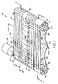
運搬物品を回転させるとともに本発明の特性を組み込んだコンベヤの一態様が図1乃至4に示されている。コンベヤ20は、第2の継目なしコンベヤベルト24に平行であって隣接している第1の継目なしコンベヤベルト22を具える。ベルトは互いに、物品が沿って運搬される上側運搬面26を規定する。ベルトの上側運搬面は、ウェアストリップ28、29又は支持ローラ30(図5)などの支持部材を具える運搬路に支持されている。コンベヤベルトは、駆動シャフト36に連結したモータ34を具える駆動装置によって運搬方向32に駆動される。駆動シャフトに取り付けられたスプロケット38は、運搬路の下流端部42においてベルトの内側40、41で駆動面と当接する。ベルトは、駆動スプロケット38と運搬路の上流端部43のアイドルスプロケット39との間に掛けられている。アイドルスプロケットはアイドルシャフト37に取り付けられている。シャフトは両方とも、コンベヤフレームに取り付けられた(図示せず)各端部の支持ブロック44において回転するように支持される。ベルトは支持されており、これらの弛みは、ローラ又はシュー48によって下側リターン路46に沿って小さくなる。
One embodiment of a conveyor that rotates the carrying article and incorporates the characteristics of the present invention is shown in FIGS.
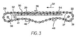
第1のコンベヤベルト22は、ベルトの厚みより大きい径を有する2セットのローラ50、51を具える。ローラの突出部がベルトの上側部52及び下側部53を越えて延在する。ローラ50、51の突出部は、支持部材、本実施例ではウェアストリップ29の平坦な上側部によって形成されるローラ当接支持面54に沿って動く。ローラは、ベルトが進むに伴い支持面に当接し、図3で矢印56によって示される方向に回転する。ベルトの一方の側部の縦領域47におけるローラ50は、横軸58(運搬方向に対して90°)で回転するように配列される。これらのローラ50は、主な運搬方向、すなわち、ベルトの移動方向32に平行に回転し、運搬物品を押すので、これらはインラインローラと呼ばれる。ベルト22の他方の側部により近い横にオフセットされた領域49におけるローラ51は、運搬方向及びインラインローラの軸に対して傾斜している軸59で回転するように配列されている。これらのローラ51は斜めローラと呼ばれる。ベルトが進むに伴い、各ローラは、その上で運搬される物品にローラの軸に対して垂直方向に力をかける。従って、インラインローラ50は物品を運搬方向32に押し、斜めローラ51は第2のベルト24に向けて斜めに物品を押す。
The
第2のベルト24は、運搬方向32に複数の平行する軸62で回転するように配列されたローラ60を具える。外側運搬面に第3の領域63を規定するこれらのローラ60は、その進行に対して横方向にベルトの側部へ向けて運搬物品を方向付けるので、これらは横ローラと呼ばれる。インラインローラ50及び斜めローラ51と異なり、横ローラ60は、運搬路に沿って支持面と接触しない。第2のベルトは、その代わりに、ローラのレーンの間の縦レーン64においてウェアストリップ28に直に支持される。横ローラは、側方へ動く物品と接触することによってこれらの軸を中心に回転自在である。横ローラは、支持面と当接する必要が無いので、これらは、ベルトの下側部53を越えて延在する必要がない。
The
第1のベルト22の支持面の別の態様が、ベルトの詳細とともに図5に示されている。図示されたベルト部分における斜めローラ51は、列に並んでモジュラーコンベヤベルトを形成するモジュール70に形成された空洞68の対向する壁にわたって延在している軸66に取り付けられている。各列の端部を案内してつなげるヒンジアイ72、73は、交互に配置されたヒンジアイによって形成される側方の通路に受けられるヒンジロッド74によって交互に配置され連結される。車軸は、ローラ51が中心として回転する斜軸59を規定する。ローラは、一般的に、ローラの本体部と同じプラスチック又は支持面の高摩擦グリップ用のゴムバンドによって形成される周辺トレッド76を具えており、円筒形である。ベルトモジュールは、射出成形法においてポリプロピレン、ポリエチレン、アセタール、又は合成高分子などの熱可塑性材料で作られることが好ましい。ヒンジロッドは、同様に、好適なプラスチック材料又はステンレス鋼で作ることができる。インラインローラは、横に方向付けられた車軸を具えるベルトモジュール内の同様の空洞に取り付けられる。第2のコンベヤベルトは、同様に、運搬方向に平行に配列された複数の車軸に空洞内で取り付けられた横ローラを具えて構成されている。
Another aspect of the support surface of the
斜めローラは、図4の平坦な上側ウェアストリップ29に乗る代わりに、円筒形状の外側面がローラ当接支持面80を形成する縦支持ローラ78に乗ることができる。各支持ローラは、斜めのベルトローラのレーンの下に配置される。支持ローラは、運搬方向32に平行な軸82を中心に回転自在である。コンベヤベルトが進むに伴い、ベルトローラは縦ローラとかみ合って回転接続する。斜めのベルトローラと縦ローラの間の回転接続は、斜めローラが支持面に沿ってスリップする傾向を減らす。平坦なウェアストリップは、斜めローラがインラインから約30°以下までずれても許容するが、縦ローラは、より良い支持面を提供し約45°以上の角度で斜めローラの摩耗を少なくする。縦ローラ78は、例えば、空気圧、液圧、又は電気的機構によって、斜めローラと接触したり、接触から外れるように矢印84によって示されるように上下してもよい。
Instead of riding on the flat
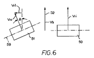
図6は、ベルトが運搬方向32に速度vb進むときのベルトに対するインラインローラ50及び斜めローラ51の速度のベクトル図である。支持面に沿ってスリップしない場合のベルトに対するインラインローラの接線速度Vriは、運搬方向におけるベルトの速度vbに等しい。(前進するベルトの速度にインラインローラの速度を重ねると、静止している観察者に対し、ベルトの速度の2倍の正味の接線ローラ速度をもたらす。)スリップしない状態のベルトに対する斜めローラの接線速度vroは、その軸59に対して垂直方向に向いており、vro=vbsecθで示すことができ、θは、インライン状態からのローラの角度である。斜めローラの速度の横成分vrlは、vbtanθに等しい。インラインローラと斜めローラとの間の唯一の違いが運搬方向に対するこれらの位置であって、両方とも平坦なウェアストリップに乗っている場合、斜めローラは、ベルトが進むに伴いインラインローラよりも多くスリップする。スリップの増加は、運搬方向における成分を含む斜めローラの速度を減少させる。インラインと斜めローラの両方の上に同時に配置される物品は、インラインと斜めローラの間の運搬方向におけるローラの速度差によって運搬面上で回転する。
Figure 6 is a vector diagram of the speed of the in-
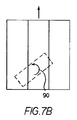
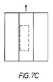
図1のコンベヤの動作が図7A乃至7Dに示されている。図7Aにおいて、物品86はコンベヤ20の上流に送り込まれる。本実施例では、物品の主軸88が最初に横に方向付けられている。第2の領域49における斜めローラのスリップが第1の領域47におけるインラインローラのスリップより大きい状態で、運搬方向32におけるインラインローラの速度成分Vriは、運搬方向における斜めローラの速度成分vroより大きい。進む速度のこの差によって、物品は、図7Bの矢印90によって示されるように左回りに回転する。そうしている間に、第2の領域49における斜めローラの横の速度成分が、図7Cに図示するように、コンベヤの左側部へ向けて物品を押す。得られる物品の回転角度又は得られる物品の範囲は、ベルトの速度、領域の幅、ベルトローラと支持面の間の当接の直線距離、及びベルトローラと当接面の間のスリップなどのパラメータを選択又は調節することによって設定することができる。選択されたパラメータの構造又はローラの回転速度の差が生じるようにそれを調整する手段は、運搬物品を回転する回転制御手段を構成する。本実施例において、回転制御手段によって、物品86は、回転自在な横ローラを具える第3の領域63上へ運搬面を横切って移動する時間内で約90°回転する。図7Dに示すように、物品は、第2の領域におけるローラによって押された物品の運動量によって、矢印92の方向に第3の領域を単に横切って移動する。
The operation of the conveyor of FIG. 1 is illustrated in FIGS. 7A-7D. In FIG. 7A, the
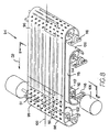
本発明に従って物品を回転し移動するコンベヤの別の態様が、図8及び9に示されている。コンベヤ94は、第1の縦レーン又は領域98におけるインラインローラ50と、横にオフセットされた第2のレーン又は領域99における斜めローラ51とを具えるコンベヤベルト96を具える。図示するように、図1のコンベヤのように、2つの領域が、コンベヤベルトの中心線100の対向する側部に並んでいる。コンベヤベルトの駆動装置102は、スプロケットと、駆動シャフトと、支持ブロックと、駆動モータとを具える。駆動装置は、ベルトを運搬方向32に進ませる。ウェアシート104に形成された静止した平坦な支持面が、第2の領域99における斜めローラ51の下にある。(ウェアシートの代わりにウェアストリップ又は縦の支持ローラを代替的に用いることができる。)インラインローラと十分に当接する高摩擦又は他の外側面を具える平坦なファブリックもしくはゴムのベルト又はモジュラープラスチックコンベヤベルトなどのベルト106が、第1の領域のインラインローラ50の下にあり接触する。図8及び9に示された平坦なベルトは、摩擦ローラ112のシャフト110に連結されたモータ108によって駆動される。ベルト106は、駆動ローラ112と伸張させるアイドルローラ114との間に掛けられている。両方のローラのシャフトの端部は、支持ブロック116に支持されている。運搬方向における平坦なベルト106の速度は、インラインローラの速度に作用する。例えば、平坦なベルトの速度がコンベヤベルト96の速度と同じである場合、平坦ベルトの外側面によって形成される支持面とインラインローラ50との間に相対運動はない。結果的に、インラインローラの接線速度は、その場合ゼロである。平坦ベルト106の速度がコンベヤベルト96の速度より小さい場合、ベルトの速度差によって、ローラは、ベルトの速度差に比例して運搬方向に回転する。平坦ベルトの速度がコンベヤベルトの速度より大きい場合、図10の速度ベクトル図によって示されるようにインラインローラは運搬方向と反対に回転する。従って、ローラに当接する平坦ベルトは、本実施例においてローラ制御手段を構成する。
Another embodiment of a conveyor for rotating and moving articles in accordance with the present invention is shown in FIGS.
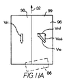
図8のコンベヤの動作が図11A乃至11Dに示されている。物品86はコンベヤベルト96の上流端に入り、運搬方向32に進む。ローラに当接する平坦ベルトがより大きい速度で動く状態で、第1の領域98におけるインラインローラは、矢印vriによって示されるように運搬方向と反対に回転する。第2の領域99における斜めローラは、静止したウェアストリップに沿って運搬方向の成分vrobを有する接線速度vroで回転する。2つの反対方向のローラ速度成分が、コンベヤベルトが進むに伴い図11Bの矢印120の方向に物品を回転させる。第2領域における斜めローラの速度vrotの横成分は、図11Cに示すように運搬面を側方へ横切るように物品を同時に押す。ベルトのパラメータは、運搬物品の図11Dのようにベルトの側部のその目的地への90°回転及び横移動による運搬物品の特性に合わせて調整することができる。
The operation of the conveyor of FIG. 8 is illustrated in FIGS. 11A-11D.
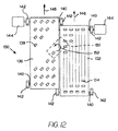
同じ結果を図12に示したコンベヤで達成することができる。コンベヤ130は、一対の並列のコンベヤベルトによって特徴づけられる。第1のベルト132はインラインローラ134を具え、第2のベルト136は斜めローラ138を具える。各ベルトにおけるローラは、これらの運搬路に沿ってベルトを支持する支持面と接触してベルトの厚さを通って突き出ている。運搬物品は、ベルトが進むに伴い支持面上で回転するローラ上に乗る。各ベルトは、独立した駆動部材とアイドル部材との間に掛けられており、スプロケット(図示せず)と、シャフト140と、支持ブロック142と、駆動モータ144とを具える。インラインローラのベルト132の速度146は斜めローラのベルト136の速度148より大きい場合、インラインローラの運搬方向における速度は斜めローラのそれより大きく、2つのベルトの間の隙間にわたる物品150に対するこれらの作用が矢印152によって示すように左回りに物品を回転させる。斜めローラは、同時に、コンベヤの斜めローラのベルトの側部へ向けて物品を押す。従って、運搬物品の配置は、個々の駆動装置を具える2つのベルトの相対速度を調整することによって制御することができ、共に、ローラ制御手段を構成する。
The same result can be achieved with the conveyor shown in FIG. The
図13に示したコンベヤにおいて、インラインローラのベルト156は、第1の速度158で運搬方向に運搬路に沿って進む。隣接する斜めローラのベルト160もまた、運搬方向に進むが、より遅い速度162である。斜めローラのベルトにおけるローラ164は、ベルトが進むに伴い、インラインローラのベルトに向けてローラの上で物品168を押すように配列された斜軸166を中心に回転する。両方のコンベヤベルトは、ローラがかみ合って回転接続する運搬路の下にある支持面に乗っている。インラインベルトのより早い速度によってそのローラ170は、運搬方向により早い速度で回転し、右回り方向172に運搬物品を回転させる。
In the conveyor shown in FIG. 13, the
本発明は、いくつかの好適な態様に関して詳細に記述されているが、他の態様が可能である。例えば、図12のコンベヤにおける支持面として速度を制御される平坦ベルトを使用して、ローラの相対回転速度の制御を補助することができる。同様に、態様のうちの一つに示された個々の特性を特定の運搬条件又は物品形状もしくは他の物理的特性を満たすように他の態様のうちの一つに有効に使用してもよい。従って、本発明の範囲は、詳細に記述された特定の態様に制限されることを意味するものではない。 Although the present invention has been described in detail with respect to certain preferred embodiments, other embodiments are possible. For example, a speed controlled flat belt can be used as the support surface in the conveyor of FIG. 12 to assist in controlling the relative rotational speed of the rollers. Similarly, the individual properties shown in one of the embodiments may be effectively used in one of the other embodiments to meet a specific transport condition or article shape or other physical property. . Accordingly, the scope of the invention is not meant to be limited to the particular embodiments described in detail.
Claims (9)
上流端部から下流端部へ運搬方向に縦に、及び第1の側縁部から第2の側縁部までの幅で横に延在する運搬路と;
前記運搬路に沿って所定のベルト速度で前記運搬方向に進むとともに、外側の運搬面を形成する少なくとも1のコンベヤベルトであって、当該コンベヤベルトは、前記コンベヤベルトの厚さを通って上方へ延在し、前記運搬路に沿って運搬物品と支持接触するローラを具え、
前記外側の運搬面は、前記第1の側縁部に近い第1の領域と、前記第2の側縁部に近い横にオフセットされた第2の領域とを具える少なくとも2つの領域に分けられ、前記第1の領域におけるローラは、第1の方向に回転するように方向付けられ、前記第2の領域におけるローラは、前記第1の方向とは異なる第2の方向に回転するように方向付けられているコンベヤベルトと;
前記第1の領域における前記ローラを第1の速度で、前記第2の領域における前記ローラを第2の速度で回転させるローラ制御手段とを具え;
前記第1の速度の前記運搬方向の成分は、前記第2の速度の前記運搬方向の成分と大きさが異なり、
前記第1の領域が前記第1の側縁部へ横に延在し、前記第2の領域が前記第2の側縁部へ横に延在することを特徴とするコンベヤ。 In the conveyor,
A transport path extending longitudinally in the transport direction from the upstream end to the downstream end and laterally with a width from the first side edge to the second side edge;
At least one conveyor belt traveling in the conveying direction at a predetermined belt speed along the conveying path and forming an outer conveying surface, wherein the conveyor belt moves upward through the thickness of the conveyor belt A roller that extends and is in support contact with the transport article along the transport path;
The outer conveying surface is divided into at least two regions comprising a first region near the first side edge and a laterally offset second region near the second side edge. The rollers in the first region are oriented to rotate in a first direction, and the rollers in the second region are rotated in a second direction different from the first direction. A conveyor belt being oriented;
Roller control means for rotating the roller in the first region at a first speed and rotating the roller in the second region at a second speed;
The conveying direction component of the first speed is different in magnitude from the conveying direction component of the second speed,
A conveyor wherein the first region extends laterally to the first side edge and the second region extends laterally to the second side edge.
少なくとも1のコンベヤベルトを所定のベルト速度で運搬方向に進ませるステップであって、前記コンベヤベルトが、前記コンベヤベルトの厚さを通って延在して第1の方向に回転するように配列された第1の領域における第1のローラと、前記コンベヤベルトの厚さを通って延在して前記第1の方向とは異なる第2の方向に回転するように配列された第2の領域における第2のローラとを具える横にオフセットされた第1及び第2の領域に分けられた上側運搬面を具えるステップと;
第1の速度で前記第1の方向に前記第1のローラを、及び第2の速度で前記第2の方向に前記第2のローラを回転させるステップであって、同時に第1及び第2のローラ上の前記第1及び第2の領域における物品を前記上側運搬面で回転させるステップとを具え;
前記第1の速度の前記運搬方向の成分は、前記第2の速度の前記運搬方向の成分と大きさが異なり、
前記第1の領域を前記上側運搬面の一方の側縁部へ横に延在させ、前記第2の領域を前記上側運搬面の他方の側縁部へ横に延在させることを特徴とする方法。 In a method of changing the direction of an article conveyed on a belt conveyor:
Advancing at least one conveyor belt in a conveying direction at a predetermined belt speed, wherein the conveyor belt extends through the thickness of the conveyor belt and is arranged to rotate in a first direction. a first roller in the first region, the second region which is arranged to rotate in a second direction different from the extending through the thickness first direction of said conveyor belt Providing an upper conveying surface divided into laterally offset first and second regions comprising a second roller;
Rotating the first roller in the first direction at a first speed and the second roller in the second direction at a second speed, wherein the first and second Rotating the articles in the first and second areas on a roller on the upper conveying surface;
The conveying direction component of the first speed is different in magnitude from the conveying direction component of the second speed,
The first region extends laterally to one side edge of the upper transport surface, and the second region extends laterally to the other side edge of the upper transport surface. Method.
Applications Claiming Priority (3)
| Application Number | Priority Date | Filing Date | Title |
|---|---|---|---|
| US80484406P | 2006-06-15 | 2006-06-15 | |
| US60/804,844 | 2006-06-15 | ||
| PCT/US2007/070307 WO2007146633A2 (en) | 2006-06-15 | 2007-06-04 | Article-rotating belt conveyor |
Publications (3)
| Publication Number | Publication Date |
|---|---|
| JP2009539736A JP2009539736A (en) | 2009-11-19 |
| JP2009539736A5 JP2009539736A5 (en) | 2010-09-09 |
| JP5280353B2 true JP5280353B2 (en) | 2013-09-04 |
Family
ID=38832643
Family Applications (1)
| Application Number | Title | Priority Date | Filing Date |
|---|---|---|---|
| JP2009515564A Active JP5280353B2 (en) | 2006-06-15 | 2007-06-04 | Belt conveyor for rotating articles |
Country Status (8)
| Country | Link |
|---|---|
| US (1) | US7731010B2 (en) |
| EP (1) | EP2027045A2 (en) |
| JP (1) | JP5280353B2 (en) |
| KR (1) | KR20090029783A (en) |
| CN (1) | CN101466621B (en) |
| AU (1) | AU2007257968A1 (en) |
| BR (1) | BRPI0711680A2 (en) |
| WO (1) | WO2007146633A2 (en) |
Families Citing this family (38)
| Publication number | Priority date | Publication date | Assignee | Title |
|---|---|---|---|---|
| JP4425000B2 (en) * | 2004-01-06 | 2010-03-03 | 株式会社ブリヂストン | Rubber member conveying device and rubber member supply system having the same |
| US7971701B2 (en) * | 2006-01-26 | 2011-07-05 | Laitram, L.L.C. | Diagonal sorter |
| US8123021B2 (en) * | 2007-08-27 | 2012-02-28 | Laitram, L.L.C. | Methods for singulating abutting articles |
| WO2009061981A1 (en) * | 2007-11-09 | 2009-05-14 | Laitram, L.L.C. | Bottom case turner |
| DE102008050524A1 (en) * | 2008-10-06 | 2010-04-08 | Wincor Nixdorf International Gmbh | Device for aligning notes of value |
| US7743905B2 (en) * | 2008-10-30 | 2010-06-29 | Laitram, L.L.C. | Transverse-roller-belt conveyor and methods for case turning |
| US8167118B2 (en) * | 2009-09-10 | 2012-05-01 | Laitram, L.L.C. | Conveyors, belts, and modules with actuated rollers |
| US8322518B2 (en) | 2010-04-15 | 2012-12-04 | Laitram, L.L.C. | Carousel conveyor and method |
| KR200470381Y1 (en) | 2010-08-19 | 2013-12-11 | 주식회사 동일테크 | Timing belt for conveying glass for flat panel |
| US8205738B1 (en) | 2011-04-08 | 2012-06-26 | Laitram, L.L.C. | Two-belt passive-roller case turner |
| JP2014024640A (en) * | 2012-07-26 | 2014-02-06 | Tsubakimoto Chain Co | Direction changing mechanism, conveyance direction changing device and sorting device |
| US8915353B2 (en) | 2012-09-12 | 2014-12-23 | Laitram, L.L.C. | Belt conveyor system, roller-engagement mechanism, and related method |
| CN104884370B (en) * | 2012-10-25 | 2017-07-04 | 英特里格拉特德总部有限公司 | Driver with variable outbound course |
| WO2015108481A1 (en) * | 2014-01-20 | 2015-07-23 | C. Gunnarssons Verkstads Ab | Method and apparatus for single feeding of elongate objects |
| CA2873752C (en) | 2014-01-24 | 2021-03-09 | Axium Inc. | Product orientor |
| EP3164241A4 (en) * | 2014-07-02 | 2018-04-11 | Doben Limited | System and method with floating welder for high rate production welding |
| CN107108124B (en) | 2014-10-31 | 2020-08-11 | 莱克斯诺工业有限公司 | Actively controlling operation of a roller top transport assembly |
| IL238444B (en) * | 2015-04-22 | 2018-08-30 | Israel Aerospace Ind Ltd | Baggage handling system |
| CN104872776A (en) * | 2015-04-30 | 2015-09-02 | 浙江海洋学院 | Freezing equipment for keeping fresh meat quality of swimming crab |
| CN105105286B (en) * | 2015-07-03 | 2018-06-15 | 浙江省海洋水产研究所 | The quick freezing unit of squid |
| US10343851B2 (en) | 2015-08-05 | 2019-07-09 | Laitram, L.L.C. | Article diverting conveyor belt |
| CN105501808B (en) * | 2015-12-24 | 2018-03-23 | 重庆代发铸造有限公司 | Conveyer for triangle connection element |
| EP3246274A1 (en) * | 2016-05-20 | 2017-11-22 | Siemens Aktiengesellschaft | Conveyor section for conveying sorted items in different directions |
| FI127431B (en) * | 2016-08-08 | 2018-05-31 | Oy Checkmark Ltd | A checkout desk with a rear desk structure |
| WO2018165489A1 (en) | 2017-03-08 | 2018-09-13 | Advanced Technology & Research Corp. | Package sorting transfer module and systems and methods therefor |
| US10532894B2 (en) | 2017-03-10 | 2020-01-14 | Regal Beloit America, Inc. | Modular transfer units, systems, and methods |
| DE102017120730A1 (en) * | 2017-09-08 | 2019-03-14 | Khs Gmbh | Device and method for aligning containers |
| EP3473575B1 (en) * | 2017-10-19 | 2020-08-19 | Otis Elevator Company | Drive belt for people conveyors |
| CN108058859A (en) * | 2017-11-20 | 2018-05-22 | 佛山科学技术学院 | A kind of egg loading mechanism |
| US10640303B2 (en) * | 2017-11-22 | 2020-05-05 | Regal Beloit America, Inc. | Modular sortation units, systems, and methods |
| US10822177B2 (en) | 2018-05-09 | 2020-11-03 | Intelligrated Headquarters, Llc | Method and system for manipulating articles |
| US11458635B2 (en) | 2018-05-09 | 2022-10-04 | Intelligrated Headquarters, Llc | Method and system for manipulating articles |
| US11318620B2 (en) * | 2018-05-09 | 2022-05-03 | Intelligrated Headquarters, Llc | Method and system for manipulating items |
| CN111776682B (en) * | 2020-07-28 | 2021-11-19 | 东方互联(山东)信息科技有限公司 | A adjustment platform equipment for industry pile up neatly |
| CN112495851B (en) * | 2020-10-28 | 2023-10-20 | 蒙城县佰世达木业有限公司 | Fiberboard processing equipment |
| EP4056503A1 (en) * | 2021-03-10 | 2022-09-14 | Fameccanica.Data S.p.A. | Apparatus and method for varying the pitch between moving articles |
| CN114162547A (en) * | 2021-12-28 | 2022-03-11 | 昆明昆船逻根机场系统有限公司 | Article conveying device and method |
| CN115593852B (en) * | 2022-11-08 | 2023-03-28 | 常州科顺检测技术服务有限公司 | Conveying mechanism for new forms of energy electric power energy storage lithium cell aging testing platform |
Family Cites Families (26)
| Publication number | Priority date | Publication date | Assignee | Title |
|---|---|---|---|---|
| US4143756A (en) | 1975-05-16 | 1979-03-13 | Conveyor Manufacturing Company Limited | Conveyor orientation unit |
| US3973672A (en) | 1975-05-28 | 1976-08-10 | Alvey Inc. | Article conveying and orienting apparatus |
| US4541768A (en) * | 1983-10-13 | 1985-09-17 | Fmc Corporation | Container trailer |
| JPS6242152A (en) * | 1985-08-15 | 1987-02-24 | Fuji Photo Film Co Ltd | Image forming method |
| US4676361A (en) | 1985-09-03 | 1987-06-30 | Heisler Raymond A | Troughing conveyors for carton or bag orienting and conveying |
| DE3718206A1 (en) | 1987-05-29 | 1988-12-15 | Will E C H Gmbh & Co | DEVICE FOR CONVEYING AND ROTATING PAPER STACKS |
| US5092447A (en) | 1990-02-26 | 1992-03-03 | Wyard Industries, Inc. | Pattern-forming conveyor apparatus for container palletizing |
| US5145049A (en) | 1990-10-12 | 1992-09-08 | Mcclurkin Jack | Pattern forming conveyor |
| DE4041477A1 (en) * | 1990-12-22 | 1992-06-25 | Natec Reich Summer Gmbh Co Kg | TURNING DEVICE FOR PRODUCTS CONVEYED ON A CONVEYOR BELT |
| FR2684975B1 (en) * | 1991-12-13 | 1994-03-11 | Lucas Sa | DEVICE FOR HANDLING AND ORIENTATION OF FLAT OBJECTS ARRANGED IN PACKETS. |
| US5400896A (en) | 1993-10-13 | 1995-03-28 | Western Atlas Inc. | Unscrambling conveyor |
| US6494312B2 (en) | 1998-11-02 | 2002-12-17 | The Laitram Corporation | Modular roller-top conveyor belt with obliquely-arranged rollers |
| EP1189707A4 (en) | 1999-04-30 | 2008-03-05 | Siemens Ag | Item singulation system |
| CN2434279Y (en) * | 2000-06-29 | 2001-06-13 | 袁仲雪 | Conveyer belt feeder |
| US6758323B2 (en) * | 2002-05-30 | 2004-07-06 | The Laitram Corporation | Singulating conveyor |
| US6571937B1 (en) * | 2002-09-13 | 2003-06-03 | The Laitram Corporation | Switch conveyor |
| CN2630198Y (en) * | 2003-03-18 | 2004-08-04 | 煤炭科学研究总院上海分院 | Belt conveyer |
| US6923309B2 (en) | 2003-10-03 | 2005-08-02 | Laitram, L.L.C. | Article-orienting conveyor |
| US6968941B2 (en) | 2003-11-21 | 2005-11-29 | Materials Handling Systems, Inc. | Apparatus and methods for conveying objects |
| US7111722B2 (en) | 2004-08-13 | 2006-09-26 | Laitram, L.L.C. | Angled-roller belt conveyor |
| BRPI0516182A (en) * | 2004-09-28 | 2008-08-26 | Laitram Llc | apparatus and methods for switching high-speed conveyors |
| US7097029B2 (en) | 2004-12-23 | 2006-08-29 | Krones Ag. | Parcel goods aligning device |
| US7007792B1 (en) | 2005-03-08 | 2006-03-07 | Laitram, L.L.C. | Angled-roller article-rotating belt conveyor |
| US7389867B2 (en) | 2005-05-27 | 2008-06-24 | Scandia Technologies | Systems and methods for orienting and conveying articles |
| WO2007084606A2 (en) | 2006-01-20 | 2007-07-26 | L-3 Communications Security And Detection Systems, Inc. | Article positioner for a conveyor system |
| GB2434569B (en) | 2006-01-25 | 2008-01-23 | Herbert R J Eng Ltd | Conveyor |
-
2007
- 2007-06-04 BR BRPI0711680-2A patent/BRPI0711680A2/en not_active IP Right Cessation
- 2007-06-04 US US12/301,271 patent/US7731010B2/en active Active
- 2007-06-04 EP EP07812006A patent/EP2027045A2/en not_active Withdrawn
- 2007-06-04 CN CN2007800220955A patent/CN101466621B/en active Active
- 2007-06-04 KR KR1020097000244A patent/KR20090029783A/en not_active Application Discontinuation
- 2007-06-04 WO PCT/US2007/070307 patent/WO2007146633A2/en active Application Filing
- 2007-06-04 AU AU2007257968A patent/AU2007257968A1/en not_active Abandoned
- 2007-06-04 JP JP2009515564A patent/JP5280353B2/en active Active
Also Published As
| Publication number | Publication date |
|---|---|
| CN101466621A (en) | 2009-06-24 |
| AU2007257968A1 (en) | 2007-12-21 |
| JP2009539736A (en) | 2009-11-19 |
| US7731010B2 (en) | 2010-06-08 |
| BRPI0711680A2 (en) | 2011-12-20 |
| CN101466621B (en) | 2012-05-23 |
| EP2027045A2 (en) | 2009-02-25 |
| US20090200139A1 (en) | 2009-08-13 |
| KR20090029783A (en) | 2009-03-23 |
| WO2007146633A2 (en) | 2007-12-21 |
| WO2007146633A3 (en) | 2008-07-31 |
Similar Documents
| Publication | Publication Date | Title |
|---|---|---|
| JP5280353B2 (en) | Belt conveyor for rotating articles | |
| CN103443000B (en) | Case turner and for making the method for article rotating transmitted | |
| JP5563457B2 (en) | Method for unifying adjacent articles | |
| KR101335779B1 (en) | Sorter belt conveyor | |
| US7607533B2 (en) | Conveyors and methods for non-uniformly accelerating conveyed articles | |
| AU2003204355B2 (en) | Singulating conveyor | |
| US7942257B2 (en) | Roller-belt conveyor with infeed pull-away | |
| JP2009539736A5 (en) | ||
| KR20130055593A (en) | Carousel conveyor and method |
Legal Events
| Date | Code | Title | Description |
|---|---|---|---|
| RD04 | Notification of resignation of power of attorney |
Free format text: JAPANESE INTERMEDIATE CODE: A7424 Effective date: 20100227 |
|
| A521 | Request for written amendment filed |
Free format text: JAPANESE INTERMEDIATE CODE: A523 Effective date: 20100603 |
|
| A621 | Written request for application examination |
Free format text: JAPANESE INTERMEDIATE CODE: A621 Effective date: 20100603 |
|
| A521 | Request for written amendment filed |
Free format text: JAPANESE INTERMEDIATE CODE: A523 Effective date: 20100901 |
|
| A131 | Notification of reasons for refusal |
Free format text: JAPANESE INTERMEDIATE CODE: A131 Effective date: 20120626 |
|
| A977 | Report on retrieval |
Free format text: JAPANESE INTERMEDIATE CODE: A971007 Effective date: 20120629 |
|
| A521 | Request for written amendment filed |
Free format text: JAPANESE INTERMEDIATE CODE: A523 Effective date: 20120924 |
|
| A131 | Notification of reasons for refusal |
Free format text: JAPANESE INTERMEDIATE CODE: A131 Effective date: 20130108 |
|
| A521 | Request for written amendment filed |
Free format text: JAPANESE INTERMEDIATE CODE: A523 Effective date: 20130219 |
|
| A131 | Notification of reasons for refusal |
Free format text: JAPANESE INTERMEDIATE CODE: A131 Effective date: 20130312 |
|
| A521 | Request for written amendment filed |
Free format text: JAPANESE INTERMEDIATE CODE: A523 Effective date: 20130329 |
|
| TRDD | Decision of grant or rejection written | ||
| A01 | Written decision to grant a patent or to grant a registration (utility model) |
Free format text: JAPANESE INTERMEDIATE CODE: A01 Effective date: 20130423 |
|
| A61 | First payment of annual fees (during grant procedure) |
Free format text: JAPANESE INTERMEDIATE CODE: A61 Effective date: 20130522 |
|
| R150 | Certificate of patent or registration of utility model |
Free format text: JAPANESE INTERMEDIATE CODE: R150 Ref document number: 5280353 Country of ref document: JP Free format text: JAPANESE INTERMEDIATE CODE: R150 |
|
| R250 | Receipt of annual fees |
Free format text: JAPANESE INTERMEDIATE CODE: R250 |
|
| R250 | Receipt of annual fees |
Free format text: JAPANESE INTERMEDIATE CODE: R250 |
|
| R250 | Receipt of annual fees |
Free format text: JAPANESE INTERMEDIATE CODE: R250 |
|
| R250 | Receipt of annual fees |
Free format text: JAPANESE INTERMEDIATE CODE: R250 |
|
| R250 | Receipt of annual fees |
Free format text: JAPANESE INTERMEDIATE CODE: R250 |
|
| R250 | Receipt of annual fees |
Free format text: JAPANESE INTERMEDIATE CODE: R250 |
|
| R250 | Receipt of annual fees |
Free format text: JAPANESE INTERMEDIATE CODE: R250 |
|
| R250 | Receipt of annual fees |
Free format text: JAPANESE INTERMEDIATE CODE: R250 |